WO2019047633A1 - Dispositif intégré d'encapsulation de transducteur de réception d'ondes acoustiques de diagraphie en cours de forage - Google Patents
Dispositif intégré d'encapsulation de transducteur de réception d'ondes acoustiques de diagraphie en cours de forage Download PDFInfo
- Publication number
- WO2019047633A1 WO2019047633A1 PCT/CN2018/097793 CN2018097793W WO2019047633A1 WO 2019047633 A1 WO2019047633 A1 WO 2019047633A1 CN 2018097793 W CN2018097793 W CN 2018097793W WO 2019047633 A1 WO2019047633 A1 WO 2019047633A1
- Authority
- WO
- WIPO (PCT)
- Prior art keywords
- bellows
- plug
- receiving transducer
- processing circuit
- signal processing
- Prior art date
- Legal status (The legal status is an assumption and is not a legal conclusion. Google has not performed a legal analysis and makes no representation as to the accuracy of the status listed.)
- Ceased
Links
Images

Classifications
-
- G—PHYSICS
- G01—MEASURING; TESTING
- G01V—GEOPHYSICS; GRAVITATIONAL MEASUREMENTS; DETECTING MASSES OR OBJECTS; TAGS
- G01V1/00—Seismology; Seismic or acoustic prospecting or detecting
- G01V1/16—Receiving elements for seismic signals; Arrangements or adaptations of receiving elements
- G01V1/162—Details
-
- E—FIXED CONSTRUCTIONS
- E21—EARTH OR ROCK DRILLING; MINING
- E21B—EARTH OR ROCK DRILLING; OBTAINING OIL, GAS, WATER, SOLUBLE OR MELTABLE MATERIALS OR A SLURRY OF MINERALS FROM WELLS
- E21B47/00—Survey of boreholes or wells
- E21B47/01—Devices for supporting measuring instruments on drill bits, pipes, rods or wirelines; Protecting measuring instruments in boreholes against heat, shock, pressure or the like
- E21B47/017—Protecting measuring instruments
-
- G—PHYSICS
- G01—MEASURING; TESTING
- G01V—GEOPHYSICS; GRAVITATIONAL MEASUREMENTS; DETECTING MASSES OR OBJECTS; TAGS
- G01V1/00—Seismology; Seismic or acoustic prospecting or detecting
- G01V1/40—Seismology; Seismic or acoustic prospecting or detecting specially adapted for well-logging
- G01V1/44—Seismology; Seismic or acoustic prospecting or detecting specially adapted for well-logging using generators and receivers in the same well
- G01V1/46—Data acquisition
-
- G—PHYSICS
- G01—MEASURING; TESTING
- G01V—GEOPHYSICS; GRAVITATIONAL MEASUREMENTS; DETECTING MASSES OR OBJECTS; TAGS
- G01V1/00—Seismology; Seismic or acoustic prospecting or detecting
- G01V1/40—Seismology; Seismic or acoustic prospecting or detecting specially adapted for well-logging
- G01V1/52—Structural details
- G01V1/523—Damping devices
-
- G—PHYSICS
- G01—MEASURING; TESTING
- G01V—GEOPHYSICS; GRAVITATIONAL MEASUREMENTS; DETECTING MASSES OR OBJECTS; TAGS
- G01V1/00—Seismology; Seismic or acoustic prospecting or detecting
- G01V1/40—Seismology; Seismic or acoustic prospecting or detecting specially adapted for well-logging
- G01V1/52—Structural details
- G01V2001/526—Mounting of transducers
Definitions
- the invention relates to the field of sonic logging while drilling, and particularly relates to an integrated while drilling acoustic wave receiving transducer packaging device.
- Drilling while drilling logging technology is one of the methods of logging while drilling technology.
- the Drilling Acoustic Wave Transducer is the most important original of the LWD instrument. When the LWD instrument is working, it is generated by the transmitting transducer built into the LWD instrument. The acoustic wave is then received by the receiving transducer in the same instrument, and the specific properties of the medium are evaluated by acoustic information such as the wave velocity and attenuation of the various mode waves received.
- the acoustic transducer Due to the muddy water eye in the middle of the drilling instrument, the acoustic transducer is mounted on the outer wall of the drill collar and is difficult to be sealed in the oil as in the cable sonic tool. Therefore, conventional LWD transducers are usually packaged separately. .
- the two well-developed sonic wave receiving transducers are the button receiving transducer and the receiving transducer received by the ring package, and the button receiving transducer is directly mounted on the receiving end of the sonic instrument. At the same time, the transducer has a high downhole receiving sensitivity.
- the annular package receiving transducer encapsulates a plurality of receiving transducers in a ring-shaped strip structure, and the receiving chip is internally connected in parallel to form a receiving transducer, and the receiving transducer is mainly used for a monopole while drilling acoustic wave instrument.
- the transducer of the structure has a ceramic structure crystal packaged in a button-type metal structure, and the balance between the external mud of the ceramic piece crystal and the internal hydraulic oil is realized by the hydraulic balance device in the button metal structure, and the ceramic piece crystal is in the button In the structure, dynamic sealing is required, that is, the pressure of the external mud of the ceramic piece crystal and the internal hydraulic oil is balanced.
- the button-type receiving transducer is directly mounted on the receiving electronic warehouse skeleton, and the outer mud and the electronic warehouse are sealed by the sealing ring on the outer side of the button structure, and the double-core electrical connecting pin at the bottom of the transducer can realize and receive the circuit
- the short-distance connection allows the reception of weak acoustic signals.
- the annular potting receives the transducer package.
- the transducer of the structure adopts a chip ceramic crystal piece structure, and the receiving chip is packaged in an endless belt, and the receiving chip is internally connected in parallel to form a receiving transducer.
- the annular strip structure leads the chip receiving signal line through the sealing structure, and electrically connects the two signal receiving lines to the internal electronic warehouse through a specially designed sealed electrical connecting plug.
- the transducer with epoxy potting can be immersed in the mud, and the external mud and the internal electronic warehouse are sealed by a specially designed sealed electrical connection plug, thereby achieving the reception of weak acoustic signals.
- the button-type receiving transducer packaging device increases the complexity of the transducer design due to the requirement of the hydraulic dynamic balance design of the ceramic crystal piece, and the structure is easy to be ineffective in use; the button-type transducer ceramic crystal piece passes through the outside The surface is bonded with a layer of PEEK material exposed to the mud, which is prone to damage in the complex application environment; the structure increases the internal electrons because the transducer is mounted on the internal electronic warehouse frame while achieving high-pressure sealing with the drill collar. Processing and assembly requirements for the silo frame and external drill collar.
- the annular potting receiving transducer packaging device requires a specially designed sealing electrical connection insert to realize the electrical connection with the internal electronic warehouse, so as to meet the plug-in and realize the high sealing, and realize the docking with the electrical connector of the electronic warehouse, and at the same time, due to the underground
- the use environment of strong vibration shock requires that the insert be fixed to the drill collar.
- this kind of package structure requires a specially designed sealing insert, on the other hand, it also increases the processing and assembly requirements of the internal electronic warehouse frame and the external drill collar.
- the structure is increased. The length of the electrical connection line from the transducer to the electronic compartment affects the extraction of the signal.
- the object of the present invention is to overcome the deficiencies of the prior art, and to provide an integrated LWD acoustic transducer packaging device, which can be applied to a sonic and multi-pole sonic wave acoustic wave receiving system.
- the integrated sonic wave receiving transducer packaging device of the invention comprises a main body, a damping rubber and a connecting unit;
- the main body includes a plurality of receiving transducers, a signal processing circuit, an inner support frame, and a rectangular bellows; a plurality of the receiving transducers are directly disposed on the signal processing circuit, and the signal processing circuit is mounted on the An inner support frame, the inner support frame is sleeved into the rectangular bellows; the rectangular bellows is a sealed structure as a whole, and the inside is filled with an oil body; the rectangular bellows has a deformable surface of a corrugated structure on one side, and the other three sides are flat The receiving transducer is disposed on one side of the deformable surface;
- the damping rubber is U-shaped and wrapped around the outer circumference of the body
- the connecting unit is connected to the signal processing circuit at one end and to the internal main control circuit of the LWD device at the other end.
- a bellows joint is disposed at one end of the rectangular bellows, and a bellows plug is disposed at the other end, and the bellows joint and the bellows plug are integrally welded with the rectangular bellows;
- the bellows joint and the bellows plug are connected by a screw;
- the bellows plug is provided with an oil inlet and an oil outlet;
- the rectangular bellows, the bellows joint and the bellows plug together form a closed space .
- the connecting unit comprises a first multi-core sealing pin, a second multi-core sealing pin, a connecting plug, a first sealing ring, a second sealing ring, a third sealing ring, a retaining ring, and a multi-core sealing rubber sleeve ;
- the first multi-core sealing pin is mounted on one end of the bellows connector and the inner support frame, and one end of the first multi-core sealing pin is connected to a signal receiving line of the signal processing circuit, and the other end Connecting with a signal line of the second multi-core sealing pin;
- the first multi-core sealing pin is sealed to the bellows joint by the first sealing ring, and an outward end of the bellows connector is connected to the connecting plug by a screw; and the connecting plug passes through the connecting plug a circular boss is inserted into the bellows joint, the second sealing ring is disposed on the circular boss, and the second sealing ring forms a sealed space between the connecting plug and the inside of the bellows joint; a signal line of the first multi-core sealing pin is connected to the second multi-core sealed pin signal line mounted on the other end of the connecting plug through a through hole in the circular boss of the connecting plug;
- the second multi-core sealing pin forms a seal with the connecting plug through a third sealing ring, and the second multi-core sealing pin is fixed to the connecting plug through a retaining ring;
- the second multi-core sealing pin is inserted into the plug, and the other end is connected to the internal main control circuit of the LWD device through a signal line.
- the receiving transducer is a circular sheet-like structure, and is soldered to the signal processing circuit by soldering.
- the number of the receiving transducers is six, and is evenly arranged at intervals of 152.4 mm to 203 mm.
- the rectangular bellows is made of 0.2 mm stainless steel material.
- damping rubber and the rectangular bellows are bonded by a high temperature adhesive.
- each of the two sides of the bottom of the damping rubber is provided with a plurality of trapezoidal protrusions, which can slide the device along the groove of the casing of the drilling instrument into the installation position;
- the drill instrument housing is fixed by a cover plate and a screw.
- the oil body is a silicone oil and the pressure is 0.1-0.2 MPa.
- the cover plate has a thickness of not more than 3 mm under the condition of satisfying the structural strength.
- shock absorbing rubber has a hardness of 70, which can achieve decoupling of the receiving transducer from the drill collar, thereby eliminating interference of the drill collar wave with the receiving transducer.
- the utility model has the advantages that the integrated package structure is adopted, and the structure is convenient to install; the transducer is directly mounted on the circuit board, and can be processed in real time when the transducer receives the signal, thereby reducing signal interference, and is particularly suitable for underground engineering.
- High noise working environment adopts bellows encapsulation structure and hydraulic balance with external mud; the fixed cover plate of the packaging device adopts light and thin structure, which improves the penetration of sound waves, thereby improving the receiving of the receiving transducer inside the packaging device.
- Sensitivity the package device provides a feasible design solution for the sonic wave receiving transducer package, and the structure design is reasonable, novel and has broad application prospects.
- FIG. 1 is a cross-sectional view showing a package device for an integrated Drilling Acoustic Wave Receiver Transducer according to an embodiment of the present invention.
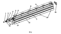
- FIG. 2 is a schematic diagram showing the structure (separation) of an integrated LWD receiving transducer package device according to an embodiment of the present invention.
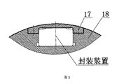
- Figure 3 is a schematic diagram showing the connection relationship between the package device and the instrument while drilling.
- an integrated lWD acoustic transducer receiving device package includes a main body, a damping rubber 12, and a connecting unit.
- the main body includes a plurality of receiving transducers 8, a signal processing circuit (circuit board) 9, an inner support frame 6, and a rectangular bellows 7; a plurality of the receiving transducers 8 are directly disposed on the signal processing circuit 9.
- the receiving transducer 8 is a circular sheet-like structure, and is soldered to the signal processing circuit 9 by soldering. In this embodiment, the number of the receiving transducers 8 is six, and is evenly arranged at intervals of 152.4 mm to 203 mm.
- the signal processing circuit 9 is mounted on the inner support frame 6, and the two can be connected by screws or other means; the inner support frame 6 is nested into the rectangular bellows 7; the rectangular bellows 7 as a whole
- the sealing structure is internally filled with an oil body 11; the rectangular bellows 7 has a deformable surface of a corrugated structure on one side, and the other three sides are flat; the receiving transducer 8 is disposed on one side of the deformable surface;
- the damping rubber 12 has a U-shaped structure and is wrapped around the outer circumference of the main body.
- the deformable surface of the corrugated structure is an open surface and is not in contact with the damping rubber 12; preferably, the damping rubber 12 and the rectangular corrugation
- the 7 tubes are bonded by a high temperature adhesive.
- the connecting unit has one end connected to the signal processing circuit 9 and the other end connected to the internal control circuit of the LWD instrument.
- the rectangular bellows 7 is made of 0.2 mm stainless steel material; the rectangular bellows 7 is provided with a bellows joint 4 at one end and a bellows plug 10 at the other end, the bellows joint 4 and the bellows plug 10 is welded integrally with the rectangular bellows 7; the two ends of the inner support frame 6 are respectively connected with the bellows joint 4 and the bellows plug 10 by screws; the bellows plug 10 is provided with oil.
- the rectangular bellows 7, the bellows joint 4, and the bellows plug 10 together form a closed space; the oil body 11 is injected into the bellows through the oil inlet and the oil outlet, the oil body 11
- a variety of options are possible, preferably silicone oil, at a pressure of from 0.1 to 0.2 MPa.
- the connecting unit is configured to connect the main body and the instrument while drilling to ensure isolation from the external mud, and can be implemented in various manners.
- the connecting unit comprises a first multi-core sealing pin 5 and a second multi-core sealing.
- Pin 2 connecting plug 3, first sealing ring 13, second sealing ring 14, third sealing ring 15, retaining ring 16, multi-core sealing rubber sleeve 1;
- the first multi-core sealing pin 5 is mounted on one end of the bellows joint 4 connected to the inner support frame 6, and the signal receiving of the first multi-core sealing pin 5 and the signal processing circuit 9 is received. a wire connection, the other end of which is connected to a signal line of the second multi-core sealing pin 2;
- the first multi-core sealing pin 5 is sealed to the bellows connector 4 by the first sealing ring 13, and the outward end of the bellows connector 4 is screwed to the connecting plug 3;
- the connecting plug 3 is inserted into the bellows joint 4 through a circular boss on which the second sealing ring 14 is disposed, the second sealing ring 14 is such that the connecting plug 3 is The inside of the bellows joint 4 forms a sealed space;
- the signal line of the first multi-core sealing pin 5 passes through the through hole in the circular boss of the connecting plug 3 and the other end of the connecting plug 3
- the second multi-core sealing pin 2 is sealed with the connecting plug 3 through a third sealing ring 15, and the second multi-core sealing pin 2 is fixed to the connecting plug 3 through a retaining ring 16;
- One end of the core sealing rubber sleeve 1 is inserted into the second multi-core sealing pin 2, and the other end is connected to the internal main control circuit of the LWD device through a signal line.
- the two sides of the bottom of the damping rubber 12 are provided with a plurality of trapezoidal protrusions 19, which can slide the device along the groove of the drilling tool housing 18 into the installation position;
- the LWD device 18 is fixed by a cover plate 17 and a screw, as shown in FIG. 3;
- the cover plate 17 has a thickness of not more than 3 mm under the condition of satisfying the structural strength.
- the damping rubber 12 has a hardness of 70, which can achieve the decoupling of the receiving transducer 8 from the drill collar, thereby eliminating the interference of the drill collar wave on the receiving transducer 8.
- the invention directly encapsulates the cable acoustic wave chip receiving transducer 8 in the signal processing circuit (board) 9, and passes through the rectangular bellows 7, the bellows joint 4, the inner support frame 6, the bellows plug 10 and the first multi-core
- the sealing pin 5 constitutes a closed space, and the sealed space is filled with the silicone oil 11 through the oil inlet and the oil outlet on the bellows plug 10; since the rectangular bellows 7 is adopted, the corrugated structure surface can be externally The pressure changes and deforms, so that the internal silicone oil (oil body 11) is compressed, so that the pressure in the closed space is increased until the internal silicone oil and the external mud pressure are the same, thereby constituting the hydraulic balance of the integrated sonic wave receiving transducer packaging device.
- the hydraulic balance system can achieve a hydraulic balance of the internal environment as the external mud environment pressure changes; and the application of the sonic wave-receiving transducer package can make the cover plate 17 as thin as possible under structural strength ( Up to 3mm), thereby increasing the penetration of the acoustic signal and improving the receiving sensitivity of the receiving transducer.
Landscapes
- Life Sciences & Earth Sciences (AREA)
- Physics & Mathematics (AREA)
- Engineering & Computer Science (AREA)
- Geology (AREA)
- General Life Sciences & Earth Sciences (AREA)
- Environmental & Geological Engineering (AREA)
- Geophysics (AREA)
- Acoustics & Sound (AREA)
- General Physics & Mathematics (AREA)
- Remote Sensing (AREA)
- Mining & Mineral Resources (AREA)
- Fluid Mechanics (AREA)
- Geochemistry & Mineralogy (AREA)
- Transducers For Ultrasonic Waves (AREA)
- Geophysics And Detection Of Objects (AREA)
Abstract
L'invention concerne un dispositif intégré d'encapsulation de transducteur de réception d'ondes acoustiques de diagraphie en cours de forage. Un transducteur de réception (8) est directement mis en œuvre dans un circuit de traitement de signaux (9). Le circuit de traitement de signaux (9) est installé dans un cadre de support intérieur (6). Le cadre de support intérieur (6) est emboîté dans un tube ondulé rectangulaire (7). Le tube ondulé (7) a une face déformable ayant une structure ondulée, et est rempli d'une huile. Le transducteur de réception (8) est agencé sur un côté de la face déformable. Un élément en caoutchouc absorbant les vibrations (12) a une structure en forme de U. Une unité de connexion a une extrémité connectée au circuit de traitement de signaux (9) et l'autre extrémité connectée à un circuit de commande principal à l'intérieur d'un instrument de diagraphie en cours de forage. Le dispositif adopte une structure d'encapsulation intégrée pour faciliter l'installation. Le transducteur est directement installé sur une carte de circuit imprimé, de telle sorte qu'un signal peut être traité en temps réel quand il est reçu par le transducteur pour réduire toute interférence de signal. La structure d'encapsulation incorporant un tube ondulé est adoptée pour atteindre un équilibre hydraulique avec de la boue externe. Un couvercle de fixation du dispositif d'encapsulation utilise une structure mince et légère pour améliorer la transmission d'une onde acoustique, et pour, à son tour, améliorer la sensibilité de détection. La conception de la structure est pratique et novatrice, et présente une vaste gamme de futures applications.
Priority Applications (1)
| Application Number | Priority Date | Filing Date | Title |
|---|---|---|---|
| US16/252,671 US10379238B2 (en) | 2017-09-08 | 2019-01-20 | Integral packaging device for acoustic receiving transducers while drilling |
Applications Claiming Priority (2)
| Application Number | Priority Date | Filing Date | Title |
|---|---|---|---|
| CN201710806739.5A CN107558993B (zh) | 2017-09-08 | 2017-09-08 | 一体化随钻声波接收换能器封装装置 |
| CN201710806739.5 | 2017-09-08 |
Related Child Applications (1)
| Application Number | Title | Priority Date | Filing Date |
|---|---|---|---|
| US16/252,671 Continuation US10379238B2 (en) | 2017-09-08 | 2019-01-20 | Integral packaging device for acoustic receiving transducers while drilling |
Publications (1)
| Publication Number | Publication Date |
|---|---|
| WO2019047633A1 true WO2019047633A1 (fr) | 2019-03-14 |
Family
ID=60980284
Family Applications (1)
| Application Number | Title | Priority Date | Filing Date |
|---|---|---|---|
| PCT/CN2018/097793 Ceased WO2019047633A1 (fr) | 2017-09-08 | 2018-07-31 | Dispositif intégré d'encapsulation de transducteur de réception d'ondes acoustiques de diagraphie en cours de forage |
Country Status (3)
| Country | Link |
|---|---|
| US (1) | US10379238B2 (fr) |
| CN (1) | CN107558993B (fr) |
| WO (1) | WO2019047633A1 (fr) |
Cited By (2)
| Publication number | Priority date | Publication date | Assignee | Title |
|---|---|---|---|---|
| CN114542054A (zh) * | 2022-01-26 | 2022-05-27 | 西安振宇电子工程有限公司 | 一种使用金属保温瓶的随钻仪器内部结构装置 |
| CN115951423A (zh) * | 2023-02-20 | 2023-04-11 | 中海油田服务股份有限公司 | 声波测井接收换能器一致性检测方法、装置、设备及介质 |
Families Citing this family (11)
| Publication number | Priority date | Publication date | Assignee | Title |
|---|---|---|---|---|
| CN107605473B (zh) * | 2017-08-16 | 2018-08-10 | 中国科学院地质与地球物理研究所 | 一种随钻方位声波仪器声源测试装置 |
| CN107558993B (zh) | 2017-09-08 | 2018-06-22 | 中国科学院地质与地球物理研究所 | 一体化随钻声波接收换能器封装装置 |
| CN109707374A (zh) * | 2019-02-27 | 2019-05-03 | 中国海洋石油集团有限公司 | 一种随钻声波换能器及随钻仪器钻铤 |
| CN111485869B (zh) * | 2020-05-22 | 2025-04-08 | 中石化胜利石油工程有限公司钻井工艺研究院 | 一种新型随钻钻铤仪器过线连接装置 |
| CN112554873B (zh) * | 2020-11-23 | 2024-09-27 | 中国石油天然气集团有限公司 | 一种随钻多极子声波成像测井仪接收信号处理装置 |
| CN112878991A (zh) * | 2021-01-26 | 2021-06-01 | 中国石油天然气集团有限公司 | 一种随钻测井仪可拆卸防磨带结构 |
| CN113483886B (zh) * | 2021-07-20 | 2024-05-28 | 山西汾西重工有限责任公司 | 一种换能器固定装置 |
| CN115875013A (zh) * | 2021-09-28 | 2023-03-31 | 中国石油天然气集团有限公司 | 一种测井仪器声波换能器集成模块及测井仪 |
| CN114878193B (zh) * | 2022-04-02 | 2023-06-06 | 华中科技大学 | 一种用于测井仪的储热模块封装工艺及可靠性测试方法 |
| CN115506781B (zh) * | 2022-11-11 | 2023-02-28 | 中海油田服务股份有限公司 | 钻铤结构 |
| CN119686713A (zh) * | 2023-09-22 | 2025-03-25 | 中国石油天然气集团有限公司 | 一种测井仪器线路短节安装骨架组件 |
Citations (6)
| Publication number | Priority date | Publication date | Assignee | Title |
|---|---|---|---|---|
| GB2430259A (en) * | 2004-01-08 | 2007-03-21 | Schlumberger Holdings | Acoustic transducer with integrated electronics module |
| US20160072040A1 (en) * | 2014-02-12 | 2016-03-10 | Halliburton Energy Services Inc. | Bender Bar Transducer Having Stacked Encapsulated Actuators |
| CN106481336A (zh) * | 2016-10-31 | 2017-03-08 | 重庆博创声远科技有限公司 | 声波发射换能器及其钻铤安装结构 |
| CN106522925A (zh) * | 2016-11-21 | 2017-03-22 | 中国科学院地质与地球物理研究所 | 一种随钻方位声波信号接收换能器封装装置 |
| CN206299372U (zh) * | 2016-11-21 | 2017-07-04 | 中国科学院地质与地球物理研究所 | 一种随钻方位声波信号接收换能器封装装置 |
| CN107558993A (zh) * | 2017-09-08 | 2018-01-09 | 中国科学院地质与地球物理研究所 | 一体化随钻声波接收换能器封装装置 |
Family Cites Families (18)
| Publication number | Priority date | Publication date | Assignee | Title |
|---|---|---|---|---|
| US3363719A (en) * | 1965-12-23 | 1968-01-16 | Dresser Ind | Acoustic velocity logging method and apparatus having lateral and longitudinal receiovers |
| US3401264A (en) * | 1966-03-25 | 1968-09-10 | Kaman Corp | Pulsed neutron generator with variable potential control grid |
| US3542150A (en) * | 1968-10-10 | 1970-11-24 | Dresser Ind | Acoustic well-logging apparatus having angled acoustic transducers |
| US5852587A (en) * | 1988-12-22 | 1998-12-22 | Schlumberger Technology Corporation | Method of and apparatus for sonic logging while drilling a borehole traversing an earth formation |
| US5134285A (en) * | 1991-01-15 | 1992-07-28 | Teleco Oilfield Services Inc. | Formation density logging mwd apparatus |
| US5987385A (en) * | 1997-08-29 | 1999-11-16 | Dresser Industries, Inc. | Method and apparatus for creating an image of an earth borehole or a well casing |
| JP3441694B2 (ja) * | 2000-03-29 | 2003-09-02 | ライト工業株式会社 | 信号伝送用管装置 |
| US20040066194A1 (en) * | 2001-01-12 | 2004-04-08 | Slade Robert Andrew | Magnetic field generating assembly and method |
| US6872937B2 (en) * | 2002-12-20 | 2005-03-29 | General Electric Company | Well logging apparatus with gadolinium optical interface |
| US7913806B2 (en) * | 2005-05-10 | 2011-03-29 | Schlumberger Technology Corporation | Enclosures for containing transducers and electronics on a downhole tool |
| US9726010B2 (en) * | 2007-07-13 | 2017-08-08 | Baker Hughes Incorporated | Estimation of multichannel mud characteristics |
| US8164477B2 (en) * | 2008-08-12 | 2012-04-24 | Baker Hughes Incorporated | Joint channel coding and modulation for improved performance of telemetry systems |
| CN101833114A (zh) * | 2010-04-28 | 2010-09-15 | 中国海洋石油总公司 | 一种声波换能器 |
| CN203961955U (zh) * | 2014-07-30 | 2014-11-26 | 北京盛锐马科技有限公司 | 一种石油钻测井仪器减振结构 |
| CN105525873B (zh) * | 2014-09-29 | 2018-01-09 | 中国石油化工集团公司 | 推靠式旋转导向装置及其使用方法 |
| CN104486705A (zh) * | 2014-11-04 | 2015-04-01 | 中国船舶重工集团公司第七一五研究所 | 一种压力补偿式深海水听器 |
| CN106223937B (zh) * | 2016-08-31 | 2017-09-29 | 中国科学院地质与地球物理研究所 | 一种适用于井下近钻头无线短传的接收装置 |
| CN106640055B (zh) * | 2016-11-21 | 2017-11-17 | 中国科学院地质与地球物理研究所 | 一种适用于随钻方位声波测井的接收装置 |
-
2017
- 2017-09-08 CN CN201710806739.5A patent/CN107558993B/zh not_active Expired - Fee Related
-
2018
- 2018-07-31 WO PCT/CN2018/097793 patent/WO2019047633A1/fr not_active Ceased
-
2019
- 2019-01-20 US US16/252,671 patent/US10379238B2/en active Active
Patent Citations (6)
| Publication number | Priority date | Publication date | Assignee | Title |
|---|---|---|---|---|
| GB2430259A (en) * | 2004-01-08 | 2007-03-21 | Schlumberger Holdings | Acoustic transducer with integrated electronics module |
| US20160072040A1 (en) * | 2014-02-12 | 2016-03-10 | Halliburton Energy Services Inc. | Bender Bar Transducer Having Stacked Encapsulated Actuators |
| CN106481336A (zh) * | 2016-10-31 | 2017-03-08 | 重庆博创声远科技有限公司 | 声波发射换能器及其钻铤安装结构 |
| CN106522925A (zh) * | 2016-11-21 | 2017-03-22 | 中国科学院地质与地球物理研究所 | 一种随钻方位声波信号接收换能器封装装置 |
| CN206299372U (zh) * | 2016-11-21 | 2017-07-04 | 中国科学院地质与地球物理研究所 | 一种随钻方位声波信号接收换能器封装装置 |
| CN107558993A (zh) * | 2017-09-08 | 2018-01-09 | 中国科学院地质与地球物理研究所 | 一体化随钻声波接收换能器封装装置 |
Cited By (4)
| Publication number | Priority date | Publication date | Assignee | Title |
|---|---|---|---|---|
| CN114542054A (zh) * | 2022-01-26 | 2022-05-27 | 西安振宇电子工程有限公司 | 一种使用金属保温瓶的随钻仪器内部结构装置 |
| CN114542054B (zh) * | 2022-01-26 | 2024-05-24 | 西安振宇电子工程有限公司 | 一种使用金属保温瓶的随钻仪器内部结构装置 |
| CN115951423A (zh) * | 2023-02-20 | 2023-04-11 | 中海油田服务股份有限公司 | 声波测井接收换能器一致性检测方法、装置、设备及介质 |
| CN115951423B (zh) * | 2023-02-20 | 2023-05-05 | 中海油田服务股份有限公司 | 声波测井接收换能器一致性检测方法、装置、设备及介质 |
Also Published As
| Publication number | Publication date |
|---|---|
| US10379238B2 (en) | 2019-08-13 |
| CN107558993B (zh) | 2018-06-22 |
| US20190154853A1 (en) | 2019-05-23 |
| CN107558993A (zh) | 2018-01-09 |
Similar Documents
| Publication | Publication Date | Title |
|---|---|---|
| CN107558993B (zh) | 一体化随钻声波接收换能器封装装置 | |
| CN106640055B (zh) | 一种适用于随钻方位声波测井的接收装置 | |
| CN206299372U (zh) | 一种随钻方位声波信号接收换能器封装装置 | |
| CN102733799B (zh) | 基于钻柱信道的钻井信息声波传输中继装置 | |
| CN106522925B (zh) | 一种随钻方位声波信号接收换能器封装装置 | |
| CN206299375U (zh) | 一种适用于随钻方位声波测井的接收装置 | |
| CN113534114B (zh) | 一种高稳定性水声标准器及制作方法 | |
| CN111537057A (zh) | 一种耐70MPa标准水听器及制作方法 | |
| CN107843929B (zh) | 一种用于声波测井中的隔声结构 | |
| CN111794735A (zh) | 一种传感器模块、传感器组件和声波测井仪 | |
| CN218916707U (zh) | 一种光纤次声传感器 | |
| CN216593605U (zh) | 防腐防爆减震超声换能器 | |
| CN100363753C (zh) | 一种新型的复合地震检波器 | |
| CN102877839B (zh) | 一种声波换能器及其测井装置 | |
| CN101634587B (zh) | 三维同振夹心式水声接收器 | |
| CN209250814U (zh) | 一种插入式换能器 | |
| CN106932817B (zh) | 一种综合检测地声-水声信号的压电传感器 | |
| CN102006535A (zh) | 矢量水听器用封装结构 | |
| CN213397350U (zh) | 一种矢量水听器及矢量水听器单元 | |
| CN104453846B (zh) | 声波测井仪器的复合发射短节 | |
| RU159558U1 (ru) | Ультразвуковой пьезоэлектрический преобразователь | |
| CN103464360A (zh) | 应用于煤矿环境的远测距用超声波换能器 | |
| CN201467422U (zh) | 双面纵向振动深水发射换能器 | |
| CN201561767U (zh) | 易燃气体流量检测用超声换能器 | |
| CN203508357U (zh) | 应用于煤矿环境的远测距用超声波换能器 |
Legal Events
| Date | Code | Title | Description |
|---|---|---|---|
| 121 | Ep: the epo has been informed by wipo that ep was designated in this application |
Ref document number: 18853426 Country of ref document: EP Kind code of ref document: A1 |
|
| NENP | Non-entry into the national phase |
Ref country code: DE |
|
| 122 | Ep: pct application non-entry in european phase |
Ref document number: 18853426 Country of ref document: EP Kind code of ref document: A1 |