WO2019049430A1 - 流体性状検出装置 - Google Patents
流体性状検出装置 Download PDFInfo
- Publication number
- WO2019049430A1 WO2019049430A1 PCT/JP2018/018609 JP2018018609W WO2019049430A1 WO 2019049430 A1 WO2019049430 A1 WO 2019049430A1 JP 2018018609 W JP2018018609 W JP 2018018609W WO 2019049430 A1 WO2019049430 A1 WO 2019049430A1
- Authority
- WO
- WIPO (PCT)
- Prior art keywords
- electrode
- detection device
- insulating
- property detection
- fluid property
- Prior art date
- Legal status (The legal status is an assumption and is not a legal conclusion. Google has not performed a legal analysis and makes no representation as to the accuracy of the status listed.)
- Ceased
Links
Images





Classifications
-
- G—PHYSICS
- G01—MEASURING; TESTING
- G01N—INVESTIGATING OR ANALYSING MATERIALS BY DETERMINING THEIR CHEMICAL OR PHYSICAL PROPERTIES
- G01N27/00—Investigating or analysing materials by the use of electric, electrochemical, or magnetic means
- G01N27/02—Investigating or analysing materials by the use of electric, electrochemical, or magnetic means by investigating impedance
- G01N27/22—Investigating or analysing materials by the use of electric, electrochemical, or magnetic means by investigating impedance by investigating capacitance
- G01N27/226—Construction of measuring vessels; Electrodes therefor
-
- G—PHYSICS
- G01—MEASURING; TESTING
- G01N—INVESTIGATING OR ANALYSING MATERIALS BY DETERMINING THEIR CHEMICAL OR PHYSICAL PROPERTIES
- G01N27/00—Investigating or analysing materials by the use of electric, electrochemical, or magnetic means
- G01N27/02—Investigating or analysing materials by the use of electric, electrochemical, or magnetic means by investigating impedance
- G01N27/04—Investigating or analysing materials by the use of electric, electrochemical, or magnetic means by investigating impedance by investigating resistance
- G01N27/06—Investigating or analysing materials by the use of electric, electrochemical, or magnetic means by investigating impedance by investigating resistance of a liquid
- G01N27/07—Construction of measuring vessels; Electrodes therefor
Definitions
- the present invention relates to a fluid property detection device.
- JP2009-25185A is provided with a tubular outer electrode, a rod-like inner electrode, and a conductive electrode holding member which holds the inner electrode via an insulating resin and is connected to or integrally formed with the outer electrode.
- An electrical conductivity measuring device is disclosed.
- the insulating resin (mold resin) is filled in the space between the inner electrode and the electrode holding member connected to or integrally formed with the outer electrode to insulate between the electrodes.
- the capacitance between the electrodes other than the detection portion is added as a stray capacitance Be done. For this reason, when the mold resin is filled without gaps between the electrodes other than the detection portion, the ratio of the stray capacitance to the capacitance detected between the electrodes becomes large, and the detection accuracy is lowered. is there.
- An object of the present invention is to improve detection accuracy of a fluid property detection device.
- a fluid property detection device for detecting a property of a fluid to be detected, the first electrode, a second electrode provided to face the first electrode, a first electrode, and a second electrode.
- An insulating member provided between the first electrode and the second electrode to insulate the first electrode from the second electrode, and the insulating member is provided between the first electrode and the second electrode in a region not exposed to the fluid to be detected
- a lightening portion is provided to form a void portion.
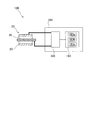
- FIG. 1 is an external perspective view of an oil property detection device according to a first embodiment of the present invention.
- FIG. 2 is a schematic cross-sectional view of the oil property detection device.
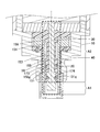
- FIG. 3 is a schematic cross-sectional view of a detection unit.
- FIG. 4 is a schematic view showing the configuration of the oil property detection device.
- FIG. 5 is a diagram showing a detection area and a non-detection area.
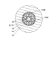
- FIG. 6 is a schematic cross-sectional view of the oil property detection device along the line VI-VI in FIG.
- FIG. 7 is a schematic cross-sectional view of an oil property detection device according to a second embodiment of the present invention.
- FIG. 8 is a schematic cross-sectional view of an oil property detection device according to a third embodiment of the present invention.
- FIG. 9 is a schematic cross-sectional view of an oil property detection device according to a fourth embodiment of the present invention.
- the fluid property detection device is, for example, attached to a pipe connected directly to a fluid pressure device such as a hydraulic cylinder that drives hydraulic fluid as a hydraulic fluid or connected to a hydraulic cylinder or the like, and detects the property of hydraulic fluid .
- the detection target fluid to be detected by the fluid property detection device is not limited to the hydraulic oil, and may be various liquids or gases such as lubricating oil, cutting oil, fuel, solvent, chemicals and the like.
- the fluid property detection device is the oil property detection device 100 that detects the property of hydraulic oil as the fluid to be detected will be described.
- the oil property detection device 100 includes a detection unit 101, a substrate unit 102 attached to the detection unit 101, and a cylindrical cylindrical cover 103 attached to the detection unit 101 and covering the substrate unit 102. And an end cover 104 that closes the opening of the cylindrical cover 103.
- the detection unit 101 includes a cylindrical outer electrode (second electrode) 20 and a rod-like inner electrode (first electrode) provided inside the outer electrode 20 so as to face the outer electrode 20.
- a housing 10 attached to the pipe 1 and holding the outer electrode 20 and the inner electrode 30, a mounting plate 107 fixed to the housing 10 with a screw or the like, and between the housing 10 and the outer electrode 20
- An outer spacer 40 provided to insulate the housing 10 from the outer electrode 20 and to define the position of the outer electrode 20 with respect to the housing 10, and provided between the outer electrode 20 and the inner electrode 30: the outer electrode 20 and the inner electrode
- the inner spacer 50 is an insulating member that insulates the housing 30 from the housing 10 and the inner electrode 30 and defines the position of the inner electrode 30 with respect to the housing 10; Comprising electrode 20 and the electrode cover 60 covering the front end portion of the inner electrode 30.
- a direction parallel to the central axis CL of the outer electrode 20 is referred to as an axial direction of the oil property detection device 100, and a direction orthogonal to the axial direction is referred to as a radial direction of the oil property detection device 100.
- the side on which the end cover 104 is disposed is referred to as the base end side of the oil property detection device 100, and the side opposite to the axial direction is referred to as the tip end side of the oil property detection device 100.
- the oil property detection device 100 is attached to the pipe 1 through which the hydraulic oil flows by screw connection, and detects the electrical property of the hydraulic oil by the detection unit 23 disposed inside the pipe 1.
- the detection unit 23 is configured by the tip of the outer electrode 20 and the inner electrode 30. The detection unit 23 protrudes from the housing 10 and is exposed to the hydraulic oil accommodated in the pipe 1.
- the board unit 102 includes a circuit board 181 and a board holding member 182 for holding the circuit board 181.
- the substrate holding member 182 is fixed to the mounting plate 107 of the detection unit 101 by a screw or the like.
- the housing 10 is formed of a conductive metal material, and has a mounting portion 111, a mounting portion 112, a nut portion 113, a cover receiving portion 114, and an insertion portion 115 in order from the distal end side to the proximal end side. ing.
- the mounting portion 111 has a cylindrical shape, and an external thread is formed on the outer periphery thereof, and is screwed into an internal thread formed on the inner periphery of the mounting hole 1 a of the pipe 1.
- the oil property detection device 100 is attached to the pipe 1 by inserting and screwing the attachment portion 111 into the attachment hole 1 a.
- the mounting portion 112 is a disc-shaped portion having an outer diameter larger than that of the mounting portion 111, and the surface on the tip end side is mounted on the opening peripheral portion of the mounting hole 1 a of the pipe 1.
- the placement unit 112 is not limited to being directly attached to the pipe 1 but may be attached to the pipe 1 via a backing plate.
- the nut portion 113 is formed in a hexagonal column shape. For this reason, the attachment portion 111 can be easily attached to the attachment hole 1a by rotating the nut portion 113 with a tool such as a spanner.
- the insertion portion 115 is cylindrical and is a portion inserted inside the cylindrical cover 103.
- the cover receiving portion 114 is a collar portion that protrudes radially outward from the proximal end of the nut portion 113, and the distal end surface of the cylindrical cover 103 abuts on the cover receiving portion 114.
- the cylindrical cover 103 is fixed to the insertion portion 115 with a screw or the like in a state where the insertion portion 115 is inserted into the cylindrical cover 103 and the tip end surface of the cylindrical cover 103 abuts on the cover receiving portion 114.
- the end cover 104 is fixed to the cylindrical cover 103 with a screw or the like while closing the opening on the proximal end side of the cylindrical cover 103.
- the substrate unit 102 is accommodated in an accommodation space defined by the end cover 104, the cylindrical cover 103 and the detection unit 101.
- a mounting plate housing portion 199 is provided as a space for housing the mounting plate 107.
- a large diameter accommodation portion 191 and a small diameter accommodation portion are sequentially arranged from the base end side toward the tip end side as a space for housing the electrode and the insulating member on the tip end side of the mounting plate housing portion 199 inside the housing 10
- An intermediate diameter accommodating portion 193 is formed at 192.
- the large-diameter housing portion 191, the small-diameter housing portion 192, and the middle-diameter housing portion 193 have circular cross-sectional shapes, and are provided coaxially. That is, the large diameter accommodation portion 191, the small diameter accommodation portion 192, and the middle diameter accommodation portion 193 are provided such that their central axes coincide with each other.
- the magnitude relationship between the inner diameter R1 of the large diameter storage portion 191, the inner diameter R2 of the small diameter storage portion 192, and the inner diameter R3 of the middle diameter storage portion 193 is R1> R3> R2.
- the inner diameter of the mounting plate housing portion 199 is formed larger than the inner diameter R1 of the large diameter housing portion 191, so between the inner peripheral surface of the mounting plate housing portion 199 and the inner peripheral surface of the large diameter housing portion 191, A step 198 is formed.
- the mounting plate 107 is fixed to the step 198 by a screw or the like.
- the outer electrode 20 is disposed coaxially with the inner electrode 30 so as to cover the outer periphery of the inner electrode 30.
- a gap is formed between the tip of the inner electrode 30 and the tip of the outer electrode 20 of the detection portion 23 so that hydraulic oil can enter.
- Each of the outer electrode 20 and the inner electrode 30 is electrically connected to a detection circuit 185 (see FIG. 4) mounted on the circuit board 181 via a wire (not shown).
- the outer electrode 20 is formed of a conductive metal material, and has a cylindrical outer electrode cylinder portion 121 and an outer electrode flange 122 projecting radially outward from the proximal end of the outer electrode cylinder portion 121.
- the outer spacer 40 is formed of a resin material having an insulating property, and an outer insulating flange projecting radially outward from the base end of the outer insulating cylindrical portion 141 which is a cylindrical insulating cylindrical portion and the outer insulating cylindrical portion 141 And 142.
- the inner electrode 30 is formed of a conductive metal material and has a cylindrical large diameter portion 131 provided at the tip and a cylindrical shape extending from the large diameter portion 131 toward the proximal end side of the oil property detection device 100 And a small diameter portion 132 of The inner spacer 50 is formed of a resin material having an insulating property, and an inner insulating flange 151 which is a cylindrical insulating cylinder and an inner insulating flange which protrudes radially outward from the base end of the inner insulating cylinder 151. And 152.
- the large diameter accommodating portion 191 of the housing 10 accommodates the outer insulating flange 142, the outer electrode flange 122, and the inner insulating flange 152 in a stacked arrangement in order from the distal end side to the proximal end side.
- the inner insulating flange 152, the outer electrode flange 122 and the outer insulating flange 142 are sandwiched between the stepped portion 195 of the housing 10 and the mounting plate 107.
- the outer insulating flange 142 and the inner insulating flange 152 define the axial position of the outer electrode 20.
- the outer peripheral surface of the inner insulating flange 152 and the outer peripheral surface of the outer insulating flange 142 are in contact with the inner peripheral surface of the large diameter accommodation portion 191. Therefore, the radial position of the outer spacer 40 and the inner spacer 50 is defined by the large diameter accommodation portion 191 of the housing 10.
- a base end of the inner electrode 30 is fixed to the mounting plate 107 and protrudes from the mounting portion 111 through the large diameter accommodation portion 191, the small diameter accommodation portion 192, and the middle diameter accommodation portion 193 from the attachment plate 107.
- the inner insulating cylindrical portion 151 extends in the axial direction from the inner insulating flange 152 to the tip end surface of the mounting portion 111.
- the distal end surface of the inner insulating cylindrical portion 151 is flush with the distal end surface of the mounting portion 111.
- the outer electrode cylinder portion 121 protrudes from the attachment portion 111 through the large diameter accommodation portion 191, the small diameter accommodation portion 192, and the middle diameter accommodation portion 193 from the outer electrode flange 122.
- the outer insulating tubular portion 141 extends in the axial direction from the outer insulating flange 142 to the step portion 196.
- the front end surface of the outer insulating cylindrical portion 141 is flush with the stepped portion 196.
- the inner electrode 30, the inner insulating cylindrical portion 151, the outer electrode cylindrical portion 121, and the outer insulating cylindrical portion 141 are stacked and arranged in the small diameter housing portion 192 of the housing 10 in the radial outward direction from the central axis side. Will be housed in a state.
- the outer insulating cylindrical portion 141 is disposed between the inner peripheral surface of the small diameter housing portion 192 of the housing 10 and the outer peripheral surface of the outer electrode cylindrical portion 121, and the inner peripheral surface of the outer electrode cylindrical portion 121 and the inner electrode
- the inner insulating cylindrical portion 151 is disposed between the outer peripheral surface of the inner shell 30 and the outer peripheral surface 30. Therefore, the positions of the outer electrode 20 and the inner electrode 30 in the radial direction are defined by the outer insulating cylindrical portion 141 and the inner insulating cylindrical portion 151.
- the inner insulating cylindrical portion 151 includes a first insulating cylindrical portion 157 disposed between the large diameter portion 131 of the inner electrode 30 and the outer electrode cylindrical portion 121, a small diameter portion 132 of the inner electrode 30 and an outer electrode cylindrical portion 121. And a second insulating cylindrical portion 158 disposed between the two.
- the inner side of the first insulating cylindrical portion 157 is a distal end side accommodating portion 157a that accommodates the large diameter portion 131 of the inner electrode 30, and the inner side of the second insulating cylindrical portion 158 is a base that accommodates the small diameter portion 132 of the inner electrode 30.
- the end side accommodation portion 158a is used.
- the outer diameter of the small diameter portion 132 of the inner electrode 30 is smaller than the outer diameter of the large diameter portion 131.
- the inner diameter of the outer electrode cylindrical portion 121 is constant over the entire length of the outer electrode cylindrical portion 121. Therefore, the thickness of the second insulating cylindrical portion 158 is larger (larger) than the thickness of the first insulating cylindrical portion 157.
- the inner diameter of the distal end side accommodating portion 157a is larger than the inner diameter of the proximal end side accommodating portion 158a, a stepped portion is formed between the inner peripheral surface of the distal end side accommodating portion 157a and the inner peripheral surface of the proximal end side accommodating portion 158a. 159 is formed. The stepped portion between the outer peripheral surface of the large diameter portion 131 and the outer peripheral surface of the small diameter portion 132 abuts on the stepped portion 159.
- the inner spacer 50 defines the axial position of the inner electrode 30.
- the outer spacer 40, the outer electrode 20, the inner spacer 50, and the inner electrode 30 are coaxially arranged, and their central axes are positioned so as to coincide with the central axis of the housing 10.
- the radial and axial positions of the outer electrode 20 and the inner electrode 30 are defined by the outer spacer 40 and the inner spacer 50.
- the outer diameter of the outer electrode flange 122 is set to a size smaller than the inner diameter of the large diameter accommodation portion 191, and the outer electrode flange 122 is prevented from contacting the large diameter accommodation portion 191.
- an outer first seal member 171 which is an annular O-ring for sealing between the housing 10 and the outer spacer 40, is provided.
- the outer first seal member 171 is disposed in an annular groove provided in the step portion 195.
- an outer second seal member 172 which is an annular O-ring for sealing between the outer spacer 40 and the outer electrode 20, is provided.
- the outer second seal member 172 is disposed in an annular groove provided in the outer insulating flange 142.
- the outer electrode cylindrical portion 121 and the outer insulating cylindrical portion 141 are not necessary to provide with a space for disposing the seal member. Therefore, the thickness of the outer electrode cylindrical portion 121 and the outer insulating cylindrical portion 141 can be reduced, and the oil property detection device 100 can be miniaturized.
- an inner first seal member (first seal member) 173 which is an annular O ring that seals between the inner spacer 50 and the outer electrode 20 is provided.
- the inner first seal member 173 is disposed in an annular groove 158 g provided in the second insulating cylindrical portion 158.
- the outer diameter of the inner spacer 50 may be increased, or the large diameter portion 131 may be provided. It is necessary to reduce the outer diameter of the When the outer diameter of the inner spacer 50 is increased, there arises a problem that the oil property detection device 100 increases in the radial direction. In addition, when the outer diameter of the large diameter portion 131 is reduced, the distance between the outer electrode 20 and the inner electrode 30 constituting the detection unit 23 is increased, which causes a problem that the detection accuracy is lowered. On the other hand, in the present embodiment, since the annular groove 158g is provided in the second insulating cylindrical portion 158, detection accuracy of the oil property detection device 100 can be improved, and the oil property detection device 100 can be miniaturized. Can be
- An inner second seal member (second seal member) which is an annular O ring for sealing between the inner electrode 30 and the inner spacer 50 between the large diameter portion 131 of the inner electrode 30 and the first insulating cylindrical portion 157 ) 174 is provided.
- the inner second seal member 174 is disposed in an annular groove 131 g provided in the large diameter portion 131. Thereby, the strength of the inner electrode 30 can be improved as compared with the case where an annular groove for disposing the seal member in the small diameter portion 132 is provided.
- the outer diameter of the small diameter portion 132 needs to be increased. In this case, since the distance between the inner electrode 30 and the outer electrode 20 becomes short, the floating capacitance may be increased. On the other hand, in the present embodiment, since the annular groove 131g is provided in the large diameter portion 131, the outer diameter of the small diameter portion 132 can be reduced. As a result, the stray capacitance can be reduced to improve the detection accuracy.
- the electrode cover 60 is inserted into the middle diameter accommodation portion 193 provided in the attachment portion 111 by press fitting.
- the fixing method is not limited to the press-in, and various fixing methods such as caulking and welding can be adopted.
- the electrode cover 60 is a bottomed cylindrical member, and has a disc-like bottom portion 161 and a side portion 162 rising from the outer peripheral edge of the bottom portion 161.
- the electrode cover 60 When the electrode cover 60 is inserted, the tips of the outer electrode 20 and the inner electrode 30 are covered by the electrode cover 60. Therefore, when attaching the oil property detection device 100 to the pipe 1, it is avoided that the tip (detection portion 23) of the outer electrode 20 and the inner electrode 30 directly contacts the outer peripheral surface of the pipe 1, the jig or the like. Since it can do, damage to the tip part (detection part 23) of an electrode can be prevented. The tip end portion (detection unit 23) of the electrode can be protected by the electrode cover 60, so that the highly reliable oil property detection device 100 can be provided.
- the electrode cover 60 and the outer electrode 20 are formed with a plurality of openings for introducing hydraulic oil to the inside.
- the detection circuit 185 connected to the inner electrode 30 and the outer electrode 20 has a voltage value applied between the inner electrode 30 and the outer electrode 20, and the detection circuit 185 of the inner electrode 30 and the outer electrode 20.
- a voltage value is detected that correlates to the value of the current flowing therebetween.
- the voltage value detected by the detection circuit 185 is output to the control unit 183 mounted on the circuit board 181 as the electrical characteristic of the hydraulic oil.
- the control unit 183 is a microcomputer, which is a property value of the hydraulic oil based on a voltage value which is an electrical characteristic between the tip of the outer electrode 20 and the tip of the inner electrode 30 constituting the detection unit 23.
- the arithmetic unit 183 a is a so-called central processing unit (CPU), and the storage unit 183 b is a non-volatile memory such as a rewritable EEPROM.
- the control unit 183 outputs the calculation result of the calculation unit 183a to an external control device (not shown) disposed outside the oil property detection device 100.
- Arithmetic unit 183a calculates the capacitance between inner electrode 30 and outer electrode 20 based on the detection result of detection circuit 185, and calculates the relative permittivity of the hydraulic fluid based on the calculated capacitance. Do. In addition, the calculation unit 183a calculates the resistance between the inner electrode 30 and the outer electrode 20 based on the detection result of the detection circuit 185, and calculates the conductivity of the hydraulic fluid based on the calculated resistance. . Thus, in the oil property detection device 100, the property of the hydraulic oil present in the gap between the inner electrode 30 and the outer electrode 20 is detected.
- an area in which the outer peripheral surface of the inner electrode 30 and the inner peripheral surface of the outer electrode 20 are exposed to the working oil from the tip end surface of the inner insulating cylindrical portion 151 in the axial direction Is set as the detection area A1.
- the non-detection area A2 an area proximal to the axial direction with respect to the detection area A1 is set.
- the total capacitance C between the inner electrode 30 and the outer electrode 20 detected by the detection circuit 185 is not detected in addition to the capacitance Ce between the inner electrode 30 and the outer electrode 20 in the detection area A1.
- the capacitance between the inner electrode 30 and the outer electrode 20 in the region A2 is included as the stray capacitance Cr.
- the air gap portion 153 is provided.
- the void portion 153 is formed between the inner electrode 30 and the outer electrode 20 in the non-detection area A2, which is an area not exposed to the hydraulic oil.
- the air gap portion 153 is formed by a concave portion 154 provided in the inner insulating cylindrical portion 151.
- the concave portion 154 is a lightening portion where the outer peripheral surface side of the inner insulating cylindrical portion 151 is opened.
- the recessed portion 154 is provided along the circumferential direction of the inner insulating cylindrical portion 151 over the entire circumference of the outer peripheral surface of the inner insulating cylindrical portion 151.
- a cylindrical gap 153 is defined by the bottom surface of the recess 154, the pair of side surfaces (tip surface and base surface) of the recess 154, and the inner peripheral surface of the outer electrode cylinder portion 121.
- the air gap portion 153 is a space in which the insulating member and the electrode do not exist, that is, a space in which the air having a low relative permittivity (approximately 1) is present.
- the inner spacer 50 As a material of the inner spacer 50, a petroleum-based resin material having a relative permittivity of 3 to 5 is employed. Therefore, the stray capacitance Cr can be reduced by forming the void portion 153 in which the resin material does not exist. As described above, according to the present embodiment, since the ratio of the stray capacitance Cr to the total capacitance C detected between the inner electrode 30 and the outer electrode 20 can be reduced, the electrostatic property by the oil property detection device 100 can be reduced. The detection accuracy of the capacitance Ce can be enhanced.
- the processability is better than in the case of forming a recess having an opening on the inner peripheral surface side.
- the processability is better than when the recessed portion is formed intermittently along the circumferential direction.
- the recess 154 is provided on the proximal side of the inner first seal member 173.
- the inner first seal member 173 can prevent the hydraulic oil from invading the recess 154, and therefore, can prevent an increase in the floating capacity Cr due to the hydraulic oil infiltrating into the recess 154.
- the inner spacer 50 has a distal end side holding portion 155 provided on the distal end side of the concave portion 154 and a proximal end side holding portion 156 provided on the proximal end side of the concave portion 154.
- the tip side holding portion 155 contacts each of the inner electrode 30 and the outer electrode 20 and defines the distance between the inner electrode 30 and the outer electrode 20.
- the proximal holding portion 156 is in contact with each of the inner electrode 30 and the outer electrode 20, and defines the distance between the inner electrode 30 and the outer electrode 20.
- Each holding portion (155, 156) supports the inner electrode 30 and the outer electrode 20 so that the inter-electrode distance between the inner electrode 30 and the outer electrode 20 does not become a predetermined distance or less.
- the outer electrode 20 can be prevented from being inclined with respect to the central axis of the housing 10 or displaced in the radial direction, and the distance between the outer electrode 20 and the inner electrode 30 can be prevented from being reduced. As a result, the insulation between the inner electrode 30 and the outer electrode 20 in the air gap 153 can be secured.
- the inner spacer 50 is provided with a recess 154, which forms an air gap 153 between the inner electrode 30 and the outer electrode 20 in the non-detection area A2 not exposed to the hydraulic fluid.
- the recess 154 is provided over the entire circumference of the inner insulating cylindrical portion 151 .
- the plurality of recessed portions 154B are provided at equal intervals in the circumferential direction of the inner insulating cylindrical portion 151, and are defined by the inner peripheral surface of the outer electrode 20 and the inner peripheral surface of the recessed portion 154B.
- a plurality of void portions 153B are formed.
- the same operation effect as a 1st embodiment is produced.
- the case where the recessed portion 154 is provided over the entire circumference of the inner insulating cylindrical portion 151 is preferable in terms of processability.
- the concave portion 154 is provided as the lightening portion to form the void portion 153 .
- a through hole 154C radially formed between the outer peripheral surface and the inner peripheral surface of the inner insulating cylindrical portion 151 is formed as the lightening portion.
- the through holes 154 ⁇ / b> C are opened on the outer peripheral surface side and the inner peripheral surface side of the inner insulating cylindrical portion 151.
- the gap 153C is defined by the inner peripheral surface of the through hole 154C, the inner peripheral surface of the outer electrode cylindrical portion 121, and the outer peripheral surface of the small diameter portion 132 of the inner electrode 30.
- the inner circumferential surface of the outer electrode cylindrical portion 121 and the outer circumferential surface of the small diameter portion 132 of the inner electrode 30 are in contact with each other between the through hole 154C and the through hole 154C adjacent to each other.
- An inter-hole holding portion 160 is provided which defines the distance between them. Since the outer electrode 20 and the inner electrode 30 can be supported on both sides in the radial direction of the air gap 153C, the positioning accuracy of the outer electrode 20 and the inner electrode 30 can be further improved.
- the through holes 154 ⁇ / b> C are opened on the outer peripheral surface side and the inner peripheral surface side of the inner insulating cylindrical portion 151, so that the through holes 154 ⁇ / b> C can be easily processed from the outside of the inner insulating cylindrical portion 151.
- the recess 154 is formed on the outer peripheral surface of the inner insulating cylindrical portion 151 in the first embodiment.
- the concave portion 154D is formed on the inner peripheral surface of the inner insulating cylindrical portion 151 in the fourth embodiment.
- the recess 154D extends to the axial proximal end surface of the inner spacer 50.
- the recess 154D can be processed from the proximal end side of the inner spacer 50.
- the inner peripheral surface side of the inner insulating cylindrical portion 151 is opened in the concave portion 154D. Therefore, the gap 153D is defined by the bottom surface of the recess 154D, the pair of side surfaces of the recess 154D, and the outer peripheral surface of the small diameter portion 132 of the inner electrode 30.
- the same operation effect as a 1st embodiment is produced.
- the case where the recessed portion 154 is formed on the outer peripheral side of the inner insulating cylindrical portion 151 is preferable in terms of processability.
- recessed part 154D can abbreviate
- the shapes of the outer electrode 20, the inner electrode 30, the outer spacer 40, and the inner spacer 50 are not limited to the shapes of the above embodiment, and various shapes can be adopted.
- the inner electrode 30 may be configured to include a large diameter portion 131 and a small diameter portion 132 in a cylindrical shape.
- Modification 2 instead of the cylindrical outer electrode 20 and the rod-shaped inner electrode 30, the present invention is applied to an oil property detection device including a flat plate-like first electrode and a flat plate-like second electrode provided opposite to the first electrode. It can also be applied.
- the configuration of the lightening portion for forming the void portion is not limited to the above embodiment.
- the lightening portion of the inner spacer 50 which is an insulating member, may be configured by separating the inner insulating cylindrical portion 151 and the inner insulating flange 152.
- the space may be formed by dividing the inner spacer 50 in the axial direction and bringing the concave portions as lightening portions provided in each of the pair of divided spacers into contact with each other.
- the void portion is defined only by the inner peripheral surfaces of the pair of recesses.
- the oil property detection device 100 is a fluid property detection device that detects the property of hydraulic oil (a fluid to be detected), and is provided opposite to the first electrode (inner electrode 30) and the first electrode (inner electrode 30). Between the first electrode (inner electrode 30), the first electrode (inner electrode 30) and the second electrode (outer electrode 20), and the first electrode (inner electrode 30) and the second electrode (outer electrode 20). And an inner spacer (insulation member) 50 which insulates the first electrode (inner electrode 30) and the second electrode (outer electrode) in the non-detection area A2 not exposed to the hydraulic oil.
- a lightening portion (concave portions 154, 154B, 154D, and a through hole 154C) for forming the air gap portions 153, 153B, 153C, 153D is provided between them and 20).
- the air gaps 153, 153B, 153C, 153D are provided between the first electrode (inner electrode 30) and the second electrode (outer electrode 20) in the non-detection area A2, the air gaps 153, 153B, The stray capacitance Cr is reduced as compared with the case where 153C and 153D are not provided. As a result, the detection accuracy of the capacitance Ce by the oil property detection device 100 can be improved.
- the first electrode is a rod-shaped inner electrode 30, the second electrode is a cylindrical outer electrode 20, and the inner electrode 30 and the outer electrode 20 are provided coaxially with each other.
- the spacer 50 has a cylindrical inner insulating cylindrical portion (insulating cylindrical portion) 151 disposed between the inner electrode 30 and the outer electrode 20, and the inner insulating cylindrical portion 151 has a light-cut portion (recessed portions 154 and 154B). , 154D, and through holes 154C).
- the oil property detection device 100 further includes an inner first seal member (first seal member) 173 provided between the inner insulating cylindrical portion 151 and the outer electrode 20 and sealing between the inner spacer 50 and the outer electrode 20.
- the lightening portions are opened on the outer peripheral surface side of the inner insulating cylindrical portion 151, and are provided on the proximal side of the inner first seal member 173.
- the outer peripheral surface side of the inner insulating cylindrical portion 151 is opened in the lightening portion (concave portions 154 and 154B and the through hole 154C), for example, only the inner peripheral surface side is opened when the outer peripheral surface side is not open.
- the workability is better than when the opening is open.
- the inner first seal member 173 can prevent hydraulic fluid from entering the gaps 153, 153B, 153C, and therefore prevents an increase in stray capacitance Cr due to hydraulic fluid entering the gaps 153, 153B, 153C. it can.
- a lightening portion (concave portion 154) is provided over the entire circumference of the outer peripheral surface of the inner insulating cylindrical portion 151.
- the lightening portion (recessed portion 154) is provided over the entire circumference of the outer peripheral surface of the inner insulating cylindrical portion 151, the lightening portion is intermittently provided along the circumferential direction of the inner insulating cylindrical portion 151. Processability is better than when forming.
- the lightening portion penetrates between the outer peripheral surface and the inner peripheral surface of the inner insulating cylindrical portion 151.
- the lightening portion (through hole 154C) is opened on the outer peripheral surface side and the inner peripheral surface side of the inner insulating cylindrical portion 151, for example, when the outer peripheral surface side is not opened, for example, Processability is better than when only the surface side is opened.
- the inner spacer 50 is provided on the tip side of the lightening parts (recesses 154, 154B, 154D, and the through hole 154C), and contacts each of the inner electrode 30 and the outer electrode 20.
- the inner electrode 30 and the outer electrode are provided on the proximal side with respect to the distal end side holding portion 155 for defining the distance between the electrode 30 and the outer electrode 20, and the lightening portions (recesses 154, 154B, 154D, through holes 154C). 20, and has a proximal end holding portion 156 which contacts each other and defines the distance between the inner electrode 30 and the outer electrode 20.
- the oil property detection device 100 further includes an inner second seal member (second seal member) 174 provided between the inner electrode 30 and the inner spacer 50 and sealing between the inner electrode 30 and the inner spacer 50, A cylindrical large diameter portion 131 provided at the distal end, and a cylindrical small diameter portion 132 having an outer diameter smaller than that of the large diameter portion 131 and extending from the large diameter portion 131 toward the base end; , And the inner insulating cylindrical portion 151 has a first insulating cylindrical portion 157 disposed between the large diameter portion 131 and the outer electrode 20, and a smaller diameter portion 132 that is thicker than the first insulating cylindrical portion 157.
- second seal member second seal member
- the second insulating tubular portion 158 disposed between the first and second outer electrodes 20, and the first inner seal member 173 is disposed in the annular groove 158g provided in the second insulating tubular portion 158, and the second inner tubular member
- the seal member 174 is at the large diameter portion 131 It is disposed in an annular groove 131g to be kicked.
- the annular groove 158g in which the inner first seal member 173 is disposed is provided in the second insulating cylinder portion 158, the annular groove in which the inner first seal member 173 is disposed is provided in the first insulating cylinder portion 157.
- the strength of the inner spacer 50 can be improved as compared with the case where the Further, since the annular groove 131g in which the inner second seal member 174 is disposed is provided in the large diameter portion 131, the inner side is provided inside compared to the case where the annular groove in which the inner second seal member 174 is disposed is provided in the small diameter portion 132.
- the strength of the electrode 30 can be improved.
Landscapes
- Chemical & Material Sciences (AREA)
- Chemical Kinetics & Catalysis (AREA)
- Electrochemistry (AREA)
- Physics & Mathematics (AREA)
- Health & Medical Sciences (AREA)
- Life Sciences & Earth Sciences (AREA)
- Analytical Chemistry (AREA)
- Biochemistry (AREA)
- General Health & Medical Sciences (AREA)
- General Physics & Mathematics (AREA)
- Immunology (AREA)
- Pathology (AREA)
- Investigating Or Analyzing Materials By The Use Of Electric Means (AREA)
Abstract
流体性状検出装置100は、作動油等の検出対象流体の性状を検出する流体性状検出装置であって、第1電極30と、第1電極30に対向して設けられる第2電極20と、第1電極30と第2電極20との間に設けられ第1電極30と第2電極20とを絶縁する絶縁部材50と、を備え、絶縁部材50には、検出対象流体に露出していない領域A2における第1電極30と第2電極20との間に空隙部153を形成するための肉抜き部154が設けられる。
Description
本発明は、流体性状検出装置に関する。
JP2009-25185Aには、管状の外側電極と、棒状の内側電極と、内側電極を絶縁樹脂を介して保持すると共に、外側電極と接続又は一体に形成される導電性の電極保持部材と、を備えた電気伝導度計測器が開示されている。絶縁樹脂(モールド樹脂)は、内側電極と、外側電極に接続又は一体に形成される電極保持部材と、の間の空間に充填され、電極間を絶縁する。
検出対象流体に露出する検出部である外側電極の先端部と内側電極の先端部との間の静電容量を検出する検出装置では、検出部以外の電極間の静電容量が浮遊容量として加算される。このため、検出部以外の電極間にモールド樹脂が隙間なく充填されてしまうと、電極間で検出される静電容量に占める浮遊容量の割合が大きくなり、検出精度が低下してしまうという問題がある。
本発明は、流体性状検出装置の検出精度を向上させることを目的とする。
本発明のある態様によれば、検出対象流体の性状を検出する流体性状検出装置であって、第1電極と、第1電極に対向して設けられる第2電極と、第1電極と第2電極との間に設けられ第1電極と第2電極とを絶縁する絶縁部材と、を備え、絶縁部材には、検出対象流体に露出していない領域における第1電極と第2電極との間に空隙部を形成するための肉抜き部が設けられる。
<第1実施形態>
以下、図面を参照して、本発明の第1実施形態に係る流体性状検出装置について説明する。
以下、図面を参照して、本発明の第1実施形態に係る流体性状検出装置について説明する。
流体性状検出装置は、例えば、作動油を作動流体として駆動する油圧シリンダ等の流体圧機器に直接、または、油圧シリンダ等に接続される配管に取り付けられ、作動油の性状を検出するものである。なお、流体性状検出装置の検出対象となる検出対象流体は、作動油に限定されず、潤滑油や切削油、燃料、溶媒、化学薬品といった種々の液体や気体であってもよい。以下では、流体性状検出装置が検出対象流体として作動油の性状を検出するオイル性状検出装置100である場合について説明する。
図1及び図2に示すように、オイル性状検出装置100は、検出ユニット101と、検出ユニット101に取り付けられる基板ユニット102と、検出ユニット101に取り付けられ基板ユニット102を覆う円筒状の円筒カバー103と、円筒カバー103の開口を塞ぐ端部カバー104と、を有する。
図2に示すように、検出ユニット101は、筒状の外側電極(第2電極)20と、外側電極20に対向するように外側電極20の内側に設けられる棒状の内側電極(第1電極)30と、配管1に取り付けられ、外側電極20及び内側電極30を保持する筐体10と、筐体10にねじ等により固定される取付板107と、筐体10と外側電極20との間に設けられ筐体10と外側電極20とを絶縁するとともに筐体10に対する外側電極20の位置を規定する外側スペーサ40と、外側電極20と内側電極30との間に設けられ外側電極20と内側電極30とを絶縁し、かつ、筐体10と内側電極30とを絶縁するとともに筐体10に対する内側電極30の位置を規定する絶縁部材である内側スペーサ50と、筐体10に取り付けられ、外側電極20及び内側電極30の先端部を覆う電極カバー60と、を備える。
以下では、外側電極20の中心軸CLに平行な方向をオイル性状検出装置100の軸方向と称し、この軸方向に直交する方向をオイル性状検出装置100の径方向と称する。また、端部カバー104が配置される側をオイル性状検出装置100の基端側と称し、軸方向の反対側をオイル性状検出装置100の先端側と称する。
オイル性状検出装置100は、作動油が内部を流れる配管1にねじ結合により取り付けられ、配管1の内側に配置される検出部23によって作動油の電気的特性を検出する。検出部23は、外側電極20及び内側電極30の先端部により構成される。検出部23は、筐体10から突出し、配管1に収容される作動油に露出する。
基板ユニット102は、回路基板181と、回路基板181を保持する基板保持部材182と、を備える。基板保持部材182は、検出ユニット101の取付板107にねじ等により固定される。
筐体10は、導電性を有する金属材料から形成され、先端側から基端側に向かって順に、取付部111、載置部112、ナット部113、カバー受け部114、挿入部115を有している。取付部111は、円筒状であり、外周に雄ねじが形成され、配管1の取付孔1aの内周に形成された雌ねじに螺合する。取付部111が取付孔1aに挿入、螺着されることにより、オイル性状検出装置100が配管1に取り付けられる。
載置部112は、取付部111よりも外径が大きい円板状の部分であり、先端側の面が配管1の取付孔1aの開口周縁部に載置される。なお、載置部112は、直接、配管1に取り付ける場合に限らず、当て板を介して配管1に取り付けてもよい。
ナット部113は、六角柱形状に形成される。このため、ナット部113をスパナ等の工具により回転させることで、取付部111を取付孔1aに容易に取り付けることができる。
挿入部115は、円筒状であり、円筒カバー103の内側に挿入される部分である。カバー受け部114は、ナット部113の基端から径方向外方に突出する鍔部であり、円筒カバー103の先端面が当接される。
挿入部115が円筒カバー103に挿入され、円筒カバー103の先端面がカバー受け部114に当接した状態で、ねじ等により円筒カバー103が挿入部115に固定される。
端部カバー104は、円筒カバー103の基端側の開口を塞いだ状態で、円筒カバー103にねじ等により固定される。基板ユニット102は、端部カバー104、円筒カバー103及び検出ユニット101により画成される収容空間に収容される。
筐体10の内側には、取付板107を収容する空間として取付板収容部199が設けられる。また、筐体10の内側における取付板収容部199よりも先端側には、電極や絶縁部材を収容する空間として、基端側から先端側に向かって順に、大径収容部191、小径収容部192、中径収容部193が形成される。
大径収容部191、小径収容部192及び中径収容部193は、その断面形状が円形状であり、同軸上に設けられる。すなわち、大径収容部191、小径収容部192及び中径収容部193は、それぞれの中心軸が一致するように設けられる。大径収容部191の内径R1、小径収容部192の内径R2、中径収容部193の内径R3の大小関係は、R1>R3>R2である。
大径収容部191の内径R1が小径収容部192の内径R2よりも大きく形成されるため、大径収容部191の内周面と小径収容部192の内周面との間には、段部195が形成される。中径収容部193の内径R3が小径収容部192の内径R2よりも大きく形成されるため、中径収容部193の内周面と小径収容部192の内周面との間には、段部196が形成される。
取付板収容部199の内径は、大径収容部191の内径R1よりも大きく形成されるため、取付板収容部199の内周面と大径収容部191の内周面との間には、段部198が形成される。取付板107は、ねじ等により段部198に固定される。
図3に示すように、外側電極20は、内側電極30の外周を覆うようにして内側電極30と同軸上に配置される。検出部23を構成する内側電極30の先端部と外側電極20の先端部との間には、作動油が浸入可能な隙間が形成される。外側電極20及び内側電極30のそれぞれは、配線(不図示)を介して、回路基板181に実装される検出回路185(図4参照)に電気的に接続される。
外側電極20は、導電性を有する金属材料から形成され、円筒状の外側電極筒部121と、外側電極筒部121の基端部から径方向外方に突出する外側電極フランジ122と、を有する。外側スペーサ40は、絶縁性を有する樹脂材料から形成され、円筒状の絶縁筒部である外側絶縁筒部141と、外側絶縁筒部141の基端部から径方向外方に突出する外側絶縁フランジ142と、を有する。
内側電極30は、導電性を有する金属材料から形成され、先端に設けられる円柱状の大径部131と、大径部131からオイル性状検出装置100の基端側に向かって延在する円柱状の小径部132と、を有する。内側スペーサ50は、絶縁性を有する樹脂材料から形成され、円筒状の絶縁筒部である内側絶縁筒部151と、内側絶縁筒部151の基端部から径方向外方に突出する内側絶縁フランジ152と、を有する。
筐体10の大径収容部191には、先端側から基端側に向かって順に、外側絶縁フランジ142、外側電極フランジ122、及び内側絶縁フランジ152が積層配置された状態で収容される。
内側絶縁フランジ152、外側電極フランジ122及び外側絶縁フランジ142は、筐体10の段部195と取付板107との間で挟まれる。したがって、外側絶縁フランジ142及び内側絶縁フランジ152により、外側電極20の軸方向の位置が規定される。
内側絶縁フランジ152の外周面及び外側絶縁フランジ142の外周面が大径収容部191の内周面に接触している。したがって、筐体10の大径収容部191により、外側スペーサ40及び内側スペーサ50の径方向の位置が規定される。
内側電極30は、基端部が取付板107に固着され、取付板107から大径収容部191、小径収容部192、中径収容部193を通って、取付部111から突出する。
内側絶縁筒部151は、内側絶縁フランジ152から取付部111の先端面まで軸方向に延在する。内側絶縁筒部151の先端面は、取付部111の先端面と面一とされる。
外側電極筒部121は、外側電極フランジ122から大径収容部191、小径収容部192、中径収容部193を通って、取付部111から突出する。
外側絶縁筒部141は、外側絶縁フランジ142から段部196まで軸方向に延在する。外側絶縁筒部141の先端面は、段部196と面一とされる。
筐体10の小径収容部192には、中心軸側から径方向外方に向かって順に、内側電極30、内側絶縁筒部151、外側電極筒部121、外側絶縁筒部141が積層配置された状態で収容される。
このように、筐体10の小径収容部192の内周面と外側電極筒部121の外周面との間に外側絶縁筒部141が配置され、外側電極筒部121の内周面と内側電極30の外周面との間に内側絶縁筒部151が配置される。したがって、外側絶縁筒部141及び内側絶縁筒部151により、外側電極20及び内側電極30の径方向の位置が規定される。
内側絶縁筒部151は、内側電極30の大径部131と外側電極筒部121との間に配置される第1絶縁筒部157と、内側電極30の小径部132と外側電極筒部121との間に配置される第2絶縁筒部158と、を有する。
第1絶縁筒部157の内側は、内側電極30の大径部131を収容する先端側収容部157aとされ、第2絶縁筒部158の内側は、内側電極30の小径部132を収容する基端側収容部158aとされる。内側電極30の小径部132の外径は、大径部131の外径よりも小さい。また、外側電極筒部121の内径は外側電極筒部121の全長に亘って一定である。このため、第2絶縁筒部158の肉厚は、第1絶縁筒部157の肉厚よりも厚い(大きい)。
先端側収容部157aの内径は、基端側収容部158aの内径よりも大きいため、先端側収容部157aの内周面と基端側収容部158aの内周面との間には、段部159が形成される。この段部159に、大径部131の外周面と小径部132の外周面との間の段部が当接する。したがって、内側スペーサ50により、内側電極30の軸方向の位置が規定される。
外側スペーサ40、外側電極20、内側スペーサ50及び内側電極30は、同軸上に配置され、それらの中心軸が、筐体10の中心軸と一致するように位置決めされる。上述したように、外側電極20及び内側電極30の径方向及び軸方向の位置が、外側スペーサ40及び内側スペーサ50によって規定される。これにより、内側電極30及び外側電極20を筐体10にねじ等で固定する固定作業を容易に行うことができる。また、内側電極30と外側電極20との距離を一定に保ち、オイル性状検出装置100の検出精度を維持することができる。
外側電極フランジ122の外径は、大径収容部191の内径よりも小さい寸法に設定され、外側電極フランジ122が大径収容部191に接触することが防止される。
段部195と外側絶縁フランジ142との間には、筐体10と外側スペーサ40との間をシールする環状のOリングである外側第1シール部材171が設けられる。外側第1シール部材171は、段部195に設けられた環状溝に配置される。外側絶縁フランジ142と外側電極フランジ122との間には、外側スペーサ40と外側電極20との間をシールする環状のOリングである外側第2シール部材172が設けられる。外側第2シール部材172は、外側絶縁フランジ142に設けられた環状溝に配置される。
これにより、外側電極筒部121及び外側絶縁筒部141に、シール部材を配置するためのスペースを設ける必要がない。したがって、外側電極筒部121及び外側絶縁筒部141の厚みを小さくでき、オイル性状検出装置100の小型化を図ることができる。
第2絶縁筒部158と外側電極筒部121との間には、内側スペーサ50と外側電極20との間をシールする環状のOリングである内側第1シール部材(第1シール部材)173が設けられる。内側第1シール部材173は、第2絶縁筒部158に設けられる環状溝158gに配置される。これにより、第1絶縁筒部157にシール部材を配置するための環状溝を設ける場合に比べて、内側スペーサ50の強度を向上できる。
仮に、強度を確保するために第1絶縁筒部157の肉厚を大きくした上で第1絶縁筒部157に環状溝を設ける場合、内側スペーサ50の外径を大きくしたり、大径部131の外径を小さくしたりする必要が生じる。内側スペーサ50の外径を大きくすると、径方向にオイル性状検出装置100が大きくなるという問題が生じる。また、大径部131の外径を小さくすると、検出部23を構成する外側電極20と内側電極30との間の距離が大きくなり、検出精度が低下するという問題が生じる。これに対して、本実施形態では、第2絶縁筒部158に環状溝158gを設けたので、オイル性状検出装置100の検出精度を向上することができるとともに、オイル性状検出装置100の小型化を図ることができる。
内側電極30の大径部131と第1絶縁筒部157との間には、内側電極30と内側スペーサ50との間をシールする環状のOリングである内側第2シール部材(第2シール部材)174が設けられる。内側第2シール部材174は、大径部131に設けられる環状溝131gに配置される。これにより、小径部132にシール部材を配置するための環状溝を設ける場合に比べて、内側電極30の強度を向上できる。
仮に、強度を確保しつつ小径部132に環状溝を設ける場合、小径部132の外径を大きくする必要がある。この場合、内側電極30と外側電極20との間の距離が短くなるので、浮遊容量が増加する問題が生じる。これに対して、本実施形態では、大径部131に環状溝131gを設けたので、小径部132の外径を小さくすることができる。その結果、浮遊容量を小さくして検出精度を向上することができる。
取付部111に設けられた中径収容部193には、電極カバー60が圧入により挿着される。なお、固定方法は圧入に限らず、かしめ加工や溶接等、種々の固定方法を採用できる。電極カバー60は、有底円筒状部材であり、円板状の底部161と、底部161の外周縁から立ち上がる側部162と、を有する。
電極カバー60が挿着されると、外側電極20及び内側電極30の先端部が電極カバー60により覆われる。このため、オイル性状検出装置100の配管1への取付作業の際、外側電極20及び内側電極30の先端部(検出部23)が、配管1の外周面や冶具等に直接接触することを回避できるので、電極の先端部(検出部23)の損傷を防止することができる。電極カバー60により電極の先端部(検出部23)を保護することができるので、信頼性の高いオイル性状検出装置100を提供できる。
電極カバー60及び外側電極20には、内部に作動油を導くための開口部が複数形成される。
図4に示すように、内側電極30及び外側電極20に接続される検出回路185は、内側電極30と外側電極20との間に印加された電圧値、及び内側電極30と外側電極20との間を流れる電流値に相関する電圧値を検出する。検出回路185で検出された電圧値は、作動油の電気的特性として、回路基板181に実装される制御部183へ出力される。
制御部183は、マイクロコンピュータであり、検出部23を構成する外側電極20の先端部と内側電極30の先端部との間の電気的特性である電圧値に基づいて、作動油の性状値である導電率及び比誘電率を演算する演算部183aと、演算部183aで演算された導電率及び比誘電率並びに検出部23で検出された電圧値を記憶可能な記憶部183bと、演算部183aで用いられるプログラム等を記憶するROMやRAM等の補助記憶部183cと、入出力インタフェース(不図示)と、を有する。演算部183aは、いわゆる中央演算処理装置(CPU)であり、記憶部183bは、書き換え可能なEEPROM等の不揮発性メモリである。制御部183は、演算部183aによる演算結果をオイル性状検出装置100の外部に配置される外部制御装置(不図示)に出力する。
演算部183aは、検出回路185での検出結果に基づいて、内側電極30と外側電極20との間の静電容量を演算し、演算した静電容量に基づいて作動油の比誘電率を演算する。また、演算部183aは、検出回路185での検出結果に基づいて、内側電極30と外側電極20との間の抵抗値を演算し、演算した抵抗値に基づいて作動油の導電率を演算する。このように、オイル性状検出装置100では、内側電極30と外側電極20との間の隙間に介在する作動油の性状が検出される。
図5に示すように、本実施形態では、内側絶縁筒部151の先端面から軸方向先端側であって、内側電極30の外周面及び外側電極20の内周面が作動油に露出する領域が、検出領域A1として設定される。非検出領域A2としては、検出領域A1よりも軸方向基端側の領域が設定される。
検出回路185で検出された内側電極30と外側電極20との間の全静電容量Cには、検出領域A1における内側電極30と外側電極20との間の静電容量Ceに加え、非検出領域A2における内側電極30と外側電極20との間の静電容量が浮遊容量Crとして含まれる。
このため、演算部183aは、全静電容量Cから浮遊容量Crを減算することにより、検出領域A1における内側電極30と外側電極20との間の静電容量Ceを演算する(Ce=C-Cr)。
ここで、全静電容量Cに占める浮遊容量Crの割合が大きいと、静電容量Ceの検出精度が低下してしまう。そこで、本実施形態では、全静電容量Cに占める浮遊容量Crの割合を小さくするために、空隙部153を設けている。
空隙部153は、作動油に露出していない領域である非検出領域A2における内側電極30と外側電極20との間に形成される。空隙部153は、内側絶縁筒部151に設けられた凹部154によって形成される。
図3、図5及び図6に示すように、凹部154は、内側絶縁筒部151の外周面側が開口された肉抜き部である。凹部154は、内側絶縁筒部151の周方向に沿って、内側絶縁筒部151の外周面の全周に亘って設けられる。このように、凹部154の底面と、凹部154の一対の側面(先端面及び基端面)と、外側電極筒部121の内周面と、によって円筒状の空隙部153が画成される。空隙部153は、絶縁部材及び電極が存在しない空間、すなわち比誘電率が低い(ほぼ1である)空気が存在する空間である。
内側スペーサ50の材料には、比誘電率が3~5の石油系の樹脂材料が採用される。このため、樹脂材料が存在しない空隙部153を形成することにより、浮遊容量Crを低減できる。このように、本実施形態によれば、内側電極30と外側電極20との間で検出される全静電容量Cに占める浮遊容量Crの割合を小さくできるので、オイル性状検出装置100による静電容量Ceの検出精度を高めることができる。
筒状の内側絶縁筒部151の外周面側を開口とする凹部154を形成することで、内周面側を開口とする凹部を形成する場合に比べて加工性がよい。また、筒状の内側絶縁筒部151の外周面の全周に亘って凹部154を形成しているため、周方向に沿って、断続的に凹部を形成する場合に比べて加工性がよい。
作動油の比誘電率は2~5であるため、凹部154に作動油が浸入してしまうと、その分浮遊容量増加してしまう。本実施形態では、図3及び図5に示すように、凹部154は、内側第1シール部材173よりも基端側に設けられる。内側第1シール部材173により、凹部154に作動油が浸入することを防止できるので、凹部154に作動油が浸入することに起因した浮遊容量Crの増加を防止できる。
内側スペーサ50は、凹部154よりも先端側に設けられる先端側保持部155と、凹部154よりも基端側に設けられる基端側保持部156と、を有する。先端側保持部155は、内側電極30及び外側電極20のそれぞれに接触し、内側電極30と外側電極20との間の距離を規定する。基端側保持部156は、内側電極30及び外側電極20のそれぞれに接触し、内側電極30と外側電極20との間の距離を規定する。各保持部(155,156)は、内側電極30と外側電極20との間の電極間距離が所定距離以下とならないように、内側電極30と外側電極20とを支持する。
これにより、外側電極20が筐体10の中心軸に対して傾いたり、径方向にずれたりすることを防止し、外側電極20と内側電極30との間の距離が小さくなることを防止できる。その結果、空隙部153における内側電極30と外側電極20との絶縁性を確保できる。
上述した第1実施形態によれば、次の作用効果を奏する。
内側スペーサ50には凹部154が設けられ、この凹部154によって、作動油に露出していない非検出領域A2における内側電極30と外側電極20との間に空隙部153が形成される。これにより、浮遊容量Crを低減することができるので、オイル性状検出装置100による静電容量Ceの検出精度を向上することができる。
<第2実施形態>
図7を参照して、本発明の第2実施形態に係るオイル性状検出装置100について説明する。以下では、上記第1実施形態と異なる点を中心に説明し、図中、上記第1実施形態で説明した構成と同一の構成または相当する構成には同一の符号を付して説明を省略する。
図7を参照して、本発明の第2実施形態に係るオイル性状検出装置100について説明する。以下では、上記第1実施形態と異なる点を中心に説明し、図中、上記第1実施形態で説明した構成と同一の構成または相当する構成には同一の符号を付して説明を省略する。
第1実施形態では、内側絶縁筒部151の全周に亘って凹部154が設けられる例について説明した。これに対して、第2実施形態では、複数の凹部154Bが内側絶縁筒部151の周方向に等間隔で設けられ、外側電極20の内周面と凹部154Bの内周面とにより画成される空隙部153Bが複数形成される。
このような第2実施形態によれば、第1実施形態と同様の作用効果を奏する。なお、第1実施形態のように内側絶縁筒部151の全周に亘って凹部154を設ける場合の方が、加工性の面で優れるため、好適である。
<第3実施形態>
図8を参照して、本発明の第3実施形態に係るオイル性状検出装置100について説明する。以下では、上記第1実施形態と異なる点を中心に説明し、図中、上記第1実施形態で説明した構成と同一の構成または相当する構成には同一の符号を付して説明を省略する。
図8を参照して、本発明の第3実施形態に係るオイル性状検出装置100について説明する。以下では、上記第1実施形態と異なる点を中心に説明し、図中、上記第1実施形態で説明した構成と同一の構成または相当する構成には同一の符号を付して説明を省略する。
第1実施形態では、空隙部153を形成するために肉抜き部として、凹部154を設ける例について説明した。これに対して、第3実施形態では、肉抜き部として、内側絶縁筒部151の外周面と内周面の間を径方向に貫通する貫通孔154Cが形成される。貫通孔154Cは、内側絶縁筒部151の外周面側及び内周面側のそれぞれが開口される。このため、貫通孔154Cの内周面と、外側電極筒部121の内周面と、内側電極30の小径部132の外周面と、によって空隙部153Cが画成される。
隣り合う貫通孔154Cと貫通孔154Cとの間には、外側電極筒部121の内周面及び内側電極30の小径部132の外周面のそれぞれに接触し、外側電極20と内側電極30との間の距離を規定する孔間保持部160が設けられる。空隙部153Cの径方向両側で外側電極20と内側電極30とを支持できるので、外側電極20及び内側電極30の位置決め精度をさらに向上できる。
このような第3実施形態によれば、第1実施形態と同様の作用効果を奏する。貫通孔154Cは、内側絶縁筒部151の外周面側及び内周面側のそれぞれが開口されているので、内側絶縁筒部151の外側から容易に加工することができる。
<第4実施形態>
図9を参照して、本発明の第4実施形態に係るオイル性状検出装置100について説明する。以下では、上記第1実施形態と異なる点を中心に説明し、図中、上記第1実施形態で説明した構成と同一の構成または相当する構成には同一の符号を付して説明を省略する。
図9を参照して、本発明の第4実施形態に係るオイル性状検出装置100について説明する。以下では、上記第1実施形態と異なる点を中心に説明し、図中、上記第1実施形態で説明した構成と同一の構成または相当する構成には同一の符号を付して説明を省略する。
第1実施形態では、内側絶縁筒部151の外周面に凹部154を形成する例について説明した。これに対して、第4実施形態では、内側絶縁筒部151の内周面に凹部154Dが形成される。凹部154Dは、内側スペーサ50の軸方向基端面まで延在している。凹部154Dは、内側スペーサ50の基端面側から加工することができる。
凹部154Dは、内側絶縁筒部151の内周面側が開口される。このため、凹部154Dの底面と、凹部154Dの一対の側面と、内側電極30の小径部132の外周面と、によって空隙部153Dが画成される。
このような第4実施形態によれば、第1実施形態と同様の作用効果を奏する。なお、第1実施形態のように内側絶縁筒部151の外周側に凹部154を形成する場合の方が、加工性の面で優れるため、好適である。また、凹部154Dは、内側絶縁筒部151の外周面側が開口されていないので、内側第1シール部材173を省略することができる。
次のような変形例も本発明の範囲内であり、変形例に示す構成と上述の実施形態で説明した構成を組み合わせたり、上述の異なる実施形態で説明した構成同士を組み合わせたり、以下の異なる変形例で説明する構成同士を組み合わせることも可能である。
(変形例1)
外側電極20、内側電極30、外側スペーサ40及び内側スペーサ50の形状は、上記実施形態の形状に限定されず、種々の形状を採用することができる。例えば、内側電極30が円柱形状の大径部131と小径部132とを備える例について説明したが、内側電極30は円筒形状の大径部131と小径部132とを備える構成にしてもよい。
外側電極20、内側電極30、外側スペーサ40及び内側スペーサ50の形状は、上記実施形態の形状に限定されず、種々の形状を採用することができる。例えば、内側電極30が円柱形状の大径部131と小径部132とを備える例について説明したが、内側電極30は円筒形状の大径部131と小径部132とを備える構成にしてもよい。
(変形例2)
筒状の外側電極20及び棒状の内側電極30に代えて、平板状の第1電極と、第1電極に対向して設けられる平板状の第2電極とを備えるオイル性状検出装置に本発明を適用することもできる。
筒状の外側電極20及び棒状の内側電極30に代えて、平板状の第1電極と、第1電極に対向して設けられる平板状の第2電極とを備えるオイル性状検出装置に本発明を適用することもできる。
(変形例3)
内側電極30及び外側電極20の軸長が短い場合、基端側保持部156を省略してもよい。
内側電極30及び外側電極20の軸長が短い場合、基端側保持部156を省略してもよい。
(変形例4)
空隙部を形成するための肉抜き部の構成は、上記実施形態に限定されない。例えば、絶縁部材である内側スペーサ50の肉抜き部は、内側絶縁筒部151と内側絶縁フランジ152とをセパレートすることにより構成してもよい。また、内側スペーサ50を軸方向に分割し、一対の分割スペーサのそれぞれに設けられた肉抜き部としての凹部同士を当接させることで、空隙部を形成してもよい。この場合、空隙部は、一対の凹部の内周面のみによって画成される。
空隙部を形成するための肉抜き部の構成は、上記実施形態に限定されない。例えば、絶縁部材である内側スペーサ50の肉抜き部は、内側絶縁筒部151と内側絶縁フランジ152とをセパレートすることにより構成してもよい。また、内側スペーサ50を軸方向に分割し、一対の分割スペーサのそれぞれに設けられた肉抜き部としての凹部同士を当接させることで、空隙部を形成してもよい。この場合、空隙部は、一対の凹部の内周面のみによって画成される。
以下、本発明の実施形態の構成、作用、及び効果をまとめて説明する。
オイル性状検出装置100は、作動油(検出対象流体)の性状を検出する流体性状検出装置であって、第1電極(内側電極30)と、第1電極(内側電極30)に対向して設けられる第2電極(外側電極20)と、第1電極(内側電極30)と第2電極(外側電極20)との間に設けられ第1電極(内側電極30)と第2電極(外側電極20)とを絶縁する内側スペーサ(絶縁部材)50と、を備え、内側スペーサ50には、作動油に露出していない非検出領域A2における第1電極(内側電極30)と第2電極(外側電極20)との間に空隙部153,153B,153C,153Dを形成するための肉抜き部(凹部154,154B,154D、貫通孔154C)が設けられる。
この構成では、非検出領域A2における第1電極(内側電極30)と第2電極(外側電極20)との間に空隙部153,153B,153C,153Dが設けられるので、空隙部153,153B,153C,153Dが設けられない場合に比べて浮遊容量Crが低減する。これにより、オイル性状検出装置100による静電容量Ceの検出精度を向上することができる。
オイル性状検出装置100は、第1電極が、棒状の内側電極30であり、第2電極が、筒状の外側電極20であり、内側電極30と外側電極20とは同軸上に設けられ、内側スペーサ50が、内側電極30と外側電極20との間に配置される筒状の内側絶縁筒部(絶縁筒部)151を有し、内側絶縁筒部151に、肉抜き部(凹部154,154B,154D、貫通孔154C)が設けられる。
この構成では、非検出領域A2における内側電極30と外側電極20との間に空隙部153,153B,153C,153Dが設けられるので、空隙部153,153B,153C,153Dが設けられない場合に比べて浮遊容量Crが低減する。これにより、オイル性状検出装置100による静電容量Ceの検出精度を向上することができる。
オイル性状検出装置100は、内側絶縁筒部151と外側電極20との間に設けられ内側スペーサ50と外側電極20との間をシールする内側第1シール部材(第1シール部材)173をさらに備え、肉抜き部(凹部154,154B、貫通孔154C)は、内側絶縁筒部151の外周面側が開口され、内側第1シール部材173よりも基端側に設けられる。
この構成では、肉抜き部(凹部154,154B、貫通孔154C)は、内側絶縁筒部151の外周面側が開口されているので、外周面側が開口されていない場合、たとえば、内周面側のみが開口されている場合に比べて加工性がよい。内側第1シール部材173により空隙部153,153B,153Cに作動油が浸入することを防止できるので、空隙部153,153B,153Cに作動油が浸入することに起因した浮遊容量Crの増加を防止できる。
オイル性状検出装置100は、肉抜き部(凹部154)が、内側絶縁筒部151の外周面の全周に亘って設けられる。
この構成では、肉抜き部(凹部154)が、内側絶縁筒部151の外周面の全周に亘って設けられるので、内側絶縁筒部151の周方向に沿って、断続的に肉抜き部を形成する場合に比べて加工性がよい。
オイル性状検出装置100は、肉抜き部(貫通孔154C)が、内側絶縁筒部151の外周面と内周面の間を貫通する。
この構成では、肉抜き部(貫通孔154C)は、内側絶縁筒部151の外周面側及び内周面側のそれぞれが開口されているので、外周面側が開口されていない場合、たとえば、内周面側のみが開口されている場合に比べて加工性がよい。
オイル性状検出装置100は、内側スペーサ50が、肉抜き部(凹部154,154B,154D、貫通孔154C)よりも先端側に設けられ、内側電極30及び外側電極20のそれぞれに接触し、内側電極30と外側電極20との間の距離を規定する先端側保持部155と、肉抜き部(凹部154,154B,154D、貫通孔154C)よりも基端側に設けられ、内側電極30及び外側電極20のそれぞれに接触し、内側電極30と外側電極20との間の距離を規定する基端側保持部156と、を有する。
この構成では、先端側保持部155及び基端側保持部156により、肉抜き部(凹部154,154B,154D、貫通孔154C)の軸方向両端側で内側電極30と外側電極20との間の距離を規定できるので、空隙部153,153B,153C,153Dにおける内側電極30と外側電極20との絶縁性を確保できる。
オイル性状検出装置100は、内側電極30と内側スペーサ50との間に設けられ内側電極30と内側スペーサ50との間をシールする内側第2シール部材(第2シール部材)174をさらに備え、内側電極30が、先端に設けられる円柱状の大径部131と、大径部131よりも外径が小さく、大径部131から基端側に向かって延在する円柱状の小径部132と、を有し、内側絶縁筒部151が、大径部131と外側電極20との間に配置される第1絶縁筒部157と、第1絶縁筒部157よりも肉厚が大きく、小径部132と外側電極20との間に配置される第2絶縁筒部158と、を有し、内側第1シール部材173が、第2絶縁筒部158に設けられる環状溝158gに配置され、内側第2シール部材174が、大径部131に設けられる環状溝131gに配置される。
この構成では、第2絶縁筒部158に内側第1シール部材173が配置される環状溝158gが設けられるので、第1絶縁筒部157に内側第1シール部材173が配置される環状溝が設けられる場合に比べて、内側スペーサ50の強度を向上できる。また、大径部131に内側第2シール部材174が配置される環状溝131gが設けられるので、小径部132に内側第2シール部材174が配置される環状溝が設けられる場合に比べて、内側電極30の強度を向上できる。
以上、本発明の実施形態について説明したが、上記実施形態は本発明の適用例の一部を示したに過ぎず、本発明の技術的範囲を上記実施形態の具体的構成に限定する趣旨ではない。
本願は2017年9月11日に日本国特許庁に出願された特願2017-174362に基づく優先権を主張し、この出願の全ての内容は参照により本明細書に組み込まれる。
Claims (7)
- 検出対象流体の性状を検出する流体性状検出装置であって、
第1電極と、
前記第1電極に対向して設けられる第2電極と、
前記第1電極と前記第2電極との間に設けられ前記第1電極と前記第2電極とを絶縁する絶縁部材と、を備え、
前記絶縁部材には、前記検出対象流体に露出していない領域における前記第1電極と前記第2電極との間に空隙部を形成するための肉抜き部が設けられる流体性状検出装置。 - 請求項1に記載の流体性状検出装置において、
前記第1電極は、棒状の内側電極であり、
前記第2電極は、筒状の外側電極であり、
前記内側電極と前記外側電極とは同軸上に設けられ、
前記絶縁部材は、前記内側電極と前記外側電極との間に配置される筒状の絶縁筒部を有し、
前記絶縁筒部に、前記肉抜き部が設けられる流体性状検出装置。 - 請求項2に記載の流体性状検出装置において、
前記絶縁筒部と前記外側電極との間に設けられ前記絶縁部材と前記外側電極との間をシールする第1シール部材をさらに備え、
前記肉抜き部は、前記絶縁筒部の外周面側が開口され、前記第1シール部材よりも基端側に設けられる流体性状検出装置。 - 請求項3に記載の流体性状検出装置において、
前記肉抜き部は、前記絶縁筒部の外周面の全周に亘って設けられる流体性状検出装置。 - 請求項3に記載の流体性状検出装置において、
前記肉抜き部は、前記絶縁筒部の外周面と内周面の間を貫通する流体性状検出装置。 - 請求項3に記載の流体性状検出装置において、
前記絶縁部材は、
前記肉抜き部よりも先端側に設けられ、前記内側電極及び前記外側電極のそれぞれに接触し、前記内側電極と前記外側電極との間の距離を規定する先端側保持部と、
前記肉抜き部よりも基端側に設けられ、前記内側電極及び前記外側電極のそれぞれに接触し、前記内側電極と前記外側電極との間の距離を規定する基端側保持部と、を有する流体性状検出装置。 - 請求項3に記載の流体性状検出装置において、
前記内側電極と前記絶縁部材との間に設けられ前記内側電極と前記絶縁部材との間をシールする第2シール部材をさらに備え、
前記内側電極は、
先端に設けられる円柱状の大径部と、
前記大径部よりも外径が小さく、前記大径部から基端側に向かって延在する円柱状の小径部と、を有し、
前記絶縁筒部は、
前記大径部と前記外側電極との間に配置される第1絶縁筒部と、
前記第1絶縁筒部よりも肉厚が大きく、前記小径部と前記外側電極との間に配置される第2絶縁筒部と、を有し、
前記第1シール部材は、前記第2絶縁筒部に設けられる環状溝に配置され、
前記第2シール部材は、前記大径部に設けられる環状溝に配置される流体性状検出装置。
Priority Applications (3)
| Application Number | Priority Date | Filing Date | Title |
|---|---|---|---|
| EP18854002.5A EP3683574B1 (en) | 2017-09-11 | 2018-05-14 | Fluid property detection device |
| US16/641,327 US11156578B2 (en) | 2017-09-11 | 2018-05-14 | Fluid-property detection device |
| CN201880053655.1A CN110998306B (zh) | 2017-09-11 | 2018-05-14 | 流体性质检测装置 |
Applications Claiming Priority (2)
| Application Number | Priority Date | Filing Date | Title |
|---|---|---|---|
| JP2017174362A JP6924106B2 (ja) | 2017-09-11 | 2017-09-11 | 流体性状検出装置 |
| JP2017-174362 | 2017-09-11 |
Publications (1)
| Publication Number | Publication Date |
|---|---|
| WO2019049430A1 true WO2019049430A1 (ja) | 2019-03-14 |
Family
ID=65634827
Family Applications (1)
| Application Number | Title | Priority Date | Filing Date |
|---|---|---|---|
| PCT/JP2018/018609 Ceased WO2019049430A1 (ja) | 2017-09-11 | 2018-05-14 | 流体性状検出装置 |
Country Status (5)
| Country | Link |
|---|---|
| US (1) | US11156578B2 (ja) |
| EP (1) | EP3683574B1 (ja) |
| JP (1) | JP6924106B2 (ja) |
| CN (1) | CN110998306B (ja) |
| WO (1) | WO2019049430A1 (ja) |
Families Citing this family (6)
| Publication number | Priority date | Publication date | Assignee | Title |
|---|---|---|---|---|
| JP6901355B2 (ja) | 2017-09-11 | 2021-07-14 | Kyb株式会社 | 流体性状検出装置 |
| US11678510B2 (en) | 2018-11-01 | 2023-06-13 | Boe Technology Group Co., Ltd. | Display panel, manufacturing method thereof, and display apparatus |
| WO2020179991A1 (ko) * | 2019-03-07 | 2020-09-10 | 주식회사 경동나비엔 | 액체 품질 측정기용 전극단자 어셈블리 및 그를 포함하는 액체 품질 측정기 |
| JP7705821B2 (ja) | 2022-03-31 | 2025-07-10 | カヤバ株式会社 | 流体性状監視システム、流体性状センサの検出値の異常の検出方法、及びプログラム |
| JP2024058431A (ja) * | 2022-10-14 | 2024-04-25 | 国立大学法人千葉大学 | 乳製品製造装置および乳製品製造方法 |
| EP4684202A2 (en) * | 2023-03-20 | 2026-01-28 | Watkins Manufacturing Corporation | Water quality sensing apparatus, modules, sub-assemblies, sensor cartridge, and components |
Citations (7)
| Publication number | Priority date | Publication date | Assignee | Title |
|---|---|---|---|---|
| JPH01120095A (ja) * | 1987-11-02 | 1989-05-12 | Murata Mfg Co Ltd | 多層回路基板 |
| US20040212375A1 (en) * | 2003-04-28 | 2004-10-28 | Detroit Diesel Corporation | Method and apparatus for stabilizing parasitic error capacitance in oil quality sensors |
| WO2006117033A1 (de) * | 2005-05-04 | 2006-11-09 | Maschinenfabrik Reinhausen Gmbh | Kapazitiver sensor zur erfassung des ölzustandes mit guardelektrode und heizung |
| JP2009025185A (ja) | 2007-07-20 | 2009-02-05 | Miura Co Ltd | 電気伝導度計測器 |
| JP2014142204A (ja) * | 2013-01-22 | 2014-08-07 | Denso Corp | 筒形電極、およびそれを用いた燃料性状センサ |
| WO2014126035A1 (ja) * | 2013-02-12 | 2014-08-21 | 株式会社堀場アドバンスドテクノ | 比抵抗測定回路、液体試料測定セル、比抵抗測定装置、液体試料管理方法及び液体試料管理システム |
| JP2017174362A (ja) | 2016-03-25 | 2017-09-28 | ヤマハ株式会社 | 設定装置及び方法 |
Family Cites Families (9)
| Publication number | Priority date | Publication date | Assignee | Title |
|---|---|---|---|---|
| US4931354A (en) | 1987-11-02 | 1990-06-05 | Murata Manufacturing Co., Ltd. | Multilayer printed circuit board |
| WO2006046325A1 (ja) * | 2004-10-29 | 2006-05-04 | Ngk Spark Plug Co., Ltd. | 液状態検知センサ |
| JP4430591B2 (ja) * | 2005-07-25 | 2010-03-10 | 日本特殊陶業株式会社 | ガスセンサ素子及びガスセンサ |
| JP5099068B2 (ja) * | 2009-04-23 | 2012-12-12 | 株式会社デンソー | ガスセンサ及びその製造方法 |
| JP5647188B2 (ja) * | 2011-07-21 | 2014-12-24 | 日本特殊陶業株式会社 | ガスセンサ |
| US8471343B2 (en) * | 2011-08-24 | 2013-06-25 | International Bussiness Machines Corporation | Parasitic capacitance reduction in MOSFET by airgap ild |
| JP2013167605A (ja) * | 2012-02-17 | 2013-08-29 | Denso Corp | 燃料性状検出装置 |
| US9719957B2 (en) * | 2013-01-08 | 2017-08-01 | Ngk Spark Plug Co., Ltd. | Gas sensor element and gas sensor |
| JP2015004651A (ja) * | 2013-06-24 | 2015-01-08 | 株式会社デンソー | 燃料性状センサ |
-
2017
- 2017-09-11 JP JP2017174362A patent/JP6924106B2/ja active Active
-
2018
- 2018-05-14 CN CN201880053655.1A patent/CN110998306B/zh active Active
- 2018-05-14 US US16/641,327 patent/US11156578B2/en active Active
- 2018-05-14 WO PCT/JP2018/018609 patent/WO2019049430A1/ja not_active Ceased
- 2018-05-14 EP EP18854002.5A patent/EP3683574B1/en active Active
Patent Citations (7)
| Publication number | Priority date | Publication date | Assignee | Title |
|---|---|---|---|---|
| JPH01120095A (ja) * | 1987-11-02 | 1989-05-12 | Murata Mfg Co Ltd | 多層回路基板 |
| US20040212375A1 (en) * | 2003-04-28 | 2004-10-28 | Detroit Diesel Corporation | Method and apparatus for stabilizing parasitic error capacitance in oil quality sensors |
| WO2006117033A1 (de) * | 2005-05-04 | 2006-11-09 | Maschinenfabrik Reinhausen Gmbh | Kapazitiver sensor zur erfassung des ölzustandes mit guardelektrode und heizung |
| JP2009025185A (ja) | 2007-07-20 | 2009-02-05 | Miura Co Ltd | 電気伝導度計測器 |
| JP2014142204A (ja) * | 2013-01-22 | 2014-08-07 | Denso Corp | 筒形電極、およびそれを用いた燃料性状センサ |
| WO2014126035A1 (ja) * | 2013-02-12 | 2014-08-21 | 株式会社堀場アドバンスドテクノ | 比抵抗測定回路、液体試料測定セル、比抵抗測定装置、液体試料管理方法及び液体試料管理システム |
| JP2017174362A (ja) | 2016-03-25 | 2017-09-28 | ヤマハ株式会社 | 設定装置及び方法 |
Non-Patent Citations (1)
| Title |
|---|
| See also references of EP3683574A4 |
Also Published As
| Publication number | Publication date |
|---|---|
| CN110998306A (zh) | 2020-04-10 |
| EP3683574B1 (en) | 2025-12-17 |
| EP3683574A4 (en) | 2021-06-23 |
| US20200386704A1 (en) | 2020-12-10 |
| CN110998306B (zh) | 2022-12-06 |
| JP2019049495A (ja) | 2019-03-28 |
| EP3683574A1 (en) | 2020-07-22 |
| JP6924106B2 (ja) | 2021-08-25 |
| US11156578B2 (en) | 2021-10-26 |
Similar Documents
| Publication | Publication Date | Title |
|---|---|---|
| JP6924106B2 (ja) | 流体性状検出装置 | |
| JP5592336B2 (ja) | ガスセンサ | |
| JP6901355B2 (ja) | 流体性状検出装置 | |
| JP5282049B2 (ja) | ガスセンサ | |
| US20080314748A1 (en) | Gas sensor | |
| JP6171251B2 (ja) | 圧力検出装置 | |
| JP6542707B2 (ja) | ガスセンサ | |
| US20190078955A1 (en) | Physical quantity sensor and method for manufacturing same | |
| JP7199907B2 (ja) | センサ | |
| JP6890061B2 (ja) | ガスセンサ | |
| CN107407654B (zh) | 气体传感器 | |
| JP7050646B2 (ja) | センサ | |
| JP7514265B2 (ja) | 流体性状センサ及び流体性状センサの製造方法 | |
| JP7050645B2 (ja) | センサ | |
| JP2012181127A (ja) | 圧力センサ | |
| JP6552914B2 (ja) | ガスセンサ | |
| JP2011047696A (ja) | ガスセンサユニット、固定具、及びガスセンサ取付け構造 | |
| JP5931701B2 (ja) | ガスセンサ | |
| JP2020067323A (ja) | センサ | |
| JPH0127586Y2 (ja) | ||
| JP7199908B2 (ja) | センサ | |
| JP2009008415A (ja) | オイルチェックセンサ | |
| JP2019027803A (ja) | 物理量センサ | |
| JP5567603B2 (ja) | ガスセンサ | |
| JP5981819B2 (ja) | センサ |
Legal Events
| Date | Code | Title | Description |
|---|---|---|---|
| 121 | Ep: the epo has been informed by wipo that ep was designated in this application |
Ref document number: 18854002 Country of ref document: EP Kind code of ref document: A1 |
|
| NENP | Non-entry into the national phase |
Ref country code: DE |
|
| ENP | Entry into the national phase |
Ref document number: 2018854002 Country of ref document: EP Effective date: 20200414 |
|
| WWG | Wipo information: grant in national office |
Ref document number: 2018854002 Country of ref document: EP |