WO2019049901A1 - Dispositif de production d'énergie hydraulique - Google Patents
Dispositif de production d'énergie hydraulique Download PDFInfo
- Publication number
- WO2019049901A1 WO2019049901A1 PCT/JP2018/032922 JP2018032922W WO2019049901A1 WO 2019049901 A1 WO2019049901 A1 WO 2019049901A1 JP 2018032922 W JP2018032922 W JP 2018032922W WO 2019049901 A1 WO2019049901 A1 WO 2019049901A1
- Authority
- WO
- WIPO (PCT)
- Prior art keywords
- water
- water flow
- rotor
- turbine rotor
- blade
- Prior art date
- Legal status (The legal status is an assumption and is not a legal conclusion. Google has not performed a legal analysis and makes no representation as to the accuracy of the status listed.)
- Ceased
Links
Images










Classifications
-
- F—MECHANICAL ENGINEERING; LIGHTING; HEATING; WEAPONS; BLASTING
- F03—MACHINES OR ENGINES FOR LIQUIDS; WIND, SPRING, OR WEIGHT MOTORS; PRODUCING MECHANICAL POWER OR A REACTIVE PROPULSIVE THRUST, NOT OTHERWISE PROVIDED FOR
- F03B—MACHINES OR ENGINES FOR LIQUIDS
- F03B11/00—Parts or details not provided for in, or of interest apart from, the preceding groups, e.g. wear-protection couplings, between turbine and generator
- F03B11/02—Casings
-
- F—MECHANICAL ENGINEERING; LIGHTING; HEATING; WEAPONS; BLASTING
- F03—MACHINES OR ENGINES FOR LIQUIDS; WIND, SPRING, OR WEIGHT MOTORS; PRODUCING MECHANICAL POWER OR A REACTIVE PROPULSIVE THRUST, NOT OTHERWISE PROVIDED FOR
- F03B—MACHINES OR ENGINES FOR LIQUIDS
- F03B3/00—Machines or engines of reaction type; Parts or details peculiar thereto
- F03B3/04—Machines or engines of reaction type; Parts or details peculiar thereto with substantially axial flow throughout rotors, e.g. propeller turbines
-
- Y—GENERAL TAGGING OF NEW TECHNOLOGICAL DEVELOPMENTS; GENERAL TAGGING OF CROSS-SECTIONAL TECHNOLOGIES SPANNING OVER SEVERAL SECTIONS OF THE IPC; TECHNICAL SUBJECTS COVERED BY FORMER USPC CROSS-REFERENCE ART COLLECTIONS [XRACs] AND DIGESTS
- Y02—TECHNOLOGIES OR APPLICATIONS FOR MITIGATION OR ADAPTATION AGAINST CLIMATE CHANGE
- Y02E—REDUCTION OF GREENHOUSE GAS [GHG] EMISSIONS, RELATED TO ENERGY GENERATION, TRANSMISSION OR DISTRIBUTION
- Y02E10/00—Energy generation through renewable energy sources
- Y02E10/20—Hydro energy
Definitions
- the present invention relates to, for example, a small-sized hydroelectric power unit installed in waterways, rivers, etc., and more particularly to a hydroelectric power unit capable of efficiently generating power even in a water flow with a small difference in elevation.
- Patent Literatures 1 and 2 describe a small-sized hydroelectric power generation device that uses natural water flow, such as a canal, without using the head of water and does not use the head of water.
- Patent Document 3 describes a hydroelectric power generation apparatus using a water drop.
- the canal In the hydroelectric power plant installed in the above-mentioned canal and the like, the canal generally has a small height difference and the velocity of the water flow is not necessarily large, so the number of rotations and torque of the rotor (impeller) is large
- the challenge is to raise
- the hydroelectric generator described in Patent Document 1 includes a duct whose outlet is larger than the inlet, and the rotor is disposed immediately after the inlet inside the duct, and the water flow with a high flow velocity flowing from the inlet is used. The rotational speed of the rotor is increased to enable efficient power generation.
- the hydroelectric generator using the head described in Patent Document 3 has the advantage that the power generation efficiency is high because the potential energy of water is large, but the hydroelectric generator is installed in the existing water channel or river with a small difference in elevation. It is difficult to install and the installation location is limited. Therefore, it is necessary to lay down concrete for forming a head at the bottom of the water channel or excavate the water channel to form a large head, and a large-scale civil engineering work is required. The cost is high.
- the present invention has been made in view of the above problems, and the water turbine rotor can be efficiently rotated to improve the power generation efficiency, and the installation is easy, even if the water flow has a small height difference and a small flow velocity.
- the purpose is to provide a hydroelectric power generation apparatus that can reduce costs.
- the water turbine rotor and the outer circumferential surface of the rotor support case are projected in the radial direction in a radial direction and fixed at a predetermined angle with respect to the rotation axis of the water turbine rotor, and the water flow is accelerated by the water turbine rotor.
- a plurality of water flow deflectors that can be deflected in the direction of rotation.
- the water flow is deflected to turn toward the water turbine rotor by the plurality of water flow deflection plates, and each blade is pushed in the acceleration direction by the deflected water flow.
- turning energy is added and the rotational speed and torque of the water turbine rotor are increased. Therefore, even when the hydroelectric generator according to the present invention is installed, for example, in a canal where the difference in elevation is small and the flow velocity of the water flow is small, the power generation efficiency can be enhanced.
- the water flow deflection plate is curved in a curved shape so that the water flow is curved toward the water turbine rotor.
- the water flow deflected by the plurality of water flow deflection plates is likely to be a swirling flow, so the rotational speed and torque of the water turbine rotor are further increased, and the power generation efficiency is further improved.
- the upstream water receiving surface of the blade is directed rearward in the rotational direction so that the inclination angle gradually increases toward the base end.
- the inclined surface is inclined, and the chord length of the blade is gradually increased from the proximal end to the distal end, and the blade is formed with an inclined portion inclined in the upstream direction at the distal end starting from the largest chord length.
- the projecting dimension of the water flow deflection plate in the radial direction is such that the tip of the water flow deflection plate extends to the vicinity of the maximum chord length.
- the deflected water flow after passing through the plurality of water flow deflectors strikes the inclined surface from the base end of the plurality of lift blades to the vicinity of the maximum chord length in a wide range, and the Coanda effect by the deflected water flow
- the lift type blade is strongly pushed in the rotational direction, and the rotation force and torque of the water turbine rotor are increased by the increase of the lift force.
- the tip portion of the blade is provided with an inclined portion which inclines in the upstream direction, and the inclined portion captures a water flow which is going to escape from the tip of the blade in the centrifugal direction.
- the flow out in the direction and the reaction pushes the tip of the blade in the direction of rotation, thereby increasing the rotational efficiency of the water turbine rotor. Therefore, the number of revolutions and the torque of the water turbine rotor are increased by the synergetic effect of the water flow deflection plate and the inclined portion, and the power generation efficiency is improved.
- the upstream water receiving surface of the blade is directed rearward in the rotational direction so that the inclination angle gradually increases toward the proximal end.
- the inclined surface is inclined, and the chord length of the blade is gradually increased from the proximal end to the distal end, and the blade is formed with an inclined portion inclined in the upstream direction at the distal end starting from the largest chord length.
- the radial projection size of the water flow deflection plate is a length such that the tip of the water flow deflection plate extends to the middle portion of the blade.
- the base side of the blade having a large inclination angle is strongly pressed in the rotational direction by the Coanda effect, so the radial projection dimension of the water flow deflection plate is set to a length extending to the middle portion of the blade.
- the rotation speed and torque of the water turbine rotor are increased, and the power generation efficiency is improved.
- the flow resistance is reduced by the amount by which the radial projection size of the water flow deflection plate is reduced, and the centrifugal half portion in which the chord length of each blade is gradually increased is opened, and the water receiving surface on the upstream side There is no risk of reducing the rotational speed and torque of the water turbine rotor since the water flow hits without
- the number of the water flow deflection plates is 3 to 16, and the inclination angle of each water flow deflection plate with respect to the rotation axis of the water turbine rotor is a water flow deflection plate The smaller the number is, the smaller the number is, and the smaller the number is, the larger the number does not exceed 45 degrees.
- the number of water flow deflection plates is within a range that does not reduce the flow velocity, and even when the number of water flow deflection plates is large, the flow resistance increases and the speed of the deflection water flow toward the water turbine rotor The lowering is suppressed, and when the number of the water flow deflection plates is small, the tilt angle can be increased to exhibit the water flow deflection effect.
- the rotor support case, the water turbine rotor, and the water flow deflection plate are surrounded by a cylindrical water transmission duct disposed in a water flow.
- the water flow that has flowed into the water conveyance duct from the upstream side flows neatly in the downstream direction, and the entire water flow in the water conveyance duct is deflected by the water flow deflection plate in the direction to accelerate the water turbine rotor effectively. Therefore, the rotational speed and torque of the water turbine rotor are increased, and the power generation efficiency is improved.
- the rotor support case has a fish shape having a large diameter on the upstream side and a gradually smaller diameter on the downstream side.
- the rotor support case long in the water flow direction is supported by a support in the water in the conduit for draining the stored water in the water storage tank of the head channel device or the water in the channel using a head, It projects radially outward on the outer peripheral surface on the downstream side in the longitudinal direction of the rotor support case, and inclines at a predetermined angle to the rotation axis of the water turbine rotor, and accelerates the water rotor in the water conduit And a plurality of water flow deflectors that can be deflected in the direction of rotation.
- the flow of water flowing in the water conduit is deflected by the plurality of water flow deflecting plates inclined and fixed to the rotor support case so as to turn toward the water turbine rotor.
- the blade is pushed in the speed increasing direction.
- turning energy is added to each blade in addition to the water position (falling) energy, and the rotation speed and torque of the water turbine rotor are increased. Therefore, the height of the water conduit for draining the water is limited by the installation space of the water storage tank, the depth of the water channel, and the like, and the power generation efficiency can be improved even when the drop energy of the water is small.
- the water channel is a water channel, and in this water channel, a weir plate is installed to raise the water level of the upstream water flow and form a head gap with the downstream water flow;
- the upper end portion of the water conduit is connected to the upper portion of the weir plate so as to communicate with the water conduction hole formed on the upper portion of the weir plate for discharging the upstream water whose water level has risen to the downstream side.
- the water turbine rotor can be efficiently rotated to improve the power generation efficiency.
- Example 1 of the hydraulic power unit concerning the present invention It is a side view of Example 1 of the hydraulic power unit concerning the present invention. It is the front view which looked at FIG. 1 from the upstream side. It is an enlarged front view of a single blade.
- FIG. 4 is an enlarged cross-sectional plan view taken along line IV-IV of FIG. 3;
- FIG. 5 is an enlarged cross-sectional plan view taken along line VV of FIG. 3;
- FIG. 6 is an enlarged cross-sectional plan view taken along line VI-VI of FIG. 3;
- Example 2 of the hydraulic power unit concerning the present invention It is the front view which looked at FIG. 7 from the upstream side. It is a front view of Example 3 of the hydraulic power unit concerning the present invention.
- Example 4 It is a perspective view which expands and shows a part of Example 4 of the hydraulic power unit based on this invention. It is a partially cutaway side view of Example 5 of the hydraulic power unit according to the present invention. It is a partially cutaway side view of Example 6 of the hydraulic power unit according to the present invention.
- FIG. 13 is an enlarged longitudinal front elevational view of FIG. 12 taken along line XIII-XIII. It is a vertical side view of Example 7 of the hydraulic power unit concerning the present invention.
- FIG. 15 is an enlarged cross-sectional plan view taken along line XV-XV of FIG. It is an enlarged side view of the principal part of a water turbine rotor. It is a perspective view of the principal part of the modification which curved the water flow deflection board.
- Example 8 of the hydraulic power unit concerning the present invention It is a longitudinal side view of Example 8 of the hydraulic power unit concerning the present invention. It is a longitudinal side view of Example 9 of the hydraulic power unit according to the present invention. It is a longitudinal side view of Example 10 of the hydraulic power unit concerning the present invention. It is a longitudinal side view of Example 11 of the hydraulic power unit concerning the present invention. It is a side view which shows the modification which made the water turbine rotor the drag type water turbine rotor.
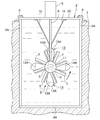
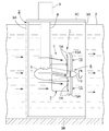
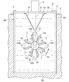
- FIGS. 1 and 2 show a first embodiment of a hydroelectric generator according to the present invention.
- the hydroelectric generator 1 is, for example, a relatively small one generated by the water flow of the agricultural water channel 2, and is supported It is installed in the water flow of the canal 2 in a form supported by the frame 3.
- the upstream side (left side in FIG. 1) of the water channel 2 is referred to as the front, and the downstream side (right side in FIG. 1) is referred to as the rear.
- the support frame 3 is connected to the lower ends of the four columns 3A spaced apart in the front, rear, left, and right directions with the ends of the four lower lateral ridges 3B facing in the front, rear, left and right directions.
- the face plate 3C By fixing the face plate 3C, it has a rectangular frame shape in which the four front and rear surfaces and the lower surface are open. As shown by the arrow in FIG. 1, water flowing from the upstream side to the downstream side in the canal 2 can pass through the rectangular frame-like support frame 3 without resistance.
- the upper and lower dimensions of the support frame 3 are slightly larger than the height of the water channel 2. Further, in the present embodiment, the lateral width of the support frame 3 is made substantially equal to the lateral width of the canal 2 by taking the case where the lateral width of the canal 2 is relatively small as an example. However, since the support frame 3 is fixed to the canal 2 by the fixture 4 described later, the support frame 3 should be installed in the canal 2 in an immobile state even if the canal 2 is wide. Can.
- the support frames 3 dropped into the canal 2 are fixed to the upper surfaces of the left and right wall surfaces of the canal 2 by fixtures 4 and 4 at a plurality of locations on the left and right sides of the top plate 3C.
- the hydroelectric power generation apparatus 1 includes a hollow rotor support case 5 that is long in the water flow direction and a water rotor 6 that is provided at the rear end of the rotor support case 5 and rotates counterclockwise in a front view. 6.
- a plurality of (eight sheets in this embodiment) water deflectors 7 fixed to the outer peripheral surface in the longitudinal direction (front-rear direction) of the rotor support case 5 in the front close to 6 and the upper surface of the rotor support case 5 near the front
- the lower end is fixed, the upper end is fitted in the upper surface plate 3C, and is fixed to the hollow case hanging support 8 facing in the vertical direction, and facing the case supporting support 8 at the center of the upper surface of the upper surface plate 3C.
- a generator 9 that generates electric power by being linked to the water turbine rotor 6.
- the water flow deflection plate 7 can be integrally molded with the rotor support case 5 when it is molded with synthetic resin, aluminum or the like.
- the lower end portion of the case support rod 8 is fixed to the left and right side surfaces of the middle portion, and the upper end portion is fixed to the lower surface of the upper surface plate 3C. It is held immobile in the central part of the inside.
- the case hanging support 8 has a fish-like cross section in plan view, which is thick in the left-right direction at the front and gradually becomes thinner toward the rear. The passing water flow is accelerated by the Coanda effect.
- the rotor support case 5 has a large diameter at the front and a gradually smaller diameter toward the rear, and has a shape similar to a fish-like tuna etc.
- the water flow from the front toward the rotor support case 5 is due to the Coanda effect
- a water flow that flows fast backward along the fish shape of the rotor support case 5 and travels to the vicinity of the base of a blade 13 described later in the water turbine rotor 6 is accelerated by the Coanda effect.
- a horizontal rotor shaft 11 directed in the front-rear direction with its rear end slightly protruded from the rear end of the rotor support case 5 is rotatably supported and accommodated by a bearing not shown. There is.
- the water turbine rotor 6 has a hub 12 fixed to the rear end of the rotor shaft 11 and a plurality of (four in the present embodiment) lift-type blades (bases in the center direction) fixed to the hub 12 at regular intervals.
- a blade 13 The hub 12 and the blade 13 are made of, for example, fiber reinforced synthetic resin (FRP), or a light metal such as aluminum or duralumin.
- FRP fiber reinforced synthetic resin
- the hub 12 may be omitted and the blade 13 may be directly fixed to the rear end of the rotor shaft 11.
- the front end portion of the rotor shaft 11 is, for example, similar to the hydraulic power generator described in Patent Document 1 described above, by means of transmission means (two bevel gears meshing with rotating axes orthogonal to each other) and transmission means By being linked to the generator 9 via a vertical transmission shaft (all not shown) rotated within the support rod 8, the rotor shaft 11 rotates clockwise with the water turbine rotor 6 in a front view direction.
- the generator 9 is driven to generate electric power.
- each blade 13 has a chord length gradually increasing from the base side toward the tip end portion and the tip end portion so that the water receiving area becomes larger toward the tip end portion.
- the rotation efficiency of the water turbine rotor 6 can be enhanced by forming the upstream inclined portion 13A which inclines forward, which is the upstream direction, to increase the effect of capturing the water flow.
- the maximum chord length 13B of the blade 13 is formed in the vicinity of the tip, and the upstream inclined portion 13A is formed at the tip with the maximum chord 13B as a base point.
- the upstream inclined portion 13A is tapered toward the tip, and the inclination angle is, for example, 35 degrees to 45 degrees.
- the cross-sectional shape of the blade 13 is such that the thickness on the front side in the rotational direction indicated by the arrow is thick and the thickness gradually decreases toward the rear end.
- the rear face is expanded in an arc shape, and the entire blade 13 is twisted at a predetermined angle with respect to the rotor shaft 11 to form a pitch angle, whereby the front face on the upstream side, which is the water receiving face, is directed outward in the rotational direction It is an inclined surface 13C that inclines.
- the inclination angle (angle of attack) of the inclined surface 13C is smaller at the tip end side of the blade 13 and gradually larger toward the base end.
- each blade 13 receives a water flow from the front, a lift is generated on each blade 13 and the water turbine rotor 6 rotates counterclockwise in a front view by the thrust acting in the rotation direction.
- the upstream direction inclined portion 13A is formed at the tip end portion of each blade 13, when the water turbine rotor 6 rotates, along the inclined surface 13C inclined to the rear side in the rotational direction, from the base end to the centrifugal direction Since a part of the water stream to be discharged is captured by the upstream inclined portion 13A and discharged in the diagonal centrifugal direction, the propulsive force in the rotational direction of the blade 13 is increased by the reaction, and the rotation speed and torque of the water turbine rotor 6 Is enhanced.
- the eight water flow deflectors 7 described above are provided on the outer peripheral surface in the longitudinal direction of the rotor support case 5 between the case support post 8 and the water turbine rotor 6 at equal intervals so as to project in the radial direction.
- the base end portion is fixed by inclining in the direction opposite to the rotation direction of the water turbine rotor 6 at a predetermined angle with respect to the rotation axis of 6.
- the axial width dimension of each water flow deflection plate 7 is approximately half the axial length of the rotor support case 5, and the radial projection dimension is the maximum chord length of the blade 13 at the tip end. The length extending to the vicinity of the portion 13B or the length extending to the vicinity of the base of the upstream inclined portion 13A.
- the inclination angle of each water flow deflection plate 7 with respect to the rotation axis of the water turbine rotor 6 is approximately 10 degrees, but this inclination angle is, for example, 5 degrees to 45 degrees depending on the number of water flow deflection plates 7 It is set within the range. That is, as the number of the water flow deflection plates 7 increases, the inclination angle is reduced and the number decreases, so that the water flow resistance plate 7 does not increase the water flow resistance and the speed of the deflection water flow toward the rotor does not decrease. Therefore, it is preferable to make the inclination angle gradually larger.
- the number of the water flow deflection plates 7 is preferably in the range of 3 to 16, preferably 6 to 12, in order to exert the water flow deflection effect without reducing the flow velocity.
- a plurality of water flow deflection plates 7 projecting in the radial direction with respect to the rotation axis of the water turbine rotor 6
- the direction in which the water flow accelerates the water turbine rotor 6 by the eight water flow deflectors 7, ie, the rotation direction of the water turbine rotor 6 It is deflected to pivot in the opposite direction.
- each water flow deflecting plate 7 strikes the inclined surface 13C in a wide range from the base end of the plurality of blades 13 to the vicinity of the maximum chord length 13B and rotates each blade 13 by lift force by the Coanda effect.
- turning energy is added to each blade 13 to increase the rotational speed and torque of the water turbine rotor 6.
- an upstream-facing inclined portion 13A that inclines toward the upstream direction is provided. Therefore, the water stream which is about to escape in the centrifugal direction from the tip of the blade 13 is captured by the upstream inclined portion 13A and flows out in the diagonal centrifugal direction opposite to the rotational direction, and the tip of the blade 13 It is pushed in the rotational direction, and the rotational efficiency of the water turbine rotor 6 is enhanced. Therefore, even when the flow velocity of the water flow in the canal 2 is small, the number of revolutions and the torque of the water turbine rotor 6 are increased by the synergetic effect of the water flow deflector 7 and the upstream inclined portion 13A, and the power generation efficiency is improved.
- FIG. 7 and 8 are side views of the second embodiment of the hydraulic power generation apparatus according to the present invention.
- symbol is attached
- the hydroelectric power generation apparatus is the same as the first embodiment except that a bent portion 7A bent in the direction opposite to the rotation direction of the water turbine rotor 6 is formed at the tip of the water flow deflection plate 7.
- the projection dimension in the radial direction of the water flow deflection plate 7 of the second embodiment is set such that the bent portion 7A extends to the vicinity of the maximum chord length portion 13B of the blade 13.
- each water flow deflection plate 7 Since the bent portion 7A bent in the direction opposite to the rotation direction of the water turbine rotor 6 is formed at the tip of the water flow deflection plate 7, each water flow deflection plate 7 The flow of water deflected by the fluid flow is suppressed from flowing in the centrifugal direction, and the amount and amount of water deflected in the direction opposite to the rotation direction of the water turbine rotor 6 are increased.
- FIG. 9 is a front view of a third embodiment of the hydroelectric power generation apparatus according to the present invention.
- symbol is attached
- the hydroelectric power generation apparatus has the radial projection dimensions of the plurality of water flow deflectors 7 having the same bending portion 7A as in the second embodiment, and the bending portion 7A is an intermediate portion of the blade 13, ie, the blade 13.
- the length extends to approximately half the length in the radial direction, and the inclination angle with respect to the rotation axis of the water turbine rotor 6 is larger than that of the water flow deflector 7 of the first and second embodiments (for example, 15 degrees).
- the projecting dimension of the water flow deflection plate 7 in the radial direction is a length extending to the middle part of the blade 13 and the inclination angle is large
- the water flow deflection plate 7 reverses the rotation direction of the water turbine rotor 6 Since the base side of the blade 13 is pushed in the rotational direction by the lift force by the Coanda effect by the water flow that is largely deflected to the same direction, the number of rotations and the torque of the water turbine rotor 6 increase and the power generation efficiency is improved.
- the flow resistance is reduced by the amount by which the radial projection dimension of the water flow deflection plate 7 is reduced, and the half of the centrifugal direction in which the chord length of each blade 13 is gradually increased is opened. Since the water flow strikes the receiving surface without resistance, there is no possibility of reducing the rotational speed and torque of the water turbine rotor 6.
- the bending part 7A may be abbreviate
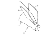
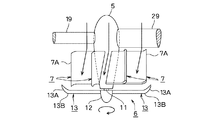
- FIG. 10 is an enlarged view of a portion of a hydroelectric power generation apparatus according to a fourth embodiment of the present invention, in which the water flow of each water flow deflection plate 7 of the first embodiment is opposite to the rotation direction of the water turbine rotor 6 It is curved in a curved shape so that it flows in a curved manner. In this way, the water flow deflected in the direction opposite to the rotation direction of the water turbine rotor 6 by each water flow deflection plate 7 is likely to become a swirling flow, so the inclined surfaces 13C of the plurality of blades 13 are effectively effective in the rotation direction. The rotation speed and torque of the water turbine rotor 6 are increased. Also in the water flow deflection plate 7 of the fourth embodiment, the bent portion 7A as in the second embodiment may be formed at the tip, and in this case, the generation effect of the swirling flow is enhanced.
- FIG. 11 is a side view of a fifth embodiment of the hydroelectric power generation apparatus according to the present invention.
- symbol is attached
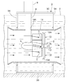
- the hydroelectric generator according to the fifth embodiment has a cylindrical shape in which the diameter of the upstream and downstream ends of the rotor support case 5, the water turbine rotor 6 and the plurality of water flow deflectors 7 are arranged in the water flow of the water channel 2. It is surrounded by the water duct 14 of the A plurality of locations on the outer peripheral surface of the water guiding duct 14 are fixed to the support columns 3A on the upstream side and the downstream side of the support frame 3.
- the case support rod 8 penetrates the opening 14A on the upper surface of the water guiding duct 14 while maintaining water tightness and protrudes upward.
- the water flow which has flowed into the water guiding duct 14 from the upstream side flows neatly in the downstream direction, and the entire water flow in the water guiding duct 14 effectively rotates the water turbine rotor 6 by the water flow deflecting plate 7. As it is deflected in the direction opposite to the direction, the rotational speed and torque of the water turbine rotor 6 are increased, and the power generation efficiency is improved.
- the flow velocity of the water flow passing through the water conveyance duct 14 becomes larger than the flow velocity of the water flow outside the water conduction duct 14 by the venturi effect.
- the flow velocity of the water flow deflected in the direction opposite to the rotation direction of the water turbine rotor 6, and the flow velocity of the deflected water flow after passing through the plurality of water flow deflection plates 7 also become large.
- the plurality of blades 13 are strongly pushed in the rotational direction by the lift force by the Coanda effect, the rotation speed and torque of the water turbine rotor 6 are increased, and the power generation efficiency is higher than that of the hydroelectric generator of each of the embodiments. improves.
- this may be made into a straight cylindrical thing.
- the hydroelectric power generation device 1 of the sixth embodiment is installed at a position where a slight height difference is formed in the riverbed 15 of the river, or at a position where the riverbed 15 is excavated slightly to form a height difference.
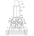
- the water conduit 16 in which the upstream side is the downward inclined portion 16A and the downstream side is the horizontal portion 16B is submerged in the water flow, It is fixed in an immobile state by a plurality of anchor members 17, 17 fixed to both side surfaces in the longitudinal direction so as to be separated from the riverbed 15, and the hydraulic power unit 1 is mounted on the horizontal portion 16 B of the water guiding duct 16.
- a rotor support case 5 similar to the example, a water turbine rotor 6, and a plurality of water flow deflecting plates 7 having a bent portion 7A at the tip end portion are installed in the duct. Note that the reason for placing the water guiding duct 16 away from the riverbed 15 is to prevent mud water, gravel, and the like from flowing into the water guiding duct 16.
- a filter 18 for preventing foreign matter in the water flow from flowing into the water guiding duct 16 is detachably attached by a screw or the like.
- the rotor support case 5 is fixed to the inner surface of the horizontal portion 16B of the water conduit 16 by fixing the outer end portions of the pair of case support arms 19, 19 whose inner end portions are fixed to both side surfaces thereof. It is located in the center of the house.
- the water guiding duct 16 also serves as a support of the present invention for supporting the rotor support case 5.
- the lower end portion of the long case support rod 20 is fixed to the front upper portion of the rotor support case 5 and penetrates the upper surface of the horizontal portion 16B of the water duct 16 to extend upward.
- the upper end portion is supported by an upper surface plate 21A of the generator support base 21 having a U-shape in a front view downward direction, whose lower end is fixed to the upper surface of the water guiding duct 16.
- a generator 9 is fixed to the upper surface plate 21A of the generator support base 21.
- This generator 9 is linked to transmission means accommodated in the case support rod 20 as in the embodiment described above, and the case support is supported. It is connected to the upper end of a vertical transmission shaft that is rotated in the crucible 20. As shown in FIG. 13, when the rotor shaft 11 rotates clockwise with the water rotor 6 in a front view, the generator 9 is driven to generate electric power.
- the height of the generator support 21 is set to an upper and lower dimension sufficiently separated from the water surface so as to prevent the generator 9 from being submerged.
- the water guiding duct 16 is installed on the small riverbed 15 having a height difference in the river, and the rotor support having the plurality of water flow deflecting plates 7 on the outer peripheral surface in the horizontal portion 16B of the water guiding duct 16
- the case 5 and the water turbine rotor 6 are accommodated. Therefore, the water flow flowing in the water conveyance duct 16 in an orderly manner is deflected in the direction opposite to the rotation direction of the water turbine rotor 6 by the plurality of water flow deflection plates 7, and the plurality of blades 13 rotate in the rotation direction by the Coanda effect. It is strongly pressed by Therefore, even if the flow is a gentle river, the rotational speed and torque of the water turbine rotor 6 are increased, and the power generation efficiency is improved.
- the water guiding duct 16 is omitted, and the support frame 3 and the like as in the first embodiment are installed on the riverbed 15, and the support frame 3 and the like support the case And the generator 9 can be supported. Further, in the case of the water guiding duct 16 which is entirely inclined downward and does not have the horizontal portion 16B, the rotor support case 5 having the water flow deflector 7 and the water turbine rotor 6 in the downward inclined portion 16A It can also be housed diagonally along the 16A.
- the hydroelectric generator is supported by the support frame 3 installed in the water channel 2, it is installed so as to simply straddle the water channel 2 without using the support frame 3.
- the hydroelectric generator may be suspended by a support.
- the number of the blades 13 of the water turbine rotor 6 is four in each of the above embodiments, the number of blades 13 is not limited to this, and it is needless to say
- the present invention can also be applied to a hydroelectric generator using a propeller-type water turbine rotor provided with a mold blade.
- the water flow deflection plate 7 may be inclined in the same direction as the rotation direction of the water turbine rotor, and even in this way, the swirling water flow deflected by the water flow deflection plate 7 Since the drag type blade is pushed in the rotational direction by this, the water turbine rotor can be accelerated to increase its rotational speed and torque.
- the generator 9 linked to the water turbine rotor 6 is installed outside the rotor support case 5, but the generator is accommodated in the rotor support case 5 and the generated power is You may take out outside via an electrical wiring.
- FIG. 14 and the subsequent figures show an embodiment in which the hydroelectric power generation apparatus 1 is disposed in the flowing water of the water fall channel device 22.
- the head channel 22 communicates with the water storage tank 23 having a funnel-shaped lower portion and a drainage hole 23A on the lower surface and the drainage hole 23A, and the upstream end is the lower surface of the water storage tank 23
- the hydropower generator 1 is attached to the reverse L-shaped water pipe 24 connected to the above, and the upper part of the water pipe 24.
- the water conduit 24 comprises a vertical pipe portion 24A and a horizontal pipe portion 24B whose lower end is connected to the ground G at the lower end so that the upper end of the upward elbow is detachably connected to the lower end thereof. Is attached to the vertical pipe portion 24A.
- the height of the water from the lower end of the water storage tank 23 to the horizontal pipe portion 24B is, for example, 1 to 3 m in consideration of the installation space and the like of the drop channel device 22. Water flowing out of the lower end of the horizontal pipe portion 24B flows down to a canal, a river or the like via a water channel (not shown).
- An upper lid 25 having a wire mesh for covering relatively large dust and the like from entering is disposed on the opening surface of the upper end of the water storage tank 23.
- a filter 18 for capturing fine dust and the like that has entered the water storage tank 23 is detachably attached to the upper end portion of the vertical pipe portion 24A.
- water drawn in from an irrigation canal, a drainage channel, a river, a lake, a reservoir, a reservoir, a dam, etc. is stored via the water supply pipe 26.
- the amount of water supplied to the water storage tank 23 is adjusted, for example, by a sluice valve (not shown) for flow rate adjustment provided at the water intake port of the water supply pipe 26, and the stored water is almost full It is supposed to be kept
- the water storage tank 23 and the water conduit 24 are stably supported by the ground G at the lower end and by a plurality of (for example, three or more) vertical support rods 27 whose upper ends are fixed to the outer peripheral surface of the funnel-shaped portion of the water storage tank 23 It is held.
- the hydroelectric power generation device 1 is disposed in a central portion near the downstream side of the vertical pipe portion 24A, and has a hollow rotor support case 5 long in the water flow direction (vertical direction), and the lower end of the rotor support case 5 in plan view.
- the water turbine rotor 6 rotates in the clockwise direction.
- a plurality of (eight in the present embodiment) water flow deflection plates 7 fixed to the outer peripheral surface in the longitudinal direction (vertical direction) of the rotor support case 5 and the upper side of the rotor support case 5
- the horizontal hollow transmission shaft receiving arm 29 is supported by a mounting bracket 28 whose left end is fixed to the right side and the right side passing through the vertical pipe 24A is fixed to the right side of the vertical pipe 24A.
- a generator 9 attached to the mounting bracket 28 and linked to the water turbine rotor 6 to generate electric power.
- the upper outer peripheral surface of the rotor support case 5 is vertical by the transmission shaft accommodation arm 29 and three horizontal case support arms 15 fixed to the inner surface of the vertical pipe portion 24A. It is stably and well supported by the pipe portion 24A.
- the transmission shaft receiving arm 29 and the case support arm 19 have a fish-shaped cross section in side view, which has a thick upper portion and gradually decreases downward, and passes through them. The water flow is made to accelerate.
- the rotor support case 5 has a tuna-like shape with a large diameter at the top and a gradually smaller diameter toward the bottom, and the water flow from the top toward the rotor support case 5 is shaped like a fish in the rotor support case 5 The velocity of the water flowing fast along the lower side and passing near the base of the blade 13 described later in the water turbine rotor 6 is increased.
- a rotor shaft 11 having a lower end protruding from the lower end of the rotor support case 5 and directed in the vertical direction (water flow direction) is rotatably supported and accommodated by a bearing (not shown). .
- the water turbine rotor 6 has a hub 12 fixed to the lower end portion of the rotor shaft 11 and a plurality of (four in the present embodiment) lift-type blades (the followings are fixed to the hub 12). And 13).
- the hub 12 and the blade 13 are made of, for example, a synthetic resin (including a fiber reinforced synthetic resin), a light metal such as aluminum (including an alloy thereof), or a metal material such as stainless steel or titanium.
- the upper end portion of the rotor shaft 11 is a transmission means (two bevel gears meshing with rotating axes orthogonal to each other), and a horizontal transmission shaft (not shown) rotated in the transmission shaft receiving arm 29 by the transmission means
- the generator 9 is driven to generate electric power by rotating the rotor shaft 11 in a counterclockwise direction in plan view with the water turbine rotor 6 in cooperation with the generator 9 via the.
- Each blade 13 is the same as that shown in FIGS.
- the rotor support case 5 in FIG. 7 is vertically oriented, and the water turbine rotor 6 is positioned downstream.
- each blade 13 receives a deflected water flow from above, the water turbine rotor 6 rotates counterclockwise in plan view by the reaction force (thrust) acting on each blade 13 in the rotational direction.
- the upstream direction inclined portion 13A is formed at the tip end portion of each blade 13, when the water turbine rotor 6 rotates, along the inclined surface 13C inclined to the rear side in the rotational direction, from the base end to the centrifugal direction Since a part of the water stream to be discharged is captured by the upstream inclined portion 13A and discharged in the oblique centrifugal direction, the reaction increases the thrust in the rotational direction of the blade 13, and the rotation speed and torque of the water turbine rotor 6 increase. Be enhanced.
- the eight water flow deflection plates 7 described above have outer peripheral surfaces in the vertical direction of the rotor support case 9 between the transmission shaft accommodation arm 13 and the case support arm 15 and the water turbine rotor 10.
- the water turbine rotor 6 In order to project in the radial direction and at a predetermined angle in the direction to accelerate the water turbine rotor 6, that is, in the direction opposite to the rotation direction of the water turbine rotor 6, with respect to the rotation axis of the water turbine rotor 6. The end is fixed.
- each water flow deflection plate 7 is, for example, approximately 1/2 of the length in the vertical direction of the rotor support case 5, and the projection dimension in the radial direction is, for example, a blade at the tip end
- the length is extended to the vicinity of the maximum chord length portion 13B of thirteen.
- the projection size of each water flow deflection plate 7 in the radial direction may be a length extending to the tip of the blade 13 or a length exceeding the tip.
- a bent portion 7A bent in the direction opposite to the rotation direction of the water turbine rotor 6 is formed at the tip of the water flow deflection plate 7.
- the rotor support case 5 is formed of synthetic resin or the like, the water flow deflection plate 7 can be integrally formed therewith.
- the inclination angle of each water flow deflection plate 7 with respect to the rotation axis of the water turbine rotor 6 is approximately 10 °, but this inclination angle ranges, for example, from 5 ° to 45 ° depending on the number of water flow deflection plates 7 It is set within. That is, as the number of the water flow deflectors 7 increases, the inclination angle decreases and the number decreases, so that the water flow resistance is not increased by the water flow deflector 7 and the velocity of the deflected water flow toward the water turbine rotor 6 is not reduced.
- the number of the water flow deflection plates 7 is, for example, 3 to 16, preferably 6 to 12 in accordance with the magnitude of the head of the water flow in order to exert the water flow deflection effect without lowering the flow velocity. That's good.
- each water flow deflection plate 7 strikes a wide range from the base end of the plurality of blades 13 to the vicinity of the maximum chord length 13B, and the waters of the deflected water flows along each blade 13 and the Coanda effect
- the lift in the rotational direction acting on the blade 13 is increased.
- each blade 13 is strongly pressed in the rotational direction (counterclockwise direction in plan view), and turning energy is added to each blade 13 in addition to the drop energy of the water, and their synergistic effect causes the water turbine rotor 6 to Speed and torque are increased.
- an upstream-facing inclined portion 13A that inclines toward the upstream direction is provided. Therefore, the water stream which is going to escape from the tip of the blade 13 in the centrifugal direction is captured by the upstream inclined portion 18A and flows out in the diagonal direction opposite to the rotation direction, and the tip of the blade 13 It is pushed in the rotational direction, and the rotational efficiency of the water turbine rotor 6 is enhanced.
- the height of the water conduit 3 is limited by the installation space of the water storage tank 23, etc., and even when the drop (position) energy of water is small, the synergistic effect of the water flow deflector 7 and the upstream inclined portion 13A Thus, the rotation speed and torque of the water turbine rotor 6 can be increased to improve the power generation efficiency.
- the bent portion 7A facing in the direction opposite to the rotation direction of the water turbine rotor 6 is formed at the tip of the water flow deflection plate 7, the water flow deflected by each water flow deflection plate 7 flows in the centrifugal direction. As a result, the amount and amount of water deflected in the direction opposite to the rotational direction of the water turbine rotor 6 are increased. As a result, the inclined surface 13C from the base end to the vicinity of the maximum chord length 13B in the plurality of blades 13 is strongly pushed in the rotational direction by the lift force by the Coanda effect, the rotation speed and torque of the water turbine rotor 6 become large, Efficiency is further improved.
- FIG. 17 shows a modification of the water flow deflector 7.
- each water flow deflector 7 is curved in a curved shape so that the water flow is curved in the direction opposite to the rotation direction of the water turbine rotor 6. It is In this case, the water flow deflected in the direction opposite to the rotation direction of the water turbine rotor 6 by the water flow deflection plates 7 is likely to become a swirling flow, and the plurality of blades 13 are effectively pushed in the rotation direction. The rotational speed and torque of the rotor 6 are increased.
- deviation plate 7 may be abbreviate
- FIG. 18 is a longitudinal side view of a hydraulic power generation system according to an eighth embodiment.
- symbol is attached
- the hydroelectric generator 1 of the eighth embodiment arranges the rotor support case 5 horizontally near the downstream side of the horizontal pipe portion 24B in the water conduit 24 of the down flow water channel device 22.
- the generator 9 is fixed to the upper surface of the upward transmission shaft receiving arm 29 attached to the upper surface of the rotor support case 5 via a mounting bracket 28.
- the water flow that has flowed into the horizontal pipe portion 24B is deflected by the plurality of water flow deflection plates 7 so as to turn in the direction opposite to the rotation direction of the water turbine rotor 6. Since the inclined surface 13C of the blade 13 is pushed in the rotational direction by the lift force by the Coanda effect, the number of rotations and the torque of the water turbine rotor 6 are increased. Therefore, even when the water drop from the water storage tank 23 to the horizontal pipe portion 24B can not be increased, the power generation efficiency can be improved.
- FIG. 19 is a longitudinal side view of a hydraulic power generation system according to a ninth embodiment of the present invention.
- the same members as those in Examples 7 and 8 described above are denoted by the same reference numerals, and the detailed description thereof will be omitted.
- the hydroelectric generator according to the ninth embodiment is provided with a drainage hole 23A to which the filter 18 is attached at the lower end portion of the outer peripheral surface of the water storage tank 23 installed on the ground G, and is inclined in the vertical direction at the lower part of the water storage tank 23
- the upstream end of the water pipe 24 having a small head difference is connected to communicate with the drainage hole 23A, and the hydraulic power unit 1 similar to the eighth embodiment is attached to the downstream end of the water pipe 24. It is.
- the water flow flowing in the water conduit 24 is deflected by the plurality of water flow deflection plates 7 so as to turn in the direction opposite to the rotation direction of the water turbine rotor 6,
- the 13 inclined surfaces 13C are pushed in the rotational direction by the lift force by the Coanda effect. Therefore, even if the water guiding pipe 3 has a small head difference and a slow water flow velocity, the rotation speed and torque of the water turbine rotor 6 are increased, and the power generation efficiency is improved.
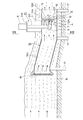
- FIG. 20 is a vertical cross-sectional side view of a hydraulic power generation system according to a tenth embodiment of the present invention, which is an example in which the hydraulic power generation system 1 is installed, for example, in a water channel 30 for agriculture.
- the same members as those in each embodiment described above are denoted by the same reference numerals, and the detailed description thereof will be omitted.
- the weir 30 is provided with a weir plate 20 for blocking the water flow, raising the water level on the upstream side, and forming a head difference with the water flow on the downstream side.
- the hydroelectric generator 1 is attached to the side surface (left side surface of the figure).
- the anchor plate 31 and the hydraulic power generation device 1 are integrally connected in advance, and in a state where they are unitized, they can be lifted and installed on the water channel 30 by a crane or the like.
- a plurality of lifting brackets 32 such as eyebolts that can be lifted by hooking a crane or the like are attached to the central portion of a later-described later-described later holding plate 34 fixed to the upper end of the holding plate 31. .
- the upper and lower dimensions of the weir plate 31 are formed substantially the same as the depth of the canal 30 so that the lower end reaches the bottom of the canal 30, and the width dimension is also formed substantially the same width as the canal 30.
- a plurality of triangular reinforcing plates are arranged at the upper end of the gutter plate 31 so as to cross the water channel 30 and are straddled on the upper surface thereof, and a gutter plate holding plate 34 fixed by a plurality of fasteners 33 and 33 is arranged in the width direction. It is fixed with 34A, and the weir plate 31 is held immobile in the water channel 30 by the weir plate holding plate 34 and the reinforcing plate 34A.
- a water conduction hole 35 is provided in the upper part of the weir plate 31 to allow the upstream water whose water level has been raised to flow out to the downstream side via a water conduction pipe 24 described later.
- a mesh-like filter 18 for preventing foreign matter from flowing into the water passage 35 is detachably attached to the upper portion of the upstream wall surface of the weir plate 31 by a plurality of holders 36, 36.
- a water passage hole 37 for adjusting the water level on the upstream side is provided at the lower end portion of the weir plate 31, and a part of the upstream water blocked by the weir plate 31 is passed through the water passage hole 37.
- the size and the number of the water flow holes 37 are appropriately determined depending on the depth, the flow rate, and the like of the water channel 30.
- the lower end of the weir plate 20 may be separated from the bottom surface of the water passage 30, and a gap formed between them may be a water flow hole. When the water volume of the canal 30 is small, such a water flow hole 37 may be omitted and the entire upstream water flow may be blocked by the weir plate 31.
- a water conduit 24 for flowing out the upstream water, which raised the water level of the irrigation channel 30, to the downstream side is attached in communication with the water conduit 35
- the upper elbow pipe portion 24C bolted to the weir plate 31 with a flange so that the right end upper portion of the water conduit 24 opens in the upstream direction of the irrigation conduit 30 and the open end communicates with the water conduit 34;
- a vertical pipe portion 24D continuous with the downward opening of the pipe portion 24C, and a lower elbow pipe portion 24E connected to the lower end of the vertical pipe portion 24D via a flange and having a lower left end opening in the downstream direction of the irrigation channel 30 ing.
- the rotor support case 5 is disposed in the middle portion of the vertical pipe portion 24D so as to face the vertical direction, and the water turbine rotor 6 at the lower end is rotated counterclockwise in plan view.
- the plurality of water flow deflectors 7 are attached to be inclined in the direction opposite to the rotation direction of the water turbine rotor 6.
- the generator 9 is separated from the water surface on the downstream side so as not to be submerged.
- the deflection water flow causes the blades 13 to be pushed in the rotational direction by the lift force by the Coanda effect, and turning energy is added to each blade 13 outside the drop energy of the water, so the vertical dimension of the water conduit 24 is made large. Even if the head is not increased so much, the rotational speed and torque of the water turbine rotor 6 are increased, and the power generation efficiency is improved.
- the water flow is blocked by the weir plate 31 to raise the water level on the upstream side, and a head is formed in the canal 30 to generate electricity. Therefore, the energy of the water stream to be used is large and the power generation efficiency is high, as compared with the hydroelectric power generation using the naturally flowing water stream of the canal 30.
- the canal 30 partially blocks the canal 30 and raises the water level to form a head, water volume in the canal 30 is small and the water rotor in the water conduit 24 is low even if the water level is low. Can efficiently rotate and enhance power generation efficiency.
- a drop can be formed in the canal 30 simply by holding the canal 30 by the weir plate 31, a large-scale civil engineering work for constructing a concrete weir and the like as in the prior art becomes unnecessary. It can be reduced.
- the lower portion of the lower elbow pipe portion 24E can be extended downstream, and the rotor support case 5 can be installed in the same manner as in FIG.
- the generator 9 may be covered by a waterproof cover or the like, or the transmission shaft accommodation arm 29 may be extended upward to separate the generator 9 from the water surface.
- FIG. 21 is a vertical cross-sectional side view of a hydraulic power generation system according to an eleventh embodiment of the present invention, which is another embodiment in which the hydraulic power generation system 1 is installed in the water channel 19.
- symbol is attached
- the inclined water conduit 38 which inclines downward in the downstream direction of the water channel 30 is attached to the upper part of the gutter plate 31 similar to the tenth embodiment, and the middle portion of the inclined water conduit 38
- the rotor support case 5 similar to that of the embodiment is installed so that the generator 14 is not submerged.
- the water flow of the irrigation channel 30 is not completely stopped by the weir plate 31, but the upstream water with the water level raised is the water conduit 24, As it flows downstream via the water supply holes 38 and the water holes 37, there is no risk of affecting the water right of the downstream side.
- the plurality of hydroelectric power generators 1 when the water channel width of the irrigation channel 30 is relatively large, the plurality of hydroelectric power generators 1 can be arranged in the width direction on the weir plate 31 having a large width dimension. Power generation efficiency can be improved.
- the hydroelectric power generation device 1 according to the tenth and eleventh embodiments can be installed in water and sewage, industrial waterways, rivers with a relatively small river width, and the like in addition to the agricultural waterways 30.
- the present invention is not limited to the above-described embodiments, and various modifications and changes as described below can be made without departing from the scope of the present invention.
- the number of the blades 13 of the water turbine rotor 6 is four in each of the above embodiments, the number of the blades 13 is not limited to this, and it is needless to say that a water turbine provided with a lift type blade in which the upward inclined portion 13A is not formed at the tip end
- the present invention can also be applied to a hydroelectric generator using a rotor.
- the present invention can be applied to a propeller type reaction water turbine rotor provided with a plurality of drag type blades 39, that is, a hydraulic power generation apparatus using the drag type water turbine rotor 40.
- a drag-type water turbine rotor 40 When such a drag-type water turbine rotor 40 is used, the direction in which the drag-type water turbine rotor 40 is accelerated with respect to the rotation axis of the water flow deflection plate 7 with respect to the rotation axis of the drag-type water rotor 40. It may be inclined in the same direction as the rotation direction. Even in this case, since the drag type blade 39 is pushed in the rotation direction by the swirling water flow deflected by the water flow deflection plate 7, the drag type water turbine rotor 40 is accelerated to increase its rotation speed and torque. it can.
- the generator 9 is installed outside the rotor support case 5 and the water conduits 24 and 38.
- the generator 9 is accommodated in the internal space of the rotor support case 5 and the generated electric power is It may be taken out to the outside through the electrical wiring inserted in the case support arm 19.
Landscapes
- Engineering & Computer Science (AREA)
- Chemical & Material Sciences (AREA)
- Combustion & Propulsion (AREA)
- Mechanical Engineering (AREA)
- General Engineering & Computer Science (AREA)
- Hydraulic Turbines (AREA)
Abstract
L'invention concerne un dispositif de production d'énergie hydraulique apte à augmenter le rendement de production d'énergie par rotation efficace d'un rotor de turbine à eau même avec un écoulement d'eau à une vitesse d'écoulement faible. Une pluralité de plaques de déviation d'écoulement d'eau qui sont inclinées selon un angle prescrit par rapport à l'axe de rotation d'un rotor de turbine hydraulique et qui font saillie radialement sont fixées à la surface circonférentielle externe d'un boîtier de support 5 de rotor dans une direction longitudinale, et l'écoulement d'eau est dévié par les plaques de déviation 7 d'écoulement d'eau dans une direction de façon à augmenter la vitesse du rotor de turbine hydraulique.
Applications Claiming Priority (4)
| Application Number | Priority Date | Filing Date | Title |
|---|---|---|---|
| JP2017-170735 | 2017-09-06 | ||
| JP2017170735A JP2019044732A (ja) | 2017-09-06 | 2017-09-06 | 水力発電装置 |
| JP2017186014A JP2019060293A (ja) | 2017-09-27 | 2017-09-27 | 落差式水力発電装置 |
| JP2017-186014 | 2017-09-27 |
Publications (1)
| Publication Number | Publication Date |
|---|---|
| WO2019049901A1 true WO2019049901A1 (fr) | 2019-03-14 |
Family
ID=65634245
Family Applications (1)
| Application Number | Title | Priority Date | Filing Date |
|---|---|---|---|
| PCT/JP2018/032922 Ceased WO2019049901A1 (fr) | 2017-09-06 | 2018-09-05 | Dispositif de production d'énergie hydraulique |
Country Status (1)
| Country | Link |
|---|---|
| WO (1) | WO2019049901A1 (fr) |
Cited By (3)
| Publication number | Priority date | Publication date | Assignee | Title |
|---|---|---|---|---|
| US20190055913A1 (en) * | 2016-02-24 | 2019-02-21 | Kabushiki Kaisha Bellsion | Hydroelectric generating device |
| US20210246867A1 (en) * | 2018-06-08 | 2021-08-12 | Global Energy Co., Ltd. | Horizontal shaft rotor |
| JP7214801B1 (ja) | 2021-07-27 | 2023-01-30 | 株式会社東芝 | 水力発電装置 |
Citations (4)
| Publication number | Priority date | Publication date | Assignee | Title |
|---|---|---|---|---|
| JP2006226148A (ja) * | 2005-02-15 | 2006-08-31 | Fjc:Kk | 横軸風車並びにプロペラ |
| JP2008151151A (ja) * | 2008-03-31 | 2008-07-03 | Seabell International Co Ltd | 小落差水力発電装置 |
| JP2012132335A (ja) * | 2010-12-20 | 2012-07-12 | Bellsion:Kk | 流体回転車 |
| JP2014005765A (ja) * | 2012-06-22 | 2014-01-16 | Toshiba Corp | 水流発電装置 |
-
2018
- 2018-09-05 WO PCT/JP2018/032922 patent/WO2019049901A1/fr not_active Ceased
Patent Citations (4)
| Publication number | Priority date | Publication date | Assignee | Title |
|---|---|---|---|---|
| JP2006226148A (ja) * | 2005-02-15 | 2006-08-31 | Fjc:Kk | 横軸風車並びにプロペラ |
| JP2008151151A (ja) * | 2008-03-31 | 2008-07-03 | Seabell International Co Ltd | 小落差水力発電装置 |
| JP2012132335A (ja) * | 2010-12-20 | 2012-07-12 | Bellsion:Kk | 流体回転車 |
| JP2014005765A (ja) * | 2012-06-22 | 2014-01-16 | Toshiba Corp | 水流発電装置 |
Cited By (6)
| Publication number | Priority date | Publication date | Assignee | Title |
|---|---|---|---|---|
| US20190055913A1 (en) * | 2016-02-24 | 2019-02-21 | Kabushiki Kaisha Bellsion | Hydroelectric generating device |
| US10584674B2 (en) * | 2016-02-24 | 2020-03-10 | Ntn Corporation | Hydroelectric generating device |
| US20210246867A1 (en) * | 2018-06-08 | 2021-08-12 | Global Energy Co., Ltd. | Horizontal shaft rotor |
| US12135007B2 (en) * | 2018-06-08 | 2024-11-05 | Global Energy Co., Ltd. | Horizontal shaft rotor |
| JP7214801B1 (ja) | 2021-07-27 | 2023-01-30 | 株式会社東芝 | 水力発電装置 |
| JP2023018350A (ja) * | 2021-07-27 | 2023-02-08 | 株式会社東芝 | 水力発電装置 |
Similar Documents
| Publication | Publication Date | Title |
|---|---|---|
| US4722665A (en) | Turbine | |
| JP5084890B2 (ja) | 流速流量調節型超低落差水車の構造 | |
| CN103459832A (zh) | 多用旋转设备和包括该多用旋转设备的发电系统 | |
| JP4787286B2 (ja) | 水力発電装置 | |
| ES2931325T3 (es) | Turbina hidráulica | |
| CN101223319A (zh) | 利用水流例如潮汐、河流等发电的装置 | |
| EP1849999A2 (fr) | Installation flottante pour la production d'énergie hydro-électrique | |
| CN113152504B (zh) | 一种海上风电桩基的防冲刷系统 | |
| US7972108B2 (en) | Turbine and hydroelectric power plant for very low head | |
| JP6020988B2 (ja) | 水力発電装置 | |
| US7645115B2 (en) | System, method, and apparatus for a power producing linear fluid impulse machine | |
| CN101956641A (zh) | 一种水平轴潮流发电水轮机的导流装置 | |
| KR101692166B1 (ko) | 수력발전장치 | |
| JP4856134B2 (ja) | 水力発電装置 | |
| KR20160014293A (ko) | 휴대용 수력발전 장치 | |
| CN1147665C (zh) | 水能转换器 | |
| JP2019060293A (ja) | 落差式水力発電装置 | |
| JP6282236B2 (ja) | 水力発電装置 | |
| JP4669899B2 (ja) | 水流加速用の構築体 | |
| CA2480988C (fr) | Turbine comportant un tuyau connecte en aval | |
| KR101318480B1 (ko) | 고효율 다단 조류 발전기 | |
| KR101261863B1 (ko) | 발전장치 및 발전장치 조립체 | |
| CN217480109U (zh) | 一种可调整消力池沿程坡度的装置 | |
| KR101782055B1 (ko) | 소수력 발전장치 | |
| JP2019044732A (ja) | 水力発電装置 |
Legal Events
| Date | Code | Title | Description |
|---|---|---|---|
| 121 | Ep: the epo has been informed by wipo that ep was designated in this application |
Ref document number: 18854873 Country of ref document: EP Kind code of ref document: A1 |
|
| NENP | Non-entry into the national phase |
Ref country code: DE |
|
| 122 | Ep: pct application non-entry in european phase |
Ref document number: 18854873 Country of ref document: EP Kind code of ref document: A1 |