WO2019049986A1 - Dispositif de commande pour phares de véhicule - Google Patents
Dispositif de commande pour phares de véhicule Download PDFInfo
- Publication number
- WO2019049986A1 WO2019049986A1 PCT/JP2018/033199 JP2018033199W WO2019049986A1 WO 2019049986 A1 WO2019049986 A1 WO 2019049986A1 JP 2018033199 W JP2018033199 W JP 2018033199W WO 2019049986 A1 WO2019049986 A1 WO 2019049986A1
- Authority
- WO
- WIPO (PCT)
- Prior art keywords
- vehicle
- light
- headlight
- irradiation
- control device
- Prior art date
- Legal status (The legal status is an assumption and is not a legal conclusion. Google has not performed a legal analysis and makes no representation as to the accuracy of the status listed.)
- Ceased
Links
Images



Classifications
-
- H—ELECTRICITY
- H05—ELECTRIC TECHNIQUES NOT OTHERWISE PROVIDED FOR
- H05B—ELECTRIC HEATING; ELECTRIC LIGHT SOURCES NOT OTHERWISE PROVIDED FOR; CIRCUIT ARRANGEMENTS FOR ELECTRIC LIGHT SOURCES, IN GENERAL
- H05B47/00—Circuit arrangements for operating light sources in general, i.e. where the type of light source is not relevant
- H05B47/10—Controlling the light source
- H05B47/105—Controlling the light source in response to determined parameters
- H05B47/115—Controlling the light source in response to determined parameters by determining the presence or movement of objects or living beings
-
- B—PERFORMING OPERATIONS; TRANSPORTING
- B60—VEHICLES IN GENERAL
- B60Q—ARRANGEMENT OF SIGNALLING OR LIGHTING DEVICES, THE MOUNTING OR SUPPORTING THEREOF OR CIRCUITS THEREFOR, FOR VEHICLES IN GENERAL
- B60Q1/00—Arrangement of optical signalling or lighting devices, the mounting or supporting thereof or circuits therefor
- B60Q1/02—Arrangement of optical signalling or lighting devices, the mounting or supporting thereof or circuits therefor the devices being primarily intended to illuminate the way ahead or to illuminate other areas of way or environments
- B60Q1/24—Arrangement of optical signalling or lighting devices, the mounting or supporting thereof or circuits therefor the devices being primarily intended to illuminate the way ahead or to illuminate other areas of way or environments for lighting other areas than only the way ahead
- B60Q1/247—Arrangement of optical signalling or lighting devices, the mounting or supporting thereof or circuits therefor the devices being primarily intended to illuminate the way ahead or to illuminate other areas of way or environments for lighting other areas than only the way ahead for illuminating the close surroundings of the vehicle, e.g. to facilitate entry or exit
-
- B—PERFORMING OPERATIONS; TRANSPORTING
- B60—VEHICLES IN GENERAL
- B60Q—ARRANGEMENT OF SIGNALLING OR LIGHTING DEVICES, THE MOUNTING OR SUPPORTING THEREOF OR CIRCUITS THEREFOR, FOR VEHICLES IN GENERAL
- B60Q1/00—Arrangement of optical signalling or lighting devices, the mounting or supporting thereof or circuits therefor
- B60Q1/26—Arrangement of optical signalling or lighting devices, the mounting or supporting thereof or circuits therefor the devices being primarily intended to indicate the vehicle, or parts thereof, or to give signals, to other traffic
- B60Q1/50—Arrangement of optical signalling or lighting devices, the mounting or supporting thereof or circuits therefor the devices being primarily intended to indicate the vehicle, or parts thereof, or to give signals, to other traffic for indicating other intentions or conditions, e.g. request for waiting or overtaking
- B60Q1/525—Arrangement of optical signalling or lighting devices, the mounting or supporting thereof or circuits therefor the devices being primarily intended to indicate the vehicle, or parts thereof, or to give signals, to other traffic for indicating other intentions or conditions, e.g. request for waiting or overtaking automatically indicating risk of collision between vehicles in traffic or with pedestrians, e.g. after risk assessment using the vehicle sensor data
-
- B—PERFORMING OPERATIONS; TRANSPORTING
- B60—VEHICLES IN GENERAL
- B60Q—ARRANGEMENT OF SIGNALLING OR LIGHTING DEVICES, THE MOUNTING OR SUPPORTING THEREOF OR CIRCUITS THEREFOR, FOR VEHICLES IN GENERAL
- B60Q1/00—Arrangement of optical signalling or lighting devices, the mounting or supporting thereof or circuits therefor
- B60Q1/02—Arrangement of optical signalling or lighting devices, the mounting or supporting thereof or circuits therefor the devices being primarily intended to illuminate the way ahead or to illuminate other areas of way or environments
- B60Q1/04—Arrangement of optical signalling or lighting devices, the mounting or supporting thereof or circuits therefor the devices being primarily intended to illuminate the way ahead or to illuminate other areas of way or environments the devices being headlights
-
- B—PERFORMING OPERATIONS; TRANSPORTING
- B60—VEHICLES IN GENERAL
- B60Q—ARRANGEMENT OF SIGNALLING OR LIGHTING DEVICES, THE MOUNTING OR SUPPORTING THEREOF OR CIRCUITS THEREFOR, FOR VEHICLES IN GENERAL
- B60Q2300/00—Indexing codes for automatically adjustable headlamps or automatically dimmable headlamps
- B60Q2300/40—Indexing codes relating to other road users or special conditions
- B60Q2300/45—Special conditions, e.g. pedestrians, road signs or potential dangers
-
- Y—GENERAL TAGGING OF NEW TECHNOLOGICAL DEVELOPMENTS; GENERAL TAGGING OF CROSS-SECTIONAL TECHNOLOGIES SPANNING OVER SEVERAL SECTIONS OF THE IPC; TECHNICAL SUBJECTS COVERED BY FORMER USPC CROSS-REFERENCE ART COLLECTIONS [XRACs] AND DIGESTS
- Y02—TECHNOLOGIES OR APPLICATIONS FOR MITIGATION OR ADAPTATION AGAINST CLIMATE CHANGE
- Y02B—CLIMATE CHANGE MITIGATION TECHNOLOGIES RELATED TO BUILDINGS, e.g. HOUSING, HOUSE APPLIANCES OR RELATED END-USER APPLICATIONS
- Y02B20/00—Energy efficient lighting technologies, e.g. halogen lamps or gas discharge lamps
- Y02B20/40—Control techniques providing energy savings, e.g. smart controller or presence detection
Definitions
- the present invention relates to a control device of a headlight of a vehicle.
- Priority is claimed on Japanese Patent Application No. 2017-173143, filed Sep. 8, 2017, the content of which is incorporated herein by reference.
- Patent Document 1 a technique of irradiating a marking light that emphasizes the obstacle.
- the visibility of the driver with respect to the background irradiated around the marking light may be deteriorated.
- aspects of the present invention provide a control for a vehicle's headlamps that does not impair the driver's awareness of the background and the presence of obstacles.
- the control device for controlling the headlight of a vehicle which controls the irradiation of light by the headlight of the vehicle, determines whether the object detected by the object detection unit for detecting an object collides with the vehicle And a marking light is emitted to a region corresponding to the object determined to collide with the vehicle by the determination unit by the determination unit and the headlamp, and a region around the region is irradiated with the marking light. And a radiation control unit for emitting background light whose luminous intensity level decreases when the luminous intensity level of the marking light increases.
- the irradiation control unit may set the marking light when the distance between the vehicle and the object determined to collide with the vehicle by the determination unit increases.
- the maximum value of the light intensity level of may be increased.
- the irradiation control unit may be configured to emit flashing light as the marking light.
- FIG. 1 is a view showing an example of a schematic configuration of a vehicle 1.
- the direction in which the vehicle 1 advances is referred to as "forward".
- the vehicle 1 is a car.
- the vehicle 1 includes a control device 10, a headlight L1, a headlight L2, and a sensor SS.
- the control device 10 controls the sensor SS, the headlight L1 and the headlight L2. Further, the control device 10 receives, from the vehicle 1, host vehicle travel information which is information related to travel of the vehicle 1.
- host vehicle travel information which is information related to travel of the vehicle 1.
- Arbitrary information may be used as the host vehicle travel information, and, for example, information on the speed of the host vehicle, the posture of the host vehicle (for example, one or more of an angle to the traveling direction of the vehicle 1, an angular velocity, and an angular acceleration , Information on the steering angle (steering angle) of the vehicle, information on the acceleration of the vehicle, information on the position of the vehicle, etc. may be used.
- the headlamp L1 and the headlamp L2 irradiate light to the front of the vehicle 1.
- the headlight L1 emits light to the left front of the vehicle 1, for example.
- the headlight L2 emits light to the right front of the vehicle 1, for example.
- the headlamp L can control the luminous intensity indicating the degree of the brightness of the light to be irradiated and the range to which the light is irradiated based on the control signal from the control device 10.
- the case where the headlight L always irradiates the background light to the background light irradiation area BGA will be described.
- the sensor SS detects an object OBJ located in a detection area SA in front of the vehicle 1.
- the sensor SS is an example of an object detection unit.
- the sensor SS is, for example, an image sensor such as an imaging device (camera) or a distance sensor (radar) that acquires information on the distance of the object OBJ present in front of the vehicle 1.
- the object OBJ is, for example, a pedestrian, a vehicle other than the host vehicle (bicycle or motorcycle), or an obstacle other than the host vehicle.
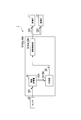
- FIG. 2 is a diagram showing an example of a functional configuration of the control device 10. As shown in FIG.
- the control device 10 includes an information acquisition unit 11, a determination unit 12, and an irradiation control unit 13.
- the sensor SS outputs, to the information acquisition unit 11, a detection signal SS1 indicating the position of the detected object OBJ with respect to the vehicle 1, the distance with respect to the vehicle 1, the angle with respect to the vehicle 1, and the like.
- the information acquisition unit 11 receives the detection signal SS1 from the sensor SS. In addition, the information acquisition unit 11 receives vehicle travel information from the vehicle 1. The information acquisition unit 11 outputs, to the determination unit 12, the detection signal SS1 acquired from the sensor SS and the host vehicle travel information acquired from the vehicle 1.
- the determination unit 12 determines whether or not the object OBJ detected by the sensor SS collides with the vehicle 1.
- the determination unit 12 receives the detection signal SS1 and the host vehicle travel information from the information acquisition unit 11.
- the determination unit 12 determines whether or not the vehicle 1 and the object OBJ collide, based on the detection signal SS1 acquired from the information acquisition unit 11 and the host vehicle travel information.
- a method of determining whether or not the vehicle 1 and the object OBJ collide with each other is arbitrary, and for example, a known technique may be used.
- the determination unit 12 determines that the vehicle 1 and the object OBJ collide with each other, the determination unit 12 controls the irradiation control unit 13 with an irradiation control signal DS for controlling the range of irradiation of the background light and the marking light with respect to the object OBJ. Output.
- the irradiation control unit 13 receives the irradiation control signal DS from the determination unit 12.
- the irradiation control unit 13 performs irradiation control of the headlamp L1 and the headlamp L2 based on the irradiation control signal DS acquired from the determination unit 12. Specifically, the irradiation control unit 13 outputs a headlight control signal CS1 to the headlight L1.
- the headlight L1 emits background light and marking light based on the headlight control signal CS1 input from the irradiation control unit 13.
- the irradiation control unit 13 also outputs a headlamp control signal CS2 to the headlamp L2.
- the headlight L2 irradiates the luminous intensity of the light to be irradiated and the marking light based on the headlight control signal CS2 acquired from the irradiation control unit 13.
- the headlamp control signal CS1 and the headlamp control signal CS2 are not distinguished from one another, they may be collectively referred to as the headlamp control signal CS.
- FIG. 3 is a view showing an example when the headlight L irradiates the background light and the marking light to the object OBJ at a position at which a predetermined distance from the vehicle 1 is apart.
- the headlight L irradiates the background light to the background light irradiation area BGA.
- the headlamp L emits marking light to the object OBJ.
- the area irradiated with the marking light is also described as a marking light irradiation area MLA.
- FIG. 4 is a diagram showing an example of control of the light intensity of background light and the light intensity of marking light.
- a waveform MLW illustrated in FIG. 4 is a waveform indicating the light intensity of the marking light controlled by the irradiation control unit 13.
- a waveform BGW illustrated in FIG. 4 is a waveform indicating the light intensity of the background light controlled by the control device 10.
- time t1 to time t2, time t2 to time t3, time t3 to time t4, and time t4 to time t5 shown in FIG. 4 are respectively the same time intervals.
- the respective luminous intensities from the luminous intensity CD1 to the luminous intensity CD4 shown in FIG. 4 are the brightness on the object OBJ side.
- the luminous intensity CD1 is a predetermined luminous intensity.
- the light intensity CD1 is, for example, 1 lux of brightness.
- the luminous intensity CD3 is the luminous intensity for irradiating the background light irradiation area BGA when the marking light is not irradiated.
- the luminous intensity CD2 is the luminous intensity of the marking light irradiated to the position of the object OBJ.
- This luminous intensity CD2 is lower than the predetermined luminous intensity CD1 of the marking light and higher than the luminous intensity CD3.
- the luminous intensity CD4 of the background light is lower than the luminous intensity CD3 of the background light when the marking light is not irradiated to the object OBJ.
- the difference DCD between the luminous intensity CD2 of the marking light and the CD4 of the background light is a difference for maintaining the contrast sufficient for the driver to visually recognize the object OBJ from the background.
- the irradiation control unit 13 controls the background light and the marking light irradiated from the headlight L so that the brightness does not exceed the light intensity CD1. For example, the irradiation control unit 13 performs control to repeat the lighting and extinguishing of the marking light in a predetermined cycle at such a brightness that the light intensity does not exceed the light intensity CD1. The irradiation control unit 13 reduces the light intensity of the background light to the light intensity CD4 while the marking light is emitted. Specifically, the determination unit 12 determines that the vehicle 1 and the object OBJ collide at time t0. At this time, the headlight L emits background light with the brightness of the light intensity CD3.
- the irradiation control unit 13 irradiates the marking light irradiation area MLA with the marking light of the light intensity CD2 for example, from time t1 to time t2. Further, the irradiation control unit 13 irradiates the background light of the luminous intensity CD4 to the background light irradiation area BGA between time t1 and time t2.
- the control device 10 raises the light intensity of the background light to the light intensity CD3 between time t2 and time t3 when the marking light is not irradiated to the marking light irradiation area MLA.
- the irradiation control unit 13 repeatedly turns on and off the marking light until the determination unit 12 determines that the vehicle 1 and the object OBJ do not collide.
- the irradiation control unit 13 reduces the light intensity of the background light to the light intensity CD4 in accordance with the lighting of the marking light.
- the irradiation control unit 13 returns the luminous intensity of the background light to the original luminous intensity CD3 in accordance with the turning off of the marking light.
- FIG. 5 is a flowchart showing an example of the operation procedure of the control device 10.
- the sensor SS detects an object OBJ (step S10).
- the sensor SS outputs the detection signal SS1 to the information acquisition unit 11.
- the information acquisition unit 11 receives the detection signal SS1 from the sensor SS.
- the information acquisition unit 11 outputs the detection signal SS1 acquired from the sensor SS to the determination unit 12.
- the determination unit 12 receives the detection signal SS1 from the information acquisition unit 11.
- the determination unit 12 determines whether or not the vehicle 1 and the object OBJ collide with each other based on the detection signal SS1 acquired from the information acquisition unit 11 (step S20).
- step S20 If the determination unit 12 determines that the vehicle 1 and the object OBJ do not collide with each other, the process ends (step S20; NO).
- the determination unit 12 determines the area of the object OBJ (step S30).
- the determination unit 12 outputs, to the irradiation control unit 13, an irradiation control signal DS indicating an area on which the marking light is irradiated to the area of the determined object OBJ.
- the irradiation control unit 13 receives the irradiation control signal DS from the determination unit 12.
- the irradiation control unit 13 outputs a headlight control signal CS to the headlight L based on the irradiation control signal DS acquired from the determination unit 12.
- the headlight control signal CS is input to the headlight L from the irradiation control unit 13.
- the headlight L irradiates the object OBJ with the marking light based on the headlight control signal CS input from the irradiation control unit 13 (step S40).
- the irradiation control unit 13 irradiates the marking light to the marking light irradiation area MLA, which is an area corresponding to the object OBJ, and the background light irradiation area, which is an area around the area corresponding to the object OBJ.
- Determination unit 12 determines whether or not object OBJ is still in front of vehicle 1 (step S50).
- step S50 If the determining unit 12 determines that the object OBJ is still present in front of the vehicle 1 (step S50; YES), the process returns to step S30 again.
- step S50 If the determination unit 12 determines that there is no object OBJ in front of the vehicle 1 (step S50; NO), the irradiation of the marking light ends (step S60).
- the control device 10 includes the irradiation control unit 13 so that the luminous intensity of the background light during irradiation of the marking light and the luminous intensity of the background light during the irradiation of the marking light are different from each other. Control. There is a difference between the luminous intensity of the marking light and the luminous intensity of the background light during the irradiation of the marking light to maintain sufficient contrast for the driver driving the vehicle 1 to visually recognize the object OBJ from the background. Thereby, the driver who drives the vehicle 1 does not lose the visibility of the object OBJ. That is, the control device 10 can provide a control device of the headlight of the vehicle that does not impair the driver's notice of the presence of the object OBJ.
- the marking light emits light by blinking on and off repeatedly for the object OBJ, it is easy to direct the driver's attention to the object OBJ. Therefore, the driver's notice can be improved.
- the present invention is not limited to this.
- the light intensity when the light is off may not be zero.
- the irradiation control unit 13 may switch the brightness to a light intensity that allows the driver to recognize the object OBJ, and irradiate the marking light.
- the luminous intensity on the object OBJ side when the marking light is irradiated is a constant luminous intensity CD2
- the luminous intensity on the object OBJ side when the marking light is irradiated is constant It does not have to be CD2.
- the object OBJ in the present embodiment is a pedestrian.
- the glare level is a light intensity at a level causing glare (glare) to the pedestrian irradiated with the marking light.
- the irradiation control unit 13 irradiates the pedestrian (object OBJ) with the marking light having a light intensity lower than the glare level.
- the marking light emitted from the conventional vehicle light of high intensity may be used.
- the high intensity marking light is emitted to a pedestrian (object OBJ)
- the pedestrian may have glare.
- the control device 10 according to the second embodiment does not give glare to the pedestrian (object OBJ) by irradiating the pedestrian (object OBJ) with marking light having a light intensity lower than the glare level, and It is possible to provide a control device for the headlight of a vehicle that does not impair the driver's notice of the presence of this object OBJ.
- control device 10a according to the third embodiment changes the maximum value of the luminous intensity level of the marking light according to the distance between the vehicle 1 and the object OBJ.
- the same configuration and operation as those of the first embodiment and the second embodiment are denoted by the same reference numerals, and the description thereof will be omitted.
- the control device 10a includes an irradiation control unit 13a.
- the irradiation control unit 13a further controls, based on the distance between the object OBJ and the vehicle 1, the luminous intensity of each of the background light irradiation area BGA controlled by the irradiation control unit 13 and the marking light irradiation area MLA.
- the irradiation control unit 13a increases the maximum value of the luminous intensity level of the marking light when the distance between the vehicle 1 and the object OBJ determined to collide with the vehicle 1 by the determination unit 12 increases. Specifically, the irradiation control unit 13a moves the object OBJ while emitting marking light to the object OBJ, for example, as shown in FIG. 6 when the distance between the vehicle 1 and the object OBJ increases. As shown, increase the maximum light intensity level of the marking light.
- the maximum value of the luminous intensity level of this marking light is larger than, for example, the luminous intensity CD1 shown in FIG. 4 and FIG.
- the difference between the maximum value of the luminous intensity of the marking light and the luminous intensity CD3 of the background light is a difference DCD which allows the driver to maintain a sufficient contrast for visualizing the object OBJ from the background.
- the irradiation control unit 13a makes the maximum value of the light intensity level of the marking light smaller than the light intensity CD1. Do. Specifically, the irradiation control unit 13a moves the object OBJ while emitting marking light to the object OBJ, for example, as shown in FIG. 4 when the distance between the vehicle 1 and the object OBJ decreases. As shown, reduce the maximum intensity level of the marking light. At this time, the difference between the reduced luminosity of the marking light and the luminosity CD3 of the background light is a difference DCD which allows the driver to maintain a sufficient contrast for visualizing the object OBJ from the background.
- the control apparatus 10a which concerns on 3rd Embodiment is provided with the irradiation control part 13a.
- the irradiation control unit 13a increases the maximum value of the luminous intensity level of the marking light when the distance between the vehicle 1 and the object OBJ determined to collide with the vehicle 1 increases.
- the control device 10a can irradiate the object OBJ at a position farther than the predetermined distance with the marking light having the same brightness as the object OBJ located at the predetermined distance. . Thereby, the driver who drives the vehicle 1 does not lose visibility even if it is the object OBJ located at a position farther than the predetermined distance.
- a control device 10b according to the fourth embodiment When the object OBJ is a pedestrian, the control device 10b according to the fourth embodiment detects the direction of the face of the pedestrian and changes the maximum value of the luminous intensity level of the marking light.
- the same configuration and operation as those of the second embodiment and the third embodiment are denoted by the same reference numerals, and the description thereof will be omitted.
- the control device 10 b includes a determination unit 12 b and an irradiation control unit 13 b.
- the determination unit 12b determines the direction of the face of the pedestrian (object OBJ). For example, the determination unit 12b determines the direction of the face of the pedestrian by detecting the pupil of the pedestrian (object OBJ). Specifically, the determination unit 12b determines that the object OBJ is a pedestrian (person), and detects the position of the pupil of the pedestrian. If the pupil of the pedestrian can not be detected, the determination unit 12 b determines that the direction of the face of the pedestrian does not face the direction of the headlight L of the vehicle 1.
- the determination unit 12 b detects the pupil of the pedestrian, the orientation of the pedestrian's face is determined to be directed to the direction of the headlight L of the vehicle 1.
- the determination unit 12b outputs, to the irradiation control unit 13b, direction information indicating the determined direction of the face of the pedestrian.
- the irradiation control unit 13 b controls the luminous intensity of the marking light based on the direction information input from the determination unit 12 b. For example, when the direction information indicates that the pedestrian (the object OBJ) faces the direction of the headlight L of the vehicle 1, the irradiation control unit 13b may set the second light intensity of the marking light. Control to the light intensity shown in the embodiment. When the direction information indicates that the pedestrian (object OBJ) does not point in the direction of the headlight L of the vehicle 1, the irradiation control unit 13b determines the light intensity of the marking light and the light intensity of the background light, The light intensity is controlled as shown in FIG.
- FIG. 6 is a diagram showing an example of control of the light intensity of background light and the light intensity of marking light according to the fourth embodiment.
- a waveform MLW2 illustrated in FIG. 6 is a waveform indicating the light intensity of the marking light controlled by the irradiation control unit 13b.
- the waveform BGW2 shown in FIG. 6 is a waveform indicating the light intensity of the background light controlled by the control device 10b.
- the light intensity CD5 shown in FIG. 6 is larger than the light intensity CD1 (glare level).
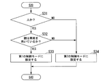
- FIG. 7 is a flow chart showing an example of the operation procedure of the control device 10b.
- control device 10b differs in the operation procedure of step S30.
- the determination unit 12b determines whether the object OBJ detected by the sensor SS is a person (step S31). If it is determined that the object OBJ is not a person in step S31 described above (step S31; NO), the determination unit 12b sets the irradiation control unit 13b in the second control mode (step S34).
- the second control mode is a mode in which the marking light is irradiated by increasing the maximum value of the luminous intensity level of the marking light shown in FIG.
- Step S31 If it is determined that the object OBJ is a person (YES), the determination unit 12b determines whether the face of the person detected by the sensor SS is directed to the vehicle 1 (Step S32). . When determining that the face of the person detected by the sensor SS does not face the direction of the vehicle 1 (step S32; NO), the determining unit 12b sets the irradiation control unit 13b in the second control mode. (Step S34).
- the determination unit 12b sets the irradiation control unit 13b to the first control mode (step S12).
- the first control mode is a mode in which the marking light of the light intensity not exceeding the glare level is irradiated as shown in FIG. 4 described in the second embodiment.
- the control device 10b includes the determination unit 12b and the irradiation control unit 13b.
- the determination unit 12b determines the direction of the face of the pedestrian (object OBJ).
- the irradiation control unit 13b changes the maximum value of the luminous intensity of the marking light based on the determination result of the determination unit 12b. By configuring in this manner, the control device 10b can provide irradiation control of the marking light without giving glare to the pedestrian and not losing the driver's notice of the presence of the pedestrian.
- the lamp that emits the marking light in the first embodiment, the second embodiment, the third embodiment, and the fourth embodiment described above includes, for example, a MEMS (Micro Electro-Mechanical Systems) laser scanning head.
- a lamp, a DMD (Digital Micromirror Device) headlamp, a matrix ADB (Adaptive Driving Beam) headlamp, an ADB (Adaptive Driving Beam) headlamp or the like can be used.
- the lamps for irradiating the background light in the first embodiment, the second embodiment, the third embodiment and the fourth embodiment described above include, for example, a MEMS laser scanning head lamp, a DMD head lamp, and a matrix.
- ADB headlamps, ADB headlamps and the like can be used.
- the control apparatus 10 demonstrated the structure to which own vehicle travel information is input from the vehicle 1 in the description mentioned above, it is not restricted to this.
- the control device 10 includes, for example, a speed sensor that detects information on the speed of the vehicle, a gyro sensor that detects information on the attitude of the vehicle, a steering angle sensor that detects information on the steering angle of the vehicle, and acceleration of the vehicle.
- a speed sensor that detects information on the speed of the vehicle
- a gyro sensor that detects information on the attitude of the vehicle
- a steering angle sensor that detects information on the steering angle of the vehicle
- acceleration of the vehicle One or more of an acceleration sensor that detects information and a position sensor that detects information of the position of the vehicle may be provided.
- the position sensor which has a function of GPS (Global Positioning System) may be used, for example.
- vehicle 1 is a motor vehicle
- vehicle 1 may be another type of vehicle such as a motorcycle.
- ramp which irradiates the marking light mentioned above may be a lamp
- the irradiation control unit 13 irradiates the marking light to the object OBJ located on the front left side of the vehicle 1 by controlling the headlamp L1, for example. Further, the irradiation control unit 13 controls the headlamp L2 to irradiate the marking light to the object OBJ located on the front right side of the vehicle 1.
- the irradiation control unit 13 may irradiate the marking light to the object OBJ located in front of the front of the vehicle 1 using any of the headlights L1 and L2.
- the control device 10, the control device 10a and the control device 10b described above have a computer inside.
- the process of each process of the apparatus described above is stored in a computer readable recording medium in the form of a program, and the above process is performed by the computer reading and executing this program.
- the computer-readable recording medium refers to a magnetic disk, a magneto-optical disk, a CD-ROM, a DVD-ROM, a semiconductor memory and the like.
- the computer program may be distributed to a computer through a communication line, and the computer that has received the distribution may execute the program.
- the program may be for realizing a part of the functions described above. Furthermore, it may be a so-called difference file (difference program) that can realize the above-described functions in combination with a program already recorded in the computer system.
- difference file difference program
- SYMBOLS 1 Vehicle, 10, 10a, 10b ... Control apparatus, 11 ... Information acquisition part, 12, 12b ... Determination part, 13, 13a, 13b ... Irradiation control part, SS ... Sensor, L1, L2 ... Headlight, BGA ... Background light irradiation area, OBJ ... Object, MLA ... Marking light irradiation area
Landscapes
- Engineering & Computer Science (AREA)
- Mechanical Engineering (AREA)
- Lighting Device Outwards From Vehicle And Optical Signal (AREA)
Abstract
Dispositif de commande pour phares de véhicule qui commande l'éclairage par les phares d'un véhicule, comprenant : une partie de détermination pour déterminer si un objet détecté par une partie de détection d'objet destinée à détecter des objets entrera ou non en collision avec le véhicule ; et une partie de commande d'éclairage qui amène les phares à éclairer, à l'aide d'une lumière de marquage, une région correspondant à l'objet qui entrera en collision avec le véhicule en fonction de la détermination par la partie de détermination et éclairer, à l'aide d'une lumière de fond, une région autour de ladite région correspondant à l'objet, la lumière de fond ayant une intensité lumineuse qui diminue lorsque l'intensité de la lumière de marquage augmente.
Priority Applications (1)
| Application Number | Priority Date | Filing Date | Title |
|---|---|---|---|
| US16/643,762 US11077787B2 (en) | 2017-09-08 | 2018-09-07 | Control device for vehicle headlamps |
Applications Claiming Priority (2)
| Application Number | Priority Date | Filing Date | Title |
|---|---|---|---|
| JP2017173143A JP7000084B2 (ja) | 2017-09-08 | 2017-09-08 | 車両の前照灯の制御装置 |
| JP2017-173143 | 2017-09-08 |
Publications (1)
| Publication Number | Publication Date |
|---|---|
| WO2019049986A1 true WO2019049986A1 (fr) | 2019-03-14 |
Family
ID=65634998
Family Applications (1)
| Application Number | Title | Priority Date | Filing Date |
|---|---|---|---|
| PCT/JP2018/033199 Ceased WO2019049986A1 (fr) | 2017-09-08 | 2018-09-07 | Dispositif de commande pour phares de véhicule |
Country Status (3)
| Country | Link |
|---|---|
| US (1) | US11077787B2 (fr) |
| JP (1) | JP7000084B2 (fr) |
| WO (1) | WO2019049986A1 (fr) |
Families Citing this family (4)
| Publication number | Priority date | Publication date | Assignee | Title |
|---|---|---|---|---|
| KR102245384B1 (ko) | 2019-09-30 | 2021-04-28 | 현대모비스 주식회사 | 차량용 헤드램프의 빔패턴 제어장치 및 그 방법 |
| WO2022050307A1 (fr) * | 2020-09-04 | 2022-03-10 | 株式会社小糸製作所 | Lampe d'avertissement et lampe d'avertissement de véhicule |
| JP2024132428A (ja) * | 2023-03-17 | 2024-10-01 | 本田技研工業株式会社 | 車両用照明装置及び照明装置 |
| JP7688085B2 (ja) * | 2023-09-29 | 2025-06-03 | 本田技研工業株式会社 | 車両用照明装置、車両用照明制御方法、およびプログラム |
Citations (3)
| Publication number | Priority date | Publication date | Assignee | Title |
|---|---|---|---|---|
| WO2014024385A1 (fr) * | 2012-08-08 | 2014-02-13 | 株式会社小糸製作所 | Luminaire pour véhicule |
| JP2014184851A (ja) * | 2013-03-22 | 2014-10-02 | Toyota Central R&D Labs Inc | 照射装置 |
| JP2017061206A (ja) * | 2015-09-24 | 2017-03-30 | スタンレー電気株式会社 | 車両用前照灯システム |
Family Cites Families (5)
| Publication number | Priority date | Publication date | Assignee | Title |
|---|---|---|---|---|
| JP5003398B2 (ja) | 2007-10-10 | 2012-08-15 | 株式会社豊田中央研究所 | 照明装置 |
| JP5959822B2 (ja) | 2011-10-06 | 2016-08-02 | 株式会社小糸製作所 | 車両用スポットランプ制御装置および車両用スポットランプシステム |
| JP5992278B2 (ja) | 2012-09-20 | 2016-09-14 | スタンレー電気株式会社 | 車両用前照灯の点灯制御装置、車両用前照灯システム |
| US20150329043A1 (en) * | 2014-05-13 | 2015-11-19 | Continental Automotive Systems, Inc. | Warning to a Pedestrian in Dangerous Situation |
| US9771021B1 (en) * | 2016-05-03 | 2017-09-26 | Toyota Motor Engineering & Manufacturing North America, Inc. | Pedestrian marking systems |
-
2017
- 2017-09-08 JP JP2017173143A patent/JP7000084B2/ja active Active
-
2018
- 2018-09-07 US US16/643,762 patent/US11077787B2/en active Active
- 2018-09-07 WO PCT/JP2018/033199 patent/WO2019049986A1/fr not_active Ceased
Patent Citations (3)
| Publication number | Priority date | Publication date | Assignee | Title |
|---|---|---|---|---|
| WO2014024385A1 (fr) * | 2012-08-08 | 2014-02-13 | 株式会社小糸製作所 | Luminaire pour véhicule |
| JP2014184851A (ja) * | 2013-03-22 | 2014-10-02 | Toyota Central R&D Labs Inc | 照射装置 |
| JP2017061206A (ja) * | 2015-09-24 | 2017-03-30 | スタンレー電気株式会社 | 車両用前照灯システム |
Also Published As
| Publication number | Publication date |
|---|---|
| US11077787B2 (en) | 2021-08-03 |
| US20200223351A1 (en) | 2020-07-16 |
| JP2019048526A (ja) | 2019-03-28 |
| JP7000084B2 (ja) | 2022-01-19 |
Similar Documents
| Publication | Publication Date | Title |
|---|---|---|
| CN103249597B (zh) | 车辆配光控制装置以及方法 | |
| JP6545983B2 (ja) | 車両灯具システム | |
| JP6350402B2 (ja) | 車両用前照灯制御装置 | |
| EP1970249A2 (fr) | Procédé et système d'aide à la conduite de véhicule | |
| JP6319204B2 (ja) | 車両用の前照灯制御装置 | |
| JP2015033944A (ja) | 車両用前照灯の点灯制御装置、車両用前照灯システム | |
| JP6723290B2 (ja) | 車両用ヘッドランプシステムおよびその制御方法 | |
| JP7273839B2 (ja) | 灯具システム | |
| CN105939892A (zh) | 前照灯控制装置及前照灯 | |
| WO2019049986A1 (fr) | Dispositif de commande pour phares de véhicule | |
| JP7312913B2 (ja) | 自動車両の照明システムを制御するための方法 | |
| JP2016181351A (ja) | 車両用前照灯 | |
| CN114867639B (zh) | 用于控制机动车辆照明系统的方法 | |
| US20190077304A1 (en) | Control device for vehicle headlight | |
| JP2014058173A (ja) | 車両用前照灯の点灯制御装置、車両用前照灯システム | |
| JP6296734B2 (ja) | 車両用前照灯の点灯制御装置、車両用前照灯システム | |
| JP7137414B2 (ja) | 車両用灯具 | |
| JP2013079043A (ja) | 車両用前照灯の点灯制御装置、車両用前照灯システム | |
| JP5808611B2 (ja) | 車両用前照灯の点灯制御装置、車両用前照灯システム | |
| JP2013043617A (ja) | 車両用前照灯の点灯制御装置、車両用前照灯システム | |
| WO2016021154A1 (fr) | Dispositif d'éclairage, et automobile dans laquelle il est monté | |
| JP2014040177A (ja) | 車両用前照灯の点灯制御装置、車両用前照灯システム | |
| JP6162012B2 (ja) | 車両用前照灯の点灯制御装置、車両用前照灯システム | |
| JP2019137324A (ja) | 車両用灯具の点灯制御装置、車両用灯具の点灯制御方法、車両用灯具システム | |
| WO2018146801A1 (fr) | Procédé et appareil de commande d'éclairage de véhicule |
Legal Events
| Date | Code | Title | Description |
|---|---|---|---|
| 121 | Ep: the epo has been informed by wipo that ep was designated in this application |
Ref document number: 18853047 Country of ref document: EP Kind code of ref document: A1 |
|
| NENP | Non-entry into the national phase |
Ref country code: DE |
|
| 122 | Ep: pct application non-entry in european phase |
Ref document number: 18853047 Country of ref document: EP Kind code of ref document: A1 |