WO2019053886A1 - Aimant permanent, machine électrique rotative et véhicule - Google Patents
Aimant permanent, machine électrique rotative et véhicule Download PDFInfo
- Publication number
- WO2019053886A1 WO2019053886A1 PCT/JP2017/033494 JP2017033494W WO2019053886A1 WO 2019053886 A1 WO2019053886 A1 WO 2019053886A1 JP 2017033494 W JP2017033494 W JP 2017033494W WO 2019053886 A1 WO2019053886 A1 WO 2019053886A1
- Authority
- WO
- WIPO (PCT)
- Prior art keywords
- permanent magnet
- crystal phase
- atomic
- phase
- less
- Prior art date
- Legal status (The legal status is an assumption and is not a legal conclusion. Google has not performed a legal analysis and makes no representation as to the accuracy of the status listed.)
- Ceased
Links
Images



Classifications
-
- H—ELECTRICITY
- H01—ELECTRIC ELEMENTS
- H01F—MAGNETS; INDUCTANCES; TRANSFORMERS; SELECTION OF MATERIALS FOR THEIR MAGNETIC PROPERTIES
- H01F1/00—Magnets or magnetic bodies characterised by the magnetic materials therefor; Selection of materials for their magnetic properties
- H01F1/01—Magnets or magnetic bodies characterised by the magnetic materials therefor; Selection of materials for their magnetic properties of inorganic materials
- H01F1/03—Magnets or magnetic bodies characterised by the magnetic materials therefor; Selection of materials for their magnetic properties of inorganic materials characterised by their coercivity
- H01F1/032—Magnets or magnetic bodies characterised by the magnetic materials therefor; Selection of materials for their magnetic properties of inorganic materials characterised by their coercivity of hard-magnetic materials
- H01F1/04—Magnets or magnetic bodies characterised by the magnetic materials therefor; Selection of materials for their magnetic properties of inorganic materials characterised by their coercivity of hard-magnetic materials metals or alloys
- H01F1/047—Alloys characterised by their composition
- H01F1/053—Alloys characterised by their composition containing rare earth metals
- H01F1/055—Alloys characterised by their composition containing rare earth metals and magnetic transition metals, e.g. SmCo5
- H01F1/0555—Alloys characterised by their composition containing rare earth metals and magnetic transition metals, e.g. SmCo5 pressed, sintered or bonded together
- H01F1/0557—Alloys characterised by their composition containing rare earth metals and magnetic transition metals, e.g. SmCo5 pressed, sintered or bonded together sintered
-
- B—PERFORMING OPERATIONS; TRANSPORTING
- B22—CASTING; POWDER METALLURGY
- B22F—WORKING METALLIC POWDER; MANUFACTURE OF ARTICLES FROM METALLIC POWDER; MAKING METALLIC POWDER; APPARATUS OR DEVICES SPECIALLY ADAPTED FOR METALLIC POWDER
- B22F3/00—Manufacture of workpieces or articles from metallic powder characterised by the manner of compacting or sintering; Apparatus specially adapted therefor ; Presses and furnaces
- B22F3/24—After-treatment of workpieces or articles
-
- B—PERFORMING OPERATIONS; TRANSPORTING
- B22—CASTING; POWDER METALLURGY
- B22F—WORKING METALLIC POWDER; MANUFACTURE OF ARTICLES FROM METALLIC POWDER; MAKING METALLIC POWDER; APPARATUS OR DEVICES SPECIALLY ADAPTED FOR METALLIC POWDER
- B22F3/00—Manufacture of workpieces or articles from metallic powder characterised by the manner of compacting or sintering; Apparatus specially adapted therefor ; Presses and furnaces
- B22F3/24—After-treatment of workpieces or articles
- B22F2003/248—Thermal after-treatment
-
- B—PERFORMING OPERATIONS; TRANSPORTING
- B22—CASTING; POWDER METALLURGY
- B22F—WORKING METALLIC POWDER; MANUFACTURE OF ARTICLES FROM METALLIC POWDER; MAKING METALLIC POWDER; APPARATUS OR DEVICES SPECIALLY ADAPTED FOR METALLIC POWDER
- B22F2998/00—Supplementary information concerning processes or compositions relating to powder metallurgy
- B22F2998/10—Processes characterised by the sequence of their steps
-
- B—PERFORMING OPERATIONS; TRANSPORTING
- B22—CASTING; POWDER METALLURGY
- B22F—WORKING METALLIC POWDER; MANUFACTURE OF ARTICLES FROM METALLIC POWDER; MAKING METALLIC POWDER; APPARATUS OR DEVICES SPECIALLY ADAPTED FOR METALLIC POWDER
- B22F2999/00—Aspects linked to processes or compositions used in powder metallurgy
-
- C—CHEMISTRY; METALLURGY
- C22—METALLURGY; FERROUS OR NON-FERROUS ALLOYS; TREATMENT OF ALLOYS OR NON-FERROUS METALS
- C22C—ALLOYS
- C22C19/00—Alloys based on nickel or cobalt
- C22C19/07—Alloys based on nickel or cobalt based on cobalt
-
- C—CHEMISTRY; METALLURGY
- C22—METALLURGY; FERROUS OR NON-FERROUS ALLOYS; TREATMENT OF ALLOYS OR NON-FERROUS METALS
- C22C—ALLOYS
- C22C38/00—Ferrous alloys, e.g. steel alloys
- C22C38/005—Ferrous alloys, e.g. steel alloys containing rare earths, i.e. Sc, Y, Lanthanides
-
- C—CHEMISTRY; METALLURGY
- C22—METALLURGY; FERROUS OR NON-FERROUS ALLOYS; TREATMENT OF ALLOYS OR NON-FERROUS METALS
- C22C—ALLOYS
- C22C38/00—Ferrous alloys, e.g. steel alloys
- C22C38/10—Ferrous alloys, e.g. steel alloys containing cobalt
-
- C—CHEMISTRY; METALLURGY
- C22—METALLURGY; FERROUS OR NON-FERROUS ALLOYS; TREATMENT OF ALLOYS OR NON-FERROUS METALS
- C22C—ALLOYS
- C22C38/00—Ferrous alloys, e.g. steel alloys
- C22C38/14—Ferrous alloys, e.g. steel alloys containing titanium or zirconium
-
- C—CHEMISTRY; METALLURGY
- C22—METALLURGY; FERROUS OR NON-FERROUS ALLOYS; TREATMENT OF ALLOYS OR NON-FERROUS METALS
- C22C—ALLOYS
- C22C38/00—Ferrous alloys, e.g. steel alloys
- C22C38/16—Ferrous alloys, e.g. steel alloys containing copper
-
- H—ELECTRICITY
- H01—ELECTRIC ELEMENTS
- H01F—MAGNETS; INDUCTANCES; TRANSFORMERS; SELECTION OF MATERIALS FOR THEIR MAGNETIC PROPERTIES
- H01F41/00—Apparatus or processes specially adapted for manufacturing or assembling magnets, inductances or transformers; Apparatus or processes specially adapted for manufacturing materials characterised by their magnetic properties
- H01F41/02—Apparatus or processes specially adapted for manufacturing or assembling magnets, inductances or transformers; Apparatus or processes specially adapted for manufacturing materials characterised by their magnetic properties for manufacturing cores, coils, or magnets
- H01F41/0253—Apparatus or processes specially adapted for manufacturing or assembling magnets, inductances or transformers; Apparatus or processes specially adapted for manufacturing materials characterised by their magnetic properties for manufacturing cores, coils, or magnets for manufacturing permanent magnets
- H01F41/0266—Moulding; Pressing
Definitions
- Embodiments relate to a permanent magnet, a rotating electrical machine, and a vehicle.
- rare earth magnets such as Sm-Co based magnets and Nd-Fe-B based magnets are known. These magnets currently mass-produced contain a large amount of Fe and Co. Fe and Co contribute to the increase in saturation magnetization. In addition, rare earth elements such as Sm and Nd are also essential. These magnets are derived from the behavior of 4f electrons of rare earth elements and have large magnetic anisotropy. For these reasons, the rare earth magnet is a strong magnet having both high magnetization and high coercivity. Therefore, it is used for various motors etc. for which size reduction and high efficiency are required.
- Factors that determine the performance of the variable magnet include residual magnetization, coercivity, and squareness.
- residual magnetization By increasing the residual magnetization, the maximum value of the magnetic flux is increased.
- the coercivity needs to be controlled within the range of about 100 to 500 kA / m to an optimum value derived from the design of a motor or the like. This is to make it easy to increase or decrease the magnetic flux of the variable magnet by the external magnetic field.
- high squareness is required to maintain the change width of the magnetic flux.
- a Sm-Co based magnet is suitable for the variable magnet.
- the reason is due to the pinning type coercive force mechanism of the Sm—Co based magnet. This is because a region with small magnetization change can be widely obtained in the minor loop of the magnetic property, and the flux variable width can be broadened.
- the problem to be solved by the present invention is to improve the residual magnetization while controlling the coercivity of the permanent magnet to a value suitable for the variable magnet.
- the permanent magnet of the embodiment is represented by a composition formula: R p Fe q M r Cu s Co 100-p-q-r-s .
- Permanent magnet comprises crystal grains having a major phase comprising the TbCu 7 crystal phase, the volume ratio of the TbCu 7 crystal phase of the main phase of the constituent phases is 95% or more.
- the permanent magnet of the embodiment is represented by the following composition formula.
- R p Fe q M r Cu s Co 100-p-q-r-s (Wherein, R is at least one element selected from the group consisting of rare earth elements, M is at least one element selected from the group consisting of Zr, Ti and Hf, p, q, r and s are each At atomic%, 10.5 ⁇ p ⁇ 12.5, 25 ⁇ q ⁇ 40, 0.88 ⁇ r ⁇ 4.5, 3.5 ⁇ s ⁇ 10.7)
- the R element brings a large magnetic anisotropy to the permanent magnet and imparts high coercivity.
- R element one or more rare earth elements are used.
- the R element it is more preferable to use at least one element selected from the group consisting of yttrium (Y), samarium (Sm), cerium (Ce), neodymium (Nd), and praseodymium (Pr), for example. It is preferable to use By setting at least 50 atomic% of the R element to Sm, the performance of the permanent magnet, in particular, the coercivity can be reproducibly enhanced. Furthermore, it is more preferable that 70 atomic% or more, further 90 atomic% or more of R element is Sm.
- the content of the R element is, for example, 10.5 at% or more and 12.5 at% or less.
- the content of the R element is more preferably 10.9 atomic% to 12.0 atomic%, and further preferably 11.0 atomic% to 11.6 atomic%.
- the M element at least one element selected from the group consisting of titanium (Ti), zirconium (Zr), and hafnium (Hf) is used.
- the coercivity can be expressed with a composition of high Fe concentration.
- the content of the element M is 0.88 at% or more and 4.5 at% or less. When the content of M element is less than 0.88 atomic%, the effect of increasing the Fe concentration is small, and when it exceeds 4.5 atomic%, a phase containing an excessive amount of M element is generated, and the magnetic characteristics are easily deteriorated.
- the content of the element M is more preferably 1.14 atomic percent or more and 3.58 atomic percent or less, and further preferably 1.55 atomic percent or more and 2.23 atomic percent or less.
- the M element may be any of Ti, Zr and Hf, but preferably contains at least Zr.
- the effect of enhancing the coercive force of the permanent magnet can be further improved.
- Hf is particularly expensive, so even when using Hf, it is preferable to reduce its amount used.
- the content of Hf is preferably less than 20 atomic% of the M element.
- Copper (Cu) develops the coercivity of permanent magnets.
- the content of Cu is 3.5 atomic% or more and 10.7 atomic% or less. Since Cu is a nonmagnetic element, the decrease in magnetization is remarkable when it exceeds 10.7 atomic%. If it is less than 3.5 atomic%, it will be difficult to obtain high coercivity.
- the content of Cu is 3.9 atomic percent or more and 9.0 atomic percent or less, further 4.3 atomic percent or more and 6.0 atomic percent or less, and further 5.0 atomic percent or more and 5.6 atomic percent or less Is preferred.
- Iron (Fe) is mainly responsible for the magnetization of permanent magnets. By including a large amount of Fe, the saturation magnetization of the permanent magnet can be increased. However, if the content of Fe is excessive, the coercivity decreases due to the precipitation of the ⁇ -Fe phase and the like.
- the blending amount of Fe is in the range of 25 atomic% to 40 atomic%. The content is more preferably 26 atomic percent or more and 36 atomic percent or less, still more preferably 29 atomic percent or more and 35 atomic percent or less, and still more preferably 30 atomic percent or more and 33 atomic percent or less.
- Co Cobalt
- the content of Co is in the range defined by p, q, r, t (100-p-q-r-t).
- a part of Co is nickel (Ni), vanadium (V), chromium (Cr), manganese (Mn), aluminum (Al), silicon (Si), gallium (Ga), niobium (Nb), tantalum (Ta), And at least one element A selected from the group consisting of tungsten and tungsten (W).
- These substitution elements contribute to the improvement of the magnet characteristics, for example, the coercivity.
- the amount of substitution by the element A is in the range of 20 atomic% or less of Co.
- the composition of the permanent magnet is, for example, high-frequency inductively coupled plasma (ICP) emission spectroscopy, scanning electron microscope-energy dispersive X-ray spectroscopy (SEM-EDX), transmission It is measured by an electron microscope-energy dispersive X-ray spectroscopy (Transmission Electron Microscope-EDX: TEM-EDX) or the like.
- ICP inductively coupled plasma
- SEM-EDX scanning electron microscope-energy dispersive X-ray spectroscopy
- TEM-EDX transmission Electron Microscope-EDX: TEM-EDX
- the permanent magnet includes a sintered body having a two-dimensional metal structure including crystal grains having a main phase and crystal grain boundaries (also referred to as grain boundary phases) of the crystal grains.
- the main phase is defined by the phase having the largest volume ratio of all constituent phases.
- the proportion of the main phase is preferably 70% by volume or more, and more preferably 90% by volume or more in all constituent phases.
- the metal structure is observed using, for example, a scanning electron microscope (SEM).
- the grain boundary phase exists around the crystal grains.
- the melting point of the grain boundary phase is lower than that of the main phase.
- the grain boundary phase includes, for example, a Ce 2 Ni 7 crystal phase (2-7 crystal phase), a CaCu 5 crystal phase (1-5 crystal phase), and the like.
- FIG. 1 is a view showing an example of an X-ray diffraction pattern of a permanent magnet.
- the XRD pattern shown in FIG. 1 has a peak derived from a hexagonal TbCu 7 crystal phase (1-7 crystal phase). That is, the main phase has a TbCu 7 type crystal phase.
- the relative intensity with respect to the largest peak derived from the TbCu 7 type crystal phase of the peak derived from the Th 2 Zn 17 type crystal phase having 2 ⁇ of 37.5 degrees or more and 38.5 degrees or less is 0.4 or less.
- the relative strength of 0.4 or less indicates that the volume fraction of the Th 2 Zn 17 crystal phase is small or absent among the constituent phases of the crystal grains.
- the volume ratio of the 1-7 type crystal phase is 95% or more among the constituent phases of the main phase. That is, the main phase substantially has a single phase structure of a 1-7 type crystal phase.
- the volume ratio of each phase of the metallographic structure can be judged comprehensively by using, for example, observation with an electron microscope or an optical microscope in combination with X-ray diffraction etc.
- an area analysis method of an electron micrograph of a cross section of a permanent magnet It can be determined by As the cross section of the permanent magnet, the cross section of the substantially central portion of the surface having the largest area of the sample is used.
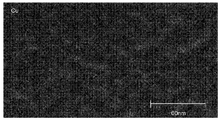
- FIG. 2 is a view showing a Cu mapping image obtained by TEM-EDX analysis of a 1-7 type crystal phase.
- the 1-7 type crystal phase has a concentration of Cu.
- the dispersion of the Cu concentration in the 1-7 type crystal phase is preferably 0.7 or more.
- a Sm 2 Co 17- based magnet (2-17 magnet) is known as a high iron concentration SmCo-based magnet.
- the cell phase consisting of the Th 2 Zn 17 crystal phase and the cell wall phase consisting of the CaCu 5 crystal phase form a cell structure, and the cell wall phase becomes a domain wall pinning site, resulting in coercivity It is expressed.
- the permanent magnet of the embodiment a cell structure causing a coercivity like a 2-17 magnet is not observed.
- the 1-7 type crystal phase has a concentration of Cu. It is considered that the coercivity is expressed by the region where the Cu concentration is concentrated becoming a domain wall pinning site.
- Such a coercivity expression mechanism is called a domain wall pinning type coercivity expression mechanism.
- the permanent magnet of the embodiment exhibits a pinning type initial magnetization curve.
- the magnetization of the CaCu 5- type crystal phase of the cell wall phase is low, the magnetization decreases when the cell structure is formed to express the coercive force.
- the permanent magnet of the embodiment does not have a cell structure, it is possible to maintain high magnetization and express coercivity.
- the residual magnetization can be set to 1, 21 T or more while controlling the coercive force to 100 kA / m or more and 500 kA / m or less.
- the permanent magnet is suitable, for example, for a variable magnet.
- domain wall motion does not occur unless an external field exceeding the pinning potential is added even if a magnetization reversal nucleus serving as a starting point of magnetization reversal is generated. Therefore, the existence form of the pinning site is dominant as a factor determining the magnitude of the coercivity.
- the permanent magnet of the embodiment contains 25 at% or more and 40 at% or less of Fe.
- the coercivity is difficult to express and magnetization reversal nuclei are easily generated, so it is difficult to obtain a good squareness ratio, which is a factor to decrease the (BH) max of the permanent magnet.
- the distribution form of the Cu concentration to be the pinning site is controlled in the range of Fe and Cu concentrations capable of maintaining sufficient magnetization.
- both high magnetization and coercivity necessary for the variable magnet can be realized. That is, it is possible to provide a high-performance variable magnet.
- the Cu concentration distribution is measured as follows.
- the composition of the permanent magnet is analyzed by TEM-EDX. In the TEM, for example, a region of 100 nm ⁇ 100 nm or more and 400 nm ⁇ 400 nm or less is observed at a magnification of 500,000 times.
- the acceleration voltage is preferably 200 kV.
- the composition of the surface and the inside of the cross section perpendicular to the side is taken at the center of the longest side of the plane with the largest area taking measurement.
- the measurement point is the first reference line drawn inward to the end perpendicularly to the side starting from the 1 ⁇ 2 position of each side in the above cross section and the corner portion starting from the center of each corner
- a second reference line drawn inward to the end at a half angle of the inner angle of the reference angle of the reference angle, and the length of the reference line from the start point of the first reference line and the second reference line
- the position of 1% is defined as the surface portion
- the position of 40% is defined as the inside.
- the reference lines become 8 in total of four each at the first reference line and the second reference line, and the measurement points are on the surface and inside There are eight places each.
- the Cu concentration is measured at a plurality of locations in the TEM image.
- the measurement points are measured at the intersections of the two sides of the measurement plane, which are equally divided into the vertical and horizontal sides. The number of divisions of each side is selected so that the number of measurement points is 20 or more.
- the Cu concentration distribution can be measured by calculating the dispersion of the Cu concentration obtained at each point. The variance is calculated, for example, by the following equation.
- S 2 represents the variance of the Cu concentration
- n represents the number of measuring points
- X i represents the Cu concentration of each measurement point
- / X represents the mean value of the Cu concentration of all measuring points.
- all eight locations in the surface portion and in the inside be within the above-described dispersion range, but four or more locations in each of the surface portion and the inside should be within the above-described range. In this case, the relationship between the surface portion and the inside of one reference line is not defined.
- the concentrated region of the Cu concentration is present in the form of a band having a long side of about 10 nm to 100 nm or a spherical shape having a diameter of about 1 to 10 nm.
- the dispersion may be realized by distributing continuous concentrated regions in space.
- an alloy powder containing a predetermined element necessary for synthesizing a permanent magnet is prepared.
- the alloy powder can be prepared by crushing an alloy ingot obtained by casting a molten metal by an arc melting method or a high frequency melting method.
- the alloy powder may be made into a desired composition by mixing a plurality of powders having different compositions.
- Mechanical alloying method, mechanical grinding method, gas atomization method, reduction diffusion method etc. are mentioned as another example of a preparation method of alloy powder.
- the uniformity of the alloy powder can be improved.
- the material can be crushed using a jet mill, a ball mill or the like.
- oxidation of the powder can be prevented by grinding the material in an inert gas atmosphere or an organic solvent.
- the average particle size of the pulverized powder is preferably 2 ⁇ m or more and 8 ⁇ m or less.
- the average particle diameter of the powder after grinding is preferably 3 ⁇ m to 7.5 ⁇ m, more preferably 4 ⁇ m to 7 ⁇ m, and still more preferably 4.5 ⁇ m to 6 ⁇ m.
- the amount of oxides can be suppressed by setting the ratio of particles having a particle diameter of 1 ⁇ m or less to 1 volume% or less. By setting the ratio of particles having a particle diameter of 10 ⁇ m or more to 2 volume% or less, the porosity of the sintered body produced after sintering is reduced, and a sufficient density can be realized.
- the average particle diameter of the powder is defined by the value of the particle diameter (median diameter: d50) at which the cumulative distribution becomes 50% in the particle size distribution measured by a laser diffraction method or the like. It is suitable to use a jet mill for producing such powder.
- the alloy powder is filled in a mold placed in an electromagnet, and pressed while applying a magnetic field to produce a green compact having crystal axes oriented.
- a molding method there are a dry molding method and a wet molding method.
- the dry molding method it is preferable to add a small amount of a lubricant in order to improve the flowability of the powder and to prevent oxidation.
- the lubricant include silicone oil and mineral oil.
- the green compact is sintered by heat treatment at 1180 ° C. or more and 1250 ° C. or less for 0.5 hours or more and 15 hours or less.
- the heat treatment temperature is less than 1180 ° C., the density of the sintered body becomes insufficient.
- the heat treatment temperature exceeds 1250 ° C., the magnetic characteristics may be deteriorated due to excessive evaporation of the R element such as Sm in the powder.
- the heat treatment temperature is more preferably, for example, 1180 ° C. or more and 1220 ° C. or less, and further preferably 1190 ° C. or more and 1210 ° C. or less.
- heat treatment time is less than 0.5 hours, sufficient density may not be obtained. If the heat treatment time is more than 15 hours, the evaporation of the R element in the powder may be excessive and the magnetic properties may be degraded.
- the heat treatment time is preferably 1 hour to 10 hours, and more preferably 1 hour to 7 hours.
- heat treatment is preferably performed in vacuum or in an inert atmosphere such as argon gas.
- the obtained sintered body is subjected to solution heat treatment, and after the heat treatment, quenching is performed at a cooling rate of 150 ° C./min or more.
- the main phase can be made into a single phase of TbCu 7 type crystal phase (1-7 phase) which is a precursor phase.
- the solution treatment may be carried out stepwise by changing the temperature.
- any heat treatment is preferably performed in vacuum or in an inert atmosphere such as argon gas.
- the temperature of the solution heat treatment is preferably 1100 ° C. or more and 1180 ° C. or less. When the temperature of the solution heat treatment is less than 1100 ° C. or exceeds 1180 ° C., the proportion of the TbCu 7 crystal phase is small, and the magnetic properties may be degraded.
- the temperature of the solution heat treatment is more preferably, for example, 1110 ° C. or more and 1170 ° C. or less.
- the time of solution heat treatment is preferably 1 hour or more and 30 hours or less. If the solution heat treatment time is less than 1 hour, elemental diffusion becomes insufficient, the constituent phase tends to be nonuniform, and the magnetic properties may be degraded. When the time of solution heat treatment exceeds 30 hours, the R element in the sintered body may be evaporated, and the productivity is lowered.
- the solution heat treatment time is more preferably 4 hours or more and 12 hours or less.
- the sintered body after solution heat treatment is subjected to an aging treatment to control the Cu concentration distribution.
- heat treatment is performed at a temperature of 550 ° C. to 680 ° C. for 1 hour to 100 hours and then a temperature of 20 ° C. to 500 ° C. at a cooling rate of 0.1 ° C./min to 5 ° C./min. It is preferable to gradually cool to room temperature and then cool to room temperature.
- the aging treatment is preferably performed in vacuum or in an inert gas atmosphere such as argon gas to prevent oxidation.
- the temperature of the aging treatment is less than 550 ° C., the progress of the element diffusion is slow and the sufficient Cu concentration distribution can not be formed.
- the temperature of the aging treatment exceeds 680 ° C., the TbCu 7 type crystal phase is separated into two phases between the cell phase and the cell wall phase to form a cell structure, which may lower the magnetization.
- the temperature of the aging treatment is preferably 600 ° C. or more and 670 ° C. or less, and more preferably 610 ° C. or more and 660 ° C. or less.
- the aging treatment time is more preferably 4 hours or more and 60 hours or less, still more preferably 5 hours or more and 40 hours or less.
- the productivity may be reduced and the cost may be increased. If the cooling rate during slow cooling exceeds 5 ° C./min, the Cu concentration distribution may not be sufficiently formed, or element diffusion may be insufficient, and a sufficient coercive force may not be obtained.
- the cooling rate after the aging treatment is more preferably 0.5 ° C./min or more and 4 ° C./min or less, and more preferably 1 ° C./min or more and 3 ° C./min or less.
- the permanent magnet of the first embodiment can also be used as a variable magnet of a variable magnetic flux motor or a variable magnetic flux generator.
- the configuration and drive system of the variable magnetic flux motor are disclosed in, for example, Japanese Patent Application Laid-Open Nos. 2008-29148 and 2008-43172. Can be applied.
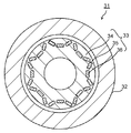
- FIG. 3 is a schematic view showing a configuration example of a variable magnetic flux motor.
- a rotor 33 is disposed in a stator 32.
- the permanent magnet of the first embodiment is disposed as a fixed magnet 35 and a variable magnet 36.
- the magnetic flux density (flux amount) of the variable magnet 36 can be varied. Since the direction of magnetization of the variable magnet 36 is orthogonal to the direction of the Q axis, the variable magnet 36 can be magnetized by the D axis current without being affected by the Q axis current.
- the rotor 33 is provided with a magnetization winding (not shown). When a current flows from the magnetization circuit to this magnetization winding, the magnetic field directly acts on the variable magnet 36.
- a coercive force suitable for the variable magnet 36 can be obtained.
- the coercivity may be controlled, for example, in the range of 100 kA / m or more and 500 kA / m or less by changing various conditions (aging treatment conditions and the like) of the manufacturing method described above.
- the variable magnetic flux motor 31 can output a large torque with a small device size, and thus is suitable for a motor for vehicles such as hybrid vehicles and electric vehicles that require high output and small size of the motor.
- FIG. 4 is a schematic view showing a configuration example of a generator.
- the generator 41 shown in FIG. 4 is provided with a stator (stator) 42 using the above-mentioned permanent magnet.
- a rotor 43 disposed inside the stator 42 is connected to a turbine 44 provided at one end of the generator 41 via a shaft 45.
- the turbine 44 is rotated by, for example, an externally supplied fluid. It is also possible to rotate the shaft 45 by transmitting dynamic rotation of regenerative energy or the like of a vehicle such as a car instead of the turbine 44 rotated by a fluid.
- Various known configurations can be adopted for the stator 42 and the rotor 43.
- the shaft 45 is in contact with a commutator (not shown) disposed on the side opposite to the turbine 44 with respect to the rotor 43, and the electromotive force generated by the rotation of the rotor 43 is a phase separation bus as an output of the generator 41. And it is boosted to the grid voltage and transmitted via the main transformer (not shown).
- the rotor 43 is charged by static electricity from the turbine 44 and axial current accompanying power generation. For this reason, the generator 41 is provided with a brush 46 for discharging the charge of the rotor 43.
- FIG. 5 is a schematic view showing a configuration example of a railway vehicle.
- a railway vehicle 100 shown in FIG. 5 includes a rotating electrical machine 101.
- the motor of FIG. 3, the generator of FIG. 4 or the like can be used.
- the rotating electrical machine 101 is driven by utilizing the power supplied from the overhead wire or the power supplied from the secondary battery mounted on the railway vehicle 100.
- the motor energy may be used as an electric motor (motor) that outputs the motor energy, or may be used as a generator (generator) that converts kinetic energy into electric power and supplies electric power to various loads in the railway vehicle 100.
- a highly efficient rotating electrical machine such as the rotating electrical machine of the embodiment, it is possible to travel a railway vehicle with energy saving.
- the rotating electrical machine may be mounted on a vehicle (another example of a vehicle) such as a hybrid vehicle or an electric vehicle.
- FIG. 6 is a schematic view showing a configuration example of a car.
- An automobile 200 shown in FIG. 6 includes a rotating electrical machine 201.
- the rotating electrical machine 201 the motor shown in FIG. 3 or the generator shown in FIG. 4 can be used.
- the rotating electrical machine is mounted as the rotating electrical machine 201
- the rotating electrical machine 201 may also be used as an electric motor for outputting the driving force of the automobile 200 or a generator for converting kinetic energy during traveling of the automobile 200 into electric power.
- the rotating electrical machine may be mounted on, for example, an industrial device (industrial motor), an air conditioner (air conditioner / hot water heater compressor motor), a wind power generator, or an elevator (winding machine).
- Example 1 After measuring each raw material so that it might become a composition shown in Table 1, the alloy ingot was produced by high frequency melting. The ingot was roughly crushed and then finely ground by a jet mill to prepare an alloy fine powder having an average particle diameter of 4 ⁇ m. The obtained fine powder was pressed at a pressing pressure of 1 t in a magnetic field of 2.0 T to obtain a green compact.
- the obtained green compact was sintered.
- the temperature was raised to 1210 ° C. in vacuum and held for 3 hours.
- solution heat treatment was performed by holding at 1160 ° C. for 12 hours in an Ar atmosphere, and cooled to room temperature at a rate of 170 ° C./minute.
- the sintered body after solution heat treatment is heat treated at 650 ° C. for 40 hours in Ar atmosphere as aging treatment, then gradually cooled to 300 ° C. at a cooling rate of 1 ° C./min and further cooled to room temperature did.
- a sintered magnet was obtained by the above steps.
- Example 2 After measuring each raw material so that it might become a composition shown in Table 1, the alloy ingot was produced by high frequency melting. The ingot was roughly crushed and then finely ground by a jet mill to prepare an alloy fine powder having an average particle diameter of 3 ⁇ m. The obtained fine powder was pressed at a pressing pressure of 1 t in a magnetic field of 2.0 T to obtain a green compact.
- the obtained green compact was sintered. In sintering, the temperature was raised to 1210 ° C. in Ar and held for 5 hours.
- solution heat treatment was performed by holding at 1150 ° C. for 12 hours in an Ar atmosphere, and cooled to room temperature at a rate of 170 ° C./minute.
- the sintered body after solution heat treatment is subjected to heat treatment at 670 ° C. for 20 hours in Ar atmosphere as aging treatment, and then gradually cooled to 400 ° C. at a cooling rate of 1.5 ° C./min. It cooled down.
- a sintered magnet was obtained by the above steps.
- Example 3 After measuring each raw material so that it might become a composition shown in Table 1, the alloy ingot was produced by high frequency melting. The ingot was roughly crushed and then finely ground by a jet mill to prepare an alloy fine powder having an average particle diameter of 4 ⁇ m. The obtained fine powder was pressed at a pressing pressure of 1 t in a magnetic field of 2.0 T to obtain a green compact.
- the obtained green compact was sintered. In sintering, the temperature was raised to 1210 ° C. in Ar and held for 5 hours.
- solution heat treatment was performed by holding at 1140 ° C. for 20 hours in an Ar atmosphere, and cooled to room temperature at a rate of 170 ° C./minute.
- the sintered body after solution heat treatment is subjected to heat treatment at 660 ° C. for 15 hours in Ar atmosphere as aging treatment, then gradually cooled to 200 ° C. at a cooling rate of 1 ° C./min and further cooled to room temperature did.
- a sintered magnet was obtained by the above steps.
- solution heat treatment was performed by holding at 1150 ° C. for 20 hours in an Ar atmosphere, and cooled to room temperature at a rate of 140 ° C./min.
- the sintered body after solution heat treatment is subjected to heat treatment at 720 ° C. for 40 hours in Ar atmosphere as aging treatment, gradually cooled to 400 ° C. at a cooling rate of 0.4 ° C./min, and further cooled to room temperature did.
- a sintered magnet was obtained by the above steps.
- the volume ratio of the TbCu 7- type crystal phase is 95% or more of the constituent phases of the main phase, and the dispersion of the Cu concentration of the TbCu 7- type crystal phase is 0.7 or more is there. Further, as apparent from Table 2, all of the sintered magnets of Examples 1 to 3 have high residual magnetization and coercivity suitable for a variable magnet. On the other hand, in the permanent magnet of Comparative Example 1, the volume ratio of the TbCu 7 crystal phase is low, and the residual magnetization is low.
Landscapes
- Engineering & Computer Science (AREA)
- Chemical & Material Sciences (AREA)
- Crystallography & Structural Chemistry (AREA)
- Inorganic Chemistry (AREA)
- Power Engineering (AREA)
- Manufacturing & Machinery (AREA)
- Mechanical Engineering (AREA)
- Hard Magnetic Materials (AREA)
- Powder Metallurgy (AREA)
Abstract
La présente invention concerne un aimant permanent exprimé par la formule de composition : RpFeqMrCusCo100-p-q-r-s. L'aimant permanent est pourvu de grains cristallins comportant une phase principale comprenant une phase cristalline de type TbCu7. Parmi les phases constitutives de la phase principale, le rapport volumique d'une phase cristalline de type TbCu7 n'est pas inférieur à 95 %.
Priority Applications (4)
| Application Number | Priority Date | Filing Date | Title |
|---|---|---|---|
| PCT/JP2017/033494 WO2019053886A1 (fr) | 2017-09-15 | 2017-09-15 | Aimant permanent, machine électrique rotative et véhicule |
| JP2019506211A JP6613010B2 (ja) | 2017-09-15 | 2017-09-15 | 永久磁石、回転電機、及び車両 |
| US16/283,879 US20190221338A1 (en) | 2017-09-15 | 2019-02-25 | Permanent magnet, rotary electrical machine, and vehicle |
| US17/375,064 US11676747B2 (en) | 2017-09-15 | 2021-07-14 | Permanent magnet, rotary electrical machine, and vehicle |
Applications Claiming Priority (1)
| Application Number | Priority Date | Filing Date | Title |
|---|---|---|---|
| PCT/JP2017/033494 WO2019053886A1 (fr) | 2017-09-15 | 2017-09-15 | Aimant permanent, machine électrique rotative et véhicule |
Related Child Applications (1)
| Application Number | Title | Priority Date | Filing Date |
|---|---|---|---|
| US16/283,879 Continuation US20190221338A1 (en) | 2017-09-15 | 2019-02-25 | Permanent magnet, rotary electrical machine, and vehicle |
Publications (1)
| Publication Number | Publication Date |
|---|---|
| WO2019053886A1 true WO2019053886A1 (fr) | 2019-03-21 |
Family
ID=65723535
Family Applications (1)
| Application Number | Title | Priority Date | Filing Date |
|---|---|---|---|
| PCT/JP2017/033494 Ceased WO2019053886A1 (fr) | 2017-09-15 | 2017-09-15 | Aimant permanent, machine électrique rotative et véhicule |
Country Status (3)
| Country | Link |
|---|---|
| US (2) | US20190221338A1 (fr) |
| JP (1) | JP6613010B2 (fr) |
| WO (1) | WO2019053886A1 (fr) |
Cited By (1)
| Publication number | Priority date | Publication date | Assignee | Title |
|---|---|---|---|---|
| WO2024071207A1 (fr) * | 2022-09-28 | 2024-04-04 | Tdk株式会社 | Dispositif de commande pour moteur, moteur, dispositif de commande pour générateur d'énergie, générateur d'énergie et éolienne |
Citations (4)
| Publication number | Priority date | Publication date | Assignee | Title |
|---|---|---|---|---|
| JPH02294447A (ja) * | 1989-05-09 | 1990-12-05 | Mitsubishi Steel Mfg Co Ltd | 永久磁石材料およびその製造方法 |
| JPH058562B2 (fr) * | 1982-04-26 | 1993-02-02 | Tokyo Shibaura Electric Co | |
| WO2016151622A1 (fr) * | 2015-03-23 | 2016-09-29 | 株式会社 東芝 | Aimant permanent, moteur et générateur |
| JP6081254B2 (ja) * | 2013-03-26 | 2017-02-15 | 株式会社東芝 | 永久磁石とそれを用いたモータおよび発電機 |
Family Cites Families (15)
| Publication number | Priority date | Publication date | Assignee | Title |
|---|---|---|---|---|
| JPS5810454B2 (ja) * | 1980-02-07 | 1983-02-25 | 住友特殊金属株式会社 | 永久磁石合金 |
| JPS63157844A (ja) * | 1986-12-18 | 1988-06-30 | Fuji Elelctrochem Co Ltd | 永久磁石材料の製造方法 |
| JPH058562A (ja) * | 1991-07-05 | 1993-01-19 | Mitsui Toatsu Chem Inc | 感熱昇華転写記録用色素、感熱転写用インキ組成物およ び熱転写シート |
| JPH0582319A (ja) | 1992-01-17 | 1993-04-02 | Toshiba Corp | 永久磁石 |
| EP1626418A3 (fr) | 2000-09-08 | 2007-11-07 | Shin-Etsu Chemical Co., Ltd. | Alliage de terre rare, aimant fritté de terre rare, et procédés de fabrication |
| JP2002083707A (ja) | 2000-09-08 | 2002-03-22 | Shin Etsu Chem Co Ltd | 希土類焼結磁石の製造方法 |
| US7713360B2 (en) | 2004-02-26 | 2010-05-11 | Shin-Etsu Chemical Co., Ltd. | Rare earth permanent magnet |
| JP4448713B2 (ja) | 2004-02-26 | 2010-04-14 | 信越化学工業株式会社 | 希土類永久磁石 |
| JP4965924B2 (ja) | 2006-07-24 | 2012-07-04 | 株式会社東芝 | 可変磁束ドライブシステム |
| JP4936820B2 (ja) | 2006-08-10 | 2012-05-23 | 株式会社東芝 | 可変磁束ドライブシステム |
| JP2011114236A (ja) | 2009-11-27 | 2011-06-09 | Toshiba Corp | 永久磁石およびその製造方法、モータ用永久磁石および永久磁石モータ |
| JP5526222B2 (ja) | 2010-03-30 | 2014-06-18 | 株式会社東芝 | 永久磁石とその製造方法、およびそれを用いたモータおよび発電機 |
| JP5558447B2 (ja) * | 2011-09-29 | 2014-07-23 | 株式会社東芝 | 永久磁石とそれを用いたモータおよび発電機 |
| WO2015044974A1 (fr) * | 2013-09-24 | 2015-04-02 | 株式会社 東芝 | Aimant permanent, moteur et générateur de puissance |
| WO2015140829A1 (fr) * | 2014-03-18 | 2015-09-24 | 株式会社 東芝 | Aimant permanent, moteur et générateur |
-
2017
- 2017-09-15 JP JP2019506211A patent/JP6613010B2/ja not_active Expired - Fee Related
- 2017-09-15 WO PCT/JP2017/033494 patent/WO2019053886A1/fr not_active Ceased
-
2019
- 2019-02-25 US US16/283,879 patent/US20190221338A1/en not_active Abandoned
-
2021
- 2021-07-14 US US17/375,064 patent/US11676747B2/en active Active
Patent Citations (4)
| Publication number | Priority date | Publication date | Assignee | Title |
|---|---|---|---|---|
| JPH058562B2 (fr) * | 1982-04-26 | 1993-02-02 | Tokyo Shibaura Electric Co | |
| JPH02294447A (ja) * | 1989-05-09 | 1990-12-05 | Mitsubishi Steel Mfg Co Ltd | 永久磁石材料およびその製造方法 |
| JP6081254B2 (ja) * | 2013-03-26 | 2017-02-15 | 株式会社東芝 | 永久磁石とそれを用いたモータおよび発電機 |
| WO2016151622A1 (fr) * | 2015-03-23 | 2016-09-29 | 株式会社 東芝 | Aimant permanent, moteur et générateur |
Cited By (1)
| Publication number | Priority date | Publication date | Assignee | Title |
|---|---|---|---|---|
| WO2024071207A1 (fr) * | 2022-09-28 | 2024-04-04 | Tdk株式会社 | Dispositif de commande pour moteur, moteur, dispositif de commande pour générateur d'énergie, générateur d'énergie et éolienne |
Also Published As
| Publication number | Publication date |
|---|---|
| US20190221338A1 (en) | 2019-07-18 |
| US20210343457A1 (en) | 2021-11-04 |
| JP6613010B2 (ja) | 2019-11-27 |
| US11676747B2 (en) | 2023-06-13 |
| JPWO2019053886A1 (ja) | 2019-11-07 |
Similar Documents
| Publication | Publication Date | Title |
|---|---|---|
| JP5504233B2 (ja) | 永久磁石とその製造方法、およびそれを用いたモータおよび発電機 | |
| JP6017673B2 (ja) | 永久磁石、モータ、発電機、および自動車 | |
| JP6518004B2 (ja) | 永久磁石、回転電機、及び車両 | |
| JP5996773B2 (ja) | 永久磁石、モータ、発電機、および自動車 | |
| JP2013074235A (ja) | 永久磁石とそれを用いたモータおよび発電機 | |
| JP5985738B1 (ja) | 永久磁石、モータ、および発電機 | |
| JP6105046B2 (ja) | 永久磁石、モータ、発電機、車、および永久磁石の製造方法 | |
| WO2019058977A1 (fr) | Matériau magnétique, aimant permanent, machine électrique rotative et véhicule | |
| US10480052B2 (en) | Permanent magnet, and motor and generator using the same | |
| CN107204224B (zh) | 永久磁铁、旋转电机及车辆 | |
| JP5710818B2 (ja) | 永久磁石、ならびにそれを用いたモータおよび発電機 | |
| JP6503078B2 (ja) | 永久磁石、回転電機、および車 | |
| JP6325744B2 (ja) | 永久磁石、モータ、および発電機 | |
| US11676747B2 (en) | Permanent magnet, rotary electrical machine, and vehicle | |
| JP7797333B2 (ja) | 永久磁石、回転電機、車両、及び航空機 | |
| JP7646593B2 (ja) | 永久磁石、回転電機、車両、及び航空機 | |
| JP5917601B2 (ja) | 永久磁石 | |
| JP6125687B2 (ja) | モータ、発電機、および自動車 | |
| JP2017168847A (ja) | 永久磁石、モータ、発電機、および車 |
Legal Events
| Date | Code | Title | Description |
|---|---|---|---|
| ENP | Entry into the national phase |
Ref document number: 2019506211 Country of ref document: JP Kind code of ref document: A |
|
| 121 | Ep: the epo has been informed by wipo that ep was designated in this application |
Ref document number: 17925429 Country of ref document: EP Kind code of ref document: A1 |
|
| NENP | Non-entry into the national phase |
Ref country code: DE |
|
| 122 | Ep: pct application non-entry in european phase |
Ref document number: 17925429 Country of ref document: EP Kind code of ref document: A1 |