WO2019054200A1 - Procédé et dispositif de traitement d'image - Google Patents
Procédé et dispositif de traitement d'image Download PDFInfo
- Publication number
- WO2019054200A1 WO2019054200A1 PCT/JP2018/032324 JP2018032324W WO2019054200A1 WO 2019054200 A1 WO2019054200 A1 WO 2019054200A1 JP 2018032324 W JP2018032324 W JP 2018032324W WO 2019054200 A1 WO2019054200 A1 WO 2019054200A1
- Authority
- WO
- WIPO (PCT)
- Prior art keywords
- prediction
- unit
- image
- component
- color difference
- Prior art date
- Legal status (The legal status is an assumption and is not a legal conclusion. Google has not performed a legal analysis and makes no representation as to the accuracy of the status listed.)
- Ceased
Links
Images






















Classifications
-
- H—ELECTRICITY
- H04—ELECTRIC COMMUNICATION TECHNIQUE
- H04N—PICTORIAL COMMUNICATION, e.g. TELEVISION
- H04N19/00—Methods or arrangements for coding, decoding, compressing or decompressing digital video signals
- H04N19/10—Methods or arrangements for coding, decoding, compressing or decompressing digital video signals using adaptive coding
- H04N19/102—Methods or arrangements for coding, decoding, compressing or decompressing digital video signals using adaptive coding characterised by the element, parameter or selection affected or controlled by the adaptive coding
- H04N19/103—Selection of coding mode or of prediction mode
- H04N19/105—Selection of the reference unit for prediction within a chosen coding or prediction mode, e.g. adaptive choice of position and number of pixels used for prediction
-
- H—ELECTRICITY
- H04—ELECTRIC COMMUNICATION TECHNIQUE
- H04N—PICTORIAL COMMUNICATION, e.g. TELEVISION
- H04N19/00—Methods or arrangements for coding, decoding, compressing or decompressing digital video signals
- H04N19/10—Methods or arrangements for coding, decoding, compressing or decompressing digital video signals using adaptive coding
- H04N19/102—Methods or arrangements for coding, decoding, compressing or decompressing digital video signals using adaptive coding characterised by the element, parameter or selection affected or controlled by the adaptive coding
- H04N19/117—Filters, e.g. for pre-processing or post-processing
-
- H—ELECTRICITY
- H04—ELECTRIC COMMUNICATION TECHNIQUE
- H04N—PICTORIAL COMMUNICATION, e.g. TELEVISION
- H04N19/00—Methods or arrangements for coding, decoding, compressing or decompressing digital video signals
- H04N19/10—Methods or arrangements for coding, decoding, compressing or decompressing digital video signals using adaptive coding
- H04N19/134—Methods or arrangements for coding, decoding, compressing or decompressing digital video signals using adaptive coding characterised by the element, parameter or criterion affecting or controlling the adaptive coding
- H04N19/157—Assigned coding mode, i.e. the coding mode being predefined or preselected to be further used for selection of another element or parameter
- H04N19/159—Prediction type, e.g. intra-frame, inter-frame or bidirectional frame prediction
-
- H—ELECTRICITY
- H04—ELECTRIC COMMUNICATION TECHNIQUE
- H04N—PICTORIAL COMMUNICATION, e.g. TELEVISION
- H04N19/00—Methods or arrangements for coding, decoding, compressing or decompressing digital video signals
- H04N19/10—Methods or arrangements for coding, decoding, compressing or decompressing digital video signals using adaptive coding
- H04N19/134—Methods or arrangements for coding, decoding, compressing or decompressing digital video signals using adaptive coding characterised by the element, parameter or criterion affecting or controlling the adaptive coding
- H04N19/167—Position within a video image, e.g. region of interest [ROI]
-
- H—ELECTRICITY
- H04—ELECTRIC COMMUNICATION TECHNIQUE
- H04N—PICTORIAL COMMUNICATION, e.g. TELEVISION
- H04N19/00—Methods or arrangements for coding, decoding, compressing or decompressing digital video signals
- H04N19/10—Methods or arrangements for coding, decoding, compressing or decompressing digital video signals using adaptive coding
- H04N19/169—Methods or arrangements for coding, decoding, compressing or decompressing digital video signals using adaptive coding characterised by the coding unit, i.e. the structural portion or semantic portion of the video signal being the object or the subject of the adaptive coding
- H04N19/17—Methods or arrangements for coding, decoding, compressing or decompressing digital video signals using adaptive coding characterised by the coding unit, i.e. the structural portion or semantic portion of the video signal being the object or the subject of the adaptive coding the unit being an image region, e.g. an object
- H04N19/176—Methods or arrangements for coding, decoding, compressing or decompressing digital video signals using adaptive coding characterised by the coding unit, i.e. the structural portion or semantic portion of the video signal being the object or the subject of the adaptive coding the unit being an image region, e.g. an object the region being a block, e.g. a macroblock
-
- H—ELECTRICITY
- H04—ELECTRIC COMMUNICATION TECHNIQUE
- H04N—PICTORIAL COMMUNICATION, e.g. TELEVISION
- H04N19/00—Methods or arrangements for coding, decoding, compressing or decompressing digital video signals
- H04N19/10—Methods or arrangements for coding, decoding, compressing or decompressing digital video signals using adaptive coding
- H04N19/169—Methods or arrangements for coding, decoding, compressing or decompressing digital video signals using adaptive coding characterised by the coding unit, i.e. the structural portion or semantic portion of the video signal being the object or the subject of the adaptive coding
- H04N19/182—Methods or arrangements for coding, decoding, compressing or decompressing digital video signals using adaptive coding characterised by the coding unit, i.e. the structural portion or semantic portion of the video signal being the object or the subject of the adaptive coding the unit being a pixel
-
- H—ELECTRICITY
- H04—ELECTRIC COMMUNICATION TECHNIQUE
- H04N—PICTORIAL COMMUNICATION, e.g. TELEVISION
- H04N19/00—Methods or arrangements for coding, decoding, compressing or decompressing digital video signals
- H04N19/10—Methods or arrangements for coding, decoding, compressing or decompressing digital video signals using adaptive coding
- H04N19/169—Methods or arrangements for coding, decoding, compressing or decompressing digital video signals using adaptive coding characterised by the coding unit, i.e. the structural portion or semantic portion of the video signal being the object or the subject of the adaptive coding
- H04N19/186—Methods or arrangements for coding, decoding, compressing or decompressing digital video signals using adaptive coding characterised by the coding unit, i.e. the structural portion or semantic portion of the video signal being the object or the subject of the adaptive coding the unit being a colour or a chrominance component
-
- H—ELECTRICITY
- H04—ELECTRIC COMMUNICATION TECHNIQUE
- H04N—PICTORIAL COMMUNICATION, e.g. TELEVISION
- H04N19/00—Methods or arrangements for coding, decoding, compressing or decompressing digital video signals
- H04N19/50—Methods or arrangements for coding, decoding, compressing or decompressing digital video signals using predictive coding
- H04N19/593—Methods or arrangements for coding, decoding, compressing or decompressing digital video signals using predictive coding involving spatial prediction techniques
-
- H—ELECTRICITY
- H04—ELECTRIC COMMUNICATION TECHNIQUE
- H04N—PICTORIAL COMMUNICATION, e.g. TELEVISION
- H04N19/00—Methods or arrangements for coding, decoding, compressing or decompressing digital video signals
- H04N19/70—Methods or arrangements for coding, decoding, compressing or decompressing digital video signals characterised by syntax aspects related to video coding, e.g. related to compression standards
-
- H—ELECTRICITY
- H04—ELECTRIC COMMUNICATION TECHNIQUE
- H04N—PICTORIAL COMMUNICATION, e.g. TELEVISION
- H04N19/00—Methods or arrangements for coding, decoding, compressing or decompressing digital video signals
- H04N19/80—Details of filtering operations specially adapted for video compression, e.g. for pixel interpolation
Definitions
- the present disclosure relates to an image processing apparatus and method, and more particularly to an image processing apparatus and method capable of suppressing a reduction in coding efficiency.
- inter-component linear prediction in order to improve the prediction performance of color difference intra prediction (see, for example, Non-Patent Document 1).
- inter-component linear prediction in order to improve prediction performance, a technique called multi-filter linear model prediction has been proposed in which the down sample filter used to generate the luminance component to be referenced is selected from four down sample filters. It was
- the application of the multi-filter mode was premised on the color difference format being 420 format. Therefore, the multi-filter mode described in Non-Patent Document 1 could not be applied to color difference formats other than the 420 format, such as the 422 format. Therefore, when the color difference format is other than the 420 format, there is a possibility that the coding efficiency may be reduced.
- the present disclosure has been made in view of such a situation, and makes it possible to suppress a reduction in coding efficiency.
- the image processing device uses the filter selected based on the information on the pixel position of the color difference component and the information on the color format from the pixel value of the reference image of the luminance component whose pixel position has been changed
- a prediction unit that predicts pixel values of color difference components by linear prediction and generates a prediction image of the color difference components, and a color difference component of encoded data obtained by encoding an image using the prediction image generated by the prediction unit
- a decoding unit that decodes the image.
- an image processing method of one aspect of the present technology from a pixel value of a reference image of a luminance component whose pixel position is changed using a filter selected based on information on a pixel position of a chrominance component and information on a color format, An image processing method of predicting pixel values of color difference components by linear prediction, generating a prediction image of color difference components, and decoding a color difference component of encoded data obtained by encoding the image using the generated prediction image is there.
- the image processing device uses the filter selected based on the information on the pixel position of the color difference component and the information on the color format from the pixel value of the reference image of the luminance component whose pixel position has been changed.
- a prediction unit that predicts pixel values of color difference components by linear prediction, and generates a predicted image of the color difference components; and a coding unit that codes color difference components of an image using the predicted image generated by the prediction unit And an image processing apparatus.
- An image processing method uses a filter selected based on information on pixel positions of color difference components and information on color formats from pixel values of reference images of luminance components whose pixel positions have been changed.
- a pixel value of a color difference component is predicted by linear prediction, a predicted image of the color difference component is generated, and the color difference component of the image is encoded using the generated predicted image.
- pixels of a reference image of a luminance component whose pixel position is changed using a filter selected based on information on pixel positions of color difference components and information on color format are predicted by linear prediction to generate a predicted image of the chrominance component, and the generated predicted image is used to decode the chrominance component of the encoded data in which the image is encoded.
- a reference image of a luminance component reference image whose pixel position is changed using a filter selected based on information on pixel positions of color difference components and information on color format. From the pixel values, the pixel values of the color difference component are predicted by linear prediction, a predicted image of the color difference component is generated, and the color difference component of the image is encoded using the generated predicted image.
- an image can be processed.
- reduction in coding efficiency can be suppressed.
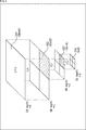
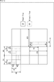
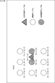
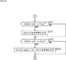
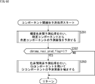
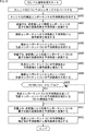
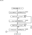
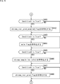
- FIG. 7 is a diagram showing pixel positions of luminance components of multi-filter linear model prediction. It is a figure which shows the example of the syntax regarding inter-component linear prediction. It is a figure which shows the example of the syntax regarding inter-component linear prediction. It is a flowchart explaining the example of the flow of the inter-component linear prediction process. It is a figure for demonstrating the subject of the linear prediction between components in a prior art. It is an explanatory view for explaining an outline of recursive block division about CU.
- FIG. 10 is a diagram illustrating an example of semantics regarding a block. It is a block diagram which shows the main structural examples of an image decoding apparatus. It is a figure which shows the example of the syntax of color difference sample positional information. It is a flowchart explaining the example of the flow of image decoding processing. It is a flowchart explaining the example of the flow of decoding processing.
- FIG. 10 is a diagram illustrating an example of semantics regarding a block. It is a block diagram which shows the main structural examples of an image decoding apparatus. It is a figure which shows the example of the syntax of color difference sample positional information. It is a flowchart explaining the example of the flow of image decoding processing. It is a flowchart explaining the example of the flow of decoding processing.
- FIG. 10 is a diagram illustrating an example of semantics regarding a block. It is a block diagram which shows the main structural examples of an image decoding apparatus. It is a figure which shows the example of the syntax of color difference sample positional information. It is
- FIG. 19 is a flowchart illustrating an example of the flow of decoding processing, following FIG. 18; It is a figure which shows the example of the syntax regarding inter-component linear prediction. It is a figure which shows the example of the collocated block of a brightness
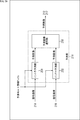
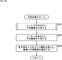
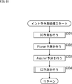
- FIG. 58 is a flowchart following to FIG. 57, illustrating an example of the flow of encoding processing; It is a block diagram which shows the main structural examples of a prediction part. It is a flowchart explaining the example of the flow of prediction processing. It is a flowchart explaining the example of the flow of an intra prediction process. It is a flowchart explaining the example of the flow of CU level coding processing.
- FIG. 58 is a flowchart following to FIG. 57, illustrating an example of the flow of encoding processing; It is a block diagram which shows the main structural examples of a prediction part. It is a flowchart explaining the example of the flow of prediction processing. It is a flowchart explaining the example of the flow of an intra prediction process. It is a flowchart explaining the example of the flow of CU level coding processing.
- FIG. 58 is a flowchart following to FIG. 57, illustrating an example of the flow of encoding processing; It is a block diagram which shows the main
- FIG. 63 is a flowchart continued from FIG. 62, illustrating an example of the flow of CU level encoding processing. It is a flowchart explaining the example of the flow of decoding processing.
- FIG. 65 is a flowchart following to FIG. 64 for explaining an example of the flow of decoding processing; It is a figure which shows the example of the syntax regarding inter-component linear prediction. It is a block diagram which shows the main structural examples of CC estimation part. It is a flowchart explaining the example of the flow of the inter-component linear prediction process. It is a flowchart explaining the example of the flow of CU level decoding processing. It is a flowchart explaining the example of the flow of an encoding process. It is a flowchart following FIG.
- FIG. 70 explaining the example of the flow of an encoding process. It is a flowchart explaining the example of the flow of CU level coding processing. 73 is a flowchart illustrating an example of the flow of CU level coding processing, following FIG. 72.
- FIG. It is a block diagram showing an example of main composition of a computer. It is a block diagram showing an example of a schematic structure of a television set. It is a block diagram which shows an example of a rough structure of a mobile telephone. It is a block diagram which shows an example of a rough structure of a recording and reproducing apparatus. It is a block diagram showing an example of rough composition of an imaging device. It is a block diagram which shows an example of a rough structure of a video set.
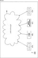
- FIG. 1 is a block diagram showing an example of a schematic configuration of a network system.
- Inter-component linear prediction> ⁇ About inter-component linear prediction (CCLMP)>
- CCLMP Cross Component Linear Model Prediction
- This inter-component linear prediction (CCLMP) is also referred to as inter-component prediction (CCP (Cross Component Prediction)).
- CCP Cross Component Linear Model Prediction
- luminance signal and the luminance component are also referred to as a luminance component.
- the color difference signal and the color difference component are also referred to as a color difference component.
- CCLMP CCP
- pixel values of the block to be predicted on component A color difference component C
- component A color difference component C
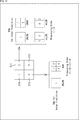
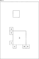
- the parameters ⁇ and ⁇ of the linear model are the adjacent decoded pixel groups of the block to be predicted of component A (color difference component C) shown in A of FIG. 2 and their co-located positions shown in B of FIG. Is derived by linear regression (or least squares method) from the decoded pixel group of the component B (the luminance component Y in the example of FIG. 2B).
- ⁇ is derived by the following equation (2)
- ⁇ is derived by the following equation (3).
- the component to be predicted is also referred to as a prediction target component
- the component that is the reference source at the time of prediction is also referred to as a reference component.
- N is the number of samples of the adjacent decoded pixel group of the chrominance component C (or the decoded pixel group of the reduced luminance component Y corresponding to the chrominance component C (reduced luminance decoded pixel group) Number of samples).
- C (n) represents the n-th sample of the adjacent decoded pixel group of the chrominance component C
- L (n) represents the n-th sample of the reduced luminance decoded pixel group corresponding to the chrominance component C.
- chrominance format also referred to as chrominance array type ChromaArrayType
- a luminance component signal Rec L '[x, y of reduced resolution (at the co-located position) corresponding to the chrominance component signal at the (x, y) position ] Is derived by applying, for example, the down sample filter shown in the following equation (4) with the decoded pixel group Rec L [2x, 2y] of the luminance component at the original resolution as a center.
- MCLMP Multi-class linear prediction
- MCLMP Multi-Class Linear Model Prediction
- MMLMP Multi Model Linear Model Prediction
- the prediction signal Pred C [x, y] of the chrominance component is derived by the linear prediction equation corresponding to each class.
- the threshold value Thr is, for example, an average value of the reduced luminance decoded pixel group Rec L '[x, y].
- ⁇ About the multi filter mode (MFLMP)>
- MFLMP multifilter linear model prediction
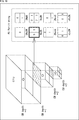
- the pixel positions (sample positions) of the luminance component are as illustrated in A to E in FIG. 4, respectively.
- 4 corresponds to equation (4)
- B in FIG. 4 corresponds to equation (6)
- C in FIG. 4 corresponds to equation (7)
- D in FIG. 4 corresponds to equation (8)
- E in FIG. 4 corresponds to the equation (9).
- circles indicate pixel positions of the luminance component
- stars indicate pixel positions of the luminance component used in the down-sampling filter.
- CCLMP performs linear prediction of prediction residuals between two chrominance components (linear prediction of prediction residuals from Cb components to Cr components (U components to V components)) Cb / Cr residual prediction (Cb ⁇ There is a technology called to-Cr Residual Prediction).
- pred Cr [x, y] represents a Cr predicted image predicted from the luminance component by CCLMP represented by equation (1) or equation (6).
- pred Cr * [x, y] is a prediction residual resi obtained by inverse quantization / inverse conversion of the transform coefficient coef Cb of the Cb component from the Cr predicted image pred Cr [x, y] obtained from the luminance component
- a Cr predicted image corrected by adding ⁇ ⁇ resi Cb [x, y] multiplied by Cb [x, y] by a weighting factor ⁇ , that is, a corrected Cr predicted image is represented.
- the parameter ⁇ of the linear model is derived by linear regression (or least squares method) from the adjacent decoded pixels of the prediction target block of the Cr component and the decoded pixels of the Cb component at the co-located position Ru. For example, ⁇ is determined by equation (11).
- N represents the number of samples of the adjacent decoded pixel group of the Cr component.
- Cr (n) represents the n-th sample of the adjacent decoded pixel group of Cr component
- Cb (n) represents n of the adjacent decoded pixel group of Cb component located at the co-located position of the adjacent decoded pixel group of Cr component.
- ⁇ in equation (11) is a value of ⁇ (Cb (n) ⁇ Cb (n)) >> 9.
- Non-Patent Document 1 An example of a syntax table regarding CCLMP and its extended mode (multiclass mode (MCLMP), multifilter mode (MFLMP)) in Non-Patent Document 1 is shown in FIGS.
- MCLMP multiclass mode
- MFLMP multifilter mode
- cclmp_enabled_flag Inter-component linear prediction enabled flag. For example, “0” indicates that it can not be used, and “1” indicates that it can be used.
- cclmp_flag inter-component linear prediction flag. For example, “0” indicates that inter-component linear prediction is not used, and "1" indicates that inter-component linear prediction is used.
- intra_chroma_pred_mode This is an identifier for identifying the mode number in the chrominance intra prediction mode candidate list intraPredCandListC.
- mclmp_flag multi class mode flag (MCLMP flag). For example, "0" indicates one class mode (single class mode), and "1" indicates two class mode (multi class mode).
- mflmp_flag multi filter mode flag (MFLMP flag). For example, "0" indicates that the MFLMP mode is off, and "1" indicates changing the down sample filter.
- mflmp_idx multi filter mode identifier (MFLMP identifier). It is control information which specifies which down sample filter to use.
- Non-Patent Document 1 has, for example, the following features.
- Non-Patent Document 1 the application of the multi-filter mode is premised on the color difference format being the 420 format, and the other color difference formats (for example, the 422 format) are not considered. Therefore, it was difficult to apply the multi filter mode described in Non-Patent Document 1 to the 422 format. Therefore, there is a possibility that the coding efficiency may be reduced.
- the color difference format is 444 format
- the resolutions of the luminance component and the color difference component are the same. Therefore, it is not necessary to generate the luminance component signal RecL '[x, y] to be referred to in linear prediction of the chrominance component signal by the down sample filter, and the decoded pixel group RecL [x, y] of the luminance component at the original resolution Can be used as it is. Therefore, when the color difference format is 444 format, encoding / decoding of control information related to the multi filter mode is redundant. Therefore, there is a possibility that the coding efficiency may be reduced.
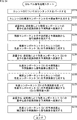
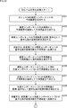
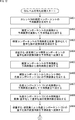
- step S11 the decoder parses syntax groups related to a CU to be decoded (also referred to as a current CU) from coded data.
- step S12 the decoder generates a predicted image of the luminance component.
- step S13 the decoder converts the transform coefficients of the luminance component into prediction residuals by inverse quantization and inverse transform.
- step S14 the decoder restores the decoded image from the prediction residual and the prediction image of the luminance component.
- step S15 the decoder generates a predicted image of the chrominance component (Cb) from the decoded image of the luminance component.
- step S16 the decoder converts the transform coefficients of the chrominance component (Cb) into prediction residuals by inverse quantization and inverse transform.
- step S17 the decoder restores the decoded image from the prediction residual of the chrominance component (Cb) and the predicted image.
- step S18 the decoder generates a predicted image of chrominance components (Cr) from the decoded image of the luminance component.
- step S19 the decoder converts the transform coefficients of the chrominance component (Cr) into prediction residuals by inverse quantization and inverse transform.
- step S20 the decoder uses the prediction residual of the chrominance component (Cb) to correct the prediction image of the chrominance component (Cr) (residue prediction between Cb / Cr).
- step S21 the decoder restores a decoded image from the prediction residual of the chrominance component (Cr) and the corrected predicted image.
- step S15 generation of a predicted image of a Cb component
- step S18 generation of a predicted image of Cr component
- step S20 correction of the prediction image of the Cr component
- step S16 generation of the prediction residual of the Cr component
- inter-component prediction has inter-component dependencies.
- the delay may be further increased as compared to the decoding of the Cb component.
- Non-Patent Document 1 has a problem as shown in FIG.
- AVC Advanced Video Coding
- a macroblock is a block having a uniform size of 16x16 pixels.
- HEVC High Efficiency Video Coding
- a CU a processing unit having a variable size, which is formed by recursively dividing an LCU (Largest Coding Unit) which is a largest coding unit.
- the maximum size of a selectable CU is 64x64 pixels.
- the minimum size of a selectable CU is 8x8 pixels.
- the CU of the smallest size is called SCU (Smallest Coding Unit).
- the maximum size of the CU is not limited to 64x64 pixels, and may be a block size such as larger 128x128 pixels or 256x256 pixels.
- the prediction process for predictive coding is performed in a processing unit (prediction unit) called PU (Prediction Unit).
- a PU is formed by dividing a CU with one of several division patterns.
- PU is composed of processing units (predicted blocks) called PB (Prediction Blocks) for each of luminance (Y) and color differences (Cb, Cr).
- PB Prediction Blocks
- orthogonal transformation processing is performed in a processing unit (transformation unit) called TU (Transform Unit).
- a TU is formed by dividing a CU or PU to a certain depth.
- the TU is composed of a processing unit (transform block) called TB (Transform Block) for each luminance (Y) and each color difference (Cb, Cr).
- FIG. 9 is an explanatory diagram for describing an overview of recursive block division for a CU in HEVC.
- the whole of one quadtree is called a CTB (Coding Tree Block), and a logical unit corresponding to the CTB is called a CTU (Coding Tree Unit).
- C01 which is a CU having a size of 64 ⁇ 64 pixels is shown as an example.
- the division depth of C01 is equal to zero. This means that C01 is the root of CTU and corresponds to LCU.
- the LCU size may be specified by parameters encoded in a Sequence Parameter Set (SPS) or a Picture Parameter Set (PPS).
- SPS Sequence Parameter Set
- PPS Picture Parameter Set
- the CU C02 is one of four CUs divided from C01 and has a size of 32 ⁇ 32 pixels.
- the division depth of C02 is equal to one.
- the CU C03 is one of four CUs divided from C02, and has a size of 16 ⁇ 16 pixels.
- the division depth of C03 is equal to two.
- the CU C04 is one of four CUs divided from C03, and has a size of 8 ⁇ 8 pixels.
- the division depth of C04 is equal to three.
- a CU is formed by recursively dividing an image to be encoded.
- the depth of division is variable. For example, a flat image area, such as a blue sky, may be set to a larger size (ie, smaller depth) CU.
- CUs of smaller size ie, greater depth
- each of the set CUs becomes a processing unit of the encoding process.
- ⁇ Setting of PU to CU> PU is a processing unit of prediction processing including intra prediction and inter prediction.
- a PU is formed by dividing a CU with one of several division patterns.
- FIG. 10 is an explanatory diagram for describing setting of a PU in the CU shown in FIG.
- eight types of divided patterns are shown: 2Nx2N, 2NxN, Nx2N, NxN, 2NxnU, 2NxnD, nLx2N, and nRx2N.
- intra prediction two types, 2Nx2N and NxN, can be selected (NxN can be selected only by the SCU).
- inter prediction when asymmetric motion segmentation is enabled, all eight types of segmentation patterns can be selected.
- TU is a processing unit of orthogonal transformation processing.
- a TU is formed by dividing a CU (each PU in a CU for an intra CU) to a certain depth.
- FIG. 11 is an explanatory diagram for describing setting of a TU in the CU shown in FIG.
- TU, T01 has a size of 32x32 pixels, and the depth of its TU partition is equal to zero.
- the TU, T02 has a size of 16x16 pixels, and the depth of its TU partition is equal to one.
- the TU T03 has a size of 8 ⁇ 8 pixels, and the depth of its TU partition is equal to two.
- What kind of block division is performed to set blocks such as CU, PU, and TU described above to an image is typically determined based on comparison of costs that affect coding efficiency. For example, the encoder compares the cost between a CU of one 2Mx2M pixel and a CU of four MxM pixels, and if setting a CU of four MxM pixels has a higher coding efficiency, a CU of 2Mx2M pixels Decide to divide into 4 CUs of M x M pixels.
- FIG. 12 is an explanatory diagram for describing a scanning order of CUs and PUs. In the upper left of FIG. 12, four CUs C10, C11, C12, and C13 that can be included in one CTB are shown. The numbers in the box of each CU represent the order of processing.
- the encoding process is performed in the order of C10 which is the upper left CU, C11 which is the upper right CU, C12 which is the lower left CU, and C13 which is the lower right CU.
- C11 which is the upper right CU
- C12 which is the lower left CU
- C13 which is the lower right CU.
- one or more PUs for intra prediction that may be set to C12 that is a CU are shown. As indicated by the numbers in the boxes of these PUs, the PUs are also scanned from left to right, top to bottom.
- the following description may be made using “blocks” as partial areas or processing units of an image (picture) (it is not a block of a processing unit).
- the “block” in this case indicates an arbitrary partial area in the picture, and the size, shape, characteristics, and the like of the partial area are not limited. That is, the “block” in this case includes, for example, any partial area (processing unit), such as TB, TU, PB, PU, SCU, CU, LCU (CTB), subblock, macroblock, tile, or slice. Shall be included.
- the block structure of encoding / decoding of image data is arbitrary, and is not limited to the above-mentioned example.
- the following quad tree plus binary tree (QTBT) structure may be applied.
- CU, PU, and TU Transform Unit
- FIG. 13 are the CU, PU, and QTBT described in JVET-C0024, “EE 2.1: Quadtree plus binary tree structure integration with JEM tools”, and It is TU.
- the shape of the CU may be rectangular as well as square.
- the size of the CU (horizontal size w x vertical size h) is 128x128, 64x64, 32x32, 16x16, 8x8, as shown in FIG.
- TU includes a conversion block of luminance (Y) and a conversion block of chrominance (Cb / Cr).
- the color format is 4: 2: 0 (for example, YUV420)
- the ratio of the picture size of the color difference to the picture size of the luminance is 1/2 in both the vertical width and the horizontal width. Therefore, if the luminance conversion block size is 8x4, the corresponding color difference conversion block size is 4x2.
- the color format is 4: 2: 2 (for example, YUV422)
- the ratio of the picture size of the color difference to the picture size of the luminance is 1/2 in the vertical width and 1 in the horizontal width. Therefore, if the luminance conversion block size is 8x4, the corresponding color difference conversion block size is 8x2.
- the ratio of the picture size of the color difference to the picture size of the luminance is 1 in the vertical width and 1 in the horizontal width. Therefore, if the luminance conversion block size is 8x4, the corresponding chrominance conversion block size is 8x4.
- the I slice may be encoded as separate CUs for luminance (Y) and chrominance (Cb / Cr).
- Y luminance
- Cb / Cr chrominance
- FIG. 14 shows an example of the semantics of the information on these blocks in JEM.
- the present technology can also be applied to image coding and image decoding of the QTBT structure as described above.
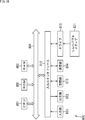
- FIG. 15 is a block diagram illustrating an example of a configuration of an image decoding device which is an aspect of the image processing device to which the present technology is applied.
- the image decoding apparatus 100 shown in FIG. 15 is an apparatus for decoding encoded data in which a prediction residual between an image and its predicted image is encoded, such as AVC or HEVC.
- the image decoding apparatus 100 implements the technology proposed for HEVC and the technology proposed for JVET (Joint Video Exploration Team).
- the image decoding apparatus 100 includes a decoding unit 111, an inverse quantization unit 112, an inverse conversion unit 113, a prediction unit 114, an operation unit 115, a frame memory 116, and a loop filter unit 117.
- the image decoding apparatus 100 is an apparatus for generating a moving image # 2 by decoding the input encoded data # 1 (bitstream).
- the decoding unit 111 performs a process related to image decoding. For example, the decoding unit 111 receives the encoded data # 1 as an input, performs variable-length decoding of syntax values of each syntax element from the bit string of the encoded data # 1 according to the definition of the syntax table, and converts the parameters Configured to derive.
- Parameters derived from syntax elements and syntax values of syntax elements include, for example, information such as header information Hinfo, prediction mode information Pinfo, conversion information Tinfo, residual information Rinfo, and filter information Finfo. These pieces of information are described below.
- the header information Hinfo includes, for example, header information such as video parameter set (VPS) / sequence parameter set (SPS) / picture parameter set (PPS) / slice header (SH).
- the header information Hinfo includes, for example, image size (horizontal width PicWidth, vertical width PicHeight), bit depth (brightness bitDepthY, color difference bitDepthC), color difference array type ChromaArrayType, CU size maximum value MaxCUSize / minimum value MinCUSize, quadtree division ( Also referred to as maximum depth MaxQdepth / minimum depth MinQTDepth of Quad-tree division, maximum depth MaxBTDepth / minimum depth MinBTDepth of binary tree division (Binary-tree division), maximum value MaxTSSize (maximum conversion skip block size of conversion skip block) And information that defines the on / off flag (also referred to as a valid flag) of each encoding tool.
- the on-off flag of the encoding tool included in the header information Hinfo there is an on-off flag related to conversion and quantization processing described below.
- the on / off flag of the encoding tool can also be interpreted as a flag indicating whether or not the syntax related to the encoding tool is present in the encoded data. Also, when the value of the on / off flag is 1 (true), it indicates that the encoding tool is usable, and when the value of the on / off flag is 0 (false), the encoding tool is not usable. Show. Note that the interpretation of the flag value may be reversed.
- Inter-component prediction enabled flag flag information indicating whether inter-component prediction (also referred to as CCP (Cross-Component Prediction, CC prediction) can be used). For example, if this flag information is “1” (true), it is indicated that it can be used, and if it is “0” (false), it is indicated that it is not usable.
- This CCP is also referred to as inter-component linear prediction (CCLM or CCLMP).
- the prediction mode information Pinfo includes, for example, information such as size information PBSize (prediction block size) of a processing target PB (prediction block), intra prediction mode information IPinfo, motion prediction information MVinfo, and the like.
- the intra prediction mode information IPinfo includes, for example, prev_intra_luma_pred_flag, mpm_idx, rem_intra_pred_mode in JCTVC-W 1005, 7.3.8.5 Coding Unit syntax, and luminance intra prediction mode IntraPredMode Y derived from the syntax and the like.
- intra prediction mode information IPinfo for example, inter-component prediction flag (ccp_flag (cclmp_flag)), multiclass linear prediction mode flag (mclm_flag), color difference sample position type identifier (chroma_sample_loc_type_idx), color difference MPM identifier (chroma_mpm_idx), and , Luminance intra prediction mode (IntraPredModeC) and the like derived from these syntaxes.
- inter-component prediction flag ccp_flag (cclmp_flag)
- mclm_flag multiclass linear prediction mode flag
- chroma_sample_loc_type_idx color difference MPM identifier
- Luminance intra prediction mode Luminance intra prediction mode
- the multiclass linear prediction mode flag (mclm_flag) is information on a mode of linear prediction (linear prediction mode information). More specifically, the multi-class linear prediction mode flag (mclm_flag) is flag information indicating whether or not to set the multi-class linear prediction mode. For example, “0” indicates one class mode (single class mode) (for example, CCLMP), and “1” indicates two class mode (multiclass mode) (for example, MCLMP) .
- the chrominance sample position type identifier (chroma_sample_loc_type_idx) is an identifier that identifies the type of pixel position of the chrominance component (also referred to as a chrominance sample position type). For example, when the color difference array type (ChromaArray Type), which is information on the color format, indicates the 420 type, the color difference sample position type identifier is assigned as follows.
- This chrominance sample position type identifier (chroma_sample_loc_type_idx) is transmitted (stored in) as information (chroma_sample_loc_info ()) on the pixel position of the chrominance component, as in the syntax shown in FIG. 16, for example.
- the chrominance MPM identifier (chroma_mpm_idx) is an identifier that indicates which prediction mode candidate in the chrominance intra prediction mode candidate list (intraPredModeCandListC) is designated as the chrominance intra prediction mode.
- the information included in the prediction mode information Pinfo is optional, and information other than these pieces of information may be included.
- the conversion information Tinfo includes, for example, the following information.
- the information included in the conversion information Tinfo is optional, and information other than these pieces of information may be included.
- Conversion skip flag (ts_flag): a flag indicating whether (reverse) primary conversion and (reverse) secondary conversion should be skipped.
- Scan identifier (scanIdx) Quantization parameter (qp) Quantization matrix (scaling_matrix (eg, JCTVC-W1005, 7.3.4 Scaling list data syntax))
- the residual information Rinfo includes, for example, the following syntax.
- cbf (coded_block_flag): Residual data presence / absence flag last_sig_coeff_x_pos: Last non-zero coefficient X coordinate last_sig_coeff_y_pos: Last non-zero coefficient Y coordinate coded_sub_block_flag: Subblock non-zero coefficient presence / absence flag sig_coeff_flag: Non-zero coefficient presence / absence flag gr1_flag: Non-zero coefficient level Flag indicating whether it is greater than 1 (also called GR1 flag)
- gr2_flag flag indicating whether the level of non-zero coefficient is greater than 2 (also called GR2 flag) sign_flag: A sign indicating the positive or negative of a nonzero coefficient (also called a sign code) coeff_abs_level_remaining: residual level of nonzero coefficient (also called nonzero coefficient residual level) Such.
- the filter information Finfo includes, for example, control information related to each filter process shown below, a picture to which each filter is applied, information specifying an area in the picture, filter on / off control information in CU units, slice , And filter on / off control information on tile boundaries.
- DPF deblocking filter
- ALF adaptive loop filter
- the decoding unit 111 refers to the residual information Rinfo to derive a quantized transform coefficient level level of each coefficient position in each transform block. Further, the decoding unit 111 supplies the header information Hinfo obtained by decoding, the prediction mode information Pinfo, the quantization conversion coefficient level level, the conversion information Tinfo, and the filter information Finfo to each block. Specifically, it is as follows.
- the header information Hinfo is supplied to the inverse transform unit 113, the inverse quantization unit 112, the prediction unit 114, and the loop filter unit 117.
- the prediction mode information Pinfo is supplied to the prediction unit 114.
- the quantized transformation coefficient level level is supplied to the inverse quantization unit 112.
- the transform information Tinfo is supplied to the inverse transform unit 113 and the inverse quantization unit 112.
- the filter information Finfo is supplied to the loop filter unit 117.
- the decoding unit 111 parses and decodes information on the inter-component linear prediction included in the encoded data, and acquires the information.
- the information on the inter-component linear prediction may be any information on the inter-component linear prediction.
- control information may be included to control processing related to inter-component linear prediction.
- the control information on the inter-component linear prediction may be any control information on the inter-component linear prediction.
- the above-described inter-component prediction enabled flag ccp_enabled_flag
- inter-component prediction flag ccp_flag
- multi-class linear prediction mode flag mclm_flag
- color difference array type ChromaArrayType
- color difference sample position type identifier chroma_sample_loc_type_idx
- the decoding unit 111 supplies the acquired information on the inter-component linear prediction to the prediction unit 114. Therefore, the prediction unit 114 can execute the process related to inter-component linear prediction based on the information.
- the dequantization part 112 performs the process regarding dequantization.
- the inverse quantization unit 112 receives the conversion information Tinfo and the quantization conversion coefficient level level supplied from the decoding unit 111, and scales the value of the quantization conversion coefficient level level based on the conversion information Tinfo (inverse quantum , And output the transform coefficient Coeff_IQ after inverse quantization to the inverse transform unit 113.
- the inverse conversion unit 113 performs processing relating to inverse conversion.
- the inverse transformation unit 113 receives the transformation coefficient Coeff_IQ and the transformation information Tinfo, applies an inverse transformation to the transformation coefficient Coeff_IQ based on the transformation information Tinfo, and derives a prediction residual D ′, and performs an operation It is configured to output to the unit 115.
- the arithmetic unit 115 performs processing concerning addition of information on an image. For example, with the prediction residual D ′ supplied from the inverse transformation unit 113 and the prediction image P supplied from the prediction unit 114 as an input, the calculation unit 115 receives prediction residuals as shown in the following equation (12). The difference D ′ and the prediction image P (prediction signal) corresponding to the prediction residual D ′ are added to derive and output a local decoded image R local .
- the prediction unit 114 performs processing relating to generation of a predicted image. For example, the prediction unit 114 receives the prediction mode information Pinfo, and the decoded image R ′ after the filter stored in the frame memory 116 specified by the prediction mode information Pinfo by the prediction method specified by the prediction mode information Pinfo.
- the prediction image P is generated using (or the decoded image R before filtering) as a reference image, and is output to the calculation unit 115.
- the loop filter unit 117 performs processing related to loop filter processing. For example, the loop filter unit 117 reads the decoded image R from the frame memory 116, and generates a decoded image R ′ after filtering by loop filter processing specified by the filter information Finfo. Also, the loop filter unit 117 supplies the decoded image R ′ after filtering to the frame memory 116.
- the loop filter processing performed by the loop filter unit 117 includes a deblocking filter (DBF (DeBlocking Filter)), a pixel adaptive offset (SAO (Sample Adaptive Offset)), and an adaptive loop filter (ALF (Adaptive Loop Filter)). And other linear and non-linear filters (such as Wiener filters, bilateral filters, etc.).
- the frame memory 116 performs processing related to storage of data related to an image. For example, the frame memory 116 receives the locally decoded image R local supplied from the operation unit 115, reconstructs the decoded image R for each picture unit, and stores the reconstructed image R in a buffer in the frame memory 116. The frame memory 116 reads the decoded image R from the buffer and supplies the read image R to the loop filter unit 117.
- the frame memory 116 stores the loop-filtered decoded image R ′ supplied from the loop filter unit 117 into a buffer in the frame memory 116.
- the frame memory 116 reads the decoded image R designated by the prediction mode information Pinfo of the prediction unit 114 or the decoded image R ′ after filtering from the buffer as a reference image, and supplies the read image to the prediction unit 114. Further, the frame memory 116 may store header information Hinfo, prediction mode information Pinfo, conversion information Tinfo, filter information Finfo, and the like related to generation of a decoded image in a buffer in the frame memory.
- the frame memory 116 is configured to perform the various processes as described above.
- the decoding unit 111 to the calculation unit 115 operate as a decoding unit that decodes the color difference component of the encoded data in which the image is encoded, using the predicted image generated by the prediction unit 114.
- the image decoding apparatus 100 performs processing of decoding encoded data in which data relating to an image supplied from, for example, the encoding side is encoded by performing image decoding processing.
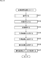
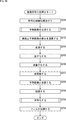
- step S101 the decoding unit 111 decodes the input encoded data (bit stream), and acquires data related to an image.
- the data for this image is quantized. That is, quantization coefficients are obtained.
- step S102 the inverse quantization unit 112 performs inverse quantization, which is inverse processing of quantization performed on the encoding side, on the quantization coefficient obtained in step S101, and obtains a transform coefficient Coeff_IQ.
- step S103 the inverse transformation unit 113 performs inverse transformation processing, which is the inverse processing of the transformation processing performed on the encoding side, on the transform coefficient Coeff_IQ obtained by the processing in step S102, and the prediction residual D ′.
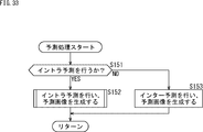
- step S104 the prediction unit 114 executes prediction processing, refers to the reference image stored in the frame memory 116, and generates a predicted image P by the prediction method specified by the encoding side.
- step S105 the operation unit 115 adds the prediction residual D ′ obtained by the process of step S103 and the predicted image P obtained by the process of step S104 as shown in equation (12), and generates a locally decoded image. Deriving R local The operation unit 115 outputs this local decoded image R local as a decoded image.
- step S106 the frame memory 116 stores the locally decoded image R local obtained by the process of step S105.
- step S107 the loop filter unit 117 performs predetermined filter processing on the local decoded image stored in the frame memory 116. Note that the locally decoded image after filtering is stored in the frame memory 116.
- step S107 ends, the image decoding process ends.
- FIG. 20 is an example of a syntax table of coding_unit () corresponding to the flowcharts of FIGS. 18 and 19.
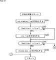
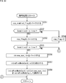
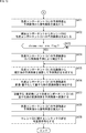
- step S121 the decoding unit 111 parses the inter-component prediction enabled flag ccp_enabled_flag from the encoded data and decodes it (acquires the inter-component prediction enabled flag ccp_enabled_flag from the encoded data).
- step S122 the decoding unit 111 determines whether condition 1 shown in the following equation (13) is satisfied.
- the decoding unit 111 determines whether the inter-component prediction enabled flag ccp_enabled_flag is 1 (true). If it is determined that the above equation (13) is satisfied (if it is determined that the ccp_enabled_flag is 1 (true)), the processing proceeds to step S123.
- step S123 the decoding unit 111 parses and decodes the inter-component prediction flag ccp_flag included in the encoded data (acquires the inter-component prediction flag ccp_flag from the encoded data).
- step S123 ends, the process proceeds to step S125.
- step S122 When it is determined in step S122 that the above equation (13) is not satisfied (when it is determined that the ccp_enabled_flag is 0 (false)), the process proceeds to step S124.
- step S124 the process proceeds to step S125.
- step S125 the decoding unit 111 determines whether condition 2 shown in the following equation (14) is satisfied.
- the decoding unit 111 determines whether the inter-component prediction flag ccp_flag is 0 (false). If it is determined that the above equation (14) is satisfied (if it is determined that the ccp_flag is 0 (false)), the processing proceeds to step S126.
- equation (14) may be changed to another determination equation as long as an equivalent result is obtained.
- equation (15) below may be substituted.
- step S126 the decoding unit 111 parses and decodes the chrominance MPM identifier chroma_mpm_idx included in the encoded data (acquires the chrominance MPM identifier chroma_mpm_idx from the encoded data).
- the decoding unit 111 refers to the luminance block (colocated luminance block) at the co-located position of the color difference block of the processing target coding unit and the decoded prediction mode information PInfo of the adjacent luminance (sub) block.
- the chrominance intra prediction mode candidate list intraPredModeCandListC to be applied to the chrominance block of the processing target coding unit is derived.
- luminance intra prediction modes that do not overlap may be sequentially added to the chrominance intra prediction mode candidate list intraPredModeCandListC.
- Corocate luminance block Col Luminance sub-block A1 located at the upper left end of the co-located luminance block Luminance sub-block A2 located at the upper right end of the co-located luminance block Luminance sub-block A3 located at the upper right of the co-located luminance block Luminance sub-block B1 located at the upper left end of the co-located luminance block Luminance sub-block B2 located at the bottom of the left side of the co-located luminance block Luminance sub-block B3 located at the lower left of the co-located luminance block
- the chrominance intra prediction mode candidate list intraPredModeCandListC may be configured with reference to all six luminance (sub) blocks of Col, A1 to A3 and B1 to B3, or some blocks thereof Referring to the chrominance intra prediction mode candidate list intraPredModeCandListC may be configured.
- step S128 the decoding unit 111 performs color difference intra prediction on the candidate intra prediction mode intraPredModeCandListC [chroma_mpm_idx] specified by the color difference MPM identifier chroma_mpm_idx from the color difference intra prediction mode candidate list intraPredModeCandListC, as shown in the following equation (16). Mode Select as intraPredModeC.
- intraPredModeC intraPredCandListC [chroma_mpm_idx] ... (16)
- step S128 ends, the decoding process ends, and the process returns to FIG.
- step S125 in FIG. 18 When it is determined in step S125 in FIG. 18 that the above equation (14) is not satisfied (when it is determined that the ccp_flag is 1 (true)), the process proceeds to step S131 in FIG.
- step S131 the decoding unit 111 determines whether condition 3 shown in the following equation (17) is satisfied.
- the decoding unit 111 determines whether the size (widthC * heightC) of the chrominance coding block is equal to or larger than the MCLM minimum block size MCLMMinBlkSize and equal to or smaller than the MCLM maximum block size MCLMMaxBlkSize.
- the portion for comparing the size of the color difference block and the threshold may be replaced by the logarithmic expression shown in the following equation (18).
- log2MCLMMinBlkSize 4 for example.
- the value of log2MCLMMinBlkSize is not limited to this. For example, it may be set by a parameter that defines log2MCLMMinBlkSize notified in header information.
- the value of log2MCLMMaxBlkSize is 32, for example.
- the value of log2MCLMMinBlkSize is not limited to this. For example, it may be set by a parameter that defines log2MCLMMaxBlkSize notified in the header information.
- Decoding (encoding) of syntax related to the MCLM mode can be omitted in a block size in which the MCLM mode is not effective. That is, coding efficiency can be improved. Since the execution of the MCLM mode can be omitted, the amount of processing can be reduced.
- step S132 the decoding unit 111 parses and decodes the multi-class linear prediction mode flag mclm_flag included in the encoded data (acquires the multi-class linear prediction mode flag mclm_flag from the encoded data).
- step S132 the process proceeds to step S134.
- step S131 when it is determined that the equation (17) is not satisfied (the size of the color difference encoding block (widthC * heightC) is smaller than MCLM minimum block size MCLMMinBlkSize or larger than MCLM maximum block size MCLMMaxBlkSize (When it is determined), the process proceeds to step S133.
- step S134 the process proceeds to step S134.
- step S134 the decoding unit 111 determines whether condition 4 shown in the following equation (19) is satisfied.
- the decoding unit 111 determines whether the chrominance array type ChromaArrayType is CHROMA_420 or CHROMA_422.
- step S135 the decoding unit 111 parses the chrominance sample position information chroma_sample_loc_info () included in the encoded data according to the definition of the syntax table, and decodes the chrominance sample position information chroma_sample_loc_info () from the encoded data To do).
- the decoding unit 111 decodes the bin string bin of the chrominance sample position type identifier information chroma_sample_loc_type_idx from the encoded data in accordance with the definition of the syntax table shown in FIG. Furthermore, the value of chrominance sample position type identifier information chroma_sample_loc_type_idx can be obtained by inverse binarizing the bin string.
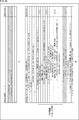
- the color difference sample position type identifier information chroma_sample_loc_type_idx is an identifier indicating a color difference sample position type (ChromaSampleLocType) determined for each color difference array type ChromaArrayType.
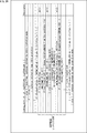
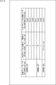
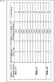
- FIG. 23 shows an example of a correspondence table of color difference array type ChromaArrayType and color difference sample position type ChromaSampelLocType associated with color difference sample position type identifier information chroma_sample_loc_type_idx.
- step S136 the decoding unit 111 sets the color difference sample position type ChromaSampleLocType based on the color difference array type ChromaArrayType and the color difference sample position type identifier information chroma_sample_loc_type_idx, for example, with reference to FIG.
- step S136 When the process of step S136 ends, the process proceeds to step S138. Further, in step S134, when it is determined that the above equation (19) is satisfied (when it is determined that the color difference array type ChromaArrayType is not CHROMA_420 and CHROMA_422), the process proceeds to step S137.
- step S137 the decoding unit 111 sets a predetermined type (DefaultType) without parsing the chrominance sample position type ChromaArrayType.
- DefaultType a predetermined type
- the predetermined type DefaultType is arbitrary, it is desirable that, for example, “Type 2” in which the positions of the luminance sample and the color difference sample coincide with each other.
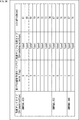
- step S138 the decoding unit 111 sets a chrominance intra prediction mode intraPredModeC based on the decoded inter-component prediction information CCInfo (ccp_flag, mclm_flag, ChromaSampleLocType) and the chrominance array type ChromaArrayType with reference to FIG.
- CCInfo ccp_flag, mclm_flag, ChromaSampleLocType
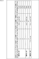
- the correspondence between the inter-component prediction information CCInfo and the chrominance array type ChromaArrayType to the chrominance intra prediction mode intraPredModeC is not limited to the example of FIG. For example, as in the example shown in FIG. 25, numbers may be assigned in order.
- step S138 ends, the decoding process ends, and the process returns to FIG.
- the intra-color difference intra prediction mode in the variable-length code decoding unit 21 and the decoding process related to inter-component prediction information have been described, these can change the processing order of each step or change the contents of the process within the feasible range. You may
- the decoding unit 111 decodes chrominance sample position information indicating the sample position of the chrominance component with respect to the luminance component sample as a part of the inter-component prediction information CCInfo.
- inter-Luma / Chroma prediction unit 141 it is possible to select a down sample filter that reduces the phase shift between the chrominance component and the luminance component based on the chrominance array type and the chrominance sample position information. Therefore, inter-component prediction with reduced phase shift is possible, and reduction in coding efficiency can be suppressed.
- chrominance sample position information chroma_sample_loc_info has been described with reference to FIG. 16, but the syntax of the chrominance sample position information chroma_sample_loc_info () is not limited to this example, and may be, for example, as shown in FIG. It may be of any configuration. That is, an initial value (default_chroma_sample_loc_type) may be provided in the chrominance sample position type, and chrominance sample position type identifier information chroma_sample_loc_type_idx may be transmitted only when the chrominance sample position type is other than the initial value.
- step S135 the decoding unit 111 decodes the following syntax included in the encoded data according to the definition of the syntax table shown in FIG.
- the decoding unit 111 parses and decodes the default chrominance sample position type flag default_chroma_sample_loc_type_flag included in the encoded data (obtains the default chrominance sample position type flag default_chroma_sample_loc_type_flag from the encoded data).
- the chrominance sample position type identifier information chroma_sample_loc_type_idx further included in the encoded data.
- the bin string bin is parsed and decoded (acquiring the bin string bin of chrominance sample position type identifier information chroma_sample_loc_type_idx from encoded data).
- the value of chrominance sample position type identifier information chroma_sample_loc_type_idx can be obtained by inverse binarizing the bin string.
- the default color difference sample position type flag default_chroma_sample_loc_type_flag is a flag indicating whether the color difference sample position type is the default type (initial value). For example, if this flag is "0", it indicates that the chrominance sample position type is not the default type. Also, for example, when this flag is “1”, it indicates that the color difference sample position type is the default type.
- the default chrominance sample location type may be Type 2.
- the color difference sample position type identifier information chroma_sample_loc_type_idx is an identifier indicating the color difference sample position type ChromaSampleLocType which is determined for each color difference array type ChromaArrayType excluding the default type.
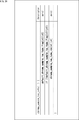
- FIG. 27 shows an example of a correspondence table of color difference sample position type ChromaSampelLocType associated with color difference array type ChromaArrayType, default color difference sample position type flag default_chroma_sample_loc_type_flag, and color difference sample position type identifier information chroma_sample_loc_type_idx.
- step S136 the decoding unit 111 sets the color difference sample position type ChromaSampleLocType based on the color difference array type ChromaArrayType, the default color difference sample position type flag default_chroma_sample_loc_type_flag, and the color difference sample position type identifier information chroma_sample_loc_type_idx, for example, referring to FIG. .
- chroma_sample_loc_type As shown in FIG. 26, a predetermined type (for example, Type 2) frequently used as color difference sample position type can be decoded / coded in one bin. . Therefore, the chrominance sample position information can be decoded / encoded with a smaller code amount than that of the syntax table shown in FIG. That is, it is possible to suppress the reduction of the coding efficiency.
- color difference sample positions in header information (VPS / SPS / PPS / SH / CTU) higher than the encoding unit may be decoded. That is, the chrominance sample position information chroma_sample_loc_info () may be stored in header information (VPS / SPS / PPS / SH / CTU) higher than the coding unit.
- inter-component linear prediction may be decoded in the header information of the coding unit as shown in B of FIG. That is, other syntax regarding inter-component linear prediction may be stored in header information of the coding unit.
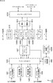
- FIG. 29 is a block diagram illustrating an exemplary main configuration of the prediction unit 114 of the image decoding device 100. As illustrated in FIG. 29, the prediction unit 114 includes an intra prediction unit 121 and an inter prediction unit 122.
- the intra prediction unit 121 performs processing related to intra prediction. For example, the intra prediction unit 121 acquires a decoded image as a reference image from the frame memory 116, and uses the decoded image to select the intra prediction mode specified by the prediction mode information Pinfo (ie, the optimum adopted on the encoding side). Intra prediction is performed in the prediction mode to generate a prediction image. The intra prediction unit 121 supplies the generated predicted image to the calculation unit 115.
- the prediction mode information Pinfo ie, the optimum adopted on the encoding side
- the inter prediction unit 122 performs processing related to inter prediction. For example, the inter prediction unit 122 acquires a decoded image as a reference image from the frame memory 116, and uses the decoded image to select the inter prediction mode specified by the prediction mode information Pinfo (that is, the optimum adopted on the encoding side). Inter prediction is performed in the prediction mode to generate a prediction image. The inter prediction unit 122 supplies the generated predicted image to the calculation unit 115.
- the prediction mode information Pinfo that is, the optimum adopted on the encoding side
- FIG. 30 is a block diagram illustrating an exemplary main configuration of the intra prediction unit 121.
- the intra prediction unit 121 includes a DC prediction unit 131, a Planar prediction unit 132, an Angular prediction unit 133, and a CC prediction unit 134.
- the DC prediction unit 131 performs processing related to DC prediction.
- the Planar prediction unit 132 performs a process related to Planar prediction.
- the Angular prediction unit 133 performs processing related to Angular prediction.
- the CC prediction unit 134 performs processing regarding inter-component linear prediction.
- the DC prediction unit 131 When the intra prediction mode predModeIntraX of the component X indicates DC prediction, the DC prediction unit 131 generates a DC predicted image with reference to the decoded image Rec X of the component X, and outputs it as a predicted image Pred X.
- the Planar prediction unit 132 When the intra prediction mode predModeIntraX of the component X indicates Planar prediction, the Planar prediction unit 132 generates a Planar predicted image with reference to the decoded image Rec X of the component X, and outputs it as a predicted image Pred X.
- the Angular prediction unit 133 When the intra prediction mode predModeIntraX of the component X indicates Angular prediction, the Angular prediction unit 133 generates an Angular prediction image with reference to the decoded image Rec X of the component X, and outputs it as a prediction image Pred X.
- the CC prediction unit 134 refers to the decoded image Rec X of the component X and the decoded image Rec z of the reference component Z to generate a CC predicted image (inter-component linear The predicted image is generated and output as a predicted image Pred X.
- FIG. 31 is a block diagram showing a main configuration example of the CC prediction unit 134.
- the CC prediction unit 134 includes the Luma / Chroma prediction unit 141 (also referred to as a brightness / color difference prediction unit), and the Cb / Cr residual prediction unit 142 (a color difference residual prediction unit Also referred to as
- the inter-Luma / Chroma prediction unit 141 performs processing on linear prediction between the luminance component and the chrominance component.
- the CC prediction unit 134 when correcting the predicted image Pred Cr of Cr component by Cb / Cr residual prediction, operates the Cb / Cr residual prediction unit 142 to correct the corrected Cr predicted image Pred * Generate Cb .
- the Cb / Cr residual prediction unit 142 performs processing regarding correction of a predicted image Pred Cr of a Cr component by Cb / Cr residual prediction.
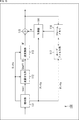
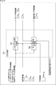
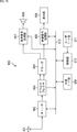
- FIG. 32 is a block diagram showing a main configuration example of the inter-Luma / Chroma prediction unit 141. As shown in FIG. As illustrated in FIG. 32, the inter-Luma / Chroma prediction unit 141 includes a reduced image generation unit 151, a prediction parameter derivation unit 152, and a color difference prediction image generation unit 153.
- the reduced image generation unit 151 performs processing regarding generation of a reduced image (that is, down-sampling).
- the prediction parameter derivation unit 152 performs processing regarding derivation of a prediction parameter (linear prediction parameter) used for linear prediction of a luminance component for generating a prediction image of a chrominance component.
- the color difference prediction image generation unit 153 performs processing regarding generation of a prediction image of a color difference component.
- the reduced image generation unit 151 includes a down sample filter selection unit 161, a luminance co-located block pixel group reduction unit 162, and a luminance co-located adjacent pixel group reduction unit 163.
- the down sample filter selection unit 161 performs processing regarding selection of the down sample filter. For example, the down sample filter selection unit 161 selects a down sample filter used for down sampling of the co-located block of the luminance component corresponding to the block to be processed of the chrominance component. Also, for example, the down sample filter selection unit 161 selects a down sample filter to be used for down sampling of the adjacent pixel group adjacent to the co-located block of the luminance component.
- the down sample filter selection unit 161 is based on information on the color format (for example, color difference array type ChromaArrayType) and information on the pixel position of the color difference component (for example, color difference sample position type (ChromaSampleLocType)) (that is, inter-component prediction information). Select the down sample filter of.
- the color format for example, color difference array type ChromaArrayType
- information on the pixel position of the color difference component for example, color difference sample position type (ChromaSampleLocType)
- ChromaSampleLocType color difference sample position type
- the down sample filter selection unit 161 corresponds to a plurality of color formats. That is, the down sample filter selection unit 161 selects a candidate corresponding to the color format of the format specified by the information on the color format and the information on the pixel position of the color difference component among the candidate group corresponding to the plurality of color formats. , Select as down sample filter.
- the candidate group may include a candidate corresponding to the color format of the 420 format and a candidate corresponding to the color format of the 422 format.
- the down sample filter selection unit 161 uses information on the pixel position of the color difference component among the candidates corresponding to the color format of the 420 format included in the candidate group. The corresponding candidate is selected as the down sample filter.
- the down sample filter selection unit 161 relates to the pixel position of the color difference component among the candidates corresponding to the color format of 422 format included in the candidate group.
- the candidate corresponding to the information is selected as the down sample filter.
- the candidate group may also include candidates corresponding to the 444 color format.
- the down sample filter selection unit 161 uses information on the pixel position of the color difference component among the candidates corresponding to the 444 format color format included in the candidate group. The corresponding candidate is selected as the down sample filter.
- the down sample filter selection unit 161 relates to linear prediction mode information (for example, multi-class linear prediction mode flag (mclm_flag)) which is information on a mode of linear prediction, information on the pixel position of the color difference component, and the color format. Down-sampling filters can also be selected based on the information.
- linear prediction mode information for example, multi-class linear prediction mode flag (mclm_flag)
- mclm_flag multi-class linear prediction mode flag
- the down sample filter selection unit 161 selects a mode specified by the linear prediction mode information, information on the pixel position of the color difference component, and information on the color format among the candidate groups corresponding to the plurality of modes of linear prediction.
- the candidate according to may be selected as the down sample filter.
- the candidate group may include the candidate corresponding to the single class mode and the candidate corresponding to the multi class mode.
- the single class mode is designated as the mode of linear prediction by the linear prediction mode information
- down sample filter selection section 161 relates to the pixel position of the chrominance component among the candidates corresponding to the linear prediction of the single class mode.
- the candidate corresponding to the information and the information on the color format is selected as the down sample filter.
- the multi-class mode is designated as the linear prediction mode by the linear prediction mode information
- the corresponding candidate is selected as the down sample filter.
- the down sample filter selection unit 161 supplies the selected down sample filter to the luminance co-located block pixel group reduction unit 162 and the luminance co-located adjacent pixel group reduction unit 163.
- the luminance co-located block pixel group reduction unit 162 performs processing relating to down-sampling of the co-located block of the luminance component corresponding to the block to be processed of the chrominance component. For example, the luminance co-located block pixel group reduction unit 162 obtains, from the frame memory 116, the co-located block of the luminance component corresponding to the block to be processed of the chrominance component. In addition, the luminance co-located block pixel group reduction unit 162 filters the acquired co-located block of the luminance component using the down-sample filter supplied from the down-sample filter selection unit 161 to generate a reduced image. The luminance co-located block pixel group reduction unit 162 supplies the generated reduced image of the co-located block of the luminance component to the color difference prediction image generation unit 153.
- the luminance co-located adjacent pixel group reduction unit 163 performs processing on down-sampling of the adjacent pixel group of the co-located block of the luminance component corresponding to the processing target block of the chrominance component. For example, the luminance colocated adjacent pixel group reduction unit 163 acquires, from the frame memory 116, the adjacent pixel group of the co-located block of the luminance component corresponding to the block to be processed of the chrominance component. In addition, the luminance colocate adjacent pixel group reduction unit 163 filters the adjacent pixel group of the acquired luminance component of the colocated block using the down sample filter supplied from the down sample filter selection unit 161, and reduces the reduced image. Generate The luminance co-located adjacent pixel group reduction unit 163 supplies the generated reduced image of the adjacent pixel group of the generated co-located block of the luminance component to the prediction parameter derivation unit 152.
- the luminance co-located block pixel group reduction unit 162 and the luminance co-located adjacent pixel group reduction unit 163 change the pixel position of the reference image of the luminance component using the filter selected by the down sample filter selection unit 161.
- the prediction parameter derivation unit 152 acquires, for example, the adjacent pixel group of the block to be processed of the chrominance component from the frame memory 116.
- the prediction parameter derivation unit 152 uses the adjacent pixel group of the block to be processed of the chrominance component and the reduced image of the adjacent pixel group of the colocated block of the luminance component supplied from the luminance colocated adjacent pixel group reduction unit 163. Derivate linear prediction parameters ( ⁇ , ⁇ ).
- the prediction parameter derivation unit 152 supplies the derived linear prediction parameters ( ⁇ , ⁇ ) to the color difference prediction image generation unit 153.
- the chrominance predicted image generation unit 153 uses the reduced image of the luminance co-located block supplied from the luminance co-located block pixel group reduction unit 162 and the linear prediction parameters ( ⁇ , ⁇ ) supplied from the prediction parameter derivation unit 152. Linear prediction is performed to generate a predicted image of the block to be processed of the chrominance component.
- the chrominance predicted image generation unit 153 selects a filter (for example, a down sample filter) selected based on information on pixel positions of chrominance components (for example, chrominance sample position information) and information on color format (for example, chrominance array type).
- the pixel value of the chrominance component eg, Cb component and Cr component
- the color difference prediction image generation unit 153 supplies the generated prediction image to the calculation unit 115.
- step S151 the prediction unit 114 determines whether to perform intra prediction. If intra prediction is specified by the prediction mode information Pinfo and it is determined that intra prediction will generate a predicted image of a block to be processed of a chrominance component, the process proceeds to step S152.
- step S152 the intra prediction unit 121 performs intra prediction to generate a predicted image.
- the prediction process ends, and the process returns to FIG.
- step S151 in FIG. 33 when inter prediction is designated by the prediction mode information Pinfo and it is determined that intra prediction is not performed, the processing proceeds to step S153.
- step S153 the inter prediction unit 122 performs inter prediction to generate a predicted image.
- the prediction process ends, and the process returns to FIG.
- the DC prediction unit 131, the Planar prediction unit 132, the Angular prediction unit 133, and the CC prediction unit 134 of the intra prediction unit 121 perform intra processing in a mode according to predModeIntraX for each component in step S161. Make predictions and generate predicted images. For example, when CC prediction is specified in predModeIntraX, the CC prediction unit 134 generates a prediction image of a chrominance component by inter-component linear prediction.
- step S161 ends, the intra prediction process ends, and the process returns to FIG.
- step S171 the inter-Luma / Chroma prediction unit 141 performs inter-luminance-color difference prediction processing to predict a predicted image of a chrominance component from a decoded image of a luminance component.
- step S172 the Cb / Cr residual prediction unit 142 performs inter-color difference residual prediction processing, and corrects the predicted image of the Cr component using the prediction residual of the Cb component.
- step S172 ends, the inter-component linear prediction process ends, and the process returns to FIG.
- step S181 the prediction parameter derivation unit 152 sets the adjacent decoded pixel group R C, n of the prediction target block of the color difference component (Cb component) (A in FIG.
- the color difference adjacent pixel group R C, n is read from the frame memory 116.
- step S 182 the reduced image generation unit 151 calls the decoded pixel group R Y, col of the luminance component at the co-located position of the color difference prediction target block (B in FIG. 2) (hereinafter referred to as luminance co-located block pixel group R Y, col And the adjacent decoded pixel group R Y, n (hereinafter referred to as luminance colocated adjacent pixel group R Y, n ) of the luminance component at the co-located position of the chrominance adjacent pixel group R c, n from the frame memory 116 .
- luminance co-located block pixel group R Y col
- the adjacent decoded pixel group R Y, n hereinafter referred to as luminance colocated adjacent pixel group R Y, n
- the luminance co-located block pixel group reduction unit 162 obtains the luminance co-located block pixel group R Y, n from the frame memory 116.
- the luminance co-located adjacent pixel group reduction unit 163 acquires the luminance co-located adjacent pixel group R Y, n from the frame memory 116.
- step S183 the down sample filter selection unit 161 selects a down sample filter determined in a one-to-one correspondence with the color difference array type ChromaArray Type and the color difference sample position type Chroma Sample Loc Type, for example, as shown in the table in FIG.
- the down sample filter selection unit 161 selects a down sample filter that generates a luminance sample having the same coordinates as the color difference sample position, based on the color difference array type ChromaArrayType and the color difference sample position type ChromaSampleLocType.
- (2x, 2y) and its four neighbors ((2x, 2y-2), (2x-2, 2y), (2x + 2, 2y), (2x, 2y + 2)
- the filter coefficients corresponding to each luminance sample position are as shown in FIG. 39, for example.
- the filter coefficients corresponding to each luminance sample position are, for example, as shown in FIG.
- select a down-sample filter that generates a luminance sample having the same coordinates as the chrominance sample (target chrominance sample) at the (2x, 2y + 1) position.
- select a down-sampling filter that references luminance samples at positions (2x, 2y) and (2x, 2y + 2).
- the filter coefficients corresponding to each luminance sample position are, for example, as shown in FIG.
- a down sample filter is selected that generates a luminance sample having the same coordinates as the chrominance sample (target chrominance sample) at the (2x + 1, 2y + 1) position. See, for example, luminance samples at positions (2x, 2y), (2x + 2, 2y), (2x, 2y + 2), (2x + 2, 2y + 2) as shown in FIG.
- Select the down sample filter you want to The filter coefficients corresponding to each luminance sample position are, for example, as shown in FIG.
- a filter is selected which generates a luminance sample having the same coordinates as the chrominance sample (target chrominance sample) at the (2x, 2y) position.
- a filter is selected which refers to luminance samples located at (2x, 2y) and left and right (2x-2, 2y), (2x + 2, 2y).
- the filter coefficients corresponding to each luminance sample position are, for example, as shown in FIG.
- a down sample filter is selected that generates a luminance sample having the same coordinates as the chrominance sample (target chrominance sample) at the (2x + 1, 2y) position.
- select a down-sampling filter that refers to luminance samples located at (2x, 2y) and (2x + 2, 2y).
- the filter coefficients corresponding to each luminance sample position are, for example, as shown in FIG.
- the filter coefficients corresponding to each luminance sample position are, for example, as shown in FIG.
- the down sample filter that generates a luminance sample having the same coordinates as the chrominance sample position is optional, and is not limited to the above-described example.
- the number of reference samples may be increased or decreased.
- the value of the filter coefficient can be changed within the feasible range.
- the down-sampling filter may be a separable filter or a non-separable filter.
- an arbitrary filter such as, for example, a linear interpolation filter, a bicubic filter, or a Lanczos filter (a Lanczos filter) may be applied.
- the luminance corocate adjacent pixel group reduction unit 163 applies the selected down sample filter to the luminance corocate adjacent pixel group R Y, n to reduce the luminance colocated adjacent pixel group R. 'Generate Y, n .
- the luminance co-located adjacent pixel group reducing unit 163 supplies the reduced luminance co-located adjacent pixel group R′Y , n to the prediction parameter deriving unit 152.
- step S185 the brightness co-located block pixel group reduction unit 162, the brightness co-located block pixel group R Y, to col, by applying the downsampling filters selected, reduced luminance co-located block pixel group R 'Y, to generate the col .
- the luminance co-located block pixel group reduction unit 162 supplies the reduced luminance co-located block pixel group R′Y , col to the color difference prediction image generation unit 153.
- step S186 the prediction parameter derivation unit 152 generates a linear for each class i used for inter-Luma / Chroma prediction based on the supplied reduced luminance co-located adjacent pixel group R ′ Y, n and chrominance adjacent pixel group R C, n.
- the prediction parameters ( ⁇ i , ⁇ i ) are derived.
- the prediction parameter derivation unit 152 derives prediction parameters for the corresponding number of classes with reference to inter-component prediction information (of the multiclass linear prediction mode flag mclm_flag).
- the prediction parameter derivation unit 152 predicts the prediction parameter ⁇ 1 (equation (equation (equation (2)).
- the scaling term ⁇ ) in 1) and the prediction parameter ⁇ 1 (offset term ⁇ in equation (1)) are derived.
- the prediction parameter deriving unit 152 determines each reduced luminance co-located adjacent pixel group R 'Determine the threshold value Thr from Y, n .
- the determination method of this threshold value Thr is arbitrary. For example, it may be an average value.
- the prediction parameter derivation unit 152 for each class j, reduced luminance collocated adjacent pixel groups R belonging to each class j 'Y, n, j, reduced luminance collocated adjacent pixel groups R' Y, n, by referring to the j
- the prediction parameters ⁇ j and ⁇ j are derived according to equation (2).
- the number of classes is not limited to two, and three or more classes may be assumed to derive prediction parameters for each class.
- the K-means method may be used as a classification method.
- the color difference prediction image generation unit 153 refers to the prediction parameter ( ⁇ j , ⁇ j ) for each class j derived as described above to reduce the luminance co-located block pixel group
- the color difference prediction image Pred C is generated from R′Y , col .
- the color difference prediction image generation unit 153 refers to the prediction parameters ( ⁇ 1 , ⁇ 1 ) to perform the equation (( 1 )
- the color difference prediction image Pred C is generated based on 1).
- the color difference prediction image generation unit 153 derives from the prediction parameter derivation unit 152.
- the color difference prediction image Pred C is generated based on the equation (5) with reference to the threshold value Thr and the prediction parameters ( ⁇ j , ⁇ j ) of each class j.
- the color difference prediction image generation unit 153 classifies it as class 1 and selects prediction parameters ( ⁇ By performing linear prediction using 1 , 1 , ⁇ 1 ), the predicted value Pred C [x, y] of the color difference component of the same coordinate is derived.
- the color difference prediction image generation unit 153 classifies it as class 2 and sets prediction parameters corresponding to class 2 ( By performing linear prediction using ⁇ 2 , ⁇ 2 ), the predicted value Pred C [x, y] of the color difference component of the same coordinate is derived.
- step S187 when the process of step S187 ends, the process returns to FIG.
- the inter-Luma / Chroma prediction unit 141 can derive the predicted image Pred C of the color difference component. As described above, the inter-Luma / Chroma prediction unit 141 generates a luminance sample having the same coordinates as the chrominance sample position based on the chrominance array type and the chrominance sample position information in both the single class mode and the multiple class mode. By selecting the down-sampling filter, it is possible to generate a reduced luminance co-located adjacent pixel group R ′ Y, n in which the phase shift from the luminance co-located adjacent pixel group R Y, n to the color difference component is reduced. Therefore, since the phase shift is small, more accurate prediction parameters ( ⁇ , ⁇ ) can be derived. Therefore, a reduction in coding efficiency can be suppressed.
- the Luma / Chroma prediction unit 141 is a down sample filter that generates a luminance sample having the same coordinates as the chrominance sample position based on the chrominance array type and the chrominance sample position information in both the single class mode and the multiple class mode. the by selecting the luminance co-located block pixel group R Y, reduced luminance was reduced phase shift between the color difference components from the col co-located block pixel group R 'Y, can generate col.
- the color difference format is not limited to the 420 format, and Luma / Chroma prediction corresponding to the 422 format and 444 format can be performed. That is, since Luma / Chroma prediction can be applied in the 422 format and the 444 format, coding efficiency is improved.
- the CC prediction unit 134 includes the Cb / Cr residual prediction unit 142.
- FIG. 52 is a block diagram showing a main configuration example of the Cb / Cr residual prediction unit 142. As shown in FIG.
- the Cb / Cr residual prediction unit 142 includes a residual prediction parameter derivation unit 171 and a color difference prediction image correction unit 172.
- the residual prediction parameter derivation unit 171 performs processing on derivation of a residual prediction parameter which is a parameter used for inter-color difference residual prediction (Cr / Cb residual prediction) performed for correcting a predicted image of a Cr component. Do.
- the color difference predicted image correction unit 172 performs processing regarding correction of the predicted image of the Cr component.
- the color difference prediction image correction unit 172 generates the prediction image of the Cr component generated by the color difference prediction image generation unit 153 as the prediction residual of the collocated block of the Cb component corresponding to the prediction image of the (current CU) Cr component. Use to correct.
- the residual prediction parameter derivation unit 171 is a parameter used for correcting the predicted image of the Cr component based on the adjacent pixels adjacent to the predicted image of the Cr component and the adjacent pixels adjacent to the co-located block of the Cb component. Deriving certain residual prediction parameters.
- the chrominance predicted image correction unit 172 performs chrominance residual prediction using the derived residual prediction parameter, and corrects a predicted image of a Cr component.
- the Cb / Cr residual prediction unit 142 When the inter-color difference residual prediction process is started, the Cb / Cr residual prediction unit 142 generates the predicted image P Cr of the prediction target block of the Cr component generated by the inter-Luma / Chroma prediction unit 141 in step S201.
- the Cr predicted image PCr and the adjacent decoded pixel group RCr, n (hereinafter, referred to as Cr adjacent pixel group RCr, n ) stored in the frame memory 116 are read.
- the Cb / Cr residual prediction unit 142 supplies the Cr adjacent pixel group RCr, n to the residual prediction parameter derivation unit 171. Further, the Cb / Cr residual prediction unit 142 supplies the Cr prediction image PCr to the color difference prediction image correction unit 172.
- step S202 the Cb / Cr residual prediction unit 142 calculates the adjacent decoded pixel group RCb , n of the Cb component at the co-located position of the Cr adjacent pixel group RCr , n (hereinafter referred to as Cb colocated adjacent pixel group RCb, n ) are read from the frame memory 116.
- the Cb / Cr residual prediction unit 142 supplies the Cb-colocated adjacent pixel group RCb, n to the residual prediction parameter derivation unit 171.
- step S203 the Cb / Cr residual prediction unit 142 inversely quantizes and inversely transforms the prediction target block of the Cr component (Cr predicted image P Cr ) and the transform coefficient Coeff of the co-located block of the Cb component at the co-located position.
- the prediction residual Resi (hereinafter referred to as Cb co-located prediction residual Resi Cb ) obtained as a result is read.
- the Cb / Cr residual prediction unit 142 supplies the Cb co-located prediction residual Resi Cb to the color difference prediction image correction unit 172.
- step S204 the residual prediction parameter derivation unit 171 uses the residual Cr for Cb / Cr residual prediction based on the supplied Cr adjacent pixel R Rc, n and the Cb-correlated adjacent R Rc b, n. Derivation of difference prediction parameter ⁇ .
- the residual prediction parameter derivation unit 171 derives a residual prediction parameter ⁇ (a scaling term ⁇ in the above-mentioned Expression (10)) based on the above-mentioned Expression (11).
- step S205 the chrominance predicted image correction unit 172 performs residual prediction using the residual prediction parameter ⁇ and the supplied Cb co-located prediction residual Resi Cb to correct the Cr predicted image PCr .
- the color difference prediction image correction unit 172 based on equation (10) described above, the Cb collocated prediction residual Resi Cb to alpha ⁇ Resi Cb multiplied by the prediction parameters alpha and Cr predicted image P Cr Add to generate a corrected Cr predicted image P * Cr .
- the Cb / Cr residual prediction unit 142 can correct the predicted image Pred Cr of the Cr component.
- step S221 the decoding unit 111 parses and acquires syntax groups related to a decoding target CU (also referred to as a current CU) from encoded data.
- a decoding target CU also referred to as a current CU
- step S222 the prediction unit 114 generates a predicted image of the luminance component.
- step S223 the inverse quantization unit 112 and the inverse transformation unit 113 perform inverse quantization and inverse transformation, and the transformation coefficients after quantization of the luminance component of the current CU obtained by decoding the encoded data by the decoding unit 111 Convert to a prediction residual.
- step S224 the operation unit 115 decodes the luminance component of the current CU using the prediction residual of the luminance component obtained by the process of step S223 and the predicted image of the luminance component obtained by the process of step S222. Restore the image.
- step S225 the prediction unit 114 performs inter-component linear prediction processing, and generates, for the current CU, a predicted image of a chrominance component (Cb) from the decoded image of the luminance component obtained by the processing of step S224.
- Cb chrominance component
- step S226 the inverse quantization unit 112 and the inverse conversion unit 113 perform inverse quantization and inverse conversion, and after quantization of the chrominance component (Cb) of the current CU obtained by decoding the encoded data by the decoding unit 111 Convert the transform coefficients of to prediction residuals.
- Cb chrominance component
- step S227 the operation unit 115 uses the prediction residual of the color difference component (Cb) obtained by the process of step S226 and the predicted image of the color difference component (Cb) obtained by the process of step S225. Restore the decoded image of the color difference component (Cb) of the CU.
- step S228, the prediction unit 114 performs inter-component linear prediction processing, and generates, for the current CU, a predicted image of a chrominance component (Cr) from the decoded image of the luminance component obtained by the processing of step S224.
- Cr chrominance component
- step S229 the prediction unit 114 performs inter-color difference residual prediction (Cb / Cr inter-residue prediction), and using the prediction residual of the color difference component (Cb), the current CU obtained by the process of step S228. Correct the predicted image of the chrominance component (Cr).
- step S230 the inverse quantization unit 112 and the inverse conversion unit 113 perform inverse quantization and inverse conversion, and after quantization of the chrominance component (Cr) of the current CU obtained by decoding the encoded data by the decoding unit 111 Convert the transform coefficients of to prediction residuals.
- Cr chrominance component
- step S231 the operation unit 115 uses the prediction residual of the chrominance component (Cr) obtained by the processing of step S229 and the predicted image after the correction of the chrominance component (Cr) obtained by the processing of step S230. Then, the decoded image of the chrominance component (Cr) of the current CU is restored.
- step S231 When the process of step S231 ends, the CU level decoding process ends.
- the image decoding apparatus 100 can obtain a decoded image of each CU using the inter-component linear prediction process and the inter-color difference residual prediction.
- the image decoding apparatus 100 which is an embodiment of the image processing apparatus to which the present technology is applied, uses the filter selected based on the information on the pixel position of the color difference component and the information on the color format. Based on the pixel value of the reference image of the luminance component whose position has been changed, the pixel value of the color difference component is predicted by linear prediction, and a prediction unit that generates a prediction image of the color difference component and the prediction image generated by the prediction unit And a decoding unit that decodes chrominance components of encoded data in which an image is encoded.
- the image decoding apparatus 100 performs linear prediction from the pixel value of the reference image of the luminance component whose pixel position has been changed using the filter selected based on the information on the pixel position of the chrominance component and the information on the color format.
- the pixel values of the chrominance components are predicted, a prediction image of the chrominance components is generated, and the generated prediction image is used to decode the chrominance components of the encoded data in which the image is encoded.
- the image decoding apparatus 100 can suppress the reduction in the coding efficiency.
- FIG. 55 is a block diagram illustrating an example of a configuration of an image coding device which is an aspect of an image processing device to which the present technology is applied.
- the image coding apparatus 200 shown in FIG. 55 is an image coding apparatus corresponding to the image decoding apparatus 100 in FIG. 15, and the image decoding apparatus 100 receives coded data (bit stream) decoded by the image decoding apparatus 100.
- the image is generated by encoding the image according to the encoding method corresponding to the decoding method according to.
- the image coding apparatus 200 implements the technology proposed for HEVC and the technology proposed for JVET.
- FIG. 55 shows main processing units, data flows, etc., and the one shown in FIG. 55 is not limited to all. That is, in the image coding apparatus 200, there may be a processing unit not shown as a block in FIG. 55, or there may be processing or data flow not shown as an arrow or the like in FIG.
- the image coding apparatus 200 includes a control unit 201, a prediction unit 211, an operation unit 212, a conversion unit 213, a quantization unit 214, an inverse quantization unit 215, an inverse conversion unit 216, an operation unit 217, A frame memory 218, a loop filter unit 219, and an encoding unit 220 are included.
- the control unit 201 divides the moving image # 2 into processing unit blocks (CU, PU, conversion block, etc.) based on a block size of a processing unit specified externally or in advance, and corresponds to the divided blocks.
- the image I is input to the calculation unit 212.
- the control unit 201 determines coding parameters (header information Hinfo, prediction mode information Pinfo, conversion information Tinfo, filter information Finfo, etc.) to be supplied to each block based on, for example, RDO (Rate-Distortion Optimization). .
- the determined coding parameters are supplied to each block. Specifically, it is as follows.
- the header information Hinfo is supplied to each block.
- the prediction mode information Pinfo is supplied to the coding unit 220 and the prediction unit 211.
- the transform information Tinfo is supplied to the coding unit 220, the transform unit 213, the quantization unit 214, the inverse quantization unit 215, and the inverse transform unit 216.
- the filter information Finfo is supplied to the loop filter unit 219.
- the prediction unit 211 performs processing related to generation of a predicted image. For example, the prediction unit 211 receives the prediction mode information Pinfo supplied from the control unit 201, and stores in the frame memory 218 specified by the prediction mode information Pinfo by the prediction method specified by the prediction mode information Pinfo. The predicted image P is generated using the decoded image R ′ after the filtering (or the decoded image R before the filter) as a reference image, and is output to the calculation unit 212.
- the operation unit 212 receives the image I corresponding to the block of the processing unit and the predicted image P supplied from the prediction unit 211, and subtracts the predicted image P from the image I as shown in the following equation (20) Then, the prediction residual D is derived and output to the transformation unit 213.
- the transformation unit 213 is an inverse process of the inverse transformation unit 113, receives the prediction residual D and the transformation information Tinfo, applies a transformation to the prediction residual D based on the transformation information Tinfo, and converts the transformation coefficient Coeff. Are derived and output to the quantization unit 214.
- the quantization unit 214 is inverse processing of the inverse quantization unit 112, receives the conversion information Tinfo and the conversion coefficient Coeff, scales (quantizes) the conversion coefficient Coeff based on the conversion information Tinfo, and performs quantization after quantization.
- the transform coefficient that is, the quantized transform coefficient level level is output to the encoding unit 220.
- the inverse quantization unit 215 has the same configuration as the inverse quantization unit 112, and performs the same processing. That is, the inverse quantization unit 215 performs inverse processing of the quantization unit 214.
- the inverse transform unit 216 has the same configuration as the inverse transform unit 113, and performs the same processing. That is, the inverse conversion unit 216 performs the reverse process to the conversion unit 213.
- the operation unit 217 adds the prediction residual D ′ and the prediction image P corresponding to the prediction residual D ′ to derive a locally decoded image R local .
- the frame memory 218 performs processing related to storage of data related to an image. For example, the frame memory 218 receives the locally decoded image R local supplied from the operation unit 217, reconstructs the decoded image R for each picture unit, and stores the reconstructed image R in a buffer in the frame memory 218. The frame memory 218 reads the decoded image R from the buffer and supplies the read image R to the loop filter unit 219.
- the loop filter unit 219 performs processing related to loop filter processing. For example, the loop filter unit 219 reads the decoded image R from the frame memory 218, and generates a decoded image R ′ after filtering by loop filter processing specified by the filter information Finfo. Also, the loop filter unit 219 supplies the decoded image R ′ after filtering to the frame memory 218.
- the loop filter processing performed by the loop filter unit 219 includes a deblocking filter (DBF (DeBlocking Filter)), a pixel adaptive offset (SAO (Sample Adaptive Offset)), and an adaptive loop filter (ALF (Adaptive Loop Filter)). And other linear and non-linear filters (such as Wiener filters, bilateral filters, etc.).
- the encoding unit 220 performs encoding that is the reverse process of the decoding performed by the decoding unit 111.
- the encoding unit 220 uses the encoding parameters (header information, prediction mode information Pinfo, conversion information Tinfo, filter information Finfo, etc.) supplied from the control unit 201 according to the definition of the syntax table, and
- the quantization transformation coefficient level level supplied from the encoding unit 214 is converted into a syntax value of each syntax element, each syntax value is subjected to variable length coding (for example, arithmetic coding), and a bit string (coded data Generate).
- the encoding unit 220 derives residual information Rinfo from the quantized transform coefficient level level, encodes the residual information Rinfo, and generates a bit string. Also, the encoding unit 220 multiplexes the bit string of each syntax element that has been subjected to variable-length encoding, and generates and outputs encoded data # 1.
- the arithmetic unit 212 to the quantization unit 214 and the encoding unit 220 operate as an encoding unit that encodes the chrominance components of the image using the predicted image generated by the prediction unit 211.
- the image coding apparatus 200 performs, for example, a process related to image coding by executing the image coding process.
- step S241 the control unit 201 performs coding control process, and performs block division, setting of coding parameters, and the like.
- step S242 the prediction unit 211 performs prediction processing to generate a predicted image or the like in an optimal prediction mode.
- step S243 the computing unit 212 computes the difference between the input image and the predicted image of the optimal mode selected by the prediction process of step S242. That is, the calculation unit 212 generates a prediction residual D between the input image and the prediction image.
- the prediction residual D obtained in this manner has a reduced amount of data compared to the original image data. Therefore, the amount of data can be compressed as compared to the case of encoding the image as it is.
- step S244 the converting unit 213 performs a conversion process on the prediction residual D generated by the process of step S243, and derives a conversion coefficient Coeff. Note that this conversion process is an inverse process of the inverse conversion process of step S103, and is an inverse process of the inverse conversion process performed in the above-described image decoding process.
- step S245 the quantization unit 214 quantizes the transform coefficient Coeff obtained by the process of step S244 using, for example, the quantization parameter calculated by the control unit 201, and derives a quantized transform coefficient level level. .
- step S246 the inverse quantization unit 215 inversely quantizes the quantized transformation coefficient level level generated by the process of step S245 with the characteristic corresponding to the characteristic of the quantization, and derives the transformation coefficient Coeff_IQ.
- step S247 the inverse transform unit 216 inversely transforms the transform coefficient Coeff_IQ obtained by the process of step S246 by a method corresponding to the transform process of step S244 to derive a prediction residual D '.
- the inverse conversion process is performed in the same manner as the inverse conversion process performed in the above-described image decoding process.
- step S248 the operation unit 217 adds the predicted image obtained by the prediction process of step S242 to the prediction residual D ′ derived by the process of step S247, thereby generating a locally decoded image.
- step S249 the frame memory 218 stores the locally decoded decoded image obtained by the process of step S248.
- step S250 the encoding unit 220 encodes the quantized transform coefficient level level obtained by the process of step S245.
- the encoding unit 220 encodes the quantization conversion coefficient level level, which is information about an image, by arithmetic coding or the like to generate encoded data.
- the encoding unit 220 encodes various encoding parameters (header information Hinfo, prediction mode information Pinfo, conversion information Tinfo).
- the encoding unit 220 derives residual information Rinfo from the quantized transform coefficient level level, and encodes the residual information Rinfo.
- step S251 the loop filter unit 219 performs predetermined filter processing on the local decoded image stored in the frame memory 218.
- the image encoding process ends. Note that, in step S251, the locally decoded image after filtering is stored in the frame memory 218.
- step S251 When the process of step S251 ends, the image encoding process ends.
- FIG. 20 is an example of a syntax table of coding_unit () corresponding to the flowcharts of FIGS. 57 and 58.
- step S261 the encoding unit 220 encodes the inter-component prediction enabled flag ccp_enabled_flag according to the control of the control unit 201, and adds it to the encoded data.
- step S261 the encoding unit 220 determines whether condition 1 shown in the above equation (13) is satisfied. That is, the encoding unit 220 determines whether the inter-component prediction enabled flag ccp_enabled_flag is 1 (true). If it is determined that the above equation (13) is satisfied (if it is determined that the ccp_enabled_flag is 1 (true)), the processing proceeds to step S263.
- step S263 the encoding unit 220 encodes the inter-component prediction flag ccp_flag according to the control of the control unit 201, and adds it to the encoded data.
- step S263 ends, the process proceeds to step S264. If it is determined in step S262 that the above equation (13) is not satisfied (if it is determined that ccp_enabled_flag is 0 (false)), the process of step S263 is skipped (omitted), and the process is performed Go to S264.
- step S264 the encoding unit 220 determines whether condition 2 shown in the above equation (14) is satisfied. That is, the encoding unit 220 determines whether the inter-component prediction flag ccp_flag is 0 (false). If it is determined that the above equation (14) is satisfied (if it is determined that the ccp_flag is 0 (false)), the processing proceeds to step S265.
- the above equation (14) may be changed to another determination equation as long as an equivalent result is obtained.
- the above equation (15) may be substituted.
- step S265 the encoding unit 220 encodes the chrominance MPM identifier chroma_mpm_idx and adds it to the encoded data.
- the encoding process ends, and the process returns to FIG.
- step S 264 in FIG. 57 If it is determined in step S 264 in FIG. 57 that the above equation (14) is not satisfied (if it is determined that ccp_flag is 1 (true)), the process proceeds to FIG.
- step S271 of FIG. 58 the encoding unit 220 determines whether condition 3 shown in the above equation (17) is satisfied. That is, the encoding unit 220 determines whether the size (widthC * heightC) of the color difference encoding block is equal to or larger than the MCLM minimum block size MCLMMinBlkSize and equal to or smaller than the MCLM maximum block size MCLMMaxBlkSize.
- the portion for comparing the size of the chrominance block and the threshold may be replaced by the logarithmic expression shown in the above equation (18).
- step S272 the encoding unit 220 encodes the multi-class linear prediction mode flag mclm_flag and adds it to the encoded data.
- step S273 the process proceeds to step S273.
- the size of the chrominance encoding block (widthC * heightC) is smaller than MCLM minimum block size MCLMMinBlkSize, or larger than MCLM maximum block size MCLMMaxBlkSize (When it is determined) that the process of step S272 is skipped, the process proceeds to step S273.
- step S273 the encoding unit 220 determines whether the condition 4 shown in the above equation (19) is satisfied, that is, whether the color difference array type ChromaArrayType is CHROMA_420 or CHROMA_422.
- step S274 the encoding unit 220 encodes the chrominance sample position information chroma_sample_loc_info () according to the definition of the syntax table according to the control of the control unit 201, and includes the encoded data in the encoded data.
- the encoding unit 220 encodes the bin string bin of the chrominance sample position type identifier information chroma_sample_loc_type_idx according to the definition of the syntax table shown in FIG.
- the bin sequence is obtained by binarizing the chrominance sample position type identifier information chroma_sample_loc_type_idx.
- step S274 ends, the process returns to FIG. 57, the encoding process ends, and the process returns to FIG.
- step S273 of FIG. 58 If it is determined in step S273 of FIG. 58 that equation (19) is not satisfied (if it is determined that the color difference array type ChromaArrayType is neither CHROMA_420 nor CHROMA_422), the process of step S274 is skipped. The process returns to FIG. 57, the encoding process ends, and the process returns to FIG.
- the encoding unit 220 encodes, as a part of the inter-component prediction information CCInfo, chrominance sample position information chroma_sample_loc_info () indicating the sample position of the chrominance component with respect to the luminance component sample. Therefore, in the Luma / Chroma inter prediction unit 141 (intra prediction unit 231), a down sample filter that reduces the phase shift between the chrominance component and the luminance component based on the chrominance array type ChromaArrayType and chrominance sample position information chroma_sample_loc_info (). It becomes selectable. Therefore, the image coding apparatus 200 can perform inter-component prediction with reduced phase shift, and can suppress reduction in coding efficiency.
- chrominance sample position information chroma_sample_loc_info indicating the sample position of the chrominance component with respect to the luminance component sample. Therefore, in the Luma / Chroma inter prediction unit 141 (intra prediction unit 231), a
- chrominance sample position information chroma_sample_loc_info has been described with reference to FIG. 16, but the syntax of the chrominance sample position information chroma_sample_loc_info () is not limited to this example, and may be, for example, as shown in FIG. It may be of any configuration. That is, an initial value (default_chroma_sample_loc_type) may be provided in the chrominance sample position type, and chrominance sample position type identifier information chroma_sample_loc_type_idx may be transmitted only when the chrominance sample position type is other than the initial value.
- step S274 the encoding unit 220 encodes the following syntax in accordance with the definition of the syntax table shown in FIG.
- the encoding unit 220 encodes the default chrominance sample position type flag default_chroma_sample_loc_type_flag. If the flag is false (0), the encoding unit 220 further encodes the bin string bin of the chrominance sample position type identifier information chroma_sample_loc_type_idx. This bin string can be obtained by binarizing the value of the chrominance sample position type identifier information chroma_sample_loc_type_idx.
- chrominance sample position information chroma_sample_loc_type () based on the definition of the syntax table in FIG. 26, it is possible to encode a predetermined type (for example, Type 2) that is frequently used as the chrominance sample position type in one bin. Therefore, chrominance sample position information can be encoded with a smaller amount of code than in the case of FIG. That is, it is possible to suppress the reduction of the coding efficiency.
- color difference sample positions in header information (VPS / SPS / PPS / SH / CTU) higher than the encoding unit may be encoded. That is, the chrominance sample position information chroma_sample_loc_info () may be stored in header information (VPS / SPS / PPS / SH / CTU) above the encoding unit.
- inter-component linear prediction may be encoded in header information of the encoding unit as shown in B of FIG. That is, other syntax regarding inter-component linear prediction may be stored in header information of the coding unit.
- FIG. 59 is a block diagram illustrating an exemplary main configuration of the prediction unit 211 of the image coding device 200. As illustrated in FIG. 59, the prediction unit 211 includes an intra prediction unit 231, an inter prediction unit 232, and a predicted image selection unit 233.
- the intra prediction unit 231 performs processing related to intra prediction. For example, the intra prediction unit 231 acquires a decoded image as a reference image from the frame memory 218, performs intra prediction based on the prediction mode information Pinfo using the decoded image, and generates a predicted image. The intra prediction unit 231 performs intra prediction in each intra prediction mode, and calculates each cost function (also referred to as a cost). The intra prediction unit 231 supplies the generated prediction image of each intra prediction mode to the prediction image selection unit 233 together with prediction mode information Pinfo and the like.
- the inter prediction unit 232 performs processing related to inter prediction. For example, the inter prediction unit 232 acquires a decoded image as a reference image from the frame memory 116, performs inter prediction based on the prediction mode information Pinfo using the decoded image, and generates a prediction image. The inter prediction unit 232 performs inter prediction in each inter prediction mode, and calculates each cost function. The inter prediction unit 232 supplies the generated prediction image of each inter prediction mode to the prediction image selection unit 233 together with prediction mode information Pinfo and the like.
- the prediction image selection unit 233 selects, from among the intra prediction image supplied from the intra prediction unit 231 and the inter prediction image supplied from the inter prediction unit 232, a prediction image of an optimum prediction mode based on, for example, a cost function. Choose The prediction image selection unit 233 supplies the selected prediction image to the calculation unit 212 and the calculation unit 217.
- step S291 the intra prediction unit 231 performs intra prediction to generate a prediction image.
- step S291 the process proceeds to step S292.
- step S292 the inter prediction unit 232 performs inter prediction to generate a prediction image.
- the process of step S292 ends, the process proceeds to step S293.
- step S293 the intra prediction unit 231 calculates a cost function of each intra prediction mode, the inter prediction unit 232 calculates a cost function of each inter prediction mode, and the prediction image selection unit 233 generates a cost function of those inter prediction modes. Based on the (predicted image of) the optimal prediction mode is selected.
- step S293 ends, the prediction process ends, and the process returns to FIG.
- the prediction unit 211 can code a prediction image of the optimum prediction mode. Therefore, a reduction in coding efficiency can be suppressed.
- the intra prediction unit 231 has basically the same configuration as the intra prediction unit 121 of the image decoding apparatus 100, and performs the same intra prediction. That is, the description of the intra prediction unit 121 described above in the first embodiment can be basically applied to the intra prediction unit 231.
- the intra prediction unit 231 has a configuration as shown in FIG. That is, the intra prediction unit 231 also includes the DC prediction unit 131 to the CC prediction unit 134.
- the intra prediction unit 231 performs intra prediction in all prediction modes as described above. Also, parameters used for CC prediction, such as prediction mode information Pinfo, are not extracted from the encoded data, but, for example, from other processing units of the image coding device 200, such as the control unit 201 and the coding unit 220. Provided.
- the DC prediction unit 131 When the intra prediction process is started, the DC prediction unit 131 performs DC prediction in step S301 to generate a predicted image.
- the Planar prediction unit 132 performs Planar prediction to generate a predicted image.
- the Angular prediction unit 133 performs Angular prediction to generate a predicted image.
- the CC prediction unit 134 performs CC prediction (inter-component prediction processing) to generate a predicted image.
- step S304 ends, the intra prediction process ends, and the process returns to FIG.
- the intra prediction unit 231 generates a prediction image in each prediction mode. Therefore, the prediction unit 211 can select the prediction image of the optimal mode. That is, it is possible to suppress the reduction of the coding efficiency.
- the CC prediction unit 134 basically has the same configuration as that of the first embodiment, and performs the same processing. That is, the description of the CC prediction unit 134 described above in the first embodiment can be basically applied to this case as well.
- the CC prediction unit 134 has a configuration as shown in FIG. 30, and executes inter-component linear prediction processing as described with reference to the flowchart of FIG.
- the inter-Luma / Chroma prediction unit 141 has a configuration as shown in FIG. 32, and executes the luminance / color difference prediction processing as described with reference to the flowchart of FIG.
- the Cb / Cr residual prediction unit 142 has a configuration as shown in FIG. 52, and executes the inter-color difference residual prediction processing as described with reference to the flowchart of FIG.
- the CC prediction unit 134 (the inter-Luma / Chroma prediction unit 141 and the inter-Cb / Cr residual prediction unit 142) can each obtain the same effect as that of the first embodiment. Therefore, a reduction in coding efficiency can be suppressed.
- step S321 in FIG. 62 the prediction unit 211 generates a predicted image of the luminance component of the current CU to be coded.
- step S322 the operation unit 212 subtracts the predicted image of the luminance component of the current CU generated by the process of step S321 from the original image of the luminance component of the current CU to generate a prediction residual of the luminance component of the current CU Do.
- step S323 the transformation unit 213 and the quantization unit 214 transform and quantize the prediction residual of the luminance component of the current CU obtained by the process of step S322, and convert the quantization coefficient of the luminance component of the current CU.
- step S324 the inverse quantization unit 215 and the inverse transformation unit 216 convert the transform coefficient after quantization of the luminance component of the current CU obtained by the process of step S323 into a prediction residual by inverse quantization and inverse transformation. Do.
- step S325 the operation unit 217 adds the prediction residual of the luminance component of the current CU obtained by the process of step S324 and the predicted image of the luminance component of the current CU generated by the process of step S321, Restore the decoded image of the luminance component of.
- step S326 the prediction unit 211 (the inter-Luma / Chroma prediction unit 141) generates a predicted image of the color difference component (Cb) of the coding target CU (current CU).
- step S327 the computing unit 212 subtracts the chrominance component (Cb) predicted image of the current CU generated by the processing of step S326 from the original image of the chrominance component (Cb) of the current CU to calculate the chrominance component of the current CU ( Generate the prediction residual of Cb).
- step S328 the transform unit 213 and the quantization unit 214 transform and quantize the prediction residual of the chrominance component (Cb) of the current CU obtained by the process of step S327, and convert the chrominance component (Cb) of the current CU. Deriving transform coefficients after quantization.
- step S329 the inverse quantization unit 215 and the inverse transformation unit 216 predict the transformation coefficients after quantization of the chrominance component (Cb) of the current CU obtained by the process of step S328 by inverse quantization and inverse transformation. Convert to difference.
- the process of step S329 ends, the process proceeds to FIG.
- step S331 in FIG. 63 the computing unit 217 calculates the prediction residual of the chrominance component (Cb) of the current CU obtained by the processing of step S329, and the chrominance component (Cb) of the current CU obtained by the processing of step S326.
- the prediction residual of the chrominance component (Cb) of the current CU obtained by the processing of step S329 and the chrominance component (Cb) of the current CU obtained by the processing of step S326.
- the computing unit 217 calculates the prediction residual of the chrominance component (Cb) of the current CU obtained by the processing of step S329, and the chrominance component (Cb) of the current CU obtained by the processing of step S326.
- step S332 the prediction unit 211 (the inter-Luma / Chroma prediction unit 141) generates a predicted image of the color difference component (Cr) of the coding target CU (current CU).
- step S333 the prediction unit 211 (Cb / Cr residual prediction unit 142) performs inter-color difference residual prediction (Cb / Cr residual prediction), and calculates the prediction residual of the chrominance component (Cb) of the current CU.
- the predicted image of the color difference component (Cr) of the current CU obtained by the process of step S332 is corrected using this.
- step S334 the calculation unit 212 subtracts the corrected predicted image of the chrominance component (Cr) of the current CU obtained by the processing of step S333 from the original image of the chrominance component (Cr) of the current CU, Generate prediction residuals for the chrominance components (Cr) of the CU.
- step S335 the transformation unit 213 and the quantization unit 214 transform and quantize the prediction residual of the chrominance component (Cr) of the current CU obtained by the process of step S334, to obtain the chrominance component (Cr) of the current CU. Deriving transform coefficients after quantization.
- step S 336 the inverse quantization unit 215 and the inverse transformation unit 216 predict the transformation coefficients after quantization of the chrominance component (Cr) of the current CU obtained by the processing of step S 335 by inverse quantization and inverse transformation. Convert to difference.
- step S 337 the computing unit 217 corrects the prediction residual of the chrominance component (Cr) of the current CU obtained by the processing of step S 336 and the chrominance component (Cr) of the current CU obtained by the processing of step S 333.
- the computing unit 217 corrects the prediction residual of the chrominance component (Cr) of the current CU obtained by the processing of step S 336 and the chrominance component (Cr) of the current CU obtained by the processing of step S 333.
- the computing unit 217 corrects the prediction residual of the chrominance component (Cr) of the current CU obtained by the processing of step S 336 and the chrominance component (Cr) of the current CU obtained by the processing of step S 333.
- step S3308 the encoding unit 220 performs variable-length encoding on syntax groups related to the encoding target CU.
- step S338 ends, the CU level encoding process ends.
- the image coding apparatus 200 By executing the above-described CU level coding process for each CU, the image coding apparatus 200 obtains the coded image of each CU using the inter-component linear prediction process and the inter-color difference residual prediction. Can.
- the image encoding device 200 which is an embodiment of the image processing device to which the present technology is applied, uses the filter selected based on the information on the pixel position of the color difference component and the information on the color format.
- a prediction unit that predicts a pixel value of a chrominance component by linear prediction from the pixel value of a reference image of a luminance component whose pixel position has been changed, and generates a prediction image of the chrominance component, and a prediction image generated by the prediction unit
- an encoding unit that encodes the chrominance components of the image.
- the image coding apparatus 200 performs linear prediction from the pixel value of the reference image of the luminance component whose pixel position has been changed using the filter selected based on the information on the pixel position of the color difference component and the information on the color format.
- the pixel value of the color difference component is predicted by the equation (12) to generate a prediction image of the color difference component, and the color difference component of the image is encoded using the generated prediction image.
- the image coding apparatus 200 can suppress the reduction in coding efficiency.
- control information for controlling inter-color difference residual prediction may be transmitted from the image encoding device 200 to the image decoding device 100.
- control information for example, an inter-color difference residual prediction flag chroma_resi_pred_flag may be transmitted.
- Inter-color difference residual prediction flag chroma_resi_pred_flag is flag information that specifies whether to perform inter-color difference residual prediction. For example, when the value is “0” (false), the inter-color difference residual prediction process is skipped (omitted). Also, for example, when the value is “1” (true), inter-color difference residual prediction processing is performed.
- inter-color difference residual prediction enable flag chroma_resi_pred_enabled_flag may be transmitted as control information.
- the inter-color difference residual prediction valid flag chroma_resi_pred_enabled_flag is flag information indicating whether the inter-color difference residual prediction flag chroma_resi_pred_flag is valid. That is, by using this flag information, it is possible to control whether to permit control of whether to perform inter-color difference residual prediction.
- the inter-color difference residual prediction flag chroma_resi_pred_enabled_flag is invalid and is not transmitted.
- the inter-color difference residual prediction enable flag chroma_resi_pred_enabled_flag is “1” (true)
- the inter-color difference residual prediction flag chroma_resi_pred_flag is valid and is transmitted.
- the image decoding apparatus 100 skips the parsing of the inter-color difference residual prediction flag chroma_resi_pred_flag and sets “0” (false). Set to That is, the inter-color difference residual prediction is skipped. Therefore, it can be said that the inter-color difference residual prediction effective flag chroma_resi_pred_enabled_flag is flag information for controlling whether or not the execution of the inter-color difference residual prediction is permitted.
- FIG. 66 is an example of a syntax table of coding_unit () corresponding to the flowcharts of FIG. 64 and FIG.
- the decoding unit 111 executes the processes of step S351 to step S358 of FIG. 64 in the same manner as the processes of step S121 to step S128 of FIG.
- step S355 If it is determined in step S355 that the above equation (14) is not satisfied (if it is determined that the ccp_flag is 1 (true)), the process proceeds to FIG.
- step S361 the decoding unit 111 determines whether condition 5 shown in the following equation (21) is satisfied.
- step S362 it is determined whether the inter-component prediction enabled flag ccp_enabled_flag is “1” (true). If expression (21) is satisfied (that is, the inter-component prediction enabled flag ccp_enabled_flag is “1” (true)), the process proceeds to step S362.
- step S362 the decoding unit 111 parses and decodes the inter-color difference residual prediction enable flag chroma_resi_pred_enabled_flag included in the encoded data.
- the processing proceeds to step S364.
- step S361 If it is determined in step S361 that the equation (21) is not satisfied (that is, the inter-component prediction enabled flag ccp_enabled_flag is “0” (false)), the process proceeds to step S363.
- step S363 ends, the process proceeds to step S364.
- the inter-color difference residual prediction enabled flag chroma_resi_pred_enabled_flag is only when the inter-component prediction enabled flag ccp_enabled_flag is “1” (true), that is, the inter-component linear prediction is Transmitted only if allowed. If inter-component linear prediction is not performed, inter-color difference residual prediction is not performed either, so if inter-component linear prediction is not permitted (or prohibited), the value of the inter-color difference residual prediction enabled flag chroma_resi_pred_enabled_flag is It is clear that it is "0". Therefore, the transmission is unnecessary.
- the inter-component prediction enabled flag ccp_enabled_flag is “1” (true)
- the inter-color difference residual prediction enabled flag chroma_resi_pred_enabled_flag is transmitted, thereby reducing redundant information and reducing the code. It is possible to suppress the reduction of the conversion efficiency.
- steps S364 to S371 are performed in the same manner as the processes of steps S131 to S138 of FIG.
- step S372 the decoding unit 111 determines whether condition 6 shown in the following equation (22) is satisfied.
- step S373 it is determined whether the inter-color difference residual prediction effective flag chroma_resi_pred_enabled_flag is “1” (true). If expression (22) is satisfied (ie, the inter-color difference residual prediction enable flag chroma_resi_pred_enabled_flag is “1” (true)), the process proceeds to step S373.
- step S 373 the decoding unit 111 parses and decodes the inter-color difference residual prediction flag chroma_resi_pred_flag included in the encoded data.
- the process returns to FIG. 64, the decoding process ends, and the process returns to FIG.
- step S372 in FIG. 65 When it is determined in step S372 in FIG. 65 that equation (22) is not satisfied (that is, the inter-color difference residual prediction enable flag chroma_resi_pred_enabled_flag is “0” (false)), the process proceeds to step S374.
- the inter-color difference residual prediction flag chroma_resi_pred_flag is only when the inter-color difference residual prediction valid flag chroma_resi_pred_enabled_flag is “1” (true), that is, the inter-color difference residual Transmitted only if prediction is allowed. If inter-color difference residual prediction is not permitted (or prohibited), it is clear that the value of the inter-color difference residual prediction flag chroma_resi_pred_flag is “0”. Therefore, the transmission is unnecessary.
- the inter-color difference residual prediction flag chroma_resi_pred_flag is transmitted only when the inter-color difference residual prediction valid flag chroma_resi_pred_enabled_flag is “1” (true), thereby reducing redundant information, A reduction in coding efficiency can be suppressed.
- processing order of each step may be interchanged or the contents of the process may be changed, as far as practicable.
- the inter-color difference residual prediction enabled flag chroma_resi_pred_enabled_flag is decoded in the header information unit (VPS / SPS / PPS / SH / CTU). That is, when inter-component prediction is performed and the delay is not forgiven, the inter-color difference residual prediction enable flag chroma_resi_pred_enabledf_flag is set to “0” to inhibit the inter-color difference residual prediction, thereby making the dependency between Cb / Cr. Can be cut off. Therefore, in this case, the Cr component can be decoded without waiting for the decoding of the Cb component. That is, it is possible to reduce the delay at the time of inter-component prediction.
- the CC prediction unit 134 can control the inter-color difference residual prediction based on the inter-color difference residual prediction flag chroma_resi_pred_flag. That is, since it can be performed only where there is the effect of inter-color difference residual prediction, coding efficiency is improved. In addition, an increase in load can be suppressed.
- FIG. 67 is a block diagram showing a main configuration example of the CC prediction unit 134 in this case.
- the CC prediction unit 134 in this case has the inter-Luma / Chroma prediction unit 141 as in the example of FIG.
- the CC prediction unit 134 in this case has a Cb / Cr residual prediction unit 242 instead of the Cb / Cr residual prediction unit 142 in the example of FIG. 31.
- the Cb / Cr residual prediction unit 242 obtains and refers to the inter-color difference residual prediction flag chroma_resi_pred_flag.
- the Cb / Cr inter-residue prediction unit 242 corrects the predicted image Pred Cr of the Cr component by inter-color difference residual prediction, and the corrected Cr predicted image Generate Pred * Cb . If the flag indicates that inter-color difference residual prediction is not applied, inter-color difference residual prediction (correction of the predicted image Pred Cr of Cr component) is skipped.
- the inter-Luma / Chroma prediction unit 141 When the inter-component linear prediction process is started, the inter-Luma / Chroma prediction unit 141 performs inter-luminance-color difference prediction processing in step S391, and predicts a predicted image of a chrominance component from the luminance component.
- step S392 the Cb / Cr residual prediction unit 242 refers to the inter-color difference residual prediction flag chroma_resi_pred_flag, and determines whether the value is “1” (true). If it is determined that the value of the inter-color difference residual prediction flag chroma_resi_pred_flag is “1” (true), the processing proceeds to step S393.
- step S393 the Cb / Cr residual prediction unit 242 performs inter-color difference residual prediction processing, and corrects a predicted image of the Cr component using the Cb component.
- the inter-component linear prediction process ends, and the process returns to FIG.
- step S392 in FIG. 68 If it is determined in step S392 in FIG. 68 that the value of the inter-color difference residual prediction flag chroma_resi_pred_flag is “0” (false), the process of step S393 is skipped, and the inter-component linear prediction process ends. The processing returns to FIG.
- control of inter-color difference residual prediction can be performed based on the inter-color difference residual prediction flag chroma_resi_pred_flag. That is, since the inter-color difference residual prediction can be performed only where there is an effect (in other words, the inter-color difference residual prediction can be omitted where a sufficient effect can not be expected), thus suppressing the reduction in encoding efficiency. be able to. In addition, it is possible to suppress an increase in load and an increase in processing time due to inter-color difference residual prediction.
- steps S401 to S408 are performed similarly to the processes of steps S221 to S228 of FIG.
- step S409 the prediction unit 114 refers to the inter-color difference residual prediction flag chroma_resi_pred_flag, and determines whether the value is “1” (true). If it is determined that the value of the inter-color difference residual prediction flag chroma_resi_pred_flag is “1” (true), the process proceeds to step S410.
- step S410 the prediction unit 114 performs inter-color difference residual prediction (inter-Cb / Cr residual prediction), and using the prediction residual of the color difference component (Cb), the current CU obtained by the process of step S408 Correct the predicted image of the chrominance component (Cr).
- inter-Cb / Cr residual prediction inter-color difference residual prediction
- Cr prediction residual of the color difference component
- step S408 Correct the predicted image of the chrominance component (Cr).
- step S409 If it is determined in step S409 that the value of the inter-color difference residual prediction flag chroma_resi_pred_flag is “0” (false), the process of step S410 is skipped, and the process proceeds to step S411.
- step S411 the inverse quantization unit 112 and the inverse transformation unit 113 perform inverse quantization and inverse transformation, and the quantization unit 111 quantizes the chrominance component (Cr) of the current CU obtained by decoding the encoded data. Convert the transform coefficients of to prediction residuals.
- Cr chrominance component
- step S412 operation unit 115 uses the prediction residual of the chrominance component (Cr) obtained by the processing of step S229 and the predicted image after correction of the chrominance component (Cr) obtained by the processing of step S230. Then, the decoded image of the chrominance component (Cr) of the current CU is restored.
- step S412 ends, the CU level decoding process ends.
- the image decoding apparatus 100 can obtain a decoded image of each CU using the inter-component linear prediction process and the inter-color difference residual prediction. In addition, it is possible to control the execution of inter-color difference residual prediction.
- image coding apparatus 200 codes control information for controlling inter-color difference residual prediction in accordance with a syntax table shown in FIG. 66, and transmits the control information to image decoding apparatus 100.
- the image encoding device 200 performs only when the inter-component prediction enabled flag ccp_enabled_flag is “1” (true), that is, only when inter-component linear prediction is enabled.
- the inter-color difference residual prediction effective flag chroma_resi_pred_enabled_flag is encoded and transmitted.
- the image encoding device 200 is permitted only when the inter-color difference residual prediction enabled flag chroma_resi_pred_enabled_flag is “1” (true), that is, the inter-color difference residual prediction is permitted. Only in the case where it is determined, the inter-color difference residual prediction flag chroma_resi_pred_flag is encoded and transmitted.
- Inter-component prediction control information (inter-component prediction information CCInfo) and color difference intra prediction mode IntraPredModeC encoding process executed in step S250 of FIG.
- Inter-component prediction control information (inter-component prediction information CCInfo)
- color difference intra prediction mode IntraPredModeC encoding process executed in step S250 of FIG.
- An example of the flow of coding processing of syntax etc (coding_unit ()) will be described with reference to the flowcharts of FIG. 70 and FIG.
- step S431 to step S435 of FIG. 70 are performed in the same manner as the processes of step S261 to step S265 of FIG.
- step S434 If it is determined in step S434 that the above equation (14) is not satisfied (if it is determined that the ccp_flag is 1 (true)), the processing proceeds to FIG.
- step S441 the encoding unit 220 determines whether condition 5 shown in the above equation (21) is satisfied. That is, it is determined whether the inter-component prediction enabled flag ccp_enabled_flag is “1” (true). When it is determined that the expression (21) is satisfied (that is, the inter-component prediction enabled flag ccp_enabled_flag is “1” (true)), the process proceeds to step S442.
- step S442 the encoding unit 220 encodes the inter-color difference residual prediction valid flag chroma_resi_pred_enabled_flag and adds it to the encoded data.
- the inter-color difference residual prediction effective flag chroma_resi_pred_enabled_flag is added to the encoded data, the process proceeds to step S443.
- step S441 When it is determined in step S441 that equation (21) is not satisfied (that is, the inter-component prediction enabled flag ccp_enabled_flag is “0” (false)), the process of step S442 is omitted, and the process proceeds to step S443. Go to
- steps S443 to S446 are performed in the same manner as the processes of steps S271 to S274 of FIG.
- step S447 the encoding unit 220 determines whether condition 6 shown in the above equation (22) is satisfied.
- step S448 it is determined whether the inter-color difference residual prediction effective flag chroma_resi_pred_enabled_flag is “1” (true). If expression (22) is satisfied (ie, the inter-color difference residual prediction enable flag chroma_resi_pred_enabled_flag is “1” (true)), the process proceeds to step S448.
- step S448 the encoding unit 220 encodes the inter-color difference residual prediction flag chroma_resi_pred_flag and adds it to the encoded data.
- the inter-color difference residual prediction flag chroma_resi_pred_flag is added to the encoded data, the process returns to FIG. 70, the encoding process ends, and the process returns to FIG.
- step S447 of FIG. 71 when it is determined that the equation (22) is not satisfied (that is, the inter-color difference residual prediction enable flag chroma_resi_pred_enabled_flag is “0” (false)), the process of step S448 is omitted. The process returns to FIG. 70, the encoding process ends, and the process returns to FIG.
- the inter-color difference residual prediction enabled flag chroma_resi_pred_enabled_flag is encoded in the header information unit (VPS / SPS / PPS / SH / CTU). . That is, when inter-component prediction is performed and delay is not permitted, the inter-color difference residual prediction enable flag chroma_resi_pred_enabledf_flag is set to “0” to inhibit inter-color difference residual prediction, thereby providing a dependency between Cb / Cr. Can be cut off.
- the Cr component can be encoded without waiting for the encoding of the Cb component. That is, the delay at the time of prediction between components can be reduced.
- the CC prediction unit 134 can control the inter-color difference residual prediction based on the inter-color difference residual prediction flag chroma_resi_pred_flag. That is, since it can be performed only where there is the effect of inter-color difference residual prediction, coding efficiency is improved. In addition, an increase in load can be suppressed.
- each process of step S461 to step S469 of FIG. 72 is performed similarly to each process of step S321 to step S329 of FIG.
- the process of step S469 ends, the process proceeds to FIG.
- step S471 and step S472 of FIG. 73 are performed similarly to each process of step S331 and step S332 of FIG.
- step S 473 the prediction unit 211 refers to the inter-color difference residual prediction flag chroma_resi_pred_flag, and determines whether the value is “1” (true). If it is determined that the value of the inter-color difference residual prediction flag chroma_resi_pred_flag is “1” (true), the processing proceeds to step S474.
- step S474 the prediction unit 211 performs inter-color difference residual prediction (inter-Cb / Cr residual prediction), and using the prediction residual of the color difference component (Cb), the current CU obtained by the process of step S472. Correct the predicted image of the chrominance component (Cr).
- inter-Cb / Cr residual prediction inter-color difference residual prediction
- Cr prediction residual of the color difference component
- step S474 ends, the process proceeds to step S475.
- step S473 If it is determined in step S473 that the value of the inter-color difference residual prediction flag chroma_resi_pred_flag is "0" (false), the process of step S474 is skipped, and the process proceeds to step S475.
- step S475 to step S479 of FIG. 73 are performed similarly to the processes of step S334 to step S338 of FIG.
- step S479 ends, the CU level encoding process ends.
- the image coding apparatus 200 By executing the above-described CU level coding process for each CU, the image coding apparatus 200 obtains the coded image of each CU using the inter-component linear prediction process and the inter-color difference residual prediction. Can. In addition, it is possible to control the execution of inter-color difference residual prediction.
- the decoding unit 111 / coding unit 220 decodes / codes chrominance sample position information indicating the sample position of the chrominance component with respect to the luminance component sample as a part of the inter-component prediction information CCInfo.
- the Luma / Chroma prediction unit 141 is a down sample filter that generates a luminance sample having the same coordinates as the chrominance sample position based on the chrominance array type and the chrominance sample position information in both the single class mode and the multiple class mode.
- the inter-Luma / Chroma prediction unit 141 selects a down sample filter that generates a luminance sample having the same coordinates as the color difference sample position based on the color difference array type and color difference sample position information in both the single class mode and the multi class mode. By doing this, it is possible to generate a reduced luminance co-located block pixel group R ′ Y, col from the luminance co-located block pixel group R Y, col with reduced phase shift with the color difference component.
- the inter-Luma / Chroma prediction unit 141 can perform inter-Luma / Chroma prediction corresponding to the 422 format and the 444 format without being limited to the 420 format as compared with the case of the related art. That is, since Luma / Chroma prediction can be applied in the 422 format and the 444 format, coding efficiency is improved.
- the image decoding apparatus 100 / image encoding apparatus 200 decodes / encodes the inter-color difference residual prediction valid flag chroma_resi_pred_enabled_flag. Also, the image decoding device 100 / image coding device 200 decodes / encodes the inter-color difference residual prediction flag chroma_resi_pred_flag. Therefore, it is possible to control the inter-color difference residual prediction based on the inter-color difference residual prediction flag chroma_resi_pred_flag. That is, since it can be performed only where there is the effect of inter-color difference residual prediction, coding efficiency is improved.
- inter-color difference residual prediction enable flag chroma_resi_pred_enabledf_flag is set to 0 to inhibit inter-color difference residual prediction, and Cb Break the dependency between / Cr. Therefore, during inter-component prediction, the Cr component can be decoded / coded without waiting for the decoding / coding of the Cb component. That is, it is possible to reduce the delay at the time of inter-component prediction.
- ⁇ Data unit of information The data units in which the information related to the image and the information related to the encoding / decoding of the image described above are set (or target data) are arbitrary, and are not limited to the above-described example.
- these pieces of information may be respectively TU (Transform Unit), TB (Transform Block), PU (Prediction Unit), PB (Prediction Block), CU (Coding Unit), LCU (Largest Coding Unit), subblock, block It may be set for each tile, slice, picture, sequence or component, or data of those data units may be targeted.
- this data unit is set for each information. That is, all pieces of information may not be set (or targeted) in the same data unit.
- the storage location of these pieces of information is arbitrary, and may be stored in the header or parameter set of the data unit described above. Also, they may be stored in a plurality of places.
- control information related to the present technology described in each of the above embodiments may be transmitted from the encoding side to the decoding side.
- control information for example, enabled_flag
- control information may be transmitted which specifies the upper limit or the lower limit of the block size that permits (or prohibits) the application of the present technology described above, or both.
- the present technology can be applied to any image coding / decoding method. That is, the specifications of various processes related to image encoding / decoding such as conversion (inverse conversion), quantization (inverse quantization), encoding (decoding), prediction, etc. are arbitrary and are not limited to the above-described example. For example, in the transformation (inverse transformation), (inverse) transformations other than (inverse) primary transformation and (inverse) secondary transformation (that is, three or more (inverse) transformations) may be performed. Also, encoding (decoding) may be a reversible system or a non-reversible system. Furthermore, quantization (inverse quantization), loop filter processing and the like may be omitted.
- the system, apparatus, processing unit, etc. to which the present technology is applied can be used in any field such as traffic, medical care, crime prevention, agriculture, animal husbandry, mining, beauty, factory, home appliance, weather, nature monitoring, etc. . Moreover, the use is also arbitrary.
- the present technology can be applied to systems and devices provided for provision of ornamental content and the like.
- the present technology can be applied to systems and devices provided for traffic, such as traffic condition supervision and automatic operation control.
- the present technology can be applied to systems and devices provided for security.
- the present technology can be applied to a system or device provided for automatic control of a machine or the like.
- the present technology can be applied to systems and devices provided for use in agriculture and livestock.
- the present technology can also be applied to systems and devices that monitor natural conditions such as, for example, volcanoes, forests, and oceans, and wildlife.
- the present technology can be applied to systems and devices provided for sports.
- Hierarchical image coding (scalable coding) that encodes / decodes a hierarchical image that has been multi-layered (layered) so as to have a scalability function with respect to predetermined parameters. It can be applied to a decoding system. In that case, the present technology may be applied to encoding / decoding of each layer (layer).
- the series of processes described above can be performed by hardware or software.
- a program that configures the software is installed on a computer.
- the computer includes, for example, a general-purpose personal computer that can execute various functions by installing a computer incorporated in dedicated hardware and various programs.
- FIG. 74 is a block diagram showing an example of a hardware configuration of a computer that executes the series of processes described above according to a program.
- a central processing unit (CPU) 801, a read only memory (ROM) 802, and a random access memory (RAM) 803 are mutually connected via a bus 804.
- An input / output interface 810 Also connected to the bus 804 is an input / output interface 810.
- An input unit 811, an output unit 812, a storage unit 813, a communication unit 814, and a drive 815 are connected to the input / output interface 810.
- the input unit 811 includes, for example, a keyboard, a mouse, a microphone, a touch panel, an input terminal, and the like.
- the output unit 812 includes, for example, a display, a speaker, and an output terminal.
- the storage unit 813 includes, for example, a hard disk, a RAM disk, and a non-volatile memory.
- the communication unit 814 is, for example, a network interface.
- the drive 815 drives removable media 821 such as a magnetic disk, an optical disk, a magneto-optical disk, or a semiconductor memory.
- the CPU 801 loads the program stored in the storage unit 813 into the RAM 803 via the input / output interface 810 and the bus 804 and executes the program. Processing is performed.
- the RAM 803 also stores data necessary for the CPU 801 to execute various processes.
- the program executed by the computer (CPU 801) can be recorded and applied to, for example, a removable medium 821 as a package medium or the like.
- the program can be installed in the storage unit 813 via the input / output interface 810 by attaching the removable media 821 to the drive 815.
- the program can also be provided via a wired or wireless transmission medium such as a local area network, the Internet, or digital satellite broadcasting. In that case, the program can be received by the communication unit 814 and installed in the storage unit 813.
- a wired or wireless transmission medium such as a local area network, the Internet, or digital satellite broadcasting.
- the program can be received by the communication unit 814 and installed in the storage unit 813.
- this program can be installed in advance in the ROM 802 or the storage unit 813.
- the image encoding device 200 and the image decoding device 100 include, for example, transmitters and receptions in satellite broadcasting, cable broadcasting such as cable TV, distribution on the Internet, distribution to terminals by cellular communication, and the like.
- the present invention can be applied to various electronic devices such as a recorder, a recording device for recording an image on a medium such as an optical disk, a magnetic disk and a flash memory, and a reproduction device for reproducing an image from the storage medium.
- FIG. 75 shows an example of a schematic configuration of a television set to which the embodiment described above is applied.
- the television device 900 includes an antenna 901, a tuner 902, a demultiplexer 903, a decoder 904, a video signal processing unit 905, a display unit 906, an audio signal processing unit 907, a speaker 908, an external interface (I / F) unit 909, and a control unit.
- a user interface (I / F) unit 911 and a bus 912 are provided.
- the tuner 902 extracts a signal of a desired channel from a broadcast signal received via the antenna 901, and demodulates the extracted signal. Then, the tuner 902 outputs the coded bit stream obtained by demodulation to the demultiplexer 903. That is, the tuner 902 has a role as a transmission unit in the television apparatus 900 which receives a coded stream in which an image is coded.
- the demultiplexer 903 separates the video stream and audio stream of the program to be viewed from the coded bit stream, and outputs each separated stream to the decoder 904. Also, the demultiplexer 903 extracts auxiliary data such as an EPG (Electronic Program Guide) from the encoded bit stream, and supplies the extracted data to the control unit 910. When the coded bit stream is scrambled, the demultiplexer 903 may perform descrambling.
- EPG Electronic Program Guide
- the decoder 904 decodes the video stream and the audio stream input from the demultiplexer 903. Then, the decoder 904 outputs the video data generated by the decoding process to the video signal processing unit 905. Further, the decoder 904 outputs the audio data generated by the decoding process to the audio signal processing unit 907.
- the video signal processing unit 905 reproduces the video data input from the decoder 904 and causes the display unit 906 to display a video. Also, the video signal processing unit 905 may cause the display unit 906 to display an application screen supplied via the network. Further, the video signal processing unit 905 may perform additional processing such as noise removal on the video data according to the setting. Furthermore, the video signal processing unit 905 may generate an image of a graphical user interface (GUI) such as a menu, a button, or a cursor, for example, and superimpose the generated image on the output image.
- GUI graphical user interface
- the display unit 906 is driven by a drive signal supplied from the video signal processing unit 905, and displays an image on the image surface of a display device (for example, a liquid crystal display, a plasma display, or OELD (Organic ElectroLuminescence Display) (organic EL display)). Or display an image.
- a display device for example, a liquid crystal display, a plasma display, or OELD (Organic ElectroLuminescence Display) (organic EL display)). Or display an image.
- the audio signal processing unit 907 performs reproduction processing such as D / A conversion and amplification on audio data input from the decoder 904, and causes the speaker 908 to output audio. Further, the audio signal processing unit 907 may perform additional processing such as noise removal on the audio data.
- the external interface unit 909 is an interface for connecting the television device 900 to an external device or a network.
- a video stream or an audio stream received via the external interface unit 909 may be decoded by the decoder 904. That is, the external interface unit 909 also has a role as a transmission unit in the television apparatus 900 that receives the encoded stream in which the image is encoded.
- the control unit 910 has a processor such as a CPU, and memories such as a RAM and a ROM.
- the memory stores a program executed by the CPU, program data, EPG data, data acquired via a network, and the like.
- the program stored by the memory is read and executed by the CPU, for example, when the television device 900 is started.
- the CPU controls the operation of the television apparatus 900 according to an operation signal input from, for example, the user interface unit 911 by executing a program.
- the user interface unit 911 is connected to the control unit 910.
- the user interface unit 911 has, for example, buttons and switches for the user to operate the television device 900, and a receiver for remote control signals.
- the user interface unit 911 detects an operation by the user via these components, generates an operation signal, and outputs the generated operation signal to the control unit 910.
- the bus 912 mutually connects the tuner 902, the demultiplexer 903, the decoder 904, the video signal processing unit 905, the audio signal processing unit 907, the external interface unit 909, and the control unit 910.
- the decoder 904 may have the function of the image decoding apparatus 100 described above. That is, the decoder 904 may decode the encoded data by the method described in each of the above embodiments. By doing so, the television device 900 can obtain the same effects as those of the embodiments described above with reference to FIGS. 1 to 73.
- the video signal processing unit 905 encodes, for example, the image data supplied from the decoder 904, and the obtained encoded data is transmitted via the external interface unit 909. It may be possible to output to the outside of the television device 900. Then, the video signal processing unit 905 may have the function of the image coding device 200 described above. That is, the video signal processing unit 905 may encode the image data supplied from the decoder 904 by the method described in each of the above embodiments. By doing so, the television device 900 can obtain the same effects as those of the embodiments described above with reference to FIGS. 1 to 73.
- FIG. 76 shows an example of a schematic configuration of a mobile phone to which the embodiment described above is applied.
- the mobile phone 920 includes an antenna 921, a communication unit 922, an audio codec 923, a speaker 924, a microphone 925, a camera unit 926, an image processing unit 927, a multiplexing and separating unit 928, a recording and reproducing unit 929, a display unit 930, a control unit 931, an operation.
- a unit 932 and a bus 933 are provided.
- the antenna 921 is connected to the communication unit 922.
- the speaker 924 and the microphone 925 are connected to the audio codec 923.
- the operation unit 932 is connected to the control unit 931.
- the bus 933 mutually connects the communication unit 922, the audio codec 923, the camera unit 926, the image processing unit 927, the demultiplexing unit 928, the recording / reproducing unit 929, the display unit 930, and the control unit 931.
- the cellular phone 920 can transmit and receive audio signals, transmit and receive electronic mail or image data, capture an image, and record data in various operation modes including a voice call mode, a data communication mode, a shooting mode and a videophone mode. Do the action.
- the analog voice signal generated by the microphone 925 is supplied to the voice codec 923.
- the audio codec 923 converts an analog audio signal into audio data, and A / D converts and compresses the converted audio data. Then, the audio codec 923 outputs the compressed audio data to the communication unit 922.
- the communication unit 922 encodes and modulates audio data to generate a transmission signal. Then, the communication unit 922 transmits the generated transmission signal to a base station (not shown) via the antenna 921.
- the communication unit 922 also amplifies and frequency-converts a radio signal received via the antenna 921 to obtain a reception signal.
- the communication unit 922 demodulates and decodes the received signal to generate audio data, and outputs the generated audio data to the audio codec 923.
- the audio codec 923 decompresses and D / A converts audio data to generate an analog audio signal. Then, the audio codec 923 supplies the generated audio signal to the speaker 924 to output audio.
- the control unit 931 generates character data constituting an electronic mail in accordance with an operation by the user via the operation unit 932. Further, the control unit 931 causes the display unit 930 to display characters. Further, the control unit 931 generates electronic mail data in response to a transmission instruction from the user via the operation unit 932, and outputs the generated electronic mail data to the communication unit 922.
- a communication unit 922 encodes and modulates electronic mail data to generate a transmission signal. Then, the communication unit 922 transmits the generated transmission signal to a base station (not shown) via the antenna 921. The communication unit 922 also amplifies and frequency-converts a radio signal received via the antenna 921 to obtain a reception signal.
- the communication unit 922 demodulates and decodes the received signal to restore e-mail data, and outputs the restored e-mail data to the control unit 931.
- the control unit 931 causes the display unit 930 to display the content of the e-mail, and also supplies the e-mail data to the recording and reproduction unit 929 to write the data on the storage medium.
- the recording and reproducing unit 929 includes an arbitrary readable and writable storage medium.
- the storage medium may be a built-in storage medium such as RAM or flash memory, and may be an externally mounted type such as a hard disk, a magnetic disk, a magnetooptical disk, an optical disk, a USB (Universal Serial Bus) memory, or a memory card.
- Storage media may be a built-in storage medium such as RAM or flash memory, and may be an externally mounted type such as a hard disk, a magnetic disk, a magnetooptical disk, an optical disk, a USB (Universal Serial Bus) memory, or a memory card.
- the camera unit 926 captures an image of a subject to generate image data, and outputs the generated image data to the image processing unit 927.
- the image processing unit 927 encodes the image data input from the camera unit 926, supplies the encoded stream to the recording and reproduction unit 929, and causes the recording medium to write the encoded stream.
- the recording / reproducing unit 929 reads out the encoded stream recorded in the storage medium and outputs the read encoded stream to the image processing unit 927.
- the image processing unit 927 decodes the encoded stream input from the recording / reproducing unit 929, supplies the image data to the display unit 930, and displays the image.
- the demultiplexing unit 928 multiplexes the video stream encoded by the image processing unit 927 and the audio stream input from the audio codec 923, and the communication unit 922 multiplexes the multiplexed stream.
- Output to The communication unit 922 encodes and modulates the stream to generate a transmission signal.
- the communication unit 922 transmits the generated transmission signal to a base station (not shown) via the antenna 921.
- the communication unit 922 also amplifies and frequency-converts a radio signal received via the antenna 921 to obtain a reception signal.
- the transmission signal and the reception signal may include a coded bit stream.
- the communication unit 922 demodulates and decodes the received signal to restore the stream, and outputs the restored stream to the demultiplexing unit 928.
- the demultiplexing unit 928 separates the video stream and the audio stream from the input stream, and outputs the video stream to the image processing unit 927 and the audio stream to the audio codec 923.
- the image processing unit 927 decodes the video stream to generate video data.
- the video data is supplied to the display unit 930, and the display unit 930 displays a series of images.
- the audio codec 923 decompresses and D / A converts the audio stream to generate an analog audio signal. Then, the audio codec 923 supplies the generated audio signal to the speaker 924 to output audio.
- the image processing unit 927 may have the function of the image encoding device 200 described above. That is, the image processing unit 927 may encode the image data by the method described in each of the above embodiments. By doing so, the cellular phone 920 can obtain the same effects as those of the embodiments described above with reference to FIGS. 1 to 73.
- the image processing unit 927 may have the function of the image decoding apparatus 100 described above. That is, the image processing unit 927 may decode the encoded data by the method described in each of the above embodiments. By doing so, the cellular phone 920 can obtain the same effects as those of the embodiments described above with reference to FIGS. 1 to 73.
- FIG. 77 shows an example of a schematic configuration of a recording and reproducing device to which the embodiment described above is applied.
- the recording / reproducing device 940 encodes, for example, audio data and video data of the received broadcast program, and records the encoded data on a recording medium.
- the recording / reproducing device 940 may encode, for example, audio data and video data acquired from another device and record the encoded data on a recording medium.
- the recording / reproducing device 940 reproduces the data recorded on the recording medium on the monitor and the speaker, for example, in accordance with the user's instruction. At this time, the recording / reproducing device 940 decodes the audio data and the video data.
- the recording / reproducing apparatus 940 includes a tuner 941, an external interface (I / F) unit 942, an encoder 943, a hard disk drive (HDD) unit 944, a disk drive 945, a selector 946, a decoder 947, an on-screen display (OSD) unit 948. , A control unit 949, and a user interface (I / F) unit 950.
- I / F external interface
- HDD hard disk drive
- OSD on-screen display
- a control unit 949 and a user interface (I / F) unit 950.
- the tuner 941 extracts a signal of a desired channel from a broadcast signal received via an antenna (not shown) and demodulates the extracted signal. Then, the tuner 941 outputs the coded bit stream obtained by demodulation to the selector 946. That is, the tuner 941 has a role as a transmission unit in the recording / reproducing apparatus 940.
- the external interface unit 942 is an interface for connecting the recording and reproducing device 940 to an external device or a network.
- the external interface unit 942 may be, for example, an IEEE (Institute of Electrical and Electronic Engineers) 1394 interface, a network interface, a USB interface, a flash memory interface, or the like.
- video data and audio data received via the external interface unit 942 are input to the encoder 943. That is, the external interface unit 942 has a role as a transmission unit in the recording / reproducing device 940.
- the encoder 943 encodes video data and audio data when the video data and audio data input from the external interface unit 942 are not encoded. Then, the encoder 943 outputs the coded bit stream to the selector 946.
- the HDD unit 944 records an encoded bit stream obtained by compressing content data such as video and audio, various programs, and other data in an internal hard disk. The HDD unit 944 also reads out these data from the hard disk when playing back video and audio.
- the disk drive 945 records and reads data on the mounted recording medium.
- the recording medium mounted on the disk drive 945 is, for example, a DVD (Digital Versatile Disc) disk (DVD-Video, DVD-RAM (DVD-Random Access Memory), DVD-R (DVD-Recordable), DVD-RW (DVD- Rewritable, DVD + R (DVD + Recordable), DVD + RW (DVD + Rewritable), etc., Blu-ray (registered trademark) disc, etc. may be used.
- DVD Digital Versatile Disc
- DVD-Video DVD-Video
- DVD-RAM DVD-Random Access Memory
- DVD-R DVD-Recordable
- DVD-RW DVD- Rewritable
- DVD + R DVD + Recordable
- DVD + RW DVD + Rewritable
- Blu-ray registered trademark
- the selector 946 selects the coded bit stream input from the tuner 941 or the encoder 943 when recording video and audio, and outputs the selected coded bit stream to the HDD unit 944 or the disk drive 945. Also, the selector 946 outputs the encoded bit stream input from the HDD unit 944 or the disk drive 945 to the decoder 947 when playing back video and audio.
- the decoder 947 decodes the coded bit stream to generate video data and audio data. Then, the decoder 947 outputs the generated video data to the OSD unit 948. Further, the decoder 947 outputs the generated audio data to an external speaker.
- the OSD unit 948 reproduces the video data input from the decoder 947 and displays the video. Also, the OSD unit 948 may superimpose an image of a GUI such as a menu, a button, or a cursor on the video to be displayed.
- a GUI such as a menu, a button, or a cursor
- the control unit 949 includes a processor such as a CPU, and memories such as a RAM and a ROM.
- the memory stores programs executed by the CPU, program data, and the like.
- the program stored by the memory is read and executed by the CPU, for example, when the recording and reproducing device 940 is started.
- the CPU controls the operation of the recording / reproducing apparatus 940 in accordance with an operation signal input from, for example, the user interface unit 950 by executing a program.
- the user interface unit 950 is connected to the control unit 949.
- the user interface unit 950 includes, for example, a button and a switch for the user to operate the recording and reproducing device 940, a receiver of a remote control signal, and the like.
- the user interface unit 950 detects an operation by the user via these components, generates an operation signal, and outputs the generated operation signal to the control unit 949.
- the encoder 943 may have the function of the image coding apparatus 200 described above. That is, the encoder 943 may encode the image data by the method described in the above embodiments. By doing so, the recording and reproducing device 940 can obtain the same effects as those of the embodiments described above with reference to FIGS. 1 to 73.
- the decoder 947 may have the function of the image decoding apparatus 100 described above. That is, the decoder 947 may decode the encoded data by the method described in each of the above embodiments. By doing so, the recording and reproducing device 940 can obtain the same effects as those of the embodiments described above with reference to FIGS. 1 to 73.
- FIG. 78 shows an example of a schematic configuration of an imaging device to which the embodiment described above is applied.
- the imaging device 960 captures an object to generate an image, encodes image data, and records the image data in a recording medium.
- the imaging device 960 includes an optical block 961, an imaging unit 962, a signal processing unit 963, an image processing unit 964, a display unit 965, an external interface (I / F) unit 966, a memory unit 967, a media drive 968, an OSD unit 969, and control. And a user interface (I / F) unit 971 and a bus 972.
- the optical block 961 is connected to the imaging unit 962.
- the imaging unit 962 is connected to the signal processing unit 963.
- the display unit 965 is connected to the image processing unit 964.
- the user interface unit 971 is connected to the control unit 970.
- the bus 972 mutually connects the image processing unit 964, the external interface unit 966, the memory unit 967, the media drive 968, the OSD unit 969, and the control unit 970.
- the optical block 961 has a focus lens, an aperture mechanism, and the like.
- the optical block 961 forms an optical image of a subject on the imaging surface of the imaging unit 962.
- the imaging unit 962 includes an image sensor such as a charge coupled device (CCD) or a complementary metal oxide semiconductor (CMOS), and converts an optical image formed on an imaging surface into an image signal as an electrical signal by photoelectric conversion. Then, the imaging unit 962 outputs the image signal to the signal processing unit 963.
- CCD charge coupled device
- CMOS complementary metal oxide semiconductor
- the signal processing unit 963 performs various camera signal processing such as knee correction, gamma correction, and color correction on the image signal input from the imaging unit 962.
- the signal processing unit 963 outputs the image data after camera signal processing to the image processing unit 964.
- the image processing unit 964 encodes the image data input from the signal processing unit 963 to generate encoded data. Then, the image processing unit 964 outputs the generated encoded data to the external interface unit 966 or the media drive 968. Also, the image processing unit 964 decodes the encoded data input from the external interface unit 966 or the media drive 968 to generate image data. Then, the image processing unit 964 outputs the generated image data to the display unit 965.
- the image processing unit 964 may output the image data input from the signal processing unit 963 to the display unit 965 to display an image. The image processing unit 964 may superimpose the display data acquired from the OSD unit 969 on the image to be output to the display unit 965.
- the OSD unit 969 generates an image of a GUI such as a menu, a button, or a cursor, for example, and outputs the generated image to the image processing unit 964.
- a GUI such as a menu, a button, or a cursor
- the external interface unit 966 is configured as, for example, a USB input / output terminal.
- the external interface unit 966 connects the imaging device 960 and the printer, for example, when printing an image.
- a drive is connected to the external interface unit 966 as necessary.
- removable media such as a magnetic disk or an optical disk may be attached to the drive, and a program read from the removable media may be installed in the imaging device 960.
- the external interface unit 966 may be configured as a network interface connected to a network such as a LAN or the Internet. That is, the external interface unit 966 has a role as a transmission unit in the imaging device 960.
- the recording medium mounted on the media drive 968 may be, for example, any readable / writable removable medium such as a magnetic disk, a magneto-optical disk, an optical disk, or a semiconductor memory.
- the recording medium may be fixedly attached to the media drive 968, and a non-portable storage unit such as, for example, a built-in hard disk drive or a solid state drive (SSD) may be configured.
- SSD solid state drive
- the control unit 970 includes a processor such as a CPU, and memories such as a RAM and a ROM.
- the memory stores programs executed by the CPU, program data, and the like.
- the program stored by the memory is read and executed by the CPU, for example, when the imaging device 960 starts up.
- the CPU controls the operation of the imaging device 960 according to an operation signal input from, for example, the user interface unit 971 by executing a program.
- the user interface unit 971 is connected to the control unit 970.
- the user interface unit 971 includes, for example, buttons and switches for the user to operate the imaging device 960.
- the user interface unit 971 detects an operation by the user via these components, generates an operation signal, and outputs the generated operation signal to the control unit 970.
- the image processing unit 964 may have the function of the image coding device 200 described above. That is, the image processing unit 964 may encode the image data by the method described in each of the above embodiments. By doing so, the imaging device 960 can obtain the same effects as those of the embodiments described above with reference to FIGS. 1 to 73.
- the image processing unit 964 may have the function of the image decoding device 100 described above. That is, the image processing unit 964 may decode the encoded data by the method described in each of the above embodiments. By doing so, the imaging device 960 can obtain the same effects as those of the embodiments described above with reference to FIGS. 1 to 73.
- the present technology can be applied to any configuration installed in an apparatus or system, for example, a processor as a system LSI (Large Scale Integration) or the like, a module using a plurality of processors, a unit using a plurality of modules, etc. It can also be implemented as a set or the like in which other functions are further added to the unit (ie, a part of the configuration of the apparatus).
- FIG. 79 shows an example of a schematic configuration of a video set to which the present technology is applied.
- the video set 1300 shown in FIG. 79 is such a multi-functionalized configuration, and the device having the function related to image encoding and / or decoding may be included in the function. It is a combination of devices with other related functions.
- a video set 1300 includes modules such as a video module 1311, an external memory 1312, a power management module 1313, and a front end module 1314, and related modules such as connectivity 1321, a camera 1322, and a sensor 1323. And a device having a function.
- a module is a component that combines several component functions that are related to one another into components with a cohesive function.
- the specific physical configuration is arbitrary, for example, it is conceivable that a plurality of processors having respective functions, electronic circuit elements such as resistors and capacitors, and other devices are disposed and integrated on a wiring board or the like. . It is also conceivable to combine a module with another module or processor to make a new module.
- the video module 1311 is a combination of the configuration having the function related to image processing, and includes an application processor, a video processor, a broadband modem 1333 and an RF module 1334.
- the processor is one in which a configuration having a predetermined function is integrated on a semiconductor chip by SoC (System On a Chip), and there is also one called a system LSI (Large Scale Integration) or the like.
- the configuration having the predetermined function may be a logic circuit (hardware configuration), a CPU, a ROM, a RAM, etc., and a program (software configuration) to be executed using them. And both may be combined.
- a program has a logic circuit and a CPU, a ROM, a RAM, etc., a part of the function is realized by a logic circuit (hardware configuration), and a program (software configuration) executed on the CPU It may be realized by
- the application processor 1331 in FIG. 79 is a processor that executes an application related to image processing.
- the application executed in the application processor 1331 can not only perform arithmetic processing in order to realize a predetermined function, but can also control the configuration inside and outside the video module 1311 such as the video processor 1332 as necessary. .
- the video processor 1332 is a processor having a function related to image encoding and / or decoding.
- the broadband modem 1333 generates analog signals by digitally modulating data (digital signals) to be transmitted by wired or wireless (or both) broadband communications performed via broadband links such as the Internet and public telephone networks. It converts or demodulates an analog signal received by the broadband communication to convert it into data (digital signal).
- the broadband modem 1333 processes arbitrary information such as, for example, image data processed by the video processor 1332, a stream encoded with the image data, an application program, setting data, and the like.
- the RF module 1334 is a module that performs frequency conversion, modulation / demodulation, amplification, filter processing, and the like on an RF (Radio Frequency) signal transmitted / received via an antenna. For example, the RF module 1334 performs frequency conversion and the like on the baseband signal generated by the broadband modem 1333 to generate an RF signal. Also, for example, the RF module 1334 performs frequency conversion or the like on the RF signal received via the front end module 1314 to generate a baseband signal.
- RF Radio Frequency
- the application processor 1331 and the video processor 1332 may be integrated to be configured as one processor.
- the external memory 1312 is a module provided outside the video module 1311 and having a storage device used by the video module 1311.
- the storage device of the external memory 1312 may be realized by any physical configuration, it is generally used to store a large amount of data such as image data in units of frames.
- a relatively inexpensive and large-capacity semiconductor memory such as a dynamic random access memory (DRAM).
- DRAM dynamic random access memory
- the power management module 1313 manages and controls the power supply to the video module 1311 (each configuration in the video module 1311).
- the front end module 1314 is a module that provides the RF module 1334 with a front end function (a circuit of transmitting and receiving ends on the antenna side). As shown in FIG. 79, the front end module 1314 includes, for example, an antenna unit 1351, a filter 1352, and an amplification unit 1353.
- the antenna unit 1351 includes an antenna that transmits and receives a wireless signal and a configuration around the antenna.
- the antenna unit 1351 transmits the signal supplied from the amplification unit 1353 as a wireless signal, and supplies the received wireless signal to the filter 1352 as an electric signal (RF signal).
- the filter 1352 performs filter processing or the like on the RF signal received via the antenna unit 1351, and supplies the processed RF signal to the RF module 1334.
- the amplification unit 1353 amplifies the RF signal supplied from the RF module 1334 and supplies it to the antenna unit 1351.
- the connectivity 1321 is a module having a function related to connection with the outside.
- the physical configuration of the connectivity 1321 is arbitrary.
- the connectivity 1321 has a configuration having a communication function other than the communication standard supported by the broadband modem 1333, an external input / output terminal, and the like.
- the connectivity 1321 conforms to a wireless communication standard such as Bluetooth (registered trademark), IEEE 802.11 (for example, Wi-Fi (Wireless Fidelity (registered trademark)), NFC (Near Field Communication), IrDA (InfraRed Data Association)
- a module having a function, an antenna that transmits and receives a signal conforming to the standard, or the like may be included.
- the connectivity 1321 has a module having a communication function conforming to a wired communication standard such as Universal Serial Bus (USB) or High-Definition Multimedia Interface (HDMI (registered trademark)), or a terminal conforming to the standard. You may do so.
- the connectivity 1321 may have another data (signal) transmission function or the like such as an analog input / output terminal.
- the connectivity 1321 may include a device to which data (signal) is to be transmitted.
- a drive in which the connectivity 1321 reads data from or writes data to a recording medium such as a magnetic disk, an optical disk, a magneto-optical disk, or a semiconductor memory (not only a removable media drive but also a hard disk, solid state drive (SSD) , NAS (Network Attached Storage), etc.
- the connectivity 1321 may include an output device (such as a monitor or a speaker) of an image or sound.
- the camera 1322 is a module having a function of capturing an image of a subject and obtaining image data of the subject.
- the image data obtained by the imaging of the camera 1322 is supplied to, for example, a video processor 1332 and encoded.
- the sensor 1323 is, for example, an audio sensor, an ultrasonic sensor, an optical sensor, an illuminance sensor, an infrared sensor, an image sensor, a rotation sensor, an angle sensor, an angular velocity sensor, a velocity sensor, an acceleration sensor, an inclination sensor, a magnetic identification sensor, an impact sensor, It is a module having an arbitrary sensor function such as a temperature sensor.
- the data detected by the sensor 1323 is, for example, supplied to the application processor 1331 and used by an application or the like.
- the configuration described above as a module may be realized as a processor, and conversely, the configuration described as a processor may be realized as a module.
- video set 1300 configured as described above, the present technology can be applied to the video processor 1332 as described later.
- video set 1300 can be implemented as a set to which the present technology is applied.
- FIG. 80 shows an example of a schematic configuration of a video processor 1332 (FIG. 79) to which the present technology is applied.
- the video processor 1332 receives an input of a video signal and an audio signal and encodes the video and audio data in a predetermined scheme, and decodes the encoded video data and audio data, and And a function of reproducing and outputting an audio signal.
- the video processor 1332 includes a video input processing unit 1401, a first image scaling unit 1402, a second image scaling unit 1403, a video output processing unit 1404, a frame memory 1405, and a memory control unit 1406.
- the video processor 1332 has an encoding / decoding engine 1407, video ES (Elementary Stream) buffers 1408A and 1408B, and audio ES buffers 1409A and 1409B.
- the video processor 1332 further includes an audio encoder 1410, an audio decoder 1411, a multiplexer (MUX (Multiplexer)) 1412, a demultiplexer (DMUX (Demultiplexer)) 1413, and a stream buffer 1414.
- MUX Multiplexer
- DMUX demultiplexer
- the video input processing unit 1401 acquires a video signal input from, for example, the connectivity 1321 (FIG. 79) or the like, and converts the video signal into digital image data.
- the first image scaling unit 1402 performs format conversion, image scaling processing, and the like on image data.
- the second image scaling unit 1403 performs image scaling processing on the image data according to the format at the output destination via the video output processing unit 1404, or the same as the first image scaling unit 1402. Format conversion, image enlargement / reduction processing, etc.
- the video output processing unit 1404 performs format conversion, conversion to an analog signal, and the like on the image data, and outputs the reproduced video signal to, for example, the connectivity 1321 or the like.
- the frame memory 1405 is a memory for image data shared by the video input processing unit 1401, the first image scaling unit 1402, the second image scaling unit 1403, the video output processing unit 1404, and the encoding / decoding engine 1407. .
- the frame memory 1405 is realized, for example, as a semiconductor memory such as a DRAM.
- the memory control unit 1406 receives a synchronization signal from the encode / decode engine 1407 and controls write / read access to the frame memory 1405 according to the access schedule to the frame memory 1405 written in the access management table 1406A.
- the access control table 1406A is updated by the memory control unit 1406 in accordance with the processing executed by the encoding / decoding engine 1407, the first image scaling unit 1402, the second image scaling unit 1403 and the like.
- the encoding / decoding engine 1407 performs encoding processing of image data and decoding processing of a video stream which is data obtained by encoding the image data. For example, the encoding / decoding engine 1407 encodes the image data read from the frame memory 1405 and sequentially writes the image data as a video stream in the video ES buffer 1408A. Also, for example, the video stream is sequentially read from the video ES buffer 1408 B and decoded, and is sequentially written to the frame memory 1405 as image data. The encoding / decoding engine 1407 uses the frame memory 1405 as a work area in these encoding and decoding. Also, the encoding / decoding engine 1407 outputs a synchronization signal to the memory control unit 1406, for example, at the timing of starting processing for each macroblock.
- the video ES buffer 1408 A buffers the video stream generated by the encoding / decoding engine 1407 and supplies the buffer to the multiplexer (MUX) 1412.
- the video ES buffer 1408 B buffers the video stream supplied from the demultiplexer (DMUX) 1413 and supplies the video stream to the encode / decode engine 1407.
- the audio ES buffer 1409A buffers the audio stream generated by the audio encoder 1410 and supplies the buffer to the multiplexer (MUX) 1412.
- the audio ES buffer 1409 B buffers the audio stream supplied from the demultiplexer (DMUX) 1413 and supplies the audio stream to the audio decoder 1411.
- the audio encoder 1410 digitally converts, for example, an audio signal input from the connectivity 1321 or the like, and encodes the signal according to a predetermined method such as the MPEG audio method or the AC3 (Audio Code number 3) method.
- the audio encoder 1410 sequentially writes an audio stream, which is data obtained by encoding an audio signal, into the audio ES buffer 1409A.
- the audio decoder 1411 decodes the audio stream supplied from the audio ES buffer 1409B, performs conversion to an analog signal, and the like, for example, and supplies the reproduced audio signal to, for example, the connectivity 1321 and the like.
- a multiplexer (MUX) 1412 multiplexes the video stream and the audio stream.
- the method of this multiplexing ie, the format of the bit stream generated by multiplexing
- the multiplexing unit (MUX) 1412 can also add predetermined header information or the like to the bit stream. That is, the multiplexing unit (MUX) 1412 can convert the format of the stream by multiplexing.
- the multiplexing unit (MUX) 1412 converts a video stream and an audio stream into a transport stream, which is a bit stream of a transfer format, by multiplexing the video stream and the audio stream.
- the multiplexing unit (MUX) 1412 converts the video stream and the audio stream into data (file data) of a file format for recording by multiplexing.
- a demultiplexing unit (DMUX) 1413 demultiplexes a bitstream in which a video stream and an audio stream are multiplexed in a method corresponding to multiplexing by the multiplexing unit (MUX) 1412. That is, the demultiplexer (DMUX) 1413 extracts a video stream and an audio stream from the bit stream read from the stream buffer 1414 (separate the video stream and the audio stream). That is, the demultiplexer (DMUX) 1413 can convert the format of the stream by demultiplexing (inverse conversion of conversion by the multiplexer (MUX) 1412).
- the demultiplexer unit (DMUX) 1413 acquires a transport stream supplied from, for example, the connectivity 1321 or the broadband modem 1333 via the stream buffer 1414, and demultiplexes the transport stream to obtain a video stream and an audio stream. And can be converted to Also, for example, the demultiplexer unit (DMUX) 1413 acquires file data read from various recording media by the connectivity 1321, for example, through the stream buffer 1414, and demultiplexes the file data to obtain a video stream and audio. It can be converted to a stream.
- the stream buffer 1414 buffers the bit stream.
- the stream buffer 1414 buffers the transport stream supplied from the multiplexing unit (MUX) 1412 and, for example, to the connectivity 1321 or the broadband modem 1333 or the like at a predetermined timing or based on an external request or the like. Supply.
- MUX multiplexing unit
- the stream buffer 1414 buffers the file data supplied from the multiplexing unit (MUX) 1412, and supplies the file data to, for example, the connectivity 1321 or the like at predetermined timing or based on an external request or the like. Record on various recording media.
- MUX multiplexing unit
- the stream buffer 1414 buffers a transport stream acquired via, for example, the connectivity 1321 or the broadband modem 1333 or the like, and the demultiplexer unit (DMUX) at a predetermined timing or based on an external request or the like. Supply to 1413.
- DMUX demultiplexer unit
- the stream buffer 1414 buffers file data read from various recording media, for example, in the connectivity 1321 and the like, and at a predetermined timing or based on an external request or the like, the demultiplexer unit (DMUX) 1413 Supply to
- a video signal input from the connectivity 1321 or the like to the video processor 1332 is converted into digital image data of a predetermined format such as 4: 2: 2 Y / Cb / Cr format in the video input processing unit 1401, and is converted to frame memory 1405. It will be written sequentially.
- This digital image data is read by the first image scaling unit 1402 or the second image scaling unit 1403, and format conversion and scaling processing to a predetermined format such as 4; 2; 0 Y / Cb / Cr format. And are written to the frame memory 1405 again.
- This image data is encoded by the encoding / decoding engine 1407 and written to the video ES buffer 1408A as a video stream.
- an audio signal input from the connectivity 1321 or the like to the video processor 1332 is encoded by the audio encoder 1410 and written as an audio stream to the audio ES buffer 1409A.
- the video stream of the video ES buffer 1408A and the audio stream of the audio ES buffer 1409A are read and multiplexed by the multiplexer (MUX) 1412 and converted to a transport stream or file data or the like.
- the transport stream generated by the multiplexer (MUX) 1412 is buffered in the stream buffer 1414 and then output to the external network via, for example, the connectivity 1321 or the broadband modem 1333.
- the file data generated by the multiplexing unit (MUX) 1412 is buffered in the stream buffer 1414, and then output to, for example, the connectivity 1321 and the like, and recorded in various recording media.
- a transport stream input from an external network to the video processor 1332 via the connectivity 1321 or the broadband modem 1333 is buffered in the stream buffer 1414 and then demultiplexed by the demultiplexer (DMUX) 1413.
- DMUX demultiplexer
- file data read from various recording media in connectivity 1321 and the like and input to the video processor 1332 is buffered in the stream buffer 1414 and then demultiplexed by the demultiplexer (DMUX) 1413. That is, the transport stream or file data input to the video processor 1332 is separated into a video stream and an audio stream by the demultiplexer (DMUX) 1413.
- the audio stream is supplied to the audio decoder 1411 via the audio ES buffer 1409B and decoded to reproduce the audio signal. Also, after the video stream is written to the video ES buffer 1408 B, it is sequentially read and decoded by the encoding / decoding engine 1407 and written to the frame memory 1405. The decoded image data is scaled by the second image scaling unit 1403 and written to the frame memory 1405. Then, the decoded image data is read by the video output processing unit 1404, converted into a predetermined format such as 4: 2: 2 Y / Cb / Cr format, and further converted into an analog signal, and the video signal is converted. Is reproduced and output.
- the present technology when the present technology is applied to the video processor 1332 configured as described above, the present technology according to each embodiment described above may be applied to the encoding / decoding engine 1407. That is, for example, the encoding / decoding engine 1407 may have the function of the image coding apparatus 200 described above or the function of the image decoding apparatus 100 or both of them. By doing so, the video processor 1332 can obtain the same effects as those of the embodiments described above with reference to FIGS. 1 to 73.
- the present technology (that is, the function of the image encoding device 200 and / or the function of the image decoding device 100) may be realized by hardware such as a logic circuit. It may be realized by software such as an embedded program or may be realized by both of them.
- FIG. 81 shows another example of a schematic configuration of a video processor 1332 to which the present technology is applied.
- the video processor 1332 has a function of encoding / decoding video data in a predetermined scheme.
- the video processor 1332 has a control unit 1511, a display interface 1512, a display engine 1513, an image processing engine 1514, and an internal memory 1515. Also, the video processor 1332 has a codec engine 1516, a memory interface 1517, a multiplexing / demultiplexing unit (MUX DMUX) 1518, a network interface 1519, and a video interface 1520.
- MUX DMUX multiplexing / demultiplexing unit
- the control unit 1511 controls the operation of each processing unit in the video processor 1332 such as the display interface 1512, the display engine 1513, the image processing engine 1514, and the codec engine 1516.
- the control unit 1511 has, for example, a main CPU 1531, a sub CPU 1532 and a system controller 1533.
- the main CPU 1531 executes a program or the like for controlling the operation of each processing unit in the video processor 1332.
- the main CPU 1531 generates a control signal according to the program or the like and supplies it to each processing unit (that is, controls the operation of each processing unit).
- the sub CPU 1532 plays an auxiliary role of the main CPU 1531.
- the sub CPU 1532 executes a child process or a subroutine of a program or the like executed by the main CPU 1531.
- the system controller 1533 controls operations of the main CPU 1531 and the sub CPU 1532 such as designating programs executed by the main CPU 1531 and the sub CPU 1532.
- the display interface 1512 outputs image data to, for example, the connectivity 1321 under the control of the control unit 1511.
- the display interface 1512 converts image data of digital data into an analog signal, and outputs the converted signal as a reproduced video signal or the image data of digital data as it is to a monitor of the connectivity 1321 or the like.
- the display engine 1513 performs various conversion processing such as format conversion, size conversion, color gamut conversion, and the like on the image data under the control of the control unit 1511 so as to match the hardware specifications of the monitor device or the like that displays the image. I do.
- the image processing engine 1514 performs predetermined image processing, such as filter processing for improving the image quality, on the image data under the control of the control unit 1511.
- the internal memory 1515 is a memory provided in the video processor 1332 shared by the display engine 1513, the image processing engine 1514, and the codec engine 1516.
- the internal memory 1515 is used, for example, for data exchange between the display engine 1513, the image processing engine 1514, and the codec engine 1516.
- the internal memory 1515 stores data supplied from the display engine 1513, the image processing engine 1514, or the codec engine 1516, and the data is displayed on the display engine 1513, as required (eg, on request).
- the image processing engine 1514 or codec engine 1516 is supplied.
- This internal memory 1515 may be realized by any storage device, but is generally used to store small-capacity data such as image data in units of blocks and parameters, etc. It is desirable to realize by a semiconductor memory that has a relatively small capacity (compared to, for example, the external memory 1312) such as a static random access memory, but has a high response speed.
- the codec engine 1516 performs processing relating to encoding and decoding of image data.
- the encoding / decoding method to which this codec engine 1516 corresponds is arbitrary, and the number may be one or more.
- the codec engine 1516 may be provided with codec functions of a plurality of encoding / decoding methods, and one of them may be selected to encode image data or decode encoded data.
- the codec engine 1516 includes, for example, MPEG-2 Video 1541, AVC / H.264 1542, HEVC / H.2651543, HEVC / H.265 (Scalable) 1544 as functional blocks of processing relating to the codec. It has HEVC / H.265 (Multi-view) 1545 and MPEG-DASH 1551.
- the MPEG-2 Video 1541 is a functional block that encodes and decodes image data according to the MPEG-2 system.
- AVC / H.2641542 is a functional block that encodes or decodes image data according to the AVC method.
- HEVC / H.2651543 is a functional block that encodes and decodes image data according to the HEVC scheme.
- HEVC / H.265 (Scalable) 1544 is a functional block that performs scalable encoding or scalable decoding of image data according to the HEVC scheme.
- HEVC / H.265 (Multi-view) 1545 is a functional block that performs multi-view coding and multi-view decoding of image data according to the HEVC method.
- the MPEG-DASH 1551 is a functional block that transmits and receives image data in accordance with the MPEG-Dynamic Adaptive Streaming over HTTP (MPEG-DASH) method.
- MPEG-DASH is a technology that performs streaming of video using HTTP (HyperText Transfer Protocol), and selects and transmits, in units of segments, an appropriate one from a plurality of pieces of encoded data having different resolutions prepared in advance and the like. To be one of the features.
- the MPEG-DASH 1551 performs generation of a stream conforming to the standard, transmission control of the stream, and the like, and encoding and decoding of image data can be performed according to the MPEG-2 Video 1541 to HEVC / H.
- the memory interface 1517 is an interface for the external memory 1312. Data supplied from the image processing engine 1514 and the codec engine 1516 are supplied to the external memory 1312 via the memory interface 1517. Also, data read from the external memory 1312 is supplied to the video processor 1332 (image processing engine 1514 or codec engine 1516) via the memory interface 1517.
- a multiplexing / demultiplexing unit (MUX DMUX) 1518 multiplexes or demultiplexes various data related to an image, such as a bit stream of encoded data, an image data, a video signal, and the like.
- the method of multiplexing / demultiplexing is optional.
- the multiplexing / demultiplexing unit (MUX DMUX) 1518 can not only combine a plurality of data into one but also add predetermined header information or the like to the data.
- the multiplexing / demultiplexing unit (MUX DMUX) 1518 not only divides one data into a plurality of data but also adds predetermined header information etc. to each divided data.
- the multiplexing / demultiplexing unit (MUX DMUX) 1518 can convert the data format by multiplexing / demultiplexing.
- the multiplexing / demultiplexing unit (MUX DMUX) 1518 multiplexes a bit stream to transport stream, which is a bit stream of transfer format, or data of file format for recording (file data). Can be converted to Of course, inverse conversion is also possible by demultiplexing.
- the network interface 1519 is an interface for, for example, the broadband modem 1333 or the connectivity 1321.
- the video interface 1520 is an interface for the connectivity 1321, the camera 1322, and the like, for example.
- a transport stream is received from the external network via the connectivity 1321 or the broadband modem 1333 or the like
- the transport stream is supplied to the multiplexing / demultiplexing unit (MUX DMUX) 1518 via the network interface 1519. It is demultiplexed and decoded by the codec engine 1516.
- the image data obtained by the decoding of the codec engine 1516 is subjected, for example, to predetermined image processing by the image processing engine 1514, to predetermined conversion by the display engine 1513, and to, for example, the connectivity 1321 via the display interface 1512.
- the image is supplied and displayed on a monitor.
- image data obtained by the decoding of the codec engine 1516 is re-encoded by the codec engine 1516, multiplexed by the multiplexing / demultiplexing unit (MUX DMUX) 1518, and converted into file data, and video
- MUX DMUX multiplexing / demultiplexing unit
- the information is output to the connectivity 1321 or the like via the interface 1520 and recorded in various recording media.
- file data of encoded data obtained by encoding image data and read out from a recording medium (not shown) by the connectivity 1321 or the like is multiplexed / demultiplexed (MUX DMUX) via the video interface 1520.
- 1516 are demultiplexed and decoded by codec engine 1516.
- the image data obtained by the decoding of the codec engine 1516 is subjected to predetermined image processing by the image processing engine 1514, subjected to predetermined conversion by the display engine 1513, and supplied to, for example, the connectivity 1321 through the display interface 1512. , That image is displayed on the monitor.
- image data obtained by the decoding of the codec engine 1516 is re-encoded by the codec engine 1516, multiplexed by the multiplexing / demultiplexing unit (MUX DMUX) 1518, and converted into a transport stream, For example, it is supplied to the connectivity 1321 or the broadband modem 1333 via the network interface 1519 and transmitted to another device (not shown).
- MUX DMUX multiplexing / demultiplexing unit
- image data and other data are exchanged between the processing units in the video processor 1332 using, for example, the internal memory 1515 or the external memory 1312.
- the power management module 1313 controls, for example, the power supply to the control unit 1511.
- the present technology when the present technology is applied to the video processor 1332 configured as described above, the present technology according to each embodiment described above may be applied to the codec engine 1516. That is, for example, the codec engine 1516 may have the function of the image encoding device 200 and / or the function of the image decoding device 100 described above. By doing so, the video processor 1332 can obtain the same effects as those of the embodiments described above with reference to FIGS. 1 to 73.
- the present technology (that is, the function of the image encoding device 200) may be realized by hardware such as a logic circuit or may be realized by software such as an embedded program. It may be realized by both of them.
- the configuration of the video processor 1332 is arbitrary, and may be other than the two examples described above.
- the video processor 1332 may be configured as one semiconductor chip, but may be configured as a plurality of semiconductor chips.
- a three-dimensional stacked LSI in which a plurality of semiconductors are stacked may be used.
- it may be realized by a plurality of LSIs.
- Video set 1300 can be incorporated into various devices for processing image data.
- the video set 1300 can be incorporated into the television 900 (FIG. 75), the mobile phone 920 (FIG. 76), the recording / reproducing device 940 (FIG. 77), the imaging device 960 (FIG. 78), and the like.
- the apparatus can obtain the same effects as those of the embodiments described above with reference to FIGS.
- each configuration of the video set 1300 described above can be implemented as a configuration to which the present technology is applied, as long as the video processor 1332 is included.
- the video processor 1332 can be implemented as a video processor to which the present technology is applied.
- the processor or the video module 1311 or the like indicated by the dotted line 1341 can be implemented as a processor or module or the like to which the present technology is applied.
- the video module 1311, the external memory 1312, the power management module 1313, and the front end module 1314 may be combined to be implemented as a video unit 1361 to which the present technology is applied.
- any configuration including the video processor 1332 can be incorporated into various devices that process image data as in the case of the video set 1300.
- the video processor 1332 the processor indicated by the dotted line 1341, the video module 1311 or the video unit 1361, the television device 900 (FIG. 75), the mobile phone 920 (FIG. 76), the recording / reproducing device 940 (FIG. 77). It can be incorporated into the imaging device 960 (FIG. 78) or the like.
- the apparatus achieves the same effects as the embodiments described above with reference to FIGS. 1 to 73 as in the case of the video set 1300. be able to.
- FIG. 82 illustrates an example of a schematic configuration of a network system to which the present technology is applied.
- a network system 1600 shown in FIG. 82 is a system in which devices exchange information related to an image (moving image) via a network.
- the cloud service 1601 of the network system 1600 is connected to a terminal such as a computer 1611, an AV (Audio Visual) device 1612, a portable information processing terminal 1613, an IoT (Internet of Things) device 1614 connected communicably to itself.
- the cloud service 1601 provides a terminal with a service for supplying content of images (moving images), such as so-called moving image distribution (on-demand or live distribution).
- the cloud service 1601 provides a backup service for receiving and storing the content of an image (moving image) from a terminal.
- the cloud service 1601 provides a service that mediates the exchange of content of images (moving images) between terminals.
- the physical configuration of the cloud service 1601 is arbitrary.
- the cloud service 1601 includes various servers such as a server that stores and manages moving images, a server that distributes moving images to terminals, a server that acquires moving images from terminals, a server that manages users (terminals) and billing, , And may have an arbitrary network such as the Internet or LAN.
- the computer 1611 is configured by, for example, an information processing apparatus such as a personal computer, a server, a workstation, and the like.
- the AV device 1612 is configured by an image processing device such as, for example, a television receiver, a hard disk recorder, a game device, a camera or the like.
- the portable information processing terminal 1613 is configured of, for example, a portable information processing apparatus such as a laptop personal computer, a tablet terminal, a mobile phone, a smartphone, and the like.
- the IoT device 1614 is configured of, for example, a machine, a home appliance, furniture, other objects, an IC tag, a card type device, or any other object that performs processing related to an image.
- Each of these terminals has a communication function, can connect to the cloud service 1601 (establish a session), and exchange information with the cloud service 1601 (that is, communicate). Each terminal can also communicate with other terminals. Communication between terminals may be performed via the cloud service 1601 or may be performed without the cloud service 1601.
- the present technology is applied to the network system 1600 as described above, and image (moving image) data is exchanged between terminals or between the terminal and the cloud service 1601, the image data is used in each embodiment.
- encoding and decoding may be performed. That is, the terminals (computers 1611 to IoT devices 1614) and the cloud service 1601 may have the functions of the image encoding device 200 and the image decoding device 100 described above. By doing so, terminals (computers 1611 to IoT devices 1614) and cloud services 1601 that exchange image data can obtain the same effects as those of the embodiments described above with reference to FIGS. 1 to 73. it can.
- “flag” is information for identifying a plurality of states, and is not limited to information used to identify two states of true (1) or false (0), and may be three or more. Information that can identify the state is also included. Therefore, the possible value of this "flag” may be, for example, a binary value of 1/0 or a ternary value or more. That is, the number of bits constituting this "flag” is arbitrary, and may be one bit or plural bits. Further, not only the identification information (including the flag) is included in the bitstream, but also the difference information of the identification information with respect to a certain reference information is assumed to be included in the bitstream. In the above, “flag” and “identification information” include not only the information but also differential information as a reference.
- association means, for example, that one data can be processed (linked) in processing the other data. That is, the data associated with each other may be collected as one data or may be individual data.
- the information associated with the coded data (image) may be transmitted on a transmission path different from that of the coded data (image).
- information associated with encoded data (image) may be recorded on a recording medium (or another recording area of the same recording medium) different from the encoded data (image). Good.
- this “association” may not be the entire data but a part of the data. For example, an image and information corresponding to the image may be associated with each other in an arbitrary unit such as a plurality of frames, one frame, or a part in a frame.
- the present technology further relates to any configuration that configures an apparatus or system, for example, a processor as a system LSI (Large Scale Integration) or the like, a module using a plurality of processors, a unit using a plurality of modules, a unit, a unit It can also be implemented as a set etc. to which other functions are added (ie, a part of the configuration of the apparatus).
- a processor as a system LSI (Large Scale Integration) or the like
- a module using a plurality of processors a unit using a plurality of modules
- a unit a unit
- It can also be implemented as a set etc. to which other functions are added (ie, a part of the configuration of the apparatus).
- the system means a set of a plurality of components (apparatus, modules (parts), etc.), and it does not matter whether all the components are in the same case. Therefore, a plurality of devices housed in separate housings and connected via a network and one device housing a plurality of modules in one housing are all systems. .
- the configuration described as one device (or processing unit) may be divided and configured as a plurality of devices (or processing units).
- the configuration described as a plurality of devices (or processing units) in the above may be collectively configured as one device (or processing unit).
- configurations other than those described above may be added to the configuration of each device (or each processing unit).
- part of the configuration of one device (or processing unit) may be included in the configuration of another device (or other processing unit) if the configuration or operation of the entire system is substantially the same. .
- the present technology can have a cloud computing configuration in which one function is shared and processed by a plurality of devices via a network.
- the program described above can be executed on any device.
- the device may have necessary functions (functional blocks and the like) so that necessary information can be obtained.
- each step described in the above-described flowchart can be executed by one device or in a shared manner by a plurality of devices.
- the plurality of processes included in one step can be executed by being shared by a plurality of devices in addition to being executed by one device.
- a plurality of processes included in one step can be executed as a process of a plurality of steps.
- the processes described as a plurality of steps can be collectively performed as one step.
- the process of the step of writing the program may be executed in chronological order according to the order described in the present specification, or the call is performed in parallel or It may be individually executed at necessary timing such as time. That is, as long as no contradiction arises, the processing of each step may be performed in an order different from the order described above. Furthermore, the process of the step of writing this program may be executed in parallel with the process of another program, or may be executed in combination with the process of another program.
- the present technology can also have the following configurations.
- An image processing apparatus comprising: a decoding unit that decodes a color difference component of encoded data obtained by encoding an image using the predicted image generated by the prediction unit.
- the apparatus further comprises a filter selection unit that selects a filter for changing the pixel position of the reference image of the luminance component based on the information on the pixel position of the color difference component and the information on the color format,
- the prediction unit predicts the pixel value of the chrominance component by linear prediction from the pixel value of the reference image of the luminance component whose pixel position has been changed using the filter selected by the filter selection unit, and predicts the predicted image of the chrominance component
- the image processing apparatus according to (1) which is configured to generate (3)
- the filter selection unit is a candidate according to the color format of the format specified by the information on the color format and the information on the pixel position of the color difference component among the candidate group corresponding to a plurality of color formats The image processing apparatus according to (2).
- the candidate group includes a candidate corresponding to a color format of 420 format and a candidate corresponding to a color format of 422 format,
- the filter selection unit When the color format of the 420 format is designated by the information on the color format, the candidate corresponding to the information on the pixel position of the color difference component among the candidates corresponding to the color format of the 420 format is used as the filter Selected,
- the candidate When the color format of the 422 format is designated by the information on the color format, among the candidates corresponding to the color format of the 422 format, the candidate also corresponding to the information on the pixel position of the color difference component is used as the filter
- the image processing apparatus according to (3) which is configured to be selected.
- the candidate group further includes candidates corresponding to the 444 color format
- the filter selection unit also corresponds to information on the pixel position of the color difference component among the candidates corresponding to the 444 format color format when the 444 format color format is specified by the information on the color format.
- the image processing apparatus according to (4), configured to select a candidate as the filter.
- the filter selection unit selects the filter based on linear prediction mode information which is information on the mode of linear prediction, information on the pixel position of the color difference component, and information on the color format
- linear prediction mode information which is information on the mode of linear prediction, information on the pixel position of the color difference component, and information on the color format
- the filter selection unit is configured to select a mode specified by the linear prediction mode information, information on a pixel position of the color difference component, and the color format among candidate groups corresponding to a plurality of modes of the linear prediction.
- the candidate group includes a candidate corresponding to a single class mode and a candidate corresponding to a multi class mode
- the filter selection unit When the single class mode is designated as the mode of the linear prediction by the linear prediction mode information, information on the pixel position of the chrominance component among the candidates corresponding to the linear prediction of the single class mode, and Select as the filter a candidate that also corresponds to the information on the color format,
- the multiclass mode is specified as the linear prediction mode by the linear prediction mode information, information on the pixel position of the color difference component among the candidates corresponding to the linear prediction of the multiclass mode, and the color format
- the image processing apparatus according to (7), configured to select a candidate that also corresponds to information related to as the filter.
- the image processing apparatus further includes a filter processing unit that changes the pixel position of the reference image of the luminance component using the filter selected by the filter selection unit,
- the prediction unit is configured to predict the pixel value of the chrominance component by linear prediction from the pixel value of the reference image of the luminance component whose position is changed by the filtering unit, and generate a prediction image of the chrominance component
- the image processing apparatus according to any one of (2) to (8).
- the filter processing unit changes the pixel position of the co-located block of the luminance component and the pixel position of the adjacent pixel adjacent to the co-located block corresponding to the processing target block of the color difference component according to (9) Image processing device.
- Linear which is a parameter used for the linear prediction based on the adjacent pixel of the luminance component whose pixel position has been changed by the filter processing unit and the adjacent pixel adjacent to the block to be processed of the chrominance component It further comprises a derivation unit for deriving prediction parameters,
- the prediction unit is configured to perform the linear prediction using the linear prediction parameter derived by the derivation unit, to predict a pixel value of a chrominance component, and generate a predicted image of the chrominance component (10)
- the image processing apparatus according to claim 1.
- the color difference component includes a Cb component and a Cr component, An inter-color difference residual prediction unit for correcting the predicted image of the Cr component generated by the prediction unit using a co-located block of the Cb component corresponding to the predicted image of the Cr component (1) to (11)
- the image processing apparatus according to any one of the above.
- a residual prediction parameter which is a parameter used for correcting the predicted image of the Cr component, based on the adjacent pixel adjacent to the predicted image of the Cr component and the adjacent pixel adjacent to the co-located block of the Cb component It further comprises a residual prediction parameter derivation unit to derive,
- the inter-color difference residual prediction unit corrects the predicted image of the Cr component using the residual prediction parameter derived by the residual prediction parameter derivation unit and the co-located block of the Cb component (12)
- the image processing apparatus according to claim 1.
- the decoding unit acquires information on a pixel position of the color difference component included in the encoded data,
- the prediction unit predicts a chrominance component by the linear prediction using a pixel value of a reference image of a luminance component whose pixel position is changed based on the information on the pixel position of the chrominance component acquired by the decoding unit.
- An image processing apparatus according to any one of (1) to (13), which generates an image.
- the information on the pixel position of the color difference component includes a color difference sample position type identifier that is an identifier for identifying a type of pixel position of the color difference component
- the prediction unit uses the pixel value of the reference image of the luminance component whose pixel position has been changed based on the type of pixel position indicated by the chrominance sample position type identifier, and uses the pixel value of the reference image to perform prediction of the chrominance image
- the image processing apparatus according to (14).
- the information on the pixel position of the color difference component includes information indicating whether the pixel position type of the color difference component is an initial value, and only if the pixel position type of the color difference component is not the initial value.
- the prediction unit uses the pixel value of the reference image of the luminance component whose pixel position has been changed based on the initial value or the pixel position type indicated by the color difference sample position type identifier, and performs the linear difference by the linear prediction.
- the image processing apparatus according to (15), which generates a predicted image of. (17)
- the decoding unit obtains information on the pixel position of the color difference component included in the encoded data ( 14)
- the image processing apparatus according to any one of (16) to (16).
- the decoding unit acquires inter-component prediction information indicating whether to perform inter-component prediction for predicting pixel values of chrominance components by linear prediction from pixel values of reference images of luminance components included in the encoded data
- the image processing apparatus according to any one of (1) to (17).
- the decoding unit acquires inter-component prediction validity information indicating whether the inter-component prediction information is valid, which is included in the encoded data, and the inter-component prediction information is obtained by the inter-component prediction validity information.
- the image processing apparatus according to (18), wherein the inter-component prediction information included in the encoded data is acquired when it is indicated that the processing is valid.
- the decoding unit acquires linear prediction mode information that is information related to the linear prediction mode, which is included in the encoded data. (18) or the image processing apparatus as described in (19). (21) The decoding unit indicates that the inter-component prediction is to be performed by the inter-component prediction information, and the size of the block to be processed of the color difference component is within a predetermined range. The image processing apparatus according to (20), wherein the linear prediction mode information included is acquired. (22) The inter-color difference residual prediction information indicating whether the decoding unit corrects the predicted image of the Cr component included in the encoded data using the co-located block of the Cb component corresponding to the predicted image of the Cr component.
- the image processing apparatus according to any one of (1) to (21).
- the decoding unit acquires inter-color difference residual prediction valid information indicating whether or not the inter-color difference residual prediction information included in the encoded data is valid, and the inter-color difference residual prediction valid The image processing apparatus according to (22), wherein the inter-color difference residual prediction information included in the encoded data is acquired when the information indicates that the inter-color difference residual prediction information is valid.
- the filter is a down sample filter that reduces the number of pixels.
- the image processing apparatus further comprises: a filter selection unit that selects a filter that changes the pixel position of the reference image of the luminance component based on the information on the pixel position of the color difference component and the information on the color format;
- the prediction unit predicts the pixel value of the chrominance component by linear prediction from the pixel value of the reference image of the luminance component whose pixel position has been changed using the filter selected by the filter selection unit, and predicts the predicted image of the chrominance component
- the filter selection unit is a candidate according to the color format of the format specified by the information on the color format and the information on the pixel position of the color difference component among the candidate group corresponding to a plurality of color formats
- the candidate group includes candidates corresponding to a color format of 420 format and candidates corresponding to a color format of 422 format, The filter selection unit When the color format of the 420 format is designated by
- the candidate group further includes candidates corresponding to a 444 color format
- the filter selection unit also corresponds to information on the pixel position of the color difference component among the candidates corresponding to the 444 format color format when the 444 format color format is specified by the information on the color format.
- the image processing apparatus according to (34), configured to select a candidate as the filter.
- the filter selection unit selects the filter based on linear prediction mode information which is information on a mode of the linear prediction, information on a pixel position of the color difference component, and information on the color format ( 32)
- the image processing apparatus according to any one of (35).
- the filter selection unit is configured to select a mode designated by the linear prediction mode information, information on a pixel position of the color difference component, and the color format among candidate groups corresponding to a plurality of modes of the linear prediction.
- the candidate group includes a candidate corresponding to a single class mode and a candidate corresponding to a multi class mode
- the filter selection unit When the single class mode is designated as the mode of the linear prediction by the linear prediction mode information, information on the pixel position of the chrominance component among the candidates corresponding to the linear prediction of the single class mode, and Select as the filter a candidate that also corresponds to the information on the color format,
- the multiclass mode is specified as the linear prediction mode by the linear prediction mode information, information on the pixel position of the color difference component among the candidates corresponding to the linear prediction of the multiclass mode, and the color format
- the image processing apparatus according to (37), which is configured to select a candidate that also corresponds to information related to as the filter.
- the image processing apparatus further comprises a filter processing unit that changes the pixel position of the reference image of the luminance component using the filter selected by the filter selection unit,
- the prediction unit is configured to predict the pixel value of the chrominance component by linear prediction from the pixel value of the reference image of the luminance component whose position is changed by the filtering unit, and generate a prediction image of the chrominance component
- the image processing apparatus according to any one of (32) to (38).
- the filter processing unit may change the pixel position of the co-located block of the luminance component and the pixel position of the adjacent pixel adjacent to the co-located block corresponding to the processing target block of the color difference component according to (39) Image processing device.
- Linearity which is a parameter used for the linear prediction based on the adjacent pixel of the luminance component whose pixel position has been changed by the filter processing unit and the adjacent pixel adjacent to the block to be processed of the chrominance component It further comprises a derivation unit for deriving prediction parameters,
- the prediction unit is configured to perform the linear prediction using the linear prediction parameter derived by the derivation unit, to predict a pixel value of a color difference component, and to generate a predicted image of the color difference component (40)
- the image processing apparatus according to claim 1.
- the color difference component includes a Cb component and a Cr component,
- An inter-color difference residual prediction unit for correcting the predicted image of the Cr component generated by the prediction unit using a co-located block of the Cb component corresponding to the predicted image of the Cr component (31) to (41)
- the image processing apparatus according to any one of the above.
- a residual prediction parameter which is a parameter used for correcting the predicted image of the Cr component, based on the adjacent pixel adjacent to the predicted image of the Cr component and the adjacent pixel adjacent to the co-located block of the Cb component It further comprises a residual prediction parameter derivation unit to derive,
- the inter-color difference residual prediction unit corrects the predicted image of the Cr component using the residual prediction parameter derived by the residual prediction parameter derivation unit and the co-located block of the Cb component (42)
- the image processing apparatus according to claim 1.
- the image processing apparatus according to any one of (31) to (43), wherein the encoding unit adds information on a pixel position of the color difference component to encoded data.
- the image processing apparatus wherein the information on the pixel position of the color difference component includes a color difference sample position type identifier that is an identifier for identifying a type of pixel position of the color difference component. (46)
- the information on the pixel position of the color difference component includes information indicating whether the pixel position type of the color difference component is an initial value, and only if the pixel position type of the color difference component is not the initial value. 45.
- the encoding unit adds information on the pixel position of the color difference component to the encoded data (44) ) (46).
- the encoding unit adds, to the encoded data, inter-component prediction information indicating whether inter-component prediction is performed to predict pixel values of chrominance components by linear prediction from pixel values of reference images of luminance components (31)
- the image processing apparatus according to any one of (47) to (47).
- the encoding unit adds inter-component prediction validity information indicating whether the inter-component prediction information is valid to the encoded data, and the inter-component prediction information is valid according to the inter-component prediction validity information.
- the image processing apparatus wherein the inter-component prediction information is added to the encoded data when it is indicated that there is.
- the encoding unit adds, to the encoded data, linear prediction mode information that is information related to a mode of the linear prediction (48).
- the image processing apparatus as described in 2.).
- the linear prediction mode in which the encoding unit indicates that the inter-component prediction is performed by the inter-component prediction information, and the size of the block to be processed of the color difference component is within a predetermined range.
- the image processing apparatus according to (50), wherein information is added to the encoded data.
- the encoding unit adds, to the encoded data, inter-color difference residual prediction information indicating whether to correct the predicted image of the Cr component using the co-located block of the Cb component corresponding to the predicted image of the Cr component.
- the image processing apparatus according to any one of (31) to (51).
- the encoding unit adds inter-color difference residual prediction effective information indicating whether the inter-color difference residual prediction information is effective to the encoded data, and the inter-color difference residual prediction effective information is added.
- the image processing apparatus according to (52) wherein the inter-color difference residual prediction information is added to the encoded data when it is indicated that the inter-color difference residual prediction information is valid.
- the image processing apparatus according to any one of (31) to (53), wherein the filter is a down sample filter that reduces the number of pixels.
- the filter is a down sample filter that reduces the number of pixels.
- the pixel value of the chrominance component by linear prediction from the pixel value of the reference image of the luminance component whose pixel position has been changed using the filter selected based on the information on the pixel position of the chrominance component and the information on the color format Predict and generate a prediction image of the chrominance component, An image processing method for encoding color difference components of an image using the generated predicted image.
- DESCRIPTION OF SYMBOLS 100 image decoding apparatus 111 decoding part, 112 inverse quantization part, 113 inverse conversion part, 114 prediction part, 115 calculating part, 116 frame memory, 117 loop filter part, 121 intra prediction part, 122 inter prediction part, 131 DC prediction Unit, 132 Planar prediction unit, 133 Angular prediction unit, 134 CC prediction unit, 141 Luma / Chroma prediction unit, 142 Cb / Cr residual prediction unit, 151 reduced image generation unit, 152 prediction parameter derivation unit, 153 color difference prediction Image generation unit, 161 down sample filter selection unit, 162 luminance colocate block pixel group reduction unit, 163 luminance corocate adjacent pixel group reduction unit, 171 residual prediction parameter derivation unit, 172 color difference prediction image correction unit, 200 image coding , 201 control unit, 211 prediction unit, 212 operation unit, 213 conversion unit, 214 quantization unit, 215 inverse quantization unit, 216 inverse conversion unit, 217 operation unit, 2
Landscapes
- Engineering & Computer Science (AREA)
- Multimedia (AREA)
- Signal Processing (AREA)
- Compression Or Coding Systems Of Tv Signals (AREA)
- Color Television Systems (AREA)
Abstract
Priority Applications (13)
| Application Number | Priority Date | Filing Date | Title |
|---|---|---|---|
| CN201880058135.XA CN111095933B (zh) | 2017-09-15 | 2018-08-31 | 图像处理装置和方法 |
| KR1020257005497A KR20250027854A (ko) | 2017-09-15 | 2018-08-31 | 화상 처리 장치 및 방법 |
| BR112020004557-8A BR112020004557A2 (pt) | 2017-09-15 | 2018-08-31 | dispositivo e método de processamento de imagem. |
| AU2018334351A AU2018334351B2 (en) | 2017-09-15 | 2018-08-31 | Image processing device and method |
| EP18856263.1A EP3684055A4 (fr) | 2017-09-15 | 2018-08-31 | Procédé et dispositif de traitement d'image |
| US16/644,503 US11070824B2 (en) | 2017-09-15 | 2018-08-31 | Image processing device and method |
| RU2020109859A RU2020109859A (ru) | 2017-09-15 | 2018-08-31 | Устройство и способ обработки изображения |
| CA3075641A CA3075641A1 (fr) | 2017-09-15 | 2018-08-31 | Procede et dispositif de traitement d'image |
| JP2019541991A JP7167923B2 (ja) | 2017-09-15 | 2018-08-31 | 画像処理装置および方法 |
| KR1020207005741A KR102772028B1 (ko) | 2017-09-15 | 2018-08-31 | 화상 처리 장치 및 방법 |
| US17/330,418 US11695941B2 (en) | 2017-09-15 | 2021-05-26 | Image processing device and method |
| US18/198,302 US12231658B2 (en) | 2017-09-15 | 2023-05-17 | Image processing device and method |
| US19/021,289 US20250159208A1 (en) | 2017-09-15 | 2025-01-15 | Image processing device and method |
Applications Claiming Priority (2)
| Application Number | Priority Date | Filing Date | Title |
|---|---|---|---|
| JP2017-177379 | 2017-09-15 | ||
| JP2017177379 | 2017-09-15 |
Related Child Applications (2)
| Application Number | Title | Priority Date | Filing Date |
|---|---|---|---|
| US16/644,503 A-371-Of-International US11070824B2 (en) | 2017-09-15 | 2018-08-31 | Image processing device and method |
| US17/330,418 Continuation US11695941B2 (en) | 2017-09-15 | 2021-05-26 | Image processing device and method |
Publications (1)
| Publication Number | Publication Date |
|---|---|
| WO2019054200A1 true WO2019054200A1 (fr) | 2019-03-21 |
Family
ID=65722783
Family Applications (1)
| Application Number | Title | Priority Date | Filing Date |
|---|---|---|---|
| PCT/JP2018/032324 Ceased WO2019054200A1 (fr) | 2017-09-15 | 2018-08-31 | Procédé et dispositif de traitement d'image |
Country Status (10)
| Country | Link |
|---|---|
| US (4) | US11070824B2 (fr) |
| EP (1) | EP3684055A4 (fr) |
| JP (1) | JP7167923B2 (fr) |
| KR (2) | KR102772028B1 (fr) |
| CN (1) | CN111095933B (fr) |
| AU (1) | AU2018334351B2 (fr) |
| BR (1) | BR112020004557A2 (fr) |
| CA (1) | CA3075641A1 (fr) |
| RU (1) | RU2020109859A (fr) |
| WO (1) | WO2019054200A1 (fr) |
Cited By (15)
| Publication number | Priority date | Publication date | Assignee | Title |
|---|---|---|---|---|
| WO2021110116A1 (fr) * | 2019-12-04 | 2021-06-10 | Beijing Bytedance Network Technology Co., Ltd. | Prédiction à partir de multiples composants croisés |
| WO2021119086A1 (fr) * | 2019-12-09 | 2021-06-17 | Qualcomm Incorporated | Codage vidéo résiduel de chrominance conjointe |
| WO2021115235A1 (fr) * | 2019-12-08 | 2021-06-17 | Beijing Bytedance Network Technology Co., Ltd. | Prédiction entre composantes au moyen de composantes multiples |
| WO2021155778A1 (fr) * | 2020-02-03 | 2021-08-12 | Beijing Bytedance Network Technology Co., Ltd. | Filtre de boucle adaptatif inter-composantes |
| CN113497937A (zh) * | 2020-03-20 | 2021-10-12 | Oppo广东移动通信有限公司 | 图像编码方法、图像解码方法及相关装置 |
| JP2022521757A (ja) * | 2019-02-22 | 2022-04-12 | ホアウェイ・テクノロジーズ・カンパニー・リミテッド | 線形モデルを使用したイントラ予測のための方法および装置 |
| JP2022531216A (ja) * | 2019-05-08 | 2022-07-06 | 北京字節跳動網絡技術有限公司 | クロスコンポーネントコーディングの適用条件 |
| JP2023083292A (ja) * | 2018-09-05 | 2023-06-15 | 華為技術有限公司 | クロマブロック予測方法およびデバイス |
| JP2023162410A (ja) * | 2018-08-15 | 2023-11-08 | 日本放送協会 | イントラ予測装置、画像符号化装置、画像復号装置、及びプログラム |
| US11910020B2 (en) | 2019-03-08 | 2024-02-20 | Beijing Bytedance Network Technology Co., Ltd | Signaling of reshaping information in video processing |
| US11924472B2 (en) | 2019-06-22 | 2024-03-05 | Beijing Bytedance Network Technology Co., Ltd. | Syntax element for chroma residual scaling |
| US11956439B2 (en) | 2019-07-07 | 2024-04-09 | Beijing Bytedance Network Technology Co., Ltd. | Signaling of chroma residual scaling |
| JP2025506162A (ja) * | 2022-07-11 | 2025-03-07 | テンセント・アメリカ・エルエルシー | 混合モデル・クロス・コンポーネント予測モード |
| US12301845B2 (en) | 2019-04-18 | 2025-05-13 | Beijing Bytedance Network Technology Co., Ltd. | Parameter derivation in cross component mode |
| US12368841B2 (en) | 2019-04-23 | 2025-07-22 | Beijing Bytedance Network Technology Co., Ltd. | Methods for cross component dependency reduction |
Families Citing this family (20)
| Publication number | Priority date | Publication date | Assignee | Title |
|---|---|---|---|---|
| CN118413654A (zh) * | 2017-11-28 | 2024-07-30 | Lx 半导体科技有限公司 | 图像编码/解码设备、传输图像数据的设备和存储介质 |
| US11197005B2 (en) * | 2018-11-08 | 2021-12-07 | Qualcomm Incorporated | Cross-component prediction for video coding |
| CN117579817A (zh) * | 2018-12-07 | 2024-02-20 | 夏普株式会社 | 运动图像解码装置及运动图像编码装置 |
| CN121967699A (zh) | 2019-02-03 | 2026-05-01 | 北京字节跳动网络技术有限公司 | Mv精度和mv差编解码之间的相互作用 |
| CN121173966A (zh) | 2019-02-14 | 2025-12-19 | 北京字节跳动网络技术有限公司 | 解码器侧细化工具的选择性应用 |
| CN118474354A (zh) * | 2019-03-04 | 2024-08-09 | 阿里巴巴集团控股有限公司 | 视频解码方法和装置、处理视频内容的方法和装置及介质 |
| US11451826B2 (en) * | 2019-04-15 | 2022-09-20 | Tencent America LLC | Lossless coding mode and switchable residual coding |
| US11843791B2 (en) * | 2019-05-03 | 2023-12-12 | Interdigital Madison Patent Holdings, Sas | Chroma processing for video encoding and decoding |
| SG11202112279WA (en) | 2019-05-11 | 2021-12-30 | Beijing Bytedance Network Technology Co Ltd | Selective use of coding tools in video processing |
| CN113382256B (zh) * | 2019-06-21 | 2022-05-20 | 杭州海康威视数字技术股份有限公司 | 一种编解码方法、装置、设备及存储介质 |
| EP4029245A4 (fr) * | 2019-10-12 | 2022-11-23 | Beijing Bytedance Network Technology Co., Ltd. | Syntaxe de haut niveau pour outils de codage vidéo |
| WO2021079951A1 (fr) * | 2019-10-25 | 2021-04-29 | パナソニック インテレクチュアル プロパティ コーポレーション オブ アメリカ | Dispositif de codage, dispositif de décodage, procédé de codage et procédé de décodage |
| CN111915673B (zh) * | 2020-07-22 | 2022-01-11 | 深圳云天励飞技术股份有限公司 | 图像处理方法、装置、终端设备及存储介质 |
| CN116235493A (zh) * | 2020-09-30 | 2023-06-06 | Oppo广东移动通信有限公司 | 一种视频编解码方法、编码器、解码器及存储介质 |
| WO2022114768A1 (fr) * | 2020-11-24 | 2022-06-02 | 현대자동차주식회사 | Procédé et dispositif pour générer des signaux résiduels à l'aide de références inter-composants |
| JP2025522408A (ja) * | 2022-06-21 | 2025-07-15 | インターディジタル・シーイー・パテント・ホールディングス・ソシエテ・パ・アクシオンス・シンプリフィエ | 画像又はビデオを符号化及び復号するための方法及び装置 |
| CN115118982B (zh) * | 2022-06-24 | 2024-05-24 | 腾讯科技(深圳)有限公司 | 一种视频处理方法、设备、存储介质及计算机程序产品 |
| CN120457689A (zh) * | 2023-01-02 | 2025-08-08 | 字节跳动有限公司 | 用于视频处理的方法、装置和介质 |
| CN121488460A (zh) * | 2023-07-05 | 2026-02-06 | 联发科技股份有限公司 | 跨分量预测合并模式的简化模板成本计算的方法与装置 |
| CN117528098B (zh) * | 2024-01-08 | 2024-03-26 | 北京小鸟科技股份有限公司 | 基于深压缩码流提升画质的编解码系统、方法及设备 |
Citations (3)
| Publication number | Priority date | Publication date | Assignee | Title |
|---|---|---|---|---|
| JP2008172599A (ja) * | 2007-01-12 | 2008-07-24 | Mitsubishi Electric Corp | 動画像符号化装置、動画像復号装置、動画像符号化方法、および動画像復号方法 |
| JP2012095101A (ja) * | 2010-10-27 | 2012-05-17 | Kddi Corp | 色コンポーネント間予測型画像符号化装置および復号装置 |
| JP2014534746A (ja) * | 2011-11-07 | 2014-12-18 | インテル コーポレイション | クロスチャネル残差予測 |
Family Cites Families (85)
| Publication number | Priority date | Publication date | Assignee | Title |
|---|---|---|---|---|
| US6275533B1 (en) | 1997-06-20 | 2001-08-14 | Matsushita Electric Industrial Co., Ltd. | Image processing method, image processing apparatus, and data recording medium |
| US6788811B1 (en) | 1999-05-10 | 2004-09-07 | Ricoh Company, Ltd. | Coding apparatus, decoding apparatus, coding method, decoding method, amd computer-readable recording medium for executing the methods |
| US6167092A (en) | 1999-08-12 | 2000-12-26 | Packetvideo Corporation | Method and device for variable complexity decoding of motion-compensated block-based compressed digital video |
| US6842483B1 (en) | 2000-09-11 | 2005-01-11 | The Hong Kong University Of Science And Technology | Device, method and digital video encoder for block-matching motion estimation |
| AUPR192800A0 (en) | 2000-12-06 | 2001-01-04 | Canon Kabushiki Kaisha | Digital image compression and decompression |
| US7117504B2 (en) | 2001-07-10 | 2006-10-03 | Microsoft Corporation | Application program interface that enables communication for a network software platform |
| ATE343302T1 (de) | 2002-05-02 | 2006-11-15 | Fraunhofer Ges Forschung | Kodierung und dekodierung von transformationskoeffizienten in bild- oder videokodierern |
| JP3707456B2 (ja) | 2002-08-12 | 2005-10-19 | ヤマハ株式会社 | 画像データ圧縮方法および画像データ伸張装置並びに伸張プログラム |
| JP4196640B2 (ja) | 2002-10-21 | 2008-12-17 | 株式会社日立製作所 | データ変換方法 |
| US7653133B2 (en) | 2003-06-10 | 2010-01-26 | Rensselaer Polytechnic Institute (Rpi) | Overlapped block motion compression for variable size blocks in the context of MCTF scalable video coders |
| US8107535B2 (en) | 2003-06-10 | 2012-01-31 | Rensselaer Polytechnic Institute (Rpi) | Method and apparatus for scalable motion vector coding |
| KR100782829B1 (ko) | 2003-06-10 | 2007-12-06 | 렌슬러 폴리테크닉 인스티튜트 | 움직임 보상 시간 필터링에서 i-블록들을 처리하는 방법 |
| TWI226803B (en) | 2003-07-30 | 2005-01-11 | Mediatek Inc | Method for using memory to store motion vectors of decoded macroblocks |
| US7724827B2 (en) | 2003-09-07 | 2010-05-25 | Microsoft Corporation | Multi-layer run level encoding and decoding |
| US8064520B2 (en) | 2003-09-07 | 2011-11-22 | Microsoft Corporation | Advanced bi-directional predictive coding of interlaced video |
| US7146475B2 (en) | 2003-11-18 | 2006-12-05 | Mainstar Software Corporation | Data set level mirroring to accomplish a volume merge/migrate in a digital data storage system |
| US20050144517A1 (en) | 2003-12-30 | 2005-06-30 | Matsushita Electric Industrial Co., Ltd. | Systems and methods for bypassing logical to physical address translation and maintaining data zone information in rotatable storage media |
| US7782951B2 (en) | 2004-05-13 | 2010-08-24 | Ittiam Systems (P) Ltd. | Fast motion-estimation scheme |
| US7298248B2 (en) | 2004-07-19 | 2007-11-20 | K40 Electronics | Communication system for vehicles |
| US7590589B2 (en) | 2004-09-10 | 2009-09-15 | Hoffberg Steven M | Game theoretic prioritization scheme for mobile ad hoc networks permitting hierarchal deference |
| US20060062304A1 (en) | 2004-09-17 | 2006-03-23 | Shih-Chang Hsia | Apparatus and method for error concealment |
| US20060188153A1 (en) * | 2005-02-22 | 2006-08-24 | Texas Instruments Incorporated | System and method for local saturation adjustment |
| US7660354B2 (en) | 2005-05-11 | 2010-02-09 | Fang Shi | Temporal error concealment for bi-directionally predicted frames |
| JP4918099B2 (ja) | 2005-11-30 | 2012-04-18 | コーニンクレッカ フィリップス エレクトロニクス エヌ ヴィ | 係数再整列を適用するエンコード方法および装置 |
| JP2007189657A (ja) | 2005-12-16 | 2007-07-26 | Fuji Xerox Co Ltd | 画像評価装置、画像評価方法及びプログラム |
| WO2007077116A1 (fr) | 2006-01-05 | 2007-07-12 | Thomson Licensing | Procédé de prévision de mouvement intercouche |
| US8792555B2 (en) | 2006-01-31 | 2014-07-29 | Qualcomm Incorporated | Methods and systems for resizing multimedia content |
| CA2647617A1 (fr) | 2006-03-28 | 2007-11-08 | Motionbox, Inc. | Systeme et procede permettant la navigation sociale dans un media temporel en reseau |
| US8238442B2 (en) | 2006-08-25 | 2012-08-07 | Sony Computer Entertainment Inc. | Methods and apparatus for concealing corrupted blocks of video data |
| US8976870B1 (en) | 2006-08-30 | 2015-03-10 | Geo Semiconductor Inc. | Block and mode reordering to facilitate parallel intra prediction and motion vector prediction |
| US9049461B2 (en) | 2006-08-31 | 2015-06-02 | Ati Technologies Ulc | Method and system for inter-prediction in decoding of video data |
| US8345756B2 (en) | 2006-08-31 | 2013-01-01 | Ati Technologies, Inc. | Method and system for parallel intra-prediction decoding of video data |
| US20080056349A1 (en) | 2006-08-31 | 2008-03-06 | Ati Technologies, Inc. | Method and system for motion compensation method in decoding of video data |
| US20080056350A1 (en) | 2006-08-31 | 2008-03-06 | Ati Technologies, Inc. | Method and system for deblocking in decoding of video data |
| US20080229374A1 (en) | 2007-02-22 | 2008-09-18 | Mick Colin K | Video network including method and apparatus for high speed distribution of digital files over a network |
| WO2008140656A2 (fr) | 2007-04-03 | 2008-11-20 | Gary Demos | Compensation de mouvement de champ d'écoulement pour compression vidéo |
| WO2008147565A2 (fr) | 2007-05-25 | 2008-12-04 | Arc International, Plc | Appareil et procédés de codage vidéo adaptatif |
| US8208558B2 (en) | 2007-06-11 | 2012-06-26 | Texas Instruments Incorporated | Transform domain fast mode search for spatial prediction in advanced video coding |
| US8619853B2 (en) | 2007-06-15 | 2013-12-31 | Qualcomm Incorporated | Separable directional transforms |
| US20080317364A1 (en) | 2007-06-25 | 2008-12-25 | Augusta Technology, Inc. | Methods for determining neighboring locations for partitions of a video stream |
| US8265144B2 (en) | 2007-06-30 | 2012-09-11 | Microsoft Corporation | Innovations in video decoder implementations |
| US9648325B2 (en) | 2007-06-30 | 2017-05-09 | Microsoft Technology Licensing, Llc | Video decoding implementations for a graphics processing unit |
| US8254455B2 (en) | 2007-06-30 | 2012-08-28 | Microsoft Corporation | Computing collocated macroblock information for direct mode macroblocks |
| EP2018070A1 (fr) | 2007-07-17 | 2009-01-21 | Thomson Licensing | Procédé pour le traitement d'images et dispositif électronique correspondant |
| US8908765B2 (en) | 2007-11-15 | 2014-12-09 | General Instrument Corporation | Method and apparatus for performing motion estimation |
| US8204125B2 (en) | 2007-11-28 | 2012-06-19 | Tsai Sheng Group Llc | Fast motion estimation in scalable video coding |
| RU2479941C2 (ru) | 2008-04-10 | 2013-04-20 | Квэлкомм Инкорпорейтед | Технологии прогнозирования для интерполяции при кодировании видео |
| US8897359B2 (en) | 2008-06-03 | 2014-11-25 | Microsoft Corporation | Adaptive quantization for enhancement layer video coding |
| US20090316788A1 (en) | 2008-06-23 | 2009-12-24 | Thomson Licensing | Video coding method with non-compressed mode and device implementing the method |
| ES2558693T3 (es) | 2008-07-01 | 2016-02-08 | Orange | Procedimiento y dispositivo de codificación de imágenes que implementa una predicción mejorada, procedimiento y dispositivo de decodificación, señal y programas informáticos correspondientes |
| JP2010016454A (ja) | 2008-07-01 | 2010-01-21 | Sony Corp | 画像符号化装置および方法、画像復号装置および方法、並びにプログラム |
| JP2010016453A (ja) | 2008-07-01 | 2010-01-21 | Sony Corp | 画像符号化装置および方法、画像復号装置および方法、並びにプログラム |
| CN101324956A (zh) * | 2008-07-10 | 2008-12-17 | 上海交通大学 | 基于均值漂移的抗遮挡运动目标跟踪方法 |
| US8213503B2 (en) | 2008-09-05 | 2012-07-03 | Microsoft Corporation | Skip modes for inter-layer residual video coding and decoding |
| US8660176B2 (en) | 2008-09-26 | 2014-02-25 | Qualcomm Incorporated | Resolving geometric relationships among video data units |
| US8634457B2 (en) | 2008-09-26 | 2014-01-21 | Qualcomm Incorporated | Determining availability of video data units |
| US8724697B2 (en) | 2008-09-26 | 2014-05-13 | Qualcomm Incorporated | Locating motion vectors for video data units |
| CN103647972B (zh) | 2008-12-03 | 2017-04-12 | 日立麦克赛尔株式会社 | 运动图像解码方法和运动图像编码方法 |
| US8660193B2 (en) | 2009-01-12 | 2014-02-25 | Maxim Integrated Products, Inc. | Parallel, pipelined, integrated-circuit implementation of a computational engine |
| JP5238523B2 (ja) | 2009-01-13 | 2013-07-17 | 株式会社日立国際電気 | 動画像符号化装置、動画像復号化装置、および、動画像復号化方法 |
| TWI401972B (zh) | 2009-06-23 | 2013-07-11 | Acer Inc | 時間性錯誤隱藏方法 |
| US20110002387A1 (en) | 2009-07-03 | 2011-01-06 | Yi-Jen Chiu | Techniques for motion estimation |
| KR101522850B1 (ko) | 2010-01-14 | 2015-05-26 | 삼성전자주식회사 | 움직임 벡터를 부호화, 복호화하는 방법 및 장치 |
| US20110176611A1 (en) | 2010-01-15 | 2011-07-21 | Yu-Wen Huang | Methods for decoder-side motion vector derivation |
| WO2011096770A2 (fr) | 2010-02-02 | 2011-08-11 | (주)휴맥스 | Appareil et procédé de codage/décodage d'image |
| US8995527B2 (en) | 2010-02-19 | 2015-03-31 | Qualcomm Incorporated | Block type signalling in video coding |
| KR101847072B1 (ko) | 2010-04-05 | 2018-04-09 | 삼성전자주식회사 | 영상 부호화 방법 및 장치, 비디오 복호화 방법 및 장치 |
| US8942282B2 (en) | 2010-04-12 | 2015-01-27 | Qualcomm Incorporated | Variable length coding of coded block pattern (CBP) in video compression |
| US8837592B2 (en) | 2010-04-14 | 2014-09-16 | Mediatek Inc. | Method for performing local motion vector derivation during video coding of a coding unit, and associated apparatus |
| US8861617B2 (en) | 2010-10-05 | 2014-10-14 | Mediatek Inc | Method and apparatus of region-based adaptive loop filtering |
| KR101341993B1 (ko) * | 2010-10-06 | 2013-12-16 | 에스케이텔레콤 주식회사 | 고정밀 필터를 이용한 영상 부호화/복호화 방법 및 장치 |
| US9635382B2 (en) | 2011-01-07 | 2017-04-25 | Texas Instruments Incorporated | Method, system and computer program product for determining a motion vector |
| GB2492130A (en) * | 2011-06-22 | 2012-12-26 | Canon Kk | Processing Colour Information in an Image Comprising Colour Component Sample Prediction Being Based on Colour Sampling Format |
| TW201309036A (zh) * | 2011-06-28 | 2013-02-16 | Samsung Electronics Co Ltd | 使用亮度成分影像的預測色度成分影像用的裝置與方法 |
| TWI580264B (zh) * | 2011-11-10 | 2017-04-21 | Sony Corp | Image processing apparatus and method |
| EP3657796A1 (fr) | 2011-11-11 | 2020-05-27 | GE Video Compression, LLC | Codage multi-vues efficace utilisant une estimée de carte de profondeur pour und vue dépendante |
| BR112014011425B1 (pt) | 2011-11-11 | 2022-08-23 | GE Video Compression, LLC. | Codificação de multi-visualização eficiente utilizando estimativa e atualização de mapa por profundidade |
| WO2013189257A1 (fr) | 2012-06-20 | 2013-12-27 | Mediatek Inc. | Procédé et appareil de prédiction bidirectionnelle pour codage vidéo évolutif |
| EP4593395A3 (fr) | 2012-10-01 | 2025-10-01 | GE Video Compression, LLC | Codage vidéo échelonnable utilisant la contribution de la prédiction inter-couche à la prédiction de couche d'amélioration |
| US9537793B2 (en) | 2012-10-10 | 2017-01-03 | Cisco Technology, Inc. | Ensuring any-to-any reachability with opportunistic layer 3 forwarding in massive scale data center environments |
| CN105474639B (zh) * | 2013-07-10 | 2018-08-07 | 凯迪迪爱通信技术有限公司 | 视频编码装置、视频解码装置、视频系统、视频编码方法、视频解码方法以及程序 |
| BR112017004886A2 (pt) * | 2014-09-12 | 2017-12-05 | Vid Scale Inc | dispositivo de codificação de vídeo e método de codificação de vídeo |
| WO2016115736A1 (fr) | 2015-01-23 | 2016-07-28 | Mediatek Singapore Pte. Ltd. | Modes de prédiction intra additionnels faisant appel à la prédiction croisée de composantes de chrominance |
| US10425648B2 (en) * | 2015-09-29 | 2019-09-24 | Qualcomm Incorporated | Video intra-prediction using position-dependent prediction combination for video coding |
| JP6666042B2 (ja) | 2016-03-28 | 2020-03-13 | キヤノン株式会社 | 画像形成装置及び画像形成装置の補正方法 |
-
2018
- 2018-08-31 AU AU2018334351A patent/AU2018334351B2/en active Active
- 2018-08-31 KR KR1020207005741A patent/KR102772028B1/ko active Active
- 2018-08-31 KR KR1020257005497A patent/KR20250027854A/ko active Pending
- 2018-08-31 EP EP18856263.1A patent/EP3684055A4/fr active Pending
- 2018-08-31 CA CA3075641A patent/CA3075641A1/fr active Pending
- 2018-08-31 BR BR112020004557-8A patent/BR112020004557A2/pt unknown
- 2018-08-31 WO PCT/JP2018/032324 patent/WO2019054200A1/fr not_active Ceased
- 2018-08-31 CN CN201880058135.XA patent/CN111095933B/zh active Active
- 2018-08-31 RU RU2020109859A patent/RU2020109859A/ru unknown
- 2018-08-31 US US16/644,503 patent/US11070824B2/en active Active
- 2018-08-31 JP JP2019541991A patent/JP7167923B2/ja active Active
-
2021
- 2021-05-26 US US17/330,418 patent/US11695941B2/en active Active
-
2023
- 2023-05-17 US US18/198,302 patent/US12231658B2/en active Active
-
2025
- 2025-01-15 US US19/021,289 patent/US20250159208A1/en active Pending
Patent Citations (3)
| Publication number | Priority date | Publication date | Assignee | Title |
|---|---|---|---|---|
| JP2008172599A (ja) * | 2007-01-12 | 2008-07-24 | Mitsubishi Electric Corp | 動画像符号化装置、動画像復号装置、動画像符号化方法、および動画像復号方法 |
| JP2012095101A (ja) * | 2010-10-27 | 2012-05-17 | Kddi Corp | 色コンポーネント間予測型画像符号化装置および復号装置 |
| JP2014534746A (ja) * | 2011-11-07 | 2014-12-18 | インテル コーポレイション | クロスチャネル残差予測 |
Non-Patent Citations (3)
| Title |
|---|
| CHEN, JIANLE ET AL.: "Algorithm Description of Joint Exploration Test Model 5 (JEM 5)", JOINT VIDEO EXPLORATION TEAM(JVET) OF ITU-T SG 16 WP 3 AND ISO/IEC JTC1/SC29/WG11, no. JVET-E1001-v2, 12 January 2017 (2017-01-12), Geneva, CH, pages 8 - 13, XP030150648 * |
| JIANLE CHENELENA ALSHINAGARY J. SULLIVANJENS-RAINER, JILL BOYCE: "Algorithm description of Joint Exploration Test Model 6", JVET-F 1001,JOINT VIDEO EXPLORATION TEAM (JVET) OF ITU-T SG 16 WP 3 AND ISO/IEC JTC 1/SC 29/WG 11 6TH MEETING, 30 June 2017 (2017-06-30) |
| ZHANG, KAI ET AL.: "Enhanced Cross-component Linear Model Intra-prediction", JOINT VIDEO EXPLORATION TEAM(JVET) OF ITU-T SG 16 WP 3 AND ISO/IEC JTC1/SC29/WG11, 4TH MEETING, JVET-D0110, 15 October 2016 (2016-10-15), Chengdu, CN, pages 1 - 6, XP030150354 * |
Cited By (32)
| Publication number | Priority date | Publication date | Assignee | Title |
|---|---|---|---|---|
| JP7623447B2 (ja) | 2018-08-15 | 2025-01-28 | 日本放送協会 | イントラ予測装置、画像符号化装置、画像復号装置、及びプログラム |
| JP2023162410A (ja) * | 2018-08-15 | 2023-11-08 | 日本放送協会 | イントラ予測装置、画像符号化装置、画像復号装置、及びプログラム |
| US12513314B2 (en) | 2018-09-05 | 2025-12-30 | Huawei Technologies Co., Ltd. | Chroma block prediction method and device |
| JP7712973B2 (ja) | 2018-09-05 | 2025-07-24 | 華為技術有限公司 | クロマブロック予測方法およびデバイス |
| JP2023083292A (ja) * | 2018-09-05 | 2023-06-15 | 華為技術有限公司 | クロマブロック予測方法およびデバイス |
| US12563184B2 (en) | 2019-02-22 | 2026-02-24 | Huawei Technologies Co., Ltd. | Method and apparatus for intra prediction using linear model |
| JP2022521757A (ja) * | 2019-02-22 | 2022-04-12 | ホアウェイ・テクノロジーズ・カンパニー・リミテッド | 線形モデルを使用したイントラ予測のための方法および装置 |
| US12063350B2 (en) | 2019-02-22 | 2024-08-13 | Huawei Technologies Co., Ltd. | Method and apparatus for intra prediction using linear model |
| US12445653B2 (en) | 2019-03-08 | 2025-10-14 | Beijing Bytedance Network Technology Co., Ltd. | Signaling of reshaping information in video processing |
| US11910020B2 (en) | 2019-03-08 | 2024-02-20 | Beijing Bytedance Network Technology Co., Ltd | Signaling of reshaping information in video processing |
| US12301845B2 (en) | 2019-04-18 | 2025-05-13 | Beijing Bytedance Network Technology Co., Ltd. | Parameter derivation in cross component mode |
| US12368841B2 (en) | 2019-04-23 | 2025-07-22 | Beijing Bytedance Network Technology Co., Ltd. | Methods for cross component dependency reduction |
| JP2022531216A (ja) * | 2019-05-08 | 2022-07-06 | 北京字節跳動網絡技術有限公司 | クロスコンポーネントコーディングの適用条件 |
| US12034942B2 (en) | 2019-05-08 | 2024-07-09 | Beijing Bytedance Network Technology Co., Ltd. | Conditions for applicability of cross-component coding |
| JP7407206B2 (ja) | 2019-05-08 | 2023-12-28 | 北京字節跳動網絡技術有限公司 | クロスコンポーネントコーディングの適用条件 |
| US11924472B2 (en) | 2019-06-22 | 2024-03-05 | Beijing Bytedance Network Technology Co., Ltd. | Syntax element for chroma residual scaling |
| US11956439B2 (en) | 2019-07-07 | 2024-04-09 | Beijing Bytedance Network Technology Co., Ltd. | Signaling of chroma residual scaling |
| CN115004697A (zh) * | 2019-12-04 | 2022-09-02 | 抖音视界(北京)有限公司 | 来自多个跨分量的预测 |
| WO2021110116A1 (fr) * | 2019-12-04 | 2021-06-10 | Beijing Bytedance Network Technology Co., Ltd. | Prédiction à partir de multiples composants croisés |
| WO2021115235A1 (fr) * | 2019-12-08 | 2021-06-17 | Beijing Bytedance Network Technology Co., Ltd. | Prédiction entre composantes au moyen de composantes multiples |
| US12477126B2 (en) | 2019-12-08 | 2025-11-18 | Beijing Bytedance Network Technology Co., Ltd. | Cross-component prediction using multiple components |
| CN114731418A (zh) * | 2019-12-09 | 2022-07-08 | 高通股份有限公司 | 联合色度残差视频译码 |
| US11463688B2 (en) | 2019-12-09 | 2022-10-04 | Qualcomm Incorporated | Joint chroma residual video coding |
| CN114731418B (zh) * | 2019-12-09 | 2026-02-24 | 高通股份有限公司 | 联合色度残差视频译码 |
| WO2021119086A1 (fr) * | 2019-12-09 | 2021-06-17 | Qualcomm Incorporated | Codage vidéo résiduel de chrominance conjointe |
| US12184872B2 (en) | 2020-02-03 | 2024-12-31 | Beijing Bytedance Network Technology Co., Ltd. | Cross-component adaptive loop filter |
| WO2021155778A1 (fr) * | 2020-02-03 | 2021-08-12 | Beijing Bytedance Network Technology Co., Ltd. | Filtre de boucle adaptatif inter-composantes |
| US11765368B2 (en) | 2020-02-03 | 2023-09-19 | Beijing Bytedance Network Technology Co., Ltd. | Cross-component adaptive loop filter |
| CN113497937A (zh) * | 2020-03-20 | 2021-10-12 | Oppo广东移动通信有限公司 | 图像编码方法、图像解码方法及相关装置 |
| CN113497937B (zh) * | 2020-03-20 | 2023-09-05 | Oppo广东移动通信有限公司 | 图像编码方法、图像解码方法及相关装置 |
| JP2025506162A (ja) * | 2022-07-11 | 2025-03-07 | テンセント・アメリカ・エルエルシー | 混合モデル・クロス・コンポーネント予測モード |
| JP7797674B2 (ja) | 2022-07-11 | 2026-01-13 | テンセント・アメリカ・エルエルシー | 混合モデル・クロス・コンポーネント予測モード |
Also Published As
| Publication number | Publication date |
|---|---|
| US11695941B2 (en) | 2023-07-04 |
| EP3684055A1 (fr) | 2020-07-22 |
| CN111095933A (zh) | 2020-05-01 |
| BR112020004557A2 (pt) | 2020-09-08 |
| JPWO2019054200A1 (ja) | 2020-10-22 |
| AU2018334351A1 (en) | 2020-03-26 |
| US20210092413A1 (en) | 2021-03-25 |
| US12231658B2 (en) | 2025-02-18 |
| US20230291916A1 (en) | 2023-09-14 |
| US20210281864A1 (en) | 2021-09-09 |
| RU2020109859A3 (fr) | 2021-12-13 |
| KR20250027854A (ko) | 2025-02-27 |
| KR20200051596A (ko) | 2020-05-13 |
| JP7167923B2 (ja) | 2022-11-09 |
| KR102772028B1 (ko) | 2025-02-26 |
| CA3075641A1 (fr) | 2019-03-21 |
| EP3684055A4 (fr) | 2020-07-22 |
| US20250159208A1 (en) | 2025-05-15 |
| US11070824B2 (en) | 2021-07-20 |
| AU2018334351B2 (en) | 2022-09-15 |
| CN111095933B (zh) | 2022-05-13 |
| RU2020109859A (ru) | 2021-09-07 |
Similar Documents
| Publication | Publication Date | Title |
|---|---|---|
| KR102772028B1 (ko) | 화상 처리 장치 및 방법 | |
| JP7758116B2 (ja) | 画像処理装置および方法、プログラム、並びに記録媒体 | |
| JP6780761B2 (ja) | 画像符号化装置および方法 | |
| JP6911856B2 (ja) | 画像処理装置および方法 | |
| JPWO2018173798A1 (ja) | 画像処理装置および方法 | |
| JPWO2018061837A1 (ja) | 画像処理装置および方法 | |
| WO2014156708A1 (fr) | Dispositif et procede de decodage d'image | |
| WO2017073362A1 (fr) | Dispositif et procédé de traitement d'image | |
| JP7001968B2 (ja) | 画像処理装置および方法 | |
| JP2015008359A (ja) | 画像符号化装置および方法、並びに、画像復号装置および方法 |
Legal Events
| Date | Code | Title | Description |
|---|---|---|---|
| 121 | Ep: the epo has been informed by wipo that ep was designated in this application |
Ref document number: 18856263 Country of ref document: EP Kind code of ref document: A1 |
|
| ENP | Entry into the national phase |
Ref document number: 2019541991 Country of ref document: JP Kind code of ref document: A |
|
| ENP | Entry into the national phase |
Ref document number: 3075641 Country of ref document: CA |
|
| NENP | Non-entry into the national phase |
Ref country code: DE |
|
| REG | Reference to national code |
Ref country code: BR Ref legal event code: B01A Ref document number: 112020004557 Country of ref document: BR |
|
| ENP | Entry into the national phase |
Ref document number: 2018334351 Country of ref document: AU Date of ref document: 20180831 Kind code of ref document: A |
|
| ENP | Entry into the national phase |
Ref document number: 2018856263 Country of ref document: EP Effective date: 20200415 |
|
| WWP | Wipo information: published in national office |
Ref document number: 2018856263 Country of ref document: EP |
|
| ENP | Entry into the national phase |
Ref document number: 112020004557 Country of ref document: BR Kind code of ref document: A2 Effective date: 20200306 |
|
| WWD | Wipo information: divisional of initial pct application |
Ref document number: 1020257005497 Country of ref document: KR |
|
| WWP | Wipo information: published in national office |
Ref document number: 1020257005497 Country of ref document: KR |