WO2019054226A1 - 空気入りタイヤ - Google Patents
空気入りタイヤ Download PDFInfo
- Publication number
- WO2019054226A1 WO2019054226A1 PCT/JP2018/032660 JP2018032660W WO2019054226A1 WO 2019054226 A1 WO2019054226 A1 WO 2019054226A1 JP 2018032660 W JP2018032660 W JP 2018032660W WO 2019054226 A1 WO2019054226 A1 WO 2019054226A1
- Authority
- WO
- WIPO (PCT)
- Prior art keywords
- reinforcing layer
- tire
- bead
- bead reinforcing
- electronic component
- Prior art date
- Legal status (The legal status is an assumption and is not a legal conclusion. Google has not performed a legal analysis and makes no representation as to the accuracy of the status listed.)
- Ceased
Links
Images

Classifications
-
- B—PERFORMING OPERATIONS; TRANSPORTING
- B60—VEHICLES IN GENERAL
- B60C—VEHICLE TYRES; TYRE INFLATION; TYRE CHANGING; CONNECTING VALVES TO INFLATABLE ELASTIC BODIES IN GENERAL; DEVICES OR ARRANGEMENTS RELATED TO TYRES
- B60C15/00—Tyre beads, e.g. ply turn-up or overlap
- B60C15/06—Flipper strips, fillers, or chafing strips and reinforcing layers for the construction of the bead
-
- B—PERFORMING OPERATIONS; TRANSPORTING
- B60—VEHICLES IN GENERAL
- B60C—VEHICLE TYRES; TYRE INFLATION; TYRE CHANGING; CONNECTING VALVES TO INFLATABLE ELASTIC BODIES IN GENERAL; DEVICES OR ARRANGEMENTS RELATED TO TYRES
- B60C19/00—Tyre parts or constructions not otherwise provided for
-
- B—PERFORMING OPERATIONS; TRANSPORTING
- B60—VEHICLES IN GENERAL
- B60C—VEHICLE TYRES; TYRE INFLATION; TYRE CHANGING; CONNECTING VALVES TO INFLATABLE ELASTIC BODIES IN GENERAL; DEVICES OR ARRANGEMENTS RELATED TO TYRES
- B60C23/00—Devices for measuring, signalling, controlling, or distributing tyre pressure or temperature, specially adapted for mounting on vehicles; Arrangement of tyre inflating devices on vehicles, e.g. of pumps or of tanks; Tyre cooling arrangements
- B60C23/02—Signalling devices actuated by tyre pressure
- B60C23/04—Signalling devices actuated by tyre pressure mounted on the wheel or tyre
- B60C23/0408—Signalling devices actuated by tyre pressure mounted on the wheel or tyre transmitting the signals by non-mechanical means from the wheel or tyre to a vehicle body mounted receiver
- B60C23/0422—Signalling devices actuated by tyre pressure mounted on the wheel or tyre transmitting the signals by non-mechanical means from the wheel or tyre to a vehicle body mounted receiver characterised by the type of signal transmission means
- B60C23/0433—Radio signals
-
- B—PERFORMING OPERATIONS; TRANSPORTING
- B60—VEHICLES IN GENERAL
- B60C—VEHICLE TYRES; TYRE INFLATION; TYRE CHANGING; CONNECTING VALVES TO INFLATABLE ELASTIC BODIES IN GENERAL; DEVICES OR ARRANGEMENTS RELATED TO TYRES
- B60C13/00—Tyre sidewalls; Protecting, decorating, marking, or the like, thereof
- B60C2013/005—Physical properties of the sidewall rubber
- B60C2013/006—Modulus; Hardness; Loss modulus or "tangens delta"
-
- B—PERFORMING OPERATIONS; TRANSPORTING
- B60—VEHICLES IN GENERAL
- B60C—VEHICLE TYRES; TYRE INFLATION; TYRE CHANGING; CONNECTING VALVES TO INFLATABLE ELASTIC BODIES IN GENERAL; DEVICES OR ARRANGEMENTS RELATED TO TYRES
- B60C15/00—Tyre beads, e.g. ply turn-up or overlap
- B60C15/06—Flipper strips, fillers, or chafing strips and reinforcing layers for the construction of the bead
- B60C2015/0614—Flipper strips, fillers, or chafing strips and reinforcing layers for the construction of the bead characterised by features of the chafer or clinch portion, i.e. the part of the bead contacting the rim
Definitions
- the present invention relates to a pneumatic tire in which electronic components such as RFID are embedded.
- the transponder is a small, lightweight electronic component consisting of a semiconductor chip with a transmitter / receiver circuit, a control circuit, a memory, etc., and an antenna, and when it receives an inquiry radio wave, it is used as electrical energy to Battery-less ones that can transmit various data as response radio waves are often used.
- Patent Document 1 As a method of attaching such an electronic component to a tire, a method (for example, Patent Document 1) has been proposed in which the electronic component is adhered to the surface of the tire after vulcanization by adhesion or the like. Although there is little risk that the electronic parts will be destroyed, there is a problem that the electronic parts are easily detached while traveling on the road surface.
- the tire is prevented from being broken by an impact load or the like when traveling on a road surface, and a tire does not cause deterioration in tire durability. It is an issue to provide manufacturing technology.
- the invention according to claim 1 is A bead reinforcing layer provided on the tire axial direction outer side of the carcass of the bead portion and reinforcing the bead portion from the outer side of the carcass; A clinch member provided on the tire axial direction outer side of the bead reinforcing layer; Equipped with electronic components, The clinch member has lower rigidity than the bead reinforcing layer,
- the pneumatic tire is characterized in that the electronic component is embedded between the bead reinforcing layer and the clinch member.
- the invention according to claim 2 is The bead reinforcing layer and the clinch member are each made of a rubber composition,
- the invention according to claim 3 is The pneumatic tire according to claim 2, wherein the E * (1) of the bead reinforcing layer and the E * (2) of the clinch member at 70 ° C satisfy the following formula. E * (1) -E * (2) ⁇ 20 MPa
- the invention according to claim 4 is Of the bead reinforcing layer at 70 ° C. E * (1) and the clinch member E * and (2), but the pneumatic tire according to claim 3, characterized by satisfying the following expression. E * (1) -E * (2) ⁇ 40 MPa
- the invention according to claim 5 is
- the bead reinforcing layer and the clinch member are each made of a rubber composition, 5.
- the invention according to claim 6 is The pneumatic tire according to claim 5, wherein tan ⁇ (1) of the bead reinforcing layer at 70 ° C and tan ⁇ (2) of the clinch member satisfy the following formula. tan ⁇ (1) + tan ⁇ (2) ⁇ 0.32
- the invention according to claim 7 is The electronic component is In the tire axial direction outside the carcass in the cross-sectional view, 7.
- FIG. 1 is a cross-sectional view showing a configuration of a pneumatic tire according to an embodiment of the present invention. It is a figure explaining the arrangement position of the electronic component in the Example of this invention. It is a figure explaining the arrangement position of the electronic component in the Example of this invention. It is a figure explaining the arrangement position of the electronic component in the Example of this invention. It is a figure explaining the arrangement position of the electronic component in the Example of this invention. It is a figure explaining the arrangement position of the electronic component in the Example of this invention. It is a figure explaining the arrangement position of the electronic component in the Example of this invention. It is a figure explaining the communication measurement point in the Example of this invention.
- the bead apex is made smaller, and instead, the bead reinforcing layer is disposed outside the end of the carcass ply to bring the electronic component close to the bead reinforcing layer, and the electronic between the bead reinforcing layer and the clinch I decided to provide parts.
- the clinch member has a lower rigidity than the bead reinforcing layer, and the electronic component is embedded between the bead reinforcing layer and the clinch member, as a result, the road surface It is possible to suppress breakage of the electronic component due to impact load or the like during traveling, and to provide a tire that does not cause deterioration in tire durability.
- FIG. 1 is a cross-sectional view showing the structure of a tire according to an embodiment of the present invention, and more specifically, a cross-sectional view of a tire of size 235 / 75R15.
- 1 is a tire
- 2 is a bead portion
- 3 is a sidewall portion
- 4 is a tread
- 21 is a bead core
- 22 is a bead apex
- 23 is a bead reinforcing layer
- 24 is a clinch member (hereinafter also referred to as "clinch").
- this clinch is an external member located inside tire radial direction rather than a sidewall, and located outside a bead reinforcement layer in a tire axial direction.
- 25 is a chafer.
- 31 is a sidewall
- 32 is a carcass ply
- 33 is an inner liner.
- Reference numeral 34 denotes an electronic component.
- H is the distance from the position of the tire maximum width to the bottom of the bead core
- L is the distance from the bottom of the bead core of the electronic component 34.
- the bead reinforcing layer 23 is disposed on the axially outer side (right side in FIG. 1) of the carcass ply 32 of the bead portion 2 to suppress deformation of the bead apex.
- the tire axial direction is a direction parallel to the rotation axis of the tire, and the tire axial direction outer side means that it is the outer side in the axial direction when a plane passing through the tire equator CL is the center.
- a clinch 24 is disposed adjacent to the bead reinforcement layer 23 on the axially outer side of the tire, and the electronic component 34 is embedded between the bead reinforcement layer 23 and the clinch 24.
- the electronic component 34 does not have to be directly adjacent to the bead reinforcing layer 23 and the clinch 24.
- the electronic component 34 may be coated with a rubber material other than the bead reinforcing layer 23 and the clinch 24. .
- the clinch 24 has lower rigidity than the bead reinforcing layer 23.
- the rigidity of the rubber is usually expressed by E * (complex elastic modulus) or the like, and the low rigidity means that the clinch 24 has a lower value of E * than the bead reinforcing layer 23.
- E * means an absolute value.
- E * at 70 ° C. of bead reinforcing layer 23 and clinch 24 is E * (1) MPa and E * (2) MPa, respectively, (E * (1) -E * (2)) It is preferable to satisfy the formula, more preferably 20 MPa or more, and further preferably 40 MPa or more. E * (1) -E * (2) ⁇ 5 MPa
- E * in the above is measured under the conditions shown below using a viscoelastic spectrometer (for example, "VESF-3” manufactured by Iwamoto Seisakusho Ltd.) in accordance with the provisions of "JIS K 6394".
- E * (1) at 70 ° C. of the rubber composition for bead reinforcing layer is, for example, 10 to 130 MPa
- E * (2) at 70 ° C. of the rubber composition for clinch is, for example, 7 It is ⁇ 80MPa.
- the steering of the vehicle is achieved.
- the impact on the electronic component can be mitigated to suppress the damage to the electronic component.
- tan ⁇ at 70 ° C. of the bead reinforcing layer 23 and the clinch 24 is tan ⁇ (1) and tan ⁇ (2), respectively (tan ⁇ (1) + tan ⁇ (2)) It is preferable to satisfy the formula, and more preferably 0.32 or less. tan ⁇ (1) + tan ⁇ (2) ⁇ 0.4
- tan ⁇ is a value measured in the same manner as the measurement of E * described above, and tan ⁇ (1) at 70 ° C. of the rubber composition for a bead reinforcing layer is, for example, 0.02 to 0.25. And the tan ⁇ (2) at 70 ° C. of the rubber composition for clinch is, for example, 0.02 to 0.29.
- the rubber composition for bead reinforcement layers of tandelta (1) of the range illustrated above the rubber composition for clinching of tandelta (2) which satisfies the above-mentioned formula is used.
- the rubber composition for bead reinforcing layer of tan ⁇ (1) satisfying the above formula is used.
- the electronic component is embedded in the tire according to the present embodiment.
- Specific electronic components include, for example, RFID, pressure sensor, temperature sensor, acceleration sensor, magnetic sensor, groove depth sensor, and the like.
- RFID can store and read non-contact information with a large volume of information, so it can store tire manufacturing information, management information, customer information, etc. in addition to data such as pressure and temperature. Particularly preferred.
- the electronic component 34 is embedded between the bead reinforcing layer 23 and the clinch 24.
- the specific embedding position is not particularly limited as long as reliable information communication is possible and the electronic component is not easily damaged by the deformation of the tire, but the damage of the electronic component by the deformation of the tire is relatively small.
- the distance from the position of the tire maximum width to the bottom of the bead core in the equatorial direction is outside the carcass axial end It is preferable to be disposed at a position where the height from the bottom of the bead core (L in FIG. 1) is 20 to 80% with respect to (H in FIG. 1).
- the size (long length including the IC chip and the antenna) of the electronic component to be embedded in the present embodiment is preferably 18 cm or less, more preferably 9 cm or less, and 4 cm or less. It is more preferable if it is present, and most preferably 2 cm or less. With such a small size, stress may be concentrated on the surrounding rubber, but in the present embodiment, as described above, consideration is given to local stress concentration. , The durability of the tire can be stably maintained. At this time, bending of the antenna portion can be kept to a minimum by arranging the antenna portion of the electronic component to extend in a direction orthogonal to the cord of the carcass.
- the rubber composition used for producing the bead reinforcing layer is mainly composed of a rubber component and a cured resin as a main component, a reinforcing material, and antiaging It can be obtained by kneading various compounding materials such as agents and additives.
- Rubber component As a rubber component, for example, natural rubber (NR), isoprene rubber (IR), butadiene rubber (BR), styrene butadiene rubber (SBR), acrylonitrile butadiene rubber (NBR), chloroprene rubber (CR), Mention may be made of diene rubbers such as butyl rubber (IIR). Among them, isoprene-based rubbers (NR and IR) are preferable from the viewpoint that steering stability, fuel economy and extrusion processability can be favorably improved.
- the content of the isoprene-based rubber is preferably 50 parts by mass or more, and more preferably 60 parts by mass or more in 100 parts by mass of the rubber component.
- (B) Cured resin It is preferable that a cured resin for enhancing the rigidity is blended in the rubber composition of the bead reinforcing layer. Although it does not specifically limit as hardening resin, A phenol-type resin is mentioned.
- phenolic resins include phenolic resins and modified phenolic resins.
- the phenolic resin is obtained by reacting phenol with an aldehyde such as formaldehyde, acetaldehyde, furfural or the like with an acid or an alkali catalyst, and the modified phenolic resin is cashew oil, tall oil, linseed oil, It is a phenolic resin modified with compounds such as various animal and vegetable oils, unsaturated fatty acids, rosins, alkylbenzene resins, aniline and melamine.
- the phenol resin is preferably a modified phenol resin, and more preferably a cashew oil modified phenol resin and a rosin modified phenol resin, from the viewpoint that a good hardness can be obtained by a curing reaction.
- the content of the cured resin in the rubber composition is preferably 5 parts by mass or more, and more preferably 10 parts by mass or more with respect to 100 parts by mass of the rubber component. Moreover, it is preferable that it is 25 mass parts or less, and it is more preferable in it being 20 mass parts or less.
- a curing agent having a curing action with the phenolic resin is not particularly limited as long as it has the above-mentioned curing action, and, for example, hexamethylenetetramine (HMT), hexamethoxymethylolmelamine (HMMM), hexamethoxymethylol pantamethylether (HMMPME), melamine And methylolmelamine.
- HMT, HMMM, and HMMPME are preferable from the viewpoint of being excellent in the action of increasing the hardness of the phenolic resin.
- the content of the curing agent is preferably 1 part by mass or more, and more preferably 5 parts by mass or more with respect to 100 parts by mass of the phenolic resin. If the amount is less than 1 part by mass, sufficient curing may not be possible. Moreover, it is preferable that it is 20 mass parts or less, and it is more preferable in it being 15 mass parts or less. If it exceeds 20 parts by mass, the curing may be uneven, and scorch may occur during extrusion.
- Carbon Black It is preferable to mix carbon black as a reinforcing material in the rubber composition of the present embodiment.
- carbon black include GPF, HAF, ISAF, SAF, FF, FEF and the like.
- One of these carbon blacks may be used alone, or two or more thereof may be used in combination.
- hard carbon-based ISAF, SAF, and HAF are preferable from the viewpoint of securing the hardness, and among them, HAF is particularly preferable.
- the content of carbon black in the rubber composition is preferably 30 parts by mass or more, and more preferably 45 parts by mass or more with respect to 100 parts by mass of the rubber component. Moreover, it is preferable that it is 70 mass parts or less, and it is more preferable in it being 65 mass parts or less.
- (D) Vulcanizing agent and vulcanization accelerator Sulfur is used as a vulcanizing agent, and its content is preferably 1 part by mass or more, and 2 parts by mass or more with respect to 100 parts by mass of the rubber component. And more preferred. Moreover, it is preferable that it is 8 mass parts or less, and it is more preferable in it being 6 mass parts or less.
- content of sulfur is pure sulfur content, and when using insoluble sulfur, it is content except oil content.
- Sulfur is usually used together with a vulcanization accelerator.
- the content of the vulcanization accelerator is preferably 1.5 parts by mass or more, and more preferably 2.0 parts by mass or more, with respect to 100 parts by mass of the rubber component. Moreover, it is preferable that it is 5.0 mass parts or less, and it is more preferable in it being 4.0 mass parts or less.
- Specific vulcanization accelerators include, for example, sulfenamide type, thiazole type, thiuram type, thiourea type, guanidine type, dithiocarbamic acid type, aldehyde-amine type or aldehyde-ammonia type, imidazoline type or xanthate type addition.
- a vulcanization accelerator etc. are mentioned.
- These vulcanization accelerators may be used alone or in combination of two or more.
- sulfenamide-based vulcanization accelerators are preferred because the scorch time and the vulcanization time can be balanced.
- Stearic acid As stearic acid, conventionally known products can be used. For example, products such as NOF Corporation, NOF, Kao Corporation, Wako Pure Chemical Industries, Ltd., Chiba Fatty Acid Corporation, etc. Can be used.
- the content of stearic acid is preferably 0.5 parts by mass or more, and more preferably 1 part by mass or more, with respect to 100 parts by mass of the rubber component. Moreover, it is preferable that it is 10 mass parts or less, and it is more preferable in it being 5 mass parts or less.
- (F) Zinc oxide As zinc oxide, conventionally known ones can be used. For example, Mitsui Mining & Smelting Co., Ltd., Toho Zinc Co., Ltd., Hax I Tech Co., Ltd., Shodo Chemical Industry Co., Ltd. You can use products such as When using zinc oxide, the content of zinc oxide is preferably 0.5 parts by mass or more, and more preferably 1 part by mass or more with respect to 100 parts by mass of the rubber component. Moreover, it is preferable that it is 10 mass parts or less, and it is more preferable in it being 5 mass parts or less. By setting the content of zinc oxide within the above range, the effects of the present invention tend to be obtained better.
- an amine-based anti-aging agent having an excellent ozone resistance effect is suitable.
- the amine-based anti-aging agent is not particularly limited, and examples thereof include amine derivatives such as diphenylamine-based, p-phenylenediamine-based, naphthylamine-based and ketone amine condensate-based ones, and these may be used alone. And two or more may be used in combination.
- diphenylamine derivatives examples include p- (p-toluenesulfonylamide) -diphenylamine, octylated diphenylamine, and 4,4′-bis ( ⁇ , ⁇ ′-dimethylbenzyl) diphenylamine.
- p-phenylenediamine derivatives include N- (1,3-dimethylbutyl) -N'-phenyl-p-phenylenediamine (6PPD), N-phenyl-N'-isopropyl-p-phenylenediamine (IPPD) And N, N'-di-2-naphthyl-p-phenylenediamine.
- naphthylamine derivatives examples include phenyl- ⁇ -naphthylamine and the like. Among them, phenylenediamine type and ketone amine condensate type are preferable.
- the content of the antiaging agent is preferably 0.3 parts by mass or more, and more preferably 0.5 parts by mass or more with respect to 100 parts by mass of the rubber component. Moreover, it is preferable that it is 8 mass parts or less, and it is more preferable in it being 2.5 mass parts or less.
- Waxes Waxes are not particularly limited, and petroleum waxes such as paraffin wax and microcrystalline wax; natural waxes such as plant wax and animal waxes; synthetic waxes such as polymers of ethylene and propylene etc. Can be mentioned. These may be used alone or in combination of two or more.
- a specific wax for example, products such as Ouchi Shinko Chemical Co., Ltd., Nippon Seiwa Co., Ltd., Seiko Kagaku Co., Ltd. can be used.
- the content of the wax is preferably 0.5 parts by mass or more, and more preferably 1 part by mass or more with respect to 100 parts by mass of the rubber component. Moreover, it is preferable that it is 10 mass parts or less, and it is more preferable in it being 7 mass parts or less.
- Oils Oils include, for example, process oils, vegetable oils and fats, or mixtures thereof.
- process oil for example, paraffin-based process oil, aroma-based process oil, naphthene-based process oil and the like can be used.
- Vegetable fats and oils include castor oil, cottonseed oil, linseed oil, rapeseed oil, palm oil, coconut oil, peanut oil, rosin, pine oil, pine tar, tall oil, corn oil, corn oil, vegetable oil, sesame oil, Olive oil, sunflower oil, palm kernel oil, soy sauce, jojoba oil, macadamia nut oil, soy sauce and the like can be mentioned. These may be used alone or in combination of two or more.
- oil examples include, for example, Idemitsu Kosan Co., Ltd., Sankyo Yuka Kogyo Co., Ltd., Japan Energy Co., Ltd., Japan Energy, Orisoi Company, H & R Company, Toyokuni Oil Co., Ltd., Showa Shell Sekiyu KK It is possible to use products such as Corporation.
- the content of oil is preferably 0.5 parts by mass or more, and more preferably 1 part by mass or more with respect to 100 parts by mass of the rubber component. Moreover, it is preferable that it is 10 mass parts or less, and it is more preferable in it being 5 mass parts or less.
- the rubber composition of the present embodiment also contains compounding materials conventionally used in the rubber industry, for example, inorganic fillers such as silica, talc and calcium carbonate, and organic materials such as cellulose fibers. Fillers, softeners such as liquid rubber and adhesive resins, vulcanizing agents other than sulfur, organic crosslinking agents, and the like may be added as needed. About the compounding quantity of each compounding material, it can select suitably.
- the bead reinforcing layer is preferably adjusted so that E * and tan ⁇ satisfy a predetermined relational expression with respect to the clinch.
- E * of a bead reinforcement layer the adjustment by increase and decrease of hardening resin is mentioned.
- E * can be increased by increasing the amount of the cured resin.
- E * can be adjusted by increasing or decreasing the amount of carbon black or sulfur.
- E * can be increased by increasing carbon black and sulfur.
- the amount of carbon black is increased, tan ⁇ is increased, and when the amount of sulfur is increased, tan ⁇ is decreased.
- the rubber composition of the clinch 24 is basically the same as the rubber composition used for the bead reinforcing layer 23, but the rubber composition of the clinch 24 is the rubber composition of the bead reinforcing layer
- the rigidity is adjusted to be lower than that of the object.
- the rubber component basically, the same rubber component as that of the bead reinforcing layer can be used.
- isoprene rubber (NR or IR) and BR can be used because good fuel economy and durability can be obtained. Combined use is more preferred.
- the content in 100 parts by mass of the rubber component is preferably 10 parts by mass or more, and more preferably 30 parts by mass or more. Moreover, it is preferable that it is 80 mass parts or less, and it is more preferable in it being 50 mass parts or less.
- the content in 100 parts by mass of the rubber component is preferably 20 parts by mass or more, and more preferably 50 parts by mass or more. Moreover, it is preferable that it is 90 mass parts or less, and it is more preferable in it being 70 mass parts or less.
- the BR is not particularly limited.
- BR having a high cis content BR having a high cis content, BR containing syndiotactic polybutadiene crystals (SPB-containing BR), modified BR, and the like can be used.
- SPB-containing BR is preferable from the viewpoint that extrusion processability can be greatly improved by the intrinsic orientation crystal component.
- the total content of isoprene rubber (NR or IR) and BR is preferably 80 parts by mass or more per 100 parts by mass of the rubber component, and more preferably 90 parts by mass or more preferable.
- the clinch is configured to be low in rigidity with respect to the bead reinforcing layer, and preferably adjusted so that E * and tan ⁇ satisfy the predetermined relational expression.
- E * of clinch although the same adjusting method as in the bead reinforcing layer can be mentioned, it is preferable to adjust the amount of carbon black or sulfur without using the cured resin as much as possible. That is, it is preferable to first adjust the amount of sulfur, then adjust the amount of carbon black, and finally adjust the amount of cured resin. This allows the aim E * and tan ⁇ to be achieved without the need for excessive trial and error.
- the rubber composition of the bead reinforcing layer and the clinch is obtained by kneading each of the above-mentioned components using, for example, a rubber kneading apparatus such as an open roll or a Banbury mixer. It can be manufactured.
- the tire according to the present embodiment can be manufactured by a usual method except for embedding an electronic component in the middle of molding. That is, the bead reinforcing layer 23 and the clinch 24 are formed by extrusion processing according to the shape of the bead apex at the unvulcanized stage of the rubber composition, and the other tire members are formed on the tire forming machine by the usual method. Paste together to form an unvulcanized tire. Then, in the middle of the molding, the electronic component is embedded at a predetermined position between the bead reinforcing layer and the clinch.
- a tire is manufactured by heating and pressing an unvulcanized tire in which electronic components are embedded and molded in a vulcanizer.
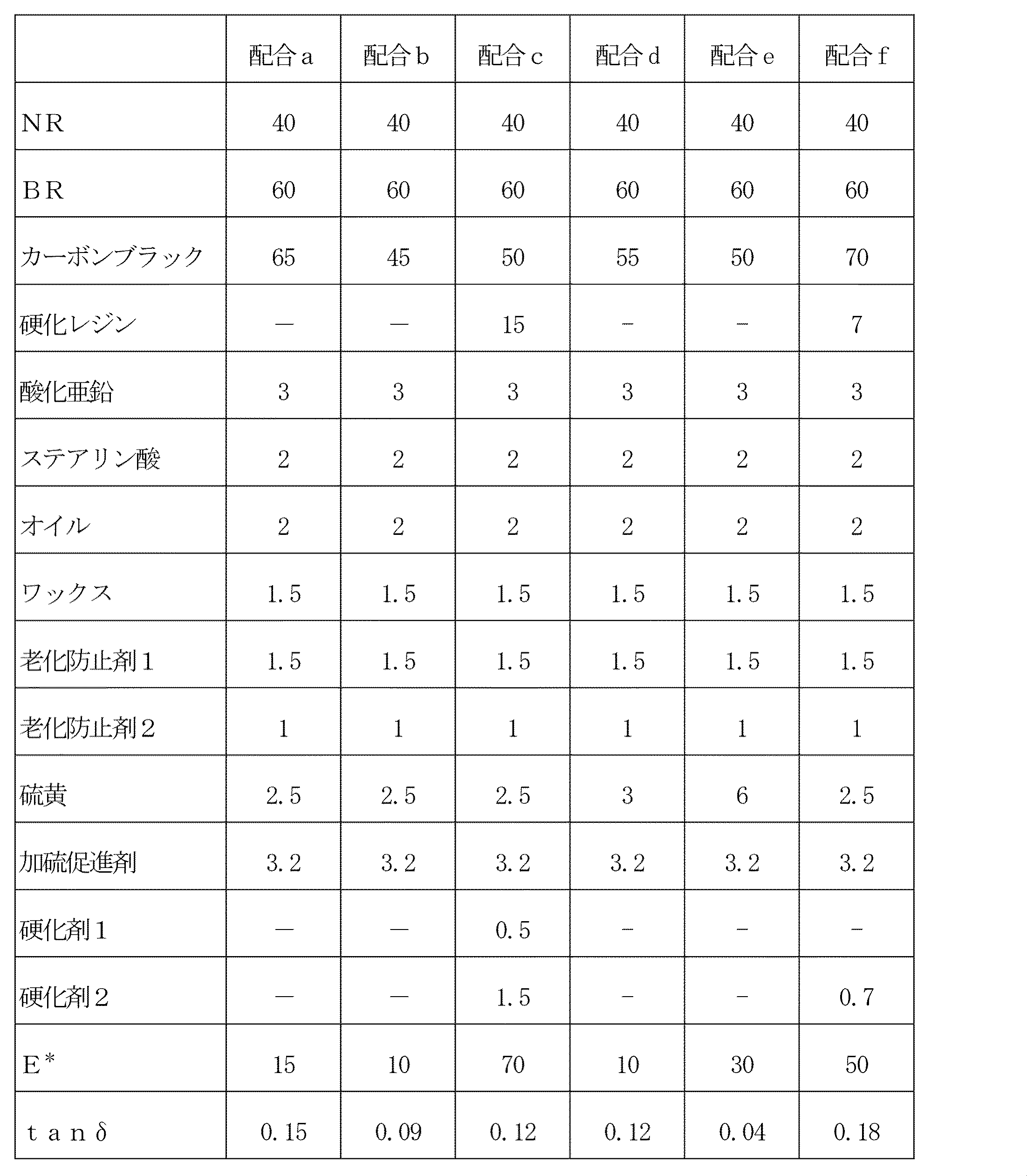
- Table 1 shows the ingredients and Table 2 and Table 3 show the ingredients.
- the unvulcanized rubber composition for clinch can be obtained.
- the rubber composition for electronic component 34 coating can be obtained.
- the obtained unvulcanized rubber composition is molded into the shape of a bead reinforcing layer or a clinch, respectively, and the unvulcanized rubber composition is laminated and bonded together with other tire members on a tire molding machine.
- the test tire (tyre size: 195 / 65R15) is obtained by setting the electronic component 34 coated in the above in any of FIG. 2A to FIG. 2E described later and vulcanizing under the condition of 150.degree. C. for 30 minutes. You can get it.
- the electronic component 34 an RFID in which a 30 mm antenna is provided on both sides of a 3 mm ⁇ 3 mm ⁇ 0.4 mm IC chip can be used.
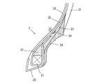
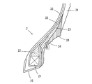
- FIGS. 2A to 2E Specific insertion positions of the electronic component 34 are shown in FIGS. 2A to 2E.
- the electronic component 34 is provided 31% below the bead core
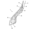
- the electronic component 34 is provided 40% below the bead core
- the electronic component 34 is located 12% below the bead core.
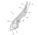
- the electronic component 34 is provided at a position 29% from below the bead core in FIG. 2D
- the electronic component 34 is provided at a position 21% from below the bead core in FIG. 2E.
- these values are values with respect to the distance from the position of the tire maximum width to the bottom of the bead core.
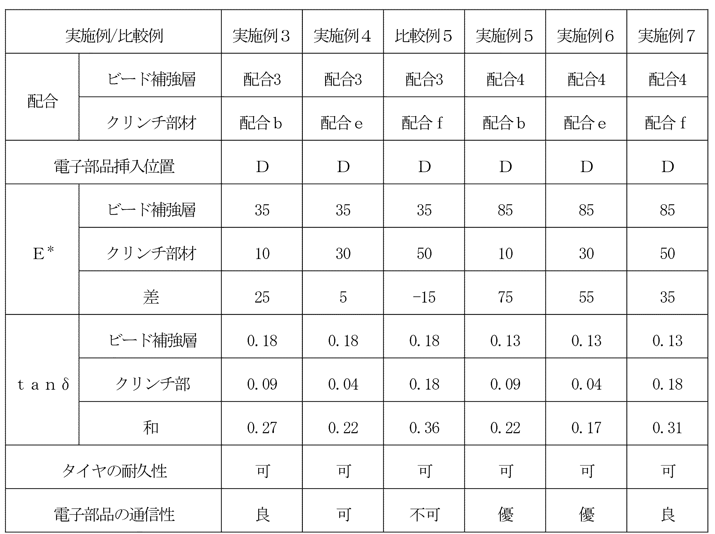
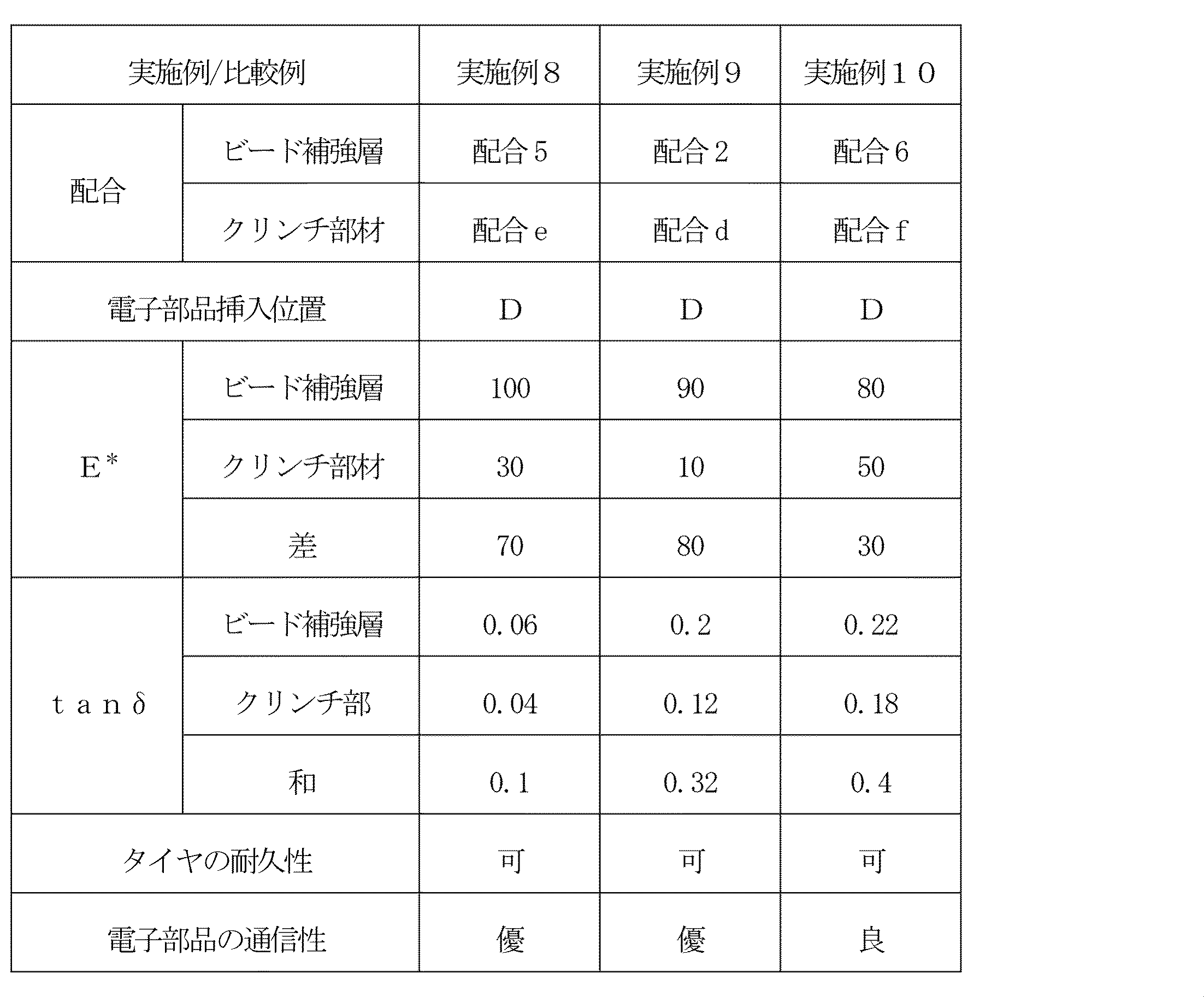
- Tables 4 to 7 show the relationship between the composition and physical properties of the bead reinforcing layer and the clinch, the position of the electronic component, the durability of the tire, and the communication performance of the electronic component.
- the evaluation of the durability of the tire is acceptable if it can travel 10,000 km on a general road, and it is not acceptable if it can not.
- the mounting rim is 15 ⁇ 6.5 J
- the tire internal pressure is 230 kPa
- the test vehicle is a front wheel drive vehicle
- the displacement is 2000 cc
- the tire mounting position is all wheels.
- the evaluation method of communication property installs the transceiver for the electronic component at three measurement points (a to c) of the circle shown in FIG. 3 and judges whether it is possible to communicate data with the electronic component Do.
- the tire is assembled in a rim and mounted in a vehicle, and measured (the number of readable positions after the durability evaluation / the number of readable positions before the durability evaluation) is calculated.
- the average value of the tire is excellent if it is 60% or more, good if it is 50% or more and less than 60%, it is acceptable if it is more than 0% and less than 50%, 0% or readable position before durability evaluation If the number of is 0, it is not possible.
Landscapes
- Engineering & Computer Science (AREA)
- Mechanical Engineering (AREA)
- Tires In General (AREA)
Abstract
電子部品が内部に埋め込まれたタイヤであっても、路面走行時の衝撃荷重などによって破壊されるようなことが抑制され、タイヤの耐久性の低下を招くことがないタイヤ製造技術を提供する。 ビード部のカーカスのタイヤ軸方向外側に設けられ、ビード部をカーカスの外側から補強するビード補強層と、ビード補強層のタイヤ軸方向外側に設けられているクリンチ部材と、電子部品とを備えており、クリンチ部材が、ビード補強層よりも低い剛性を有しており、電子部品が、ビード補強層とクリンチ部材との間に埋め込まれている空気入りタイヤ。
Description
本発明は、RFIDなどの電子部品が埋め込まれた空気入りタイヤに関する。
近年、空気入りタイヤ(以下、単に「タイヤ」ともいう)の内圧、温度、回転数などの諸データを監視し、車両走行中の安全性やメンテナンス性等を向上させるために、前記諸データを記録する、例えばRFID(Radio Frequency IDentification)用トランスポンダ(以下、単に「RFID」ともいう)等の電子部品をタイヤに取り付けることが提案されている。
なお、トランスポンダは、送受信回路、制御回路、メモリ等をチップ化した半導体と、アンテナとから構成される小型軽量の電子部品であり、質問電波を受信したとき、これを電気エネルギーとして使用しメモリ内の諸データを応答電波として発信しうるバッテリーレスのものが多用されている。
このような電子部品をタイヤに取り付ける方法として、加硫後のタイヤの表面に電子部品を接着等により貼り付ける方法(例えば、特許文献1)が提案されているが、この方法を採用した場合には電子部品が破壊される恐れは少ないものの、路面走行中に電子部品が脱落し易いなどの問題があった。
そこで、電子部品の脱落を防止するために、電子部品を未加硫タイヤの内部に埋め込んだ後、加硫成形に伴う加硫接着によりタイヤと一体化する方法(例えば、特許文献2)が提案されている。
しかしながら、電子部品を未加硫タイヤの内部に埋め込んだ後、タイヤと一体化する方法を採用した場合には、電子部品が脱落する恐れはないものの、路面走行時の衝撃荷重などにより破壊され易く、また、硬い電子部品が埋め込まれていることによりタイヤの耐久性が低下するなどの問題があり、さらなる改善が求められている。
そこで、本発明は、電子部品が内部に埋め込まれたタイヤであっても、路面走行時の衝撃荷重などによって破壊されるようなことが抑制され、タイヤの耐久性の低下を招くことがないタイヤ製造技術を提供することを課題とする。
本発明者は、上記課題の解決について鋭意検討を行い、以下に記載する発明により上記課題が解決できることを見出し、本発明を完成させるに至った。
請求項1に記載の発明は、
ビード部のカーカスのタイヤ軸方向外側に設けられ、前記ビード部を前記カーカスの外側から補強するビード補強層と、
前記ビード補強層のタイヤ軸方向外側に設けられているクリンチ部材と、
電子部品とを備えており、
前記クリンチ部材が、前記ビード補強層よりも低い剛性を有しており、
前記電子部品が、前記ビード補強層と前記クリンチ部材との間に埋め込まれていることを特徴とする空気入りタイヤである。
ビード部のカーカスのタイヤ軸方向外側に設けられ、前記ビード部を前記カーカスの外側から補強するビード補強層と、
前記ビード補強層のタイヤ軸方向外側に設けられているクリンチ部材と、
電子部品とを備えており、
前記クリンチ部材が、前記ビード補強層よりも低い剛性を有しており、
前記電子部品が、前記ビード補強層と前記クリンチ部材との間に埋め込まれていることを特徴とする空気入りタイヤである。
請求項2に記載の発明は、
前記ビード補強層および前記クリンチ部材は、それぞれゴム組成物からなり、
70℃における前記ビード補強層のE*(1)と前記クリンチ部材のE*(2)とが、下記式を満足することを特徴とする請求項1に記載の空気入りタイヤである。
E*(1)-E*(2)≧5MPa
前記ビード補強層および前記クリンチ部材は、それぞれゴム組成物からなり、
70℃における前記ビード補強層のE*(1)と前記クリンチ部材のE*(2)とが、下記式を満足することを特徴とする請求項1に記載の空気入りタイヤである。
E*(1)-E*(2)≧5MPa
請求項3に記載の発明は、
70℃における前記ビード補強層のE*(1)と前記クリンチ部材のE*(2)とが、下記式を満足することを特徴とする請求項2に記載の空気入りタイヤである。
E*(1)-E*(2)≧20MPa
70℃における前記ビード補強層のE*(1)と前記クリンチ部材のE*(2)とが、下記式を満足することを特徴とする請求項2に記載の空気入りタイヤである。
E*(1)-E*(2)≧20MPa
請求項4に記載の発明は、
70℃における前記ビード補強層のE*(1)と前記クリンチ部材のE*(2)とが、下記式を満足することを特徴とする請求項3に記載の空気入りタイヤである。
E*(1)-E*(2)≧40MPa
70℃における前記ビード補強層のE*(1)と前記クリンチ部材のE*(2)とが、下記式を満足することを特徴とする請求項3に記載の空気入りタイヤである。
E*(1)-E*(2)≧40MPa
請求項5に記載の発明は、
前記ビード補強層および前記クリンチ部材は、それぞれゴム組成物からなり、
70℃における前記ビード補強層のtanδ(1)と前記クリンチ部材のtanδ(2)とが下記式を満足することを特徴とする請求項1ないし請求項4のいずれか1項に記載の空気入りタイヤである。
tanδ(1)+tanδ(2)≦0.4
前記ビード補強層および前記クリンチ部材は、それぞれゴム組成物からなり、
70℃における前記ビード補強層のtanδ(1)と前記クリンチ部材のtanδ(2)とが下記式を満足することを特徴とする請求項1ないし請求項4のいずれか1項に記載の空気入りタイヤである。
tanδ(1)+tanδ(2)≦0.4
請求項6に記載の発明は、
70℃における前記ビード補強層のtanδ(1)と前記クリンチ部材のtanδ(2)とが下記式を満足することを特徴とする請求項5に記載の空気入りタイヤである。
tanδ(1)+tanδ(2)≦0.32
70℃における前記ビード補強層のtanδ(1)と前記クリンチ部材のtanδ(2)とが下記式を満足することを特徴とする請求項5に記載の空気入りタイヤである。
tanδ(1)+tanδ(2)≦0.32
請求項7に記載の発明は、
前記電子部品が、
断面図において、カーカスよりもタイヤ軸方向外側にあり、
赤道方向において、タイヤ最大幅の位置からビードコア下までの距離に対して、ビードコア下から20~80%の位置に埋め込まれていることを特徴とする請求項1ないし請求項6のいずれか1項に記載の空気入りタイヤである。
前記電子部品が、
断面図において、カーカスよりもタイヤ軸方向外側にあり、
赤道方向において、タイヤ最大幅の位置からビードコア下までの距離に対して、ビードコア下から20~80%の位置に埋め込まれていることを特徴とする請求項1ないし請求項6のいずれか1項に記載の空気入りタイヤである。
本発明によれば、電子部品が内部に埋め込まれたタイヤであっても、路面走行時の衝撃荷重などによって破壊されるようなことが抑制され、タイヤの耐久性の低下を招くことがないタイヤ製造技術を提供することができる。
以下、本発明を実施の形態に基づいて説明する。
[1]本発明に至る経緯
本発明者は、上記した課題の解決について検討した結果、通常走行時に変形の小さいビードエイペックスに隣接させて電子部品を配置することで、通常のゴムよりも硬い電子部品の破壊を抑制できると考えた。しかし、カーカスプライがビードエイペックスを巻き上げる構造の場合、ビードエイペックスに電子部品を隣接させると巻き上げの支障になることが懸念された。そこで、ビードエイペックスを小さくし、その代わりにビード補強層をカーカスプライの端部よりも外側に配置して、そのビード補強層に電子部品を近接させ、ビード補強層とクリンチとの間に電子部品を設けることにした。
本発明者は、上記した課題の解決について検討した結果、通常走行時に変形の小さいビードエイペックスに隣接させて電子部品を配置することで、通常のゴムよりも硬い電子部品の破壊を抑制できると考えた。しかし、カーカスプライがビードエイペックスを巻き上げる構造の場合、ビードエイペックスに電子部品を隣接させると巻き上げの支障になることが懸念された。そこで、ビードエイペックスを小さくし、その代わりにビード補強層をカーカスプライの端部よりも外側に配置して、そのビード補強層に電子部品を近接させ、ビード補強層とクリンチとの間に電子部品を設けることにした。
さらに検討を進めた結果、ビード補強層とクリンチ部の間に電子部品を配置するに際して、クリンチ部のゴム材料が硬いと、外部からの衝撃が電子部品に伝わり易くなり、電子部品の損傷を招く恐れがあるため、クリンチ部の剛性をビード補強層の剛性よりも低くする必要があることが考えられた。そして、これにより、外部からの衝撃が電子部品に伝わり難くなり、埋め込まれた電子部品の耐久性が向上すると考え、本発明を完成するに至った。
即ち、本発明に係るタイヤは、クリンチ部材がビード補強層よりも低い剛性を有しており、電子部品がビード補強層とクリンチ部材との間に埋め込まれているタイヤであり、その結果、路面走行時の衝撃荷重などによって電子部品が破壊されるようなことが抑制され、また、タイヤの耐久性の低下を招くことがないタイヤを提供することができる。
[2]本発明の実施の形態
1.タイヤの構成
(1)全体構成
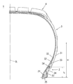
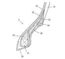
本実施の形態に係るタイヤは、ビード補強層と、タイヤ内に埋設された電子部品とを備えている。本実施の形態のタイヤを図1を参照し説明する。図1は本発明の一実施の形態に係るタイヤの構成を示す断面図であり、具体的には、サイズ235/75R15のタイヤの断面図である。
1.タイヤの構成
(1)全体構成
本実施の形態に係るタイヤは、ビード補強層と、タイヤ内に埋設された電子部品とを備えている。本実施の形態のタイヤを図1を参照し説明する。図1は本発明の一実施の形態に係るタイヤの構成を示す断面図であり、具体的には、サイズ235/75R15のタイヤの断面図である。
図1において、1はタイヤであり、2はビード部であり、3はサイドウォール部であり、4はトレッドである。21はビードコアであり、22はビードエイペックスであり、23はビード補強層であり、24はクリンチ部材(以下、「クリンチ」ともいう)である。なお、このクリンチは、サイドウォールよりもタイヤ径方向内側に位置し、かつ、ビード補強層よりもタイヤ軸方向外側に位置する外部部材である。また、25はチェーファである。さらに、31はサイドウォールであり、32はカーカスプライであり、33はインナーライナである。また、34は電子部品である。なお、図1において、Hはタイヤ最大幅の位置からビードコア下までの距離であり、Lは電子部品34のビードコア下からの距離である。
(2)ビード部の構成
ビード補強層23は、ビード部2のカーカスプライ32のタイヤ軸方向外側(図1においては右側)に配置されて、ビードエイペックスの変形を抑制する。タイヤ軸方向とはタイヤの回転軸線と平行な方向であり、タイヤ軸方向外側とは、タイヤ赤道CLを通る平面を中心とした場合に軸方向において外側であることを意味する。
ビード補強層23は、ビード部2のカーカスプライ32のタイヤ軸方向外側(図1においては右側)に配置されて、ビードエイペックスの変形を抑制する。タイヤ軸方向とはタイヤの回転軸線と平行な方向であり、タイヤ軸方向外側とは、タイヤ赤道CLを通る平面を中心とした場合に軸方向において外側であることを意味する。
また、ビード補強層23のタイヤ軸方向外側に隣接してクリンチ24が配置されており、電子部品34はビード補強層23とクリンチ24の間に埋設されている。なお、電子部品34はビード補強層23とクリンチ24との間であれば直接隣接している必要はなく、例えば、ビード補強層23およびクリンチ24とは別のゴム材料によって被覆されていてもよい。
(3)ビード補強層およびクリンチのゴム物性
(a)ビード補強層とクリンチの剛性
本実施の形態のタイヤにおいては、クリンチ24は、ビード補強層23より剛性が低い。ゴムの剛性は、通常、E*(複素弾性率)などで表され、剛性が低いとは、クリンチ24がビード補強層23より、E*の値が低いことを意味する。なお、本願においてE*は絶対値を意味する。
(a)ビード補強層とクリンチの剛性
本実施の形態のタイヤにおいては、クリンチ24は、ビード補強層23より剛性が低い。ゴムの剛性は、通常、E*(複素弾性率)などで表され、剛性が低いとは、クリンチ24がビード補強層23より、E*の値が低いことを意味する。なお、本願においてE*は絶対値を意味する。
また、ビード補強層23およびクリンチ24の70℃におけるE*をそれぞれE*(1)MPa、E*(2)MPaとしたとき、(E*(1)-E*(2))は、下記式を満たしていることが好ましく、20MPa以上であればより好ましく、40MPa以上であればさらに好ましい。
E*(1)-E*(2)≧5MPa
E*(1)-E*(2)≧5MPa
本発明の効果を発揮させるために、上記式の上限を設定しなければならないということはないが、タイヤの製造の容易さの面から、80MPa以下が好ましく、75MPa以下であればより好ましい。
なお、上記におけるE*は、「JIS K 6394」の規定に準拠して、粘弾性スペクトロメーター(例えば、岩本製作所製の「VESF-3」)を用いて、下記に示される条件下で計測される値であり、ビード補強層用ゴム組成物の70℃におけるE*(1)は、例えば、10~130MPaであり、クリンチ用ゴム組成物の70℃におけるE*(2)は、例えば、7~80MPaである。
初期歪み :10%
振幅 :±2.0%
周波数 :10Hz
変形モード:引張
測定温度 :70℃
初期歪み :10%
振幅 :±2.0%
周波数 :10Hz
変形モード:引張
測定温度 :70℃
そして、上記に例示した範囲のE*(1)のビード補強層用ゴム組成物を用いる場合、上記式を満足するE*(2)のクリンチ用ゴム組成物が用いられる。同じく上記に例示した範囲のE*(2)のクリンチ用ゴム組成物を用いる場合、上記式を満足するE*(1)のビード補強層用ゴム組成物が用いられる。
このように、クリンチ24のE*(2)をビード補強層23のE*(1)よりも小さくすることにより、特に、その差を上記式のように適切に制御することにより、車の操縦安定性の維持およびタイヤの耐久性の低下の抑制に加えて、電子部品への衝撃を緩和して電子部品の損傷を抑制することができる。
(b)ビード補強層とクリンチの発熱性
本実施の形態のタイヤにおいては電子部品の周辺部材が変形しにくく発熱しにくいが、それでも発熱する。この発熱が抑制されないと、電子部品が高温化されて損傷する恐れがある。
本実施の形態のタイヤにおいては電子部品の周辺部材が変形しにくく発熱しにくいが、それでも発熱する。この発熱が抑制されないと、電子部品が高温化されて損傷する恐れがある。
このため、本実施の形態においては、ビード補強層23およびクリンチ24の70℃におけるtanδをそれぞれtanδ(1)、tanδ(2)としたとき、(tanδ(1)+tanδ(2))が、下記式を満足することが好ましく、0.32以下であるとより好ましい。
tanδ(1)+tanδ(2)≦0.4
tanδ(1)+tanδ(2)≦0.4
本発明の効果を発揮させるために、上記式の下限を設定しなければならないということはないが、タイヤの製造の容易さの面から、0.1以上が好ましく、0.17以上であればより好ましい。
なお、上記におけるtanδは、上記したE*の測定と同様にして計測される値であり、ビード補強層用ゴム組成物の70℃におけるtanδ(1)は、例えば、0.02~0.25であり、クリンチ用ゴム組成物の70℃におけるtanδ(2)は、例えば、0.02~0.29である。
そして、上記に例示した範囲のtanδ(1)のビード補強層用ゴム組成物を用いる場合、上記式を満足するtanδ(2)のクリンチ用ゴム組成物が用いられる。同じく上記に例示した範囲のtanδ(2)のクリンチ用ゴム組成物を用いる場合、上記式を満足するtanδ(1)のビード補強層用ゴム組成物が用いられる。
このように、ビード補強層23およびクリンチ24のtanδを適切に制御することにより、ビード補強層23とクリンチ24のいずれもが発熱性が低い場合には電子部品周辺の高温化を抑制することができる。また、いずれか一方が低い場合にも、高い方から低い方へ熱を逃がすことができるため、やはり、電子部品周辺の高温化を抑制することができる。
(4)電子部品
本実施の形態に係るタイヤには電子部品が埋め込まれている。具体的な電子部品としては、例えば、RFID、圧力センサ、温度センサ、加速度センサ、磁気センサ、溝深さセンサなどが挙げられる。中でも、RFIDは大容量の情報を記憶して非接触で読み取ることができるため、圧力、温度などのデータに加えて、タイヤの製造情報や管理情報、顧客情報なども記憶させることができるため、特に好ましい。
本実施の形態に係るタイヤには電子部品が埋め込まれている。具体的な電子部品としては、例えば、RFID、圧力センサ、温度センサ、加速度センサ、磁気センサ、溝深さセンサなどが挙げられる。中でも、RFIDは大容量の情報を記憶して非接触で読み取ることができるため、圧力、温度などのデータに加えて、タイヤの製造情報や管理情報、顧客情報なども記憶させることができるため、特に好ましい。
本実施の形態において、電子部品34はビード補強層23とクリンチ24の間に埋め込まれている。これにより、タイヤ内層のカーカス側に電子部品を配置した場合と比較して、局所的な応力集中が発生してカーカスの破断起点となるようなことを抑制することができる。具体的な埋め込み位置としては、確実な情報の通信が可能で、タイヤの変形による電子部品の損傷を受け難い箇所であれば、特に限定されないが、タイヤの変形による電子部品の損傷が比較的少なく、リム組みした際、外部から問題なく通信可能な位置として、タイヤの断面図において、カーカスの端部よりもタイヤ軸方向外側にあり、赤道方向において、タイヤ最大幅の位置からビードコア下までの距離(図1におけるH)に対して、ビードコア下からの高さ(図1におけるL)が20~80%となる位置に配置されることが好ましい。
なお、本実施の形態において埋め込まれる電子部品の長手方向の大きさ(ICチップとアンテナとを含めた全長)としては、18cm以下であることが好ましく、9cm以下であるとより好ましく、4cm以下であるとさらに好ましく、2cm以下であることが最も好ましい。このように小さなサイズとすることにより、周囲のゴムに応力が集中してしまう可能性があるが、本実施の形態においては、上記したように、局所的な応力集中に対する配慮がなされているため、タイヤの耐久性を安定して維持することができる。このとき、電子部品のアンテナ部分をカーカスのコードと直交する方向に伸びるように配置することにより、アンテナ部分の曲げを最小に維持することができる。
(5)ゴム組成物
(a)ビード補強層のゴム組成物
本実施の形態において、ビード補強層の製造に用いられるゴム組成物は、主成分であるゴム成分および硬化レジン、補強材、老化防止剤、添加剤などの各種配合材料を混練することにより得ることができる。
(a)ビード補強層のゴム組成物
本実施の形態において、ビード補強層の製造に用いられるゴム組成物は、主成分であるゴム成分および硬化レジン、補強材、老化防止剤、添加剤などの各種配合材料を混練することにより得ることができる。
(イ)ゴム成分
ゴム成分としては、例えば、天然ゴム(NR)、イソプレンゴム(IR)、ブタジエンゴム(BR)、スチレンブタジエンゴム(SBR)、アクリロニトリルブタジエンゴム(NBR)、クロロプレンゴム(CR)、ブチルゴム(IIR)などのジエン系ゴムが挙げられる。なかでも、操縦安定性、低燃費性及び押出加工性を良好に改善できるという点から、イソプレン系ゴム(NRやIR)が好ましい。
ゴム成分としては、例えば、天然ゴム(NR)、イソプレンゴム(IR)、ブタジエンゴム(BR)、スチレンブタジエンゴム(SBR)、アクリロニトリルブタジエンゴム(NBR)、クロロプレンゴム(CR)、ブチルゴム(IIR)などのジエン系ゴムが挙げられる。なかでも、操縦安定性、低燃費性及び押出加工性を良好に改善できるという点から、イソプレン系ゴム(NRやIR)が好ましい。
イソプレン系ゴム(NRやIR)の含有量としては、ゴム成分100質量部中に50質量部以上であることが好ましく、60質量部以上であるとより好ましい。イソプレン系ゴム(NRやIR)の含有量を上記のようにすることにより、十分な破断強度と十分な硬度を確保することができる。
(ロ)硬化レジン
ビード補強層のゴム組成物には、剛性を高めるための硬化レジンが配合されていることが好ましい。硬化レジンとしては、特に限定されないが、フェノール系樹脂が挙げられる。
ビード補強層のゴム組成物には、剛性を高めるための硬化レジンが配合されていることが好ましい。硬化レジンとしては、特に限定されないが、フェノール系樹脂が挙げられる。
具体的なフェノール系樹脂としては、フェノール樹脂、変性フェノール樹脂などが挙げられる。ここで、フェノール樹脂は、フェノールと、ホルムアルデヒド、アセトアルデヒド、フルフラールなどのアルデヒド類とを酸又はアルカリ触媒で反応させることにより得られるものであり、変性フェノール樹脂は、カシューオイル、トールオイル、アマニ油、各種動植物油、不飽和脂肪酸、ロジン、アルキルベンゼン樹脂、アニリン、メラミンなどの化合物を用いて変性したフェノール樹脂である。
フェノール系樹脂としては、硬化反応により良好な硬度が得られるという点から、変性フェノール樹脂が好ましく、カシューオイル変性フェノール樹脂、ロジン変性フェノール樹脂がより好ましい。
ゴム組成物における硬化レジンの含有量は、ゴム成分100質量部に対して5質量部以上であることが好ましく、10質量部以上であるとより好ましい。また、25質量部以下であることが好ましく、20質量部以下であるとより好ましい。硬化レジンの含有量を上記範囲内とすることにより、十分な剛性、操縦安定性を確保することができる。
硬化レジンとしてフェノール系樹脂を配合する場合、フェノール系樹脂との間で硬化作用を有する硬化剤をさらに含有することが好ましい。具体的な硬化剤としては、上記硬化作用を有するものであれば特に限定されず、例えば、ヘキサメチレンテトラミン(HMT)、ヘキサメトキシメチロールメラミン(HMMM)、ヘキサメトキシメチロールパンタメチルエーテル(HMMPME)、メラミン、メチロールメラミンなどが挙げられる。なかでも、フェノール系樹脂の硬度を上昇させる作用に優れるという点から、HMT、HMMM、HMMPMEが好ましい。
硬化剤の含有量は、フェノール系樹脂100質量部に対して、1質量部以上であることが好ましく、5質量部以上であるとより好ましい。1質量部未満であると、充分に硬化できない場合がある。また、20質量部以下であることが好ましく、15質量部以下であるとより好ましい。20質量部を超えると、硬化が不均一になるおそれや、押出し時にスコーチが発生する恐れがある。
(ハ)カーボンブラック
本実施の形態のゴム組成物には、補強材としてカーボンブラックを配合することが好ましい。カーボンブラックとしては、例えば、GPF、HAF、ISAF、SAF、FF、FEFなどが挙げられる。これらのカーボンブラックは1種を単独で用いてもよく、2種以上を組み合わせて用いてもよい。これらの中でも、硬度を確保するという観点から、ハードカーボン系のISAF、SAF、HAFが好ましく、内でも、HAFが特に好ましい。
本実施の形態のゴム組成物には、補強材としてカーボンブラックを配合することが好ましい。カーボンブラックとしては、例えば、GPF、HAF、ISAF、SAF、FF、FEFなどが挙げられる。これらのカーボンブラックは1種を単独で用いてもよく、2種以上を組み合わせて用いてもよい。これらの中でも、硬度を確保するという観点から、ハードカーボン系のISAF、SAF、HAFが好ましく、内でも、HAFが特に好ましい。
上記ゴム組成物中におけるカーボンブラックの含有量としては、ゴム成分100質量部に対して、30質量部以上であることが好ましく、45質量部以上であるとより好ましい。また、70質量部以下であることが好ましく、65質量部以下であるとより好ましい。ゴム組成物中のカーボンブラックの量を上記の範囲内とすることにより、十分な破壊特性が得られる。
(ニ)加硫剤および加硫促進剤
硫黄は加硫剤として使用され、その含有量は、ゴム成分100質量部に対して、1質量部以上であることが好ましく、2質量部以上であるとより好ましい。また、8質量部以下であることが好ましく、6質量部以下であるとより好ましい。硫黄の含有量を上記範囲内とすることにより、十分な操縦安定性を確保することができ、硫黄のブルームや粘着性を抑制し、また、耐久性を確保することができる。なお、硫黄の含有量は、純硫黄分量であり、不溶性硫黄を用いる場合はオイル分を除いた含有量である。
硫黄は加硫剤として使用され、その含有量は、ゴム成分100質量部に対して、1質量部以上であることが好ましく、2質量部以上であるとより好ましい。また、8質量部以下であることが好ましく、6質量部以下であるとより好ましい。硫黄の含有量を上記範囲内とすることにより、十分な操縦安定性を確保することができ、硫黄のブルームや粘着性を抑制し、また、耐久性を確保することができる。なお、硫黄の含有量は、純硫黄分量であり、不溶性硫黄を用いる場合はオイル分を除いた含有量である。
硫黄は、通常、加硫促進剤と共に使用される。加硫促進剤の含有量は、ゴム成分100質量部に対して、1.5質量部以上であることが好ましく、2.0質量部以上であるとより好ましい。また、5.0質量部以下であることが好ましく、4.0質量部以下であるとより好ましい。加硫促進剤の含有量を上記範囲内とすることにより、本発明の効果を良好に得られる傾向がある。具体的な加硫促進剤としては、例えば、スルフェンアミド系、チアゾール系、チウラム系、チオウレア系、グアニジン系、ジチオカルバミン酸系、アルデヒド-アミン系若しくはアルデヒド-アンモニア系、イミダゾリン系、又はキサンテート系加硫促進剤等が挙げられる。これら加硫促進剤は、単独で用いてもよく、2種以上を併用してもよい。なかでも、スコーチ時間と加硫時間をバランスさせられるという理由から、スルフェンアミド系加硫促進剤が好ましい。
(ホ)ステアリン酸
ステアリン酸としては、従来公知のものを使用でき、例えば、日油(株)、NOF社、花王(株)、和光純薬工業(株)、千葉脂肪酸(株)等の製品を使用できる。ステアリン酸を使用する場合、ステアリン酸の含有量は、ゴム成分100質量部に対して、0.5質量部以上であることが好ましく、1質量部以上であるとより好ましい。また、10質量部以下であることが好ましく、5質量部以下であるとより好ましい。ステアリン酸の含有量を上記範囲内とすることにより、本発明の効果が良好に得られる傾向がある。
ステアリン酸としては、従来公知のものを使用でき、例えば、日油(株)、NOF社、花王(株)、和光純薬工業(株)、千葉脂肪酸(株)等の製品を使用できる。ステアリン酸を使用する場合、ステアリン酸の含有量は、ゴム成分100質量部に対して、0.5質量部以上であることが好ましく、1質量部以上であるとより好ましい。また、10質量部以下であることが好ましく、5質量部以下であるとより好ましい。ステアリン酸の含有量を上記範囲内とすることにより、本発明の効果が良好に得られる傾向がある。
(ヘ)酸化亜鉛
酸化亜鉛としては、従来公知のものを使用でき、例えば、三井金属鉱業(株)、東邦亜鉛(株)、ハクスイテック(株)、正同化学工業(株)、堺化学工業(株)等の製品を使用できる。酸化亜鉛を使用する場合、酸化亜鉛の含有量は、ゴム成分100質量部に対して、0.5質量部以上であることが好ましく、1質量部以上であるとより好ましい。また、10質量部以下であることが好ましく、5質量部以下であるとより好ましい。酸化亜鉛の含有量を上記範囲内とすることにより、本発明の効果がより良好に得られる傾向がある。
酸化亜鉛としては、従来公知のものを使用でき、例えば、三井金属鉱業(株)、東邦亜鉛(株)、ハクスイテック(株)、正同化学工業(株)、堺化学工業(株)等の製品を使用できる。酸化亜鉛を使用する場合、酸化亜鉛の含有量は、ゴム成分100質量部に対して、0.5質量部以上であることが好ましく、1質量部以上であるとより好ましい。また、10質量部以下であることが好ましく、5質量部以下であるとより好ましい。酸化亜鉛の含有量を上記範囲内とすることにより、本発明の効果がより良好に得られる傾向がある。
(ト)老化防止剤
老化防止剤としては、優れた耐オゾン効果を有するアミン系老化防止剤が好適である。アミン系老化防止剤としては、特に限定されず、例えば、ジフェニルアミン系、p-フェニレンジアミン系、ナフチルアミン系、ケトンアミン縮合物系などのアミン誘導体が挙げられ、これらは1種を単独で用いてもよく、2種以上を組み合わせて用いてもよい。ジフェニルアミン系誘導体としては、例えば、p-(p-トルエンスルホニルアミド)-ジフェニルアミン、オクチル化ジフェニルアミン、4,4’-ビス(α,α’-ジメチルベンジル)ジフェニルアミンなどが挙げられる。p-フェニレンジアミン系誘導体としては、例えば、N-(1,3-ジメチルブチル)-N’-フェニル-p-フェニレンジアミン(6PPD)、N-フェニル-N’-イソプロピル-p-フェニレンジアミン(IPPD)、N,N’-ジ-2-ナフチル-p-フェニレンジアミンなどが挙げられる。ナフチルアミン系誘導体としては、フェニル-α-ナフチルアミンなどが挙げられる。中でも、フェニレンジアミン系、ケトンアミン縮合物系が好ましい。老化防止剤の含有量は、ゴム成分100質量部に対して、0.3質量部以上であることが好ましく、0.5質量部以上であるとより好ましい。また、8質量部以下であることが好ましく、2.5質量部以下であるとより好ましい。
老化防止剤としては、優れた耐オゾン効果を有するアミン系老化防止剤が好適である。アミン系老化防止剤としては、特に限定されず、例えば、ジフェニルアミン系、p-フェニレンジアミン系、ナフチルアミン系、ケトンアミン縮合物系などのアミン誘導体が挙げられ、これらは1種を単独で用いてもよく、2種以上を組み合わせて用いてもよい。ジフェニルアミン系誘導体としては、例えば、p-(p-トルエンスルホニルアミド)-ジフェニルアミン、オクチル化ジフェニルアミン、4,4’-ビス(α,α’-ジメチルベンジル)ジフェニルアミンなどが挙げられる。p-フェニレンジアミン系誘導体としては、例えば、N-(1,3-ジメチルブチル)-N’-フェニル-p-フェニレンジアミン(6PPD)、N-フェニル-N’-イソプロピル-p-フェニレンジアミン(IPPD)、N,N’-ジ-2-ナフチル-p-フェニレンジアミンなどが挙げられる。ナフチルアミン系誘導体としては、フェニル-α-ナフチルアミンなどが挙げられる。中でも、フェニレンジアミン系、ケトンアミン縮合物系が好ましい。老化防止剤の含有量は、ゴム成分100質量部に対して、0.3質量部以上であることが好ましく、0.5質量部以上であるとより好ましい。また、8質量部以下であることが好ましく、2.5質量部以下であるとより好ましい。
(チ)ワックス
ワックスとしては、特に限定されず、パラフィンワックス、マイクロクリスタリンワックス等の石油系ワックス;植物系ワックス、動物系ワックス等の天然系ワックス;エチレン、プロピレン等の重合物等の合成ワックスなどが挙げられる。これらは、単独で用いてもよく、2種以上を併用してもよい。具体的なワックスとしては、例えば、大内新興化学工業(株)、日本精蝋(株)、精工化学(株)等の製品を使用できる。ワックスを使用する場合、ワックスの含有量は、ゴム成分100質量部に対して、0.5質量部以上であることが好ましく、1質量部以上であるとより好ましい。また、10質量部以下であることが好ましく、7質量部以下であるとより好ましい。
ワックスとしては、特に限定されず、パラフィンワックス、マイクロクリスタリンワックス等の石油系ワックス;植物系ワックス、動物系ワックス等の天然系ワックス;エチレン、プロピレン等の重合物等の合成ワックスなどが挙げられる。これらは、単独で用いてもよく、2種以上を併用してもよい。具体的なワックスとしては、例えば、大内新興化学工業(株)、日本精蝋(株)、精工化学(株)等の製品を使用できる。ワックスを使用する場合、ワックスの含有量は、ゴム成分100質量部に対して、0.5質量部以上であることが好ましく、1質量部以上であるとより好ましい。また、10質量部以下であることが好ましく、7質量部以下であるとより好ましい。
(リ)オイル
オイルとしては、例えば、プロセスオイル、植物油脂、又はその混合物が挙げられる。プロセスオイルとしては、例えば、パラフィン系プロセスオイル、アロマ系プロセスオイル、ナフテン系プロセスオイルなどを用いることができる。植物油脂としては、ひまし油、綿実油、あまに油、なたね油、大豆油、パーム油、やし油、落花生油、ロジン、パインオイル、パインタール、トール油、コーン油、こめ油、べに花油、ごま油、オリーブ油、ひまわり油、パーム核油、椿油、ホホバ油、マカデミアナッツ油、桐油等が挙げられる。これらは、単独で用いてもよく、2種以上を併用してもよい。具体的なオイルとしては、例えば、出光興産(株)、三共油化工業(株)、(株)ジャパンエナジー、オリソイ社、H&R社、豊国製油(株)、昭和シェル石油(株)、富士興産(株)等の製品を使用できる。オイルの含有量は、ゴム成分100質量部に対して0.5質量部以上であることが好ましく、1質量部以上であるとより好ましい。また、10質量部以下であることが好ましく、5質量部以下であるとより好ましい。
オイルとしては、例えば、プロセスオイル、植物油脂、又はその混合物が挙げられる。プロセスオイルとしては、例えば、パラフィン系プロセスオイル、アロマ系プロセスオイル、ナフテン系プロセスオイルなどを用いることができる。植物油脂としては、ひまし油、綿実油、あまに油、なたね油、大豆油、パーム油、やし油、落花生油、ロジン、パインオイル、パインタール、トール油、コーン油、こめ油、べに花油、ごま油、オリーブ油、ひまわり油、パーム核油、椿油、ホホバ油、マカデミアナッツ油、桐油等が挙げられる。これらは、単独で用いてもよく、2種以上を併用してもよい。具体的なオイルとしては、例えば、出光興産(株)、三共油化工業(株)、(株)ジャパンエナジー、オリソイ社、H&R社、豊国製油(株)、昭和シェル石油(株)、富士興産(株)等の製品を使用できる。オイルの含有量は、ゴム成分100質量部に対して0.5質量部以上であることが好ましく、1質量部以上であるとより好ましい。また、10質量部以下であることが好ましく、5質量部以下であるとより好ましい。
(ヌ)その他
本実施の形態のゴム組成物には、前記成分以外にも、従来ゴム工業で使用される配合材料、例えば、シリカやタルク、炭酸カルシウムなどの無機充填材、セルロース繊維などの有機充填材、液状ゴムや粘着レジンなどの軟化剤、硫黄以外の加硫剤や有機架橋剤などを必要に応じて配合してもよい。各配合材料の配合量については適宜選択することができる。
本実施の形態のゴム組成物には、前記成分以外にも、従来ゴム工業で使用される配合材料、例えば、シリカやタルク、炭酸カルシウムなどの無機充填材、セルロース繊維などの有機充填材、液状ゴムや粘着レジンなどの軟化剤、硫黄以外の加硫剤や有機架橋剤などを必要に応じて配合してもよい。各配合材料の配合量については適宜選択することができる。
前記した通り、ビード補強層は、クリンチに対して、E*およびtanδが所定の関係式を満たすように調整されることが好ましい。ビード補強層のE*の調整方法としては、硬化レジンの増減による調整が挙げられる。後述する実施例にて示される通り、硬化レジンを増量することでE*を増加させることができる。また、カーボンブラックや硫黄量の増減でもE*を調整することができる。後述する実施例にて示される通り、カーボンブラックや硫黄を増量することでE*を増加させることができる。ただし、カーボンブラックを増量するとtanδが上昇し、硫黄を増量するとtanδが下降する。従って、まず、硬化レジンの使用の有無および配合量を定めた後、次に硫黄量を調整し、最後にカーボンブラック量を調整するという手段を採用することが好ましく、これにより、過度な試行錯誤を必要とせずに、狙いのE*およびtanδを達成することができる。
(b)クリンチのゴム組成物
クリンチ24のゴム組成物は、基本的にはビード補強層23に用いられるゴム組成物と同様であるが、クリンチ24のゴム組成物は、ビード補強層のゴム組成物と比較して剛性が低くなるよう調整される。本実施の形態においては、ゴム成分以外を同一の材料として、配合量を調整することが可能であるため、以下ではこの形態におけるゴム成分について説明する。
クリンチ24のゴム組成物は、基本的にはビード補強層23に用いられるゴム組成物と同様であるが、クリンチ24のゴム組成物は、ビード補強層のゴム組成物と比較して剛性が低くなるよう調整される。本実施の形態においては、ゴム成分以外を同一の材料として、配合量を調整することが可能であるため、以下ではこの形態におけるゴム成分について説明する。
ゴム成分としては、基本的にはビード補強層と同様のゴム成分を使用できるが、例えば、低燃費性、耐久性が良好に得られるという理由から、イソプレン系ゴム(NRやIR)とBRの併用がより好ましい。
イソプレン系ゴム(NRやIR)においては、ゴム成分100質量部中の含有量は、10質量部以上であることが好ましく、30質量部以上であるとより好ましい。また、80質量部以下であることが好ましく、50質量部以下であるとより好ましい。ゴム成分中のイソプレン系ゴム(NRやIR)の含有量を上記範囲内とすることにより、十分な破断伸びと十分な耐屈曲亀裂成長性を確保することができる。
BRにおいては、ゴム成分100質量部中の含有量は20質量部以上であることが好ましく、50質量部以上であるとより好ましい。また、90質量部以下であることが好ましく、70質量部以下であるとより好ましい。ゴム成分中のBRの含有量を上記範囲内とすることにより、十分な耐屈曲亀裂成長性と十分な破断強度を確保することができる。
なお、BRとしては、特に限定されず、例えば、高シス含有量のBR、シンジオタクチックポリブタジエン結晶を含有するBR(SPB含有BR)、変性BRなどを使用できる。中でも、内在した配向性の結晶成分により押出加工性を大きく改善できるという点から、SPB含有BRが好ましい。
イソプレン系ゴム(NRやIR)とBRの併用においては、イソプレン系ゴム(NRやIR)とBRの合計含有量は、ゴム成分100質量部中80質量部以上が好ましく、90質量部以上がより好ましい。イソプレン系ゴム(NRやIR)とBRの合計含有量を上記範囲内とすることにより、十分な低燃費性と十分な耐久性を確保することができる。
前記した通り、クリンチは、ビード補強層に対して剛性が低く構成され、好ましくはE*およびtanδが所定の関係式を満たすように調整される。クリンチのE*の調整方法としては、ビード補強層と同様の調整方法が挙げられるが、硬化レジンはできるだけ使用せずにカーボンブラックや硫黄の量で調整することが好ましい。即ち、まず硫黄量を調整し、次にカーボンブラック量を調整し、最後に硬化レジン量を調整することが好ましい。これにより、過度な試行錯誤を必要とせずに、狙いのE*およびtanδを達成することができる。
(c)ゴム組成物の製造方法
ビード補強層とクリンチのゴム組成物は、公知の方法、例えば、前記各成分をオープンロール、バンバリーミキサなどのゴム混練装置を用いて、それぞれを混練することにより製造することができる。
ビード補強層とクリンチのゴム組成物は、公知の方法、例えば、前記各成分をオープンロール、バンバリーミキサなどのゴム混練装置を用いて、それぞれを混練することにより製造することができる。
2.タイヤの製造
本実施の形態のタイヤは、成形途中に電子部品を埋め込むこと以外は、通常の方法によって製造することができる。即ち、ビード補強層23およびクリンチ24は、前記ゴム組成物を未加硫の段階でビードエイペックスの形状に合わせて押出加工により成形しタイヤ成形機上にて通常の方法にて他のタイヤ部材と共に貼り合わせ、未加硫タイヤを成形する。そして、この成形の途中、ビード補強層とクリンチとの間の所定の位置に電子部品を埋め込む。
本実施の形態のタイヤは、成形途中に電子部品を埋め込むこと以外は、通常の方法によって製造することができる。即ち、ビード補強層23およびクリンチ24は、前記ゴム組成物を未加硫の段階でビードエイペックスの形状に合わせて押出加工により成形しタイヤ成形機上にて通常の方法にて他のタイヤ部材と共に貼り合わせ、未加硫タイヤを成形する。そして、この成形の途中、ビード補強層とクリンチとの間の所定の位置に電子部品を埋め込む。
その後、電子部品が埋め込まれて成形された未加硫タイヤを加硫機中で加熱加圧することにより、タイヤを製造する。
1.配合材料および配合処方
配合材料を表1に、配合処方を表2、表3に示す。
配合材料を表1に、配合処方を表2、表3に示す。


2.空気入りタイヤの作製
表1および表2に基づき、神戸製鋼(株)製バンバリーミキサを用いて、硫黄及び加硫促進剤以外の配合材料を混練りし、得られる混練り物に硫黄及び加硫促進剤を添加し、オープンロールを用いて練り込むことで、ビード補強層用の未加硫ゴム組成物を得ることができる。
表1および表2に基づき、神戸製鋼(株)製バンバリーミキサを用いて、硫黄及び加硫促進剤以外の配合材料を混練りし、得られる混練り物に硫黄及び加硫促進剤を添加し、オープンロールを用いて練り込むことで、ビード補強層用の未加硫ゴム組成物を得ることができる。
また、表1および表3に基づき、クリンチ用の未加硫ゴム組成物を得ることができる。また、特開2013-245339号公報の実施例1に基づき、電子部品34被覆用のゴム組成物を得ることができる。
そして、得られる未加硫ゴム組成物を、それぞれ、ビード補強層やクリンチの形状に成形し、タイヤ成形機上で他のタイヤ部材と一緒に積層して貼り合わせると共に、未加硫ゴム組成物で被覆した電子部品34を、後述する図2A~図2Eのいずれかに設置して、150℃の条件下で30分間、加硫することにより、試験用タイヤ(タイヤサイズ:195/65R15)を得ることができる。なお、電子部品34としては、3mm×3mm×0.4mmのICチップの両側に30mmのアンテナが設けられたRFIDを使用することができる。
上記、表2および表3に示した各配合における物性(E*およびtanδ)は、以下の示す方法により測定される。
即ち、各空気入りタイヤのビード補強層およびクリンチ部材からゴムサンプルをそれぞれ抽出し、粘弾性スペクトロメーター(岩本製作所製の「VESF-3」)を用いて、下記の条件で、E*およびtanδを測定する。
初期歪み:10%
振幅:±2.0%
周波数:10Hz
変形モード:引張
測定温度:70℃
初期歪み:10%
振幅:±2.0%
周波数:10Hz
変形モード:引張
測定温度:70℃
具体的な電子部品34の挿入位置を図2A~図2Eに示す。図2Aではビードコア下から31%の位置に電子部品34が設けられ、図2Bではビードコア下から40%の位置に電子部品34が設けられ、図2Cではビードコア下から12%の位置に電子部品34が設けられ、図2Dではビードコア下から29%の位置に電子部品34が設けられ、図2Eではビードコア下から21%の位置に電子部品34が設けられる。なお、これらの値はタイヤ最大幅の位置からビードコア下までの距離に対しての値である。
ビード補強層およびクリンチの配合・物性、電子部品の位置、タイヤの耐久性、電子部品の通信性の関係を表4~表7に示す。
上記タイヤの耐久性の評価は、一般道を1万km走行可能であれば可、不可能であれば不可とする。なお、走行条件については、装着リムは15×6.5J、タイヤ内圧は230kPaとし、テスト車両は前輪駆動車、排気量2000cc、タイヤ装着位置は全輪とする。
そして、通信性の評価方法は、図3に示す丸印の3箇所の測定点(a~c)に電子部品に対する送受信機を設置して、電子部品とのデータの通信が可能かどうかで判断する。具体的には、タイヤをリム組みして車両に実装した状態で測定し、(耐久性評価後の読み取り可能位置の数/耐久性評価前の読み取り可能位置の数)を計算して、4本のタイヤの平均値が、60%以上であれば優、50%以上60%未満であれば良、0%を超え50%未満であれば可とし、0%もしくは耐久性評価前の読み取り可能位置の数が0の場合には不可とする。


以上、本発明を実施の形態に基づいて説明したが、本発明は上記の実施の形態に限定されるものではない。本発明と同一および均等の範囲内において、上記の実施の形態に対して種々の変更を加えることができる。
1 タイヤ
2 ビード部
3 サイドウォール部
4 トレッド
21 ビードコア
22 ビードエイペックス
23 ビード補強層
24 クリンチ
25 チェーファ
31 サイドウォール
32 カーカスプライ
33 インナーライナ
34 電子部品
CL タイヤ赤道
H タイヤ最大幅の位置からビードコア下までの距離
L 電子部品のビードコア下からの距離
2 ビード部
3 サイドウォール部
4 トレッド
21 ビードコア
22 ビードエイペックス
23 ビード補強層
24 クリンチ
25 チェーファ
31 サイドウォール
32 カーカスプライ
33 インナーライナ
34 電子部品
CL タイヤ赤道
H タイヤ最大幅の位置からビードコア下までの距離
L 電子部品のビードコア下からの距離
Claims (7)
- ビード部のカーカスのタイヤ軸方向外側に設けられ、前記ビード部を前記カーカスの外側から補強するビード補強層と、
前記ビード補強層のタイヤ軸方向外側に設けられているクリンチ部材と、
電子部品とを備えており、
前記クリンチ部材が、前記ビード補強層よりも低い剛性を有しており、
前記電子部品が、前記ビード補強層と前記クリンチ部材との間に埋め込まれていることを特徴とする空気入りタイヤ。 - 前記ビード補強層および前記クリンチ部材は、それぞれゴム組成物からなり、
70℃における前記ビード補強層のE*(1)と前記クリンチ部材のE*(2)とが、下記式を満足することを特徴とする請求項1に記載の空気入りタイヤ。
E*(1)-E*(2)≧5MPa - 70℃における前記ビード補強層のE*(1)と前記クリンチ部材のE*(2)とが、下記式を満足することを特徴とする請求項2に記載の空気入りタイヤ。
E*(1)-E*(2)≧20MPa - 70℃における前記ビード補強層のE*(1)と前記クリンチ部材のE*(2)とが、下記式を満足することを特徴とする請求項3に記載の空気入りタイヤ。
E*(1)-E*(2)≧40MPa - 前記ビード補強層および前記クリンチ部材は、それぞれゴム組成物からなり、
70℃における前記ビード補強層のtanδ(1)と前記クリンチ部材のtanδ(2)とが下記式を満足することを特徴とする請求項1ないし請求項4のいずれか1項に記載の空気入りタイヤ。
tanδ(1)+tanδ(2)≦0.4 - 70℃における前記ビード補強層のtanδ(1)と前記クリンチ部材のtanδ(2)とが下記式を満足することを特徴とする請求項5に記載の空気入りタイヤ。
tanδ(1)+tanδ(2)≦0.32 - 前記電子部品が、
断面図において、カーカスよりもタイヤ軸方向外側にあり、
赤道方向において、タイヤ最大幅の位置からビードコア下までの距離に対して、ビードコア下から20~80%の位置に埋め込まれていることを特徴とする請求項1ないし請求項6のいずれか1項に記載の空気入りタイヤ。
Priority Applications (5)
| Application Number | Priority Date | Filing Date | Title |
|---|---|---|---|
| CN201880058038.0A CN111051086B (zh) | 2017-09-12 | 2018-09-03 | 充气轮胎 |
| US16/641,732 US12054011B2 (en) | 2017-09-12 | 2018-09-03 | Pneumatic tire |
| RU2020112013A RU2773733C2 (ru) | 2017-09-12 | 2018-09-03 | Пневматическая шина |
| EP18857265.5A EP3677452B1 (en) | 2017-09-12 | 2018-09-03 | Pneumatic tire |
| JP2019502038A JP6529701B1 (ja) | 2017-09-12 | 2018-09-03 | 空気入りタイヤ |
Applications Claiming Priority (2)
| Application Number | Priority Date | Filing Date | Title |
|---|---|---|---|
| JP2017-175248 | 2017-09-12 | ||
| JP2017175248 | 2017-09-12 |
Publications (1)
| Publication Number | Publication Date |
|---|---|
| WO2019054226A1 true WO2019054226A1 (ja) | 2019-03-21 |
Family
ID=65722772
Family Applications (1)
| Application Number | Title | Priority Date | Filing Date |
|---|---|---|---|
| PCT/JP2018/032660 Ceased WO2019054226A1 (ja) | 2017-09-12 | 2018-09-03 | 空気入りタイヤ |
Country Status (5)
| Country | Link |
|---|---|
| US (1) | US12054011B2 (ja) |
| EP (1) | EP3677452B1 (ja) |
| JP (1) | JP6529701B1 (ja) |
| CN (1) | CN111051086B (ja) |
| WO (1) | WO2019054226A1 (ja) |
Cited By (26)
| Publication number | Priority date | Publication date | Assignee | Title |
|---|---|---|---|---|
| JP2019182395A (ja) * | 2018-04-03 | 2019-10-24 | ハンコック タイヤ アンド テクノロジー カンパニー リミテッドHankook Tire & Technology Co., Ltd. | 無線識別システムを含むタイヤ |
| JP2020055520A (ja) * | 2019-09-13 | 2020-04-09 | Toyo Tire株式会社 | タイヤおよびタイヤの製造方法 |
| CN111845214A (zh) * | 2019-04-24 | 2020-10-30 | 通伊欧轮胎株式会社 | 轮胎及轮胎的制造方法 |
| EP3760456A1 (de) * | 2019-07-03 | 2021-01-06 | Continental Reifen Deutschland GmbH | Reifen |
| WO2021166798A1 (ja) * | 2020-02-17 | 2021-08-26 | 横浜ゴム株式会社 | 空気入りタイヤ |
| WO2021166792A1 (ja) * | 2020-02-17 | 2021-08-26 | 横浜ゴム株式会社 | 空気入りタイヤ |
| WO2021166793A1 (ja) * | 2020-02-17 | 2021-08-26 | 横浜ゴム株式会社 | 空気入りタイヤ |
| WO2021166795A1 (ja) * | 2020-02-17 | 2021-08-26 | 横浜ゴム株式会社 | Rfidモジュール及びそれを埋設した空気入りタイヤ |
| JP2021127090A (ja) * | 2020-02-17 | 2021-09-02 | 横浜ゴム株式会社 | 空気入りタイヤ |
| JP2021127089A (ja) * | 2020-02-17 | 2021-09-02 | 横浜ゴム株式会社 | 空気入りタイヤ |
| JP2021127074A (ja) * | 2020-02-17 | 2021-09-02 | 横浜ゴム株式会社 | 空気入りタイヤ |
| JP2021127088A (ja) * | 2020-02-17 | 2021-09-02 | 横浜ゴム株式会社 | 空気入りタイヤ |
| JP2021127091A (ja) * | 2020-02-17 | 2021-09-02 | 横浜ゴム株式会社 | 空気入りタイヤ |
| JP2021127073A (ja) * | 2020-02-17 | 2021-09-02 | 横浜ゴム株式会社 | 空気入りタイヤ |
| JP2021127087A (ja) * | 2020-02-17 | 2021-09-02 | 横浜ゴム株式会社 | 空気入りタイヤ |
| JP2021127072A (ja) * | 2020-02-17 | 2021-09-02 | 横浜ゴム株式会社 | 空気入りタイヤ |
| WO2022004478A1 (ja) * | 2020-06-29 | 2022-01-06 | 横浜ゴム株式会社 | 空気入りタイヤ |
| WO2022030285A1 (ja) * | 2020-08-04 | 2022-02-10 | 住友ゴム工業株式会社 | 空気入りタイヤ |
| WO2022049915A1 (ja) * | 2020-09-01 | 2022-03-10 | 住友ゴム工業株式会社 | 空気入りタイヤ |
| CN115768635A (zh) * | 2020-06-29 | 2023-03-07 | 横滨橡胶株式会社 | 充气轮胎 |
| JP7262563B1 (ja) | 2021-12-24 | 2023-04-21 | 横浜ゴム株式会社 | ソリッドタイヤ及びその製造方法 |
| JP7262564B1 (ja) | 2021-12-24 | 2023-04-21 | 横浜ゴム株式会社 | ソリッドタイヤ及びその製造方法 |
| WO2023105814A1 (ja) * | 2021-12-08 | 2023-06-15 | 株式会社ブリヂストン | タイヤ |
| WO2023105813A1 (ja) * | 2021-12-08 | 2023-06-15 | 株式会社ブリヂストン | タイヤ |
| US20230202244A1 (en) * | 2020-05-28 | 2023-06-29 | The Yokohama Rubber Co., Ltd. | Pneumatic tire |
| US20230271459A1 (en) * | 2020-06-29 | 2023-08-31 | The Yokohama Rubber Co., Ltd. | Pneumatic tire |
Families Citing this family (16)
| Publication number | Priority date | Publication date | Assignee | Title |
|---|---|---|---|---|
| FR3059592A1 (fr) | 2016-12-05 | 2018-06-08 | Compagnie Generale Des Etablissements Michelin | Procede de fabrication d'un patch equipe d'un transpondeur radiofrequence et pneumatique comportant un tel patch |
| FR3059604A1 (fr) | 2016-12-05 | 2018-06-08 | Compagnie Generale Des Etablissements Michelin | Enveloppe pneumatique equipee d'un organe electronique |
| FR3059603A1 (fr) * | 2016-12-07 | 2018-06-08 | Compagnie Generale Des Etablissements Michelin | Pneumatique adapte pour roulage a plat equipe d’un organe electronique |
| EP3762243B1 (fr) * | 2018-03-07 | 2022-05-04 | Compagnie Generale Des Etablissements Michelin | Pneumatique equipe d'un module de communication radiofrequence |
| JP6594509B1 (ja) | 2018-10-03 | 2019-10-23 | Toyo Tire株式会社 | タイヤおよびタイヤの製造方法 |
| JP7227847B2 (ja) * | 2019-05-17 | 2023-02-22 | Toyo Tire株式会社 | タイヤ |
| JP7345290B2 (ja) * | 2019-06-19 | 2023-09-15 | Toyo Tire株式会社 | タイヤ |
| JP7401205B2 (ja) * | 2019-06-19 | 2023-12-19 | Toyo Tire株式会社 | タイヤ |
| JP7505301B2 (ja) * | 2020-07-06 | 2024-06-25 | 住友ゴム工業株式会社 | 空気入りタイヤ |
| TWI759876B (zh) * | 2020-09-23 | 2022-04-01 | 正新橡膠工業股份有限公司 | 具有電子構件之輪胎 |
| JP7599903B2 (ja) * | 2020-10-27 | 2024-12-16 | Toyo Tire株式会社 | タイヤ |
| JP7671136B2 (ja) * | 2020-11-20 | 2025-05-01 | Toyo Tire株式会社 | タイヤ |
| JP7603422B2 (ja) * | 2020-11-20 | 2024-12-20 | Toyo Tire株式会社 | タイヤ |
| JP7519961B2 (ja) * | 2021-06-30 | 2024-07-22 | 株式会社ブリヂストン | タイヤ |
| JP7447938B2 (ja) * | 2022-06-24 | 2024-03-12 | 住友ゴム工業株式会社 | 重荷重用タイヤ |
| FI131252B1 (en) * | 2023-12-22 | 2025-01-08 | Teknologian Tutkimuskeskus Vtt Oy | Arrangement for measuring air pressure in tires |
Citations (11)
| Publication number | Priority date | Publication date | Assignee | Title |
|---|---|---|---|---|
| JP2000108619A (ja) * | 1998-10-01 | 2000-04-18 | Yokohama Rubber Co Ltd:The | タイヤ用トランスポンダの補助部品 |
| JP2006168473A (ja) | 2004-12-14 | 2006-06-29 | Sumitomo Rubber Ind Ltd | 電子部品の収納具を具える空気入りタイヤ、及びその製造方法 |
| JP2007049351A (ja) * | 2005-08-09 | 2007-02-22 | Yokohama Rubber Co Ltd:The | タイヤ用電子タグ及び空気入りタイヤ |
| JP2008265750A (ja) | 2007-04-03 | 2008-11-06 | Soc De Technol Michelin | 電子部材を有するタイヤ及びかかるタイヤの製造方法 |
| US20110175778A1 (en) * | 2008-09-25 | 2011-07-21 | Societe De Technologie Michelin | Tyre having a member with an offset antenna |
| JP2012086638A (ja) * | 2010-10-18 | 2012-05-10 | Bridgestone Corp | 重荷重用空気入りタイヤ |
| JP2013245339A (ja) | 2012-05-29 | 2013-12-09 | Sumitomo Rubber Ind Ltd | ケーストッピング用ゴム組成物及び空気入りタイヤ |
| JP2015098198A (ja) * | 2013-11-18 | 2015-05-28 | 住友ゴム工業株式会社 | 空気入りタイヤ |
| JP2016037236A (ja) * | 2014-08-08 | 2016-03-22 | 株式会社ブリヂストン | タイヤ |
| JP2016037235A (ja) * | 2014-08-08 | 2016-03-22 | 株式会社ブリヂストン | タイヤ |
| JP2016539047A (ja) * | 2013-12-13 | 2016-12-15 | ブリヂストン アメリカズ タイヤ オペレーションズ、 エルエルシー | 下部サイドウォール内に電子デバイスを有するタイヤ |
Family Cites Families (6)
| Publication number | Priority date | Publication date | Assignee | Title |
|---|---|---|---|---|
| JPH0832816B2 (ja) * | 1989-06-08 | 1996-03-29 | 住友デュレズ株式会社 | フェノール樹脂組成物の製造方法とそれを応用したゴム組成物 |
| US20010042583A1 (en) * | 1997-10-02 | 2001-11-22 | Filomeno Gennaro Corvasce | Tire with chafer composition |
| EP1412207B1 (en) * | 2001-07-19 | 2008-04-16 | Société de Technologie Michelin | Runflat insert for tires |
| WO2003105509A1 (en) * | 2002-06-11 | 2003-12-18 | Societe De Technologie Michelin | A radio frequency antenna embedded in a tire |
| JP6013908B2 (ja) * | 2012-12-28 | 2016-10-25 | 住友ゴム工業株式会社 | 重荷重用タイヤ |
| US10759233B2 (en) * | 2014-09-04 | 2020-09-01 | Sumitomo Rubber Industries, Ltd. | Pneumatic tire |
-
2018
- 2018-09-03 JP JP2019502038A patent/JP6529701B1/ja active Active
- 2018-09-03 US US16/641,732 patent/US12054011B2/en active Active
- 2018-09-03 CN CN201880058038.0A patent/CN111051086B/zh active Active
- 2018-09-03 EP EP18857265.5A patent/EP3677452B1/en active Active
- 2018-09-03 WO PCT/JP2018/032660 patent/WO2019054226A1/ja not_active Ceased
Patent Citations (11)
| Publication number | Priority date | Publication date | Assignee | Title |
|---|---|---|---|---|
| JP2000108619A (ja) * | 1998-10-01 | 2000-04-18 | Yokohama Rubber Co Ltd:The | タイヤ用トランスポンダの補助部品 |
| JP2006168473A (ja) | 2004-12-14 | 2006-06-29 | Sumitomo Rubber Ind Ltd | 電子部品の収納具を具える空気入りタイヤ、及びその製造方法 |
| JP2007049351A (ja) * | 2005-08-09 | 2007-02-22 | Yokohama Rubber Co Ltd:The | タイヤ用電子タグ及び空気入りタイヤ |
| JP2008265750A (ja) | 2007-04-03 | 2008-11-06 | Soc De Technol Michelin | 電子部材を有するタイヤ及びかかるタイヤの製造方法 |
| US20110175778A1 (en) * | 2008-09-25 | 2011-07-21 | Societe De Technologie Michelin | Tyre having a member with an offset antenna |
| JP2012086638A (ja) * | 2010-10-18 | 2012-05-10 | Bridgestone Corp | 重荷重用空気入りタイヤ |
| JP2013245339A (ja) | 2012-05-29 | 2013-12-09 | Sumitomo Rubber Ind Ltd | ケーストッピング用ゴム組成物及び空気入りタイヤ |
| JP2015098198A (ja) * | 2013-11-18 | 2015-05-28 | 住友ゴム工業株式会社 | 空気入りタイヤ |
| JP2016539047A (ja) * | 2013-12-13 | 2016-12-15 | ブリヂストン アメリカズ タイヤ オペレーションズ、 エルエルシー | 下部サイドウォール内に電子デバイスを有するタイヤ |
| JP2016037236A (ja) * | 2014-08-08 | 2016-03-22 | 株式会社ブリヂストン | タイヤ |
| JP2016037235A (ja) * | 2014-08-08 | 2016-03-22 | 株式会社ブリヂストン | タイヤ |
Non-Patent Citations (1)
| Title |
|---|
| See also references of EP3677452A4 |
Cited By (56)
| Publication number | Priority date | Publication date | Assignee | Title |
|---|---|---|---|---|
| US11059959B2 (en) | 2018-04-03 | 2021-07-13 | Hankook Tire Co., Ltd. | Tire including RFID system |
| JP2019182395A (ja) * | 2018-04-03 | 2019-10-24 | ハンコック タイヤ アンド テクノロジー カンパニー リミテッドHankook Tire & Technology Co., Ltd. | 無線識別システムを含むタイヤ |
| CN111845214A (zh) * | 2019-04-24 | 2020-10-30 | 通伊欧轮胎株式会社 | 轮胎及轮胎的制造方法 |
| EP3760456A1 (de) * | 2019-07-03 | 2021-01-06 | Continental Reifen Deutschland GmbH | Reifen |
| JP7222856B2 (ja) | 2019-09-13 | 2023-02-15 | Toyo Tire株式会社 | タイヤおよびタイヤの製造方法 |
| JP2020055520A (ja) * | 2019-09-13 | 2020-04-09 | Toyo Tire株式会社 | タイヤおよびタイヤの製造方法 |
| JP7343784B2 (ja) | 2020-02-17 | 2023-09-13 | 横浜ゴム株式会社 | 空気入りタイヤ |
| WO2021166798A1 (ja) * | 2020-02-17 | 2021-08-26 | 横浜ゴム株式会社 | 空気入りタイヤ |
| WO2021166795A1 (ja) * | 2020-02-17 | 2021-08-26 | 横浜ゴム株式会社 | Rfidモジュール及びそれを埋設した空気入りタイヤ |
| JP2021127090A (ja) * | 2020-02-17 | 2021-09-02 | 横浜ゴム株式会社 | 空気入りタイヤ |
| JP2021127089A (ja) * | 2020-02-17 | 2021-09-02 | 横浜ゴム株式会社 | 空気入りタイヤ |
| JP2021127074A (ja) * | 2020-02-17 | 2021-09-02 | 横浜ゴム株式会社 | 空気入りタイヤ |
| JP2021127088A (ja) * | 2020-02-17 | 2021-09-02 | 横浜ゴム株式会社 | 空気入りタイヤ |
| JP2021127091A (ja) * | 2020-02-17 | 2021-09-02 | 横浜ゴム株式会社 | 空気入りタイヤ |
| JP2021127073A (ja) * | 2020-02-17 | 2021-09-02 | 横浜ゴム株式会社 | 空気入りタイヤ |
| JP2021127087A (ja) * | 2020-02-17 | 2021-09-02 | 横浜ゴム株式会社 | 空気入りタイヤ |
| JP2021127072A (ja) * | 2020-02-17 | 2021-09-02 | 横浜ゴム株式会社 | 空気入りタイヤ |
| US12138969B2 (en) | 2020-02-17 | 2024-11-12 | The Yokohama Rubber Co., Ltd. | Pneumatic tire |
| JP7469605B2 (ja) | 2020-02-17 | 2024-04-17 | 横浜ゴム株式会社 | 空気入りタイヤ |
| DE112021000288B4 (de) | 2020-02-17 | 2023-12-14 | The Yokohama Rubber Co., Ltd. | Luftreifen |
| JP7343786B2 (ja) | 2020-02-17 | 2023-09-13 | 横浜ゴム株式会社 | 空気入りタイヤ |
| JP7343785B2 (ja) | 2020-02-17 | 2023-09-13 | 横浜ゴム株式会社 | 空気入りタイヤ |
| JP7469606B2 (ja) | 2020-02-17 | 2024-04-17 | 横浜ゴム株式会社 | 空気入りタイヤ |
| WO2021166793A1 (ja) * | 2020-02-17 | 2021-08-26 | 横浜ゴム株式会社 | 空気入りタイヤ |
| CN115052759A (zh) * | 2020-02-17 | 2022-09-13 | 横滨橡胶株式会社 | 充气轮胎 |
| CN115103779A (zh) * | 2020-02-17 | 2022-09-23 | 横滨橡胶株式会社 | Rfid模块以及埋设有该rfid模块的充气轮胎 |
| WO2021166792A1 (ja) * | 2020-02-17 | 2021-08-26 | 横浜ゴム株式会社 | 空気入りタイヤ |
| US20230202244A1 (en) * | 2020-05-28 | 2023-06-29 | The Yokohama Rubber Co., Ltd. | Pneumatic tire |
| CN115768635A (zh) * | 2020-06-29 | 2023-03-07 | 横滨橡胶株式会社 | 充气轮胎 |
| WO2022004478A1 (ja) * | 2020-06-29 | 2022-01-06 | 横浜ゴム株式会社 | 空気入りタイヤ |
| JP2022010680A (ja) * | 2020-06-29 | 2022-01-17 | 横浜ゴム株式会社 | 空気入りタイヤ |
| US20230264524A1 (en) * | 2020-06-29 | 2023-08-24 | The Yokohama Rubber Co., Ltd. | Pneumatic tire |
| JP7457250B2 (ja) | 2020-06-29 | 2024-03-28 | 横浜ゴム株式会社 | 空気入りタイヤ |
| US20230271459A1 (en) * | 2020-06-29 | 2023-08-31 | The Yokohama Rubber Co., Ltd. | Pneumatic tire |
| US20230311589A1 (en) * | 2020-06-29 | 2023-10-05 | The Yokohama Rubber Co., Ltd. | Pneumatic tire |
| CN115715258A (zh) * | 2020-06-29 | 2023-02-24 | 横滨橡胶株式会社 | 充气轮胎 |
| JP2022029186A (ja) * | 2020-08-04 | 2022-02-17 | 住友ゴム工業株式会社 | 空気入りタイヤ |
| WO2022030285A1 (ja) * | 2020-08-04 | 2022-02-10 | 住友ゴム工業株式会社 | 空気入りタイヤ |
| US12257863B2 (en) | 2020-08-04 | 2025-03-25 | Sumitomo Rubber Industries, Ltd. | Pneumatic tire |
| JP7531785B2 (ja) | 2020-08-04 | 2024-08-13 | 住友ゴム工業株式会社 | 空気入りタイヤ |
| JP2022029399A (ja) * | 2020-08-04 | 2022-02-17 | 住友ゴム工業株式会社 | 空気入りタイヤ |
| JP2022041453A (ja) * | 2020-09-01 | 2022-03-11 | 住友ゴム工業株式会社 | 空気入りタイヤ |
| WO2022049915A1 (ja) * | 2020-09-01 | 2022-03-10 | 住友ゴム工業株式会社 | 空気入りタイヤ |
| JP2023085087A (ja) * | 2021-12-08 | 2023-06-20 | 株式会社ブリヂストン | タイヤ |
| WO2023105814A1 (ja) * | 2021-12-08 | 2023-06-15 | 株式会社ブリヂストン | タイヤ |
| JP2023085091A (ja) * | 2021-12-08 | 2023-06-20 | 株式会社ブリヂストン | タイヤ |
| WO2023105813A1 (ja) * | 2021-12-08 | 2023-06-15 | 株式会社ブリヂストン | タイヤ |
| JP7712195B2 (ja) | 2021-12-08 | 2025-07-23 | 株式会社ブリヂストン | タイヤ |
| JP7712194B2 (ja) | 2021-12-08 | 2025-07-23 | 株式会社ブリヂストン | タイヤ |
| WO2023119942A1 (ja) * | 2021-12-24 | 2023-06-29 | 横浜ゴム株式会社 | ソリッドタイヤ及びその製造方法 |
| JP7262564B1 (ja) | 2021-12-24 | 2023-04-21 | 横浜ゴム株式会社 | ソリッドタイヤ及びその製造方法 |
| WO2023119941A1 (ja) * | 2021-12-24 | 2023-06-29 | 横浜ゴム株式会社 | ソリッドタイヤ及びその製造方法 |
| JP2023095093A (ja) * | 2021-12-24 | 2023-07-06 | 横浜ゴム株式会社 | ソリッドタイヤ及びその製造方法 |
| JP7262563B1 (ja) | 2021-12-24 | 2023-04-21 | 横浜ゴム株式会社 | ソリッドタイヤ及びその製造方法 |
| JP2023095092A (ja) * | 2021-12-24 | 2023-07-06 | 横浜ゴム株式会社 | ソリッドタイヤ及びその製造方法 |
| US12441140B2 (en) | 2021-12-24 | 2025-10-14 | The Yokohama Rubber Co., Ltd. | Solid tire and method for manufacturing same |
Also Published As
| Publication number | Publication date |
|---|---|
| EP3677452A4 (en) | 2021-08-18 |
| CN111051086A (zh) | 2020-04-21 |
| RU2020112013A (ru) | 2021-10-15 |
| EP3677452B1 (en) | 2023-04-19 |
| US12054011B2 (en) | 2024-08-06 |
| JP6529701B1 (ja) | 2019-06-12 |
| JPWO2019054226A1 (ja) | 2019-11-07 |
| RU2020112013A3 (ja) | 2021-12-17 |
| CN111051086B (zh) | 2023-01-17 |
| EP3677452A1 (en) | 2020-07-08 |
| US20200247193A1 (en) | 2020-08-06 |
Similar Documents
| Publication | Publication Date | Title |
|---|---|---|
| JP6529701B1 (ja) | 空気入りタイヤ | |
| JP6526935B1 (ja) | 空気入りタイヤ | |
| JP6529003B1 (ja) | 空気入りタイヤ | |
| JP6529702B1 (ja) | 空気入りタイヤ | |
| JP6526936B1 (ja) | 空気入りタイヤ | |
| JP6529002B1 (ja) | 空気入りタイヤ | |
| WO2019054227A1 (ja) | 空気入りタイヤ | |
| RU2773733C2 (ru) | Пневматическая шина | |
| RU2773734C2 (ru) | Пневматическая шина |
Legal Events
| Date | Code | Title | Description |
|---|---|---|---|
| ENP | Entry into the national phase |
Ref document number: 2019502038 Country of ref document: JP Kind code of ref document: A |
|
| 121 | Ep: the epo has been informed by wipo that ep was designated in this application |
Ref document number: 18857265 Country of ref document: EP Kind code of ref document: A1 |
|
| NENP | Non-entry into the national phase |
Ref country code: DE |
|
| ENP | Entry into the national phase |
Ref document number: 2018857265 Country of ref document: EP Effective date: 20200331 |