EP3760456A1 - Reifen - Google Patents
Reifen Download PDFInfo
- Publication number
- EP3760456A1 EP3760456A1 EP20178322.2A EP20178322A EP3760456A1 EP 3760456 A1 EP3760456 A1 EP 3760456A1 EP 20178322 A EP20178322 A EP 20178322A EP 3760456 A1 EP3760456 A1 EP 3760456A1
- Authority
- EP
- European Patent Office
- Prior art keywords
- side wall
- rotation
- receiving device
- component
- axis
- Prior art date
- Legal status (The legal status is an assumption and is not a legal conclusion. Google has not performed a legal analysis and makes no representation as to the accuracy of the status listed.)
- Withdrawn
Links
Images


Classifications
-
- B—PERFORMING OPERATIONS; TRANSPORTING
- B60—VEHICLES IN GENERAL
- B60C—VEHICLE TYRES; TYRE INFLATION; TYRE CHANGING; CONNECTING VALVES TO INFLATABLE ELASTIC BODIES IN GENERAL; DEVICES OR ARRANGEMENTS RELATED TO TYRES
- B60C23/00—Devices for measuring, signalling, controlling, or distributing tyre pressure or temperature, specially adapted for mounting on vehicles; Arrangement of tyre inflating devices on vehicles, e.g. of pumps or of tanks; Tyre cooling arrangements
- B60C23/02—Signalling devices actuated by tyre pressure
- B60C23/04—Signalling devices actuated by tyre pressure mounted on the wheel or tyre
- B60C23/0491—Constructional details of means for attaching the control device
- B60C23/0493—Constructional details of means for attaching the control device for attachment on the tyre
-
- B—PERFORMING OPERATIONS; TRANSPORTING
- B60—VEHICLES IN GENERAL
- B60C—VEHICLE TYRES; TYRE INFLATION; TYRE CHANGING; CONNECTING VALVES TO INFLATABLE ELASTIC BODIES IN GENERAL; DEVICES OR ARRANGEMENTS RELATED TO TYRES
- B60C23/00—Devices for measuring, signalling, controlling, or distributing tyre pressure or temperature, specially adapted for mounting on vehicles; Arrangement of tyre inflating devices on vehicles, e.g. of pumps or of tanks; Tyre cooling arrangements
- B60C23/02—Signalling devices actuated by tyre pressure
- B60C23/04—Signalling devices actuated by tyre pressure mounted on the wheel or tyre
- B60C23/0408—Signalling devices actuated by tyre pressure mounted on the wheel or tyre transmitting the signals by non-mechanical means from the wheel or tyre to a vehicle body mounted receiver
-
- G—PHYSICS
- G06—COMPUTING OR CALCULATING; COUNTING
- G06K—GRAPHICAL DATA READING; PRESENTATION OF DATA; RECORD CARRIERS; HANDLING RECORD CARRIERS
- G06K19/00—Record carriers for use with machines and with at least a part designed to carry digital markings
- G06K19/06—Record carriers for use with machines and with at least a part designed to carry digital markings characterised by the kind of the digital marking, e.g. shape, nature, code
- G06K19/067—Record carriers with conductive marks, printed circuits or semiconductor circuit elements, e.g. credit or identity cards also with resonating or responding marks without active components
- G06K19/07—Record carriers with conductive marks, printed circuits or semiconductor circuit elements, e.g. credit or identity cards also with resonating or responding marks without active components with integrated circuit chips
- G06K19/077—Constructional details, e.g. mounting of circuits in the carrier
- G06K19/07749—Constructional details, e.g. mounting of circuits in the carrier the record carrier being capable of non-contact communication, e.g. constructional details of the antenna of a non-contact smart card
- G06K19/07758—Constructional details, e.g. mounting of circuits in the carrier the record carrier being capable of non-contact communication, e.g. constructional details of the antenna of a non-contact smart card arrangements for adhering the record carrier to further objects or living beings, functioning as an identification tag
- G06K19/07764—Constructional details, e.g. mounting of circuits in the carrier the record carrier being capable of non-contact communication, e.g. constructional details of the antenna of a non-contact smart card arrangements for adhering the record carrier to further objects or living beings, functioning as an identification tag the adhering arrangement making the record carrier attachable to a tyre
-
- B—PERFORMING OPERATIONS; TRANSPORTING
- B60—VEHICLES IN GENERAL
- B60C—VEHICLE TYRES; TYRE INFLATION; TYRE CHANGING; CONNECTING VALVES TO INFLATABLE ELASTIC BODIES IN GENERAL; DEVICES OR ARRANGEMENTS RELATED TO TYRES
- B60C15/00—Tyre beads, e.g. ply turn-up or overlap
- B60C15/06—Flipper strips, fillers, or chafing strips and reinforcing layers for the construction of the bead
- B60C2015/0617—Flipper strips, fillers, or chafing strips and reinforcing layers for the construction of the bead comprising a cushion rubber other than the chafer or clinch rubber
- B60C2015/0621—Flipper strips, fillers, or chafing strips and reinforcing layers for the construction of the bead comprising a cushion rubber other than the chafer or clinch rubber adjacent to the carcass turnup portion
-
- B—PERFORMING OPERATIONS; TRANSPORTING
- B60—VEHICLES IN GENERAL
- B60C—VEHICLE TYRES; TYRE INFLATION; TYRE CHANGING; CONNECTING VALVES TO INFLATABLE ELASTIC BODIES IN GENERAL; DEVICES OR ARRANGEMENTS RELATED TO TYRES
- B60C19/00—Tyre parts or constructions not otherwise provided for
- B60C2019/004—Tyre sensors other than for detecting tyre pressure
Definitions
- the invention relates to a tire.
- the invention is based on a tire.
- the tire is rotatable about an axis of rotation in a circumferential direction and has a carcass insert, a shoulder area, a side wall area and an electromagnetic transmitting and receiving device.
- the carcass insert adjoins the side wall area.
- the side wall region has a reinforcement component, a first side wall component and a second side wall component.
- the second side wall component can also be referred to as a rim strip component.
- the first side wall component and the second side wall component form a side wall component area.
- the electromagnetic transmitting and receiving device is in particular an RFID device.
- RFID stands for Radio Frequency Identification and means identification using electromagnetic waves.
- Electromagnetic means acting electromagnetically. This means that the electromagnetic transmitting and receiving device is set up to send and receive electromagnetic signals.
- the reinforcement component is formed in particular from a rubber mixture.
- the reinforcement component reinforces the sidewall area and thus ensures that the tire can be used.
- Tires are known from the prior art which have electromagnetic transmitting and receiving devices. For example, in the EP2223814B1 discloses an electromagnetic transmitting and receiving device for a tire.
- an arrangement of an electromagnetic transmitting and receiving device inside the tire could not be optimally designed.
- the electromagnetic transmitting and receiving device could be arranged in such an area of the tire in which it could be exposed to higher mechanical loads than in other areas of the tire.
- the invention is therefore based on the object of providing a tire in which the arrangement of the electromagnetic transmitting and receiving device within the tire is improved.
- the object according to the invention is achieved in that the electromagnetic transmitting and receiving device is arranged between the reinforcement component and the side wall component area.
- the electromagnetic transmitting and receiving device is arranged between the reinforcement component and the sidewall component area, the electromagnetic transmitting and receiving device is arranged in such an area of the tire that it is arranged in sufficient spatial proximity to the reinforcement component of the tire is.
- the electromagnetic transmitting and receiving device can be better protected from mechanical loads than would be the case in other areas of the tire.
- the tire is in particular a truck tire, a car tire or a bicycle tire or a motorcycle tire.
- the electromagnetic transmitting and receiving device is arranged between the reinforcement component and the first side wall component or is arranged between the reinforcement component and the second side wall component.
- the electromagnetic transmitting and receiving device is in direct contact with the reinforcement component and is in particular materially connected to the reinforcement component.
- the reinforcement component has a first end point and a second end point.
- the first end point is farthest away from the axis of rotation in a radial direction and the second end point is closest to the axis of rotation in the radial direction.
- a radial distance of a first surface point of the electromagnetic transmitting and receiving device, which is closest to the axis of rotation in the radial direction, is at least 2 mm greater from the axis of rotation than a radial distance from the second end point to the axis of rotation.
- a radial distance from the first end point to the axis of rotation is at least 2 mm greater than a radial distance from the axis of rotation of a second surface point of the electromagnetic transmitting and receiving device which is furthest away from the axis of rotation.
- the tire basically follows a shape of a circle.
- a radial distance or a radial direction extends parallel to a radius of the circle whose shape the tire basically follows.
- the radius is at right angles to the axis of rotation and to the direction of rotation.
- a radial distance is always a distance up to the axis of rotation.
- the reinforcement component also follows a circular shape.
- a radial Distance of a first surface point of the electromagnetic transmitting and receiving device, which is closest to the axis of rotation in the radial direction, to the axis of rotation is at least 2 mm greater than a radial distance from the second end point to the axis of rotation, and after which a radial distance from the first end point to the axis of rotation is at least 2 mm larger than a radial distance from the axis of rotation of a second surface point of the electromagnetic transmitting and receiving device, which is furthest away from the axis of rotation, in particular mechanical stresses on the electromagnetic transmitting and receiving device, which could occur at the end points of the amplifying device, are avoided.
- the electromagnetic transmitting and receiving device has a rubber jacket.
- the rubber sheathing is part of the electromagnetic transmitting and receiving device.
- Electronic and electrical components of the electromagnetic transmitting and receiving device are arranged inside the rubber jacket.
- the first surface point of the electromagnetic transmitting and receiving device is then on the surface of the rubber casing.
- the surface of the rubber jacket is an outer surface oriented away from the electromagnetic transmitting and receiving device.
- the rubber casing is in particular cuboid or ellipsoidal, with a maximum thickness of the electromagnetic transmitting and receiving device of 2 mm, a maximum length of the electromagnetic transmitting and receiving device extending at right angles to it of 80 mm and a maximum extending at right angles to the thickness and length Width of the electromagnetic transmitting and receiving device of 20 mm is not exceeded.
- the electronic and electrical components of the electromagnetic transmitting and receiving device have, in particular, a maximum spatial extension of at most 70 mm.
- the antenna or antennas of the electromagnetic transmitting and receiving device has or have an outer diameter of at most 2 mm, especially in the event that the antenna or antennas follow or follow a helical shape.
- the electromagnetic transmitting and receiving device has in particular one or two antennas.
- the antenna or the two antennas are in particular helical.
- a minimum distance between the rubber jacket and the first end point is at least 5 mm and in particular at least 0.1 mm to at least 5 mm. Due to the fact according to the invention, according to which a minimum distance between the rubber jacket and the first end point is at least 5 mm, in particular mechanical loads on the rubber jacket that could occur at the first end point are avoided.
- a minimum distance between the rubber jacket and the second end point is at least 5 mm and in particular at least 0.1 mm to at least 5 mm.
- a tire 1 according to the invention is shown schematically in a radial sectional view.
- the tire 1 can be rotated about an axis of rotation 2 in a direction of rotation 3.
- the tire 1 has a carcass ply 4, a shoulder region 5, a side wall region 6 and an electromagnetic transmitting and receiving device 7.
- the carcass ply 4 adjoins the side wall area 6.
- the side wall area 6 has a reinforcement component 8, a first side wall component 9 and a second side wall component 10, the first side wall component 9 and the second side wall component 10 forming a side wall component area 21.
- the electromagnetic transmitting and receiving device 7 is arranged between the reinforcement component 8 and the side wall component area 21.
- the illustrated embodiment of the tire 1 according to the invention has the electromagnetic transmitting and receiving device 7 in direct contact with the reinforcement component 8 and is in particular materially connected to the reinforcement component 8.
- a tire 1 according to the invention is shown schematically in a radial sectional view according to a further embodiment.
- the reinforcement component 8 has a first end point 11 and a second end point 12, the first end point 11 being furthest away from the axis of rotation 2 in a radial direction 13, and the second end point 12 being the furthest away from the axis of rotation 2 in the radial direction 13 next is, being a radial distance 14 of a first surface point 15 of the electromagnetic transmitting and receiving device 7, which is closest to the axis of rotation 2 in the radial direction 13, to the axis of rotation 2 is at least 2 mm greater than a radial distance 16 of the second end point 12 to the axis of rotation 2, and, wherein a radial distance 17 of the first end point 11 to the axis of rotation 2 is at least 2 mm greater than a radial distance 23 to the axis of rotation 2 of a second surface point 22 of the
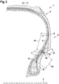
- a tire 1 according to the invention is shown schematically in a radial sectional view according to a further embodiment.
- the electromagnetic transmitting and receiving device 7 has a rubber jacket 18.
- the rubber casing 18 is in particular a component of the electromagnetic transmitting and receiving device 7.
- Electrical and electronic components 24 are arranged within the rubber casing 18. These components 24 and the rubber jacket 18 form the electromagnetic transmitting and receiving device 7
- a minimum distance 19 from the rubber jacket 18 to the first end point 11 is at least 5 mm and a minimum distance 20 from the rubber jacket 18 to the second end point 12 is at least 5 mm.
Landscapes
- Engineering & Computer Science (AREA)
- Mechanical Engineering (AREA)
- Computer Hardware Design (AREA)
- Microelectronics & Electronic Packaging (AREA)
- Physics & Mathematics (AREA)
- General Physics & Mathematics (AREA)
- Theoretical Computer Science (AREA)
- Tires In General (AREA)
Abstract
Description
- Die Erfindung bezieht sich auf einen Reifen.
Die Erfindung geht aus von einem Reifen. Der Reifen ist um eine Rotationsachse in eine Umlaufrichtung rotierbar und weist eine Karkasseinlage, einen Schulterbereich, einen Seitenwandbereich und eine elektromagnetische Sende- und Empfangsvorrichtung auf.
Die Karkasseinlage grenzt an den Seitenwandbereich an. Der Seitenwandbereich weist eine Verstärkungskomponente, eine erste Seitenwandkomponente und eine zweite Seitenwandkomponente auf. Die zweite Seitenwandkomponente kann auch als Rimstripkomponente bezeichnet werden.
Die erste Seitenwandkomponente und die zweite Seitenwandkomponente bilden einen Seitenwandkomponentenbereich. - Bei der elektromagnetischen Sende- und Empfangsvorrichtung handelt es sich insbesondere um eine RFID-Vorrichtung. RFID steht für Radio Frequency Identification und bedeutet Identifizierung mit Hilfe elektromagnetischer Wellen. Elektromagnetisch bedeutet elektromagnetisch wirkend. Das bedeutet, dass die elektromagnetische Sende- und Empfangsvorrichtung eingerichtet ist, elektromagnetische Signale zu senden und zu empfangen.
- Die Verstärkungskomponente ist insbesondere aus einer Kautschukmischung ausgebildet. Die Verstärkungskomponente verstärkt den Seitenwandbereich und stellt somit die Einsatzfähigkeit des Reifens sicher.
Aus dem Stand der Technik sind Reifen bekannt, die elektromagnetische Sende- und Empfangsvorrichtungen aufweisen. Beispielsweise wird in derEP2223814B1 eine elektromagnetische Sende- und Empfangsvorrichtung für einen Reifen offenbart. - Bei den aus dem Stand der Technik bekannten Reifen könnte eine Anordnung einer elektromagnetischen Sende- und Empfangsvorrichtung innerhalb des Reifens nicht optimal ausgestaltet sein. So könnte die elektromagnetische Sende- und Empfangsvorrichtung in einem solchen Bereich des Reifens angeordnet sein, in dem sie höheren mechanischen Belastungen ausgesetzt sein könnte als in anderen Bereichen des Reifens.
Der Erfindung liegt daher die Aufgabe zugrunde einen Reifen bereitzustellen, bei dem die Anordnung der elektromagnetischen Sende- und Empfangsvorrichtung innerhalb des Reifens verbessert wird.
Gelöst wird die erfindungsgemäße Aufgabe dadurch, dass die elektromagnetische Sende- und Empfangsvorrichtung zwischen der Verstärkungskomponente und dem Seitenwandkomponentenbereich angeordnet ist. - Durch den erfindungsgemäßen Umstand, wonach die elektromagnetische Sende- und Empfangsvorrichtung zwischen der Verstärkungskomponente und dem Seitenwandkomponentenbereich angeordnet ist, wird die elektromagnetische Sende- und Empfangsvorrichtung in einem solchen Bereich des Reifens angeordnet, in dem sie in einer ausreichenden räumlichen Nähe zu der Verstärkungskomponente des Reifens angeordnet ist. Durch diese Nähe zu der Verstärkungskomponente kann die elektromagnetische Sende- und Empfangsvorrichtung vor mechanischen Belastungen besser geschützt werden, als es in anderen Bereichen des Reifens der Fall wäre.
Somit wird ein verbesserter Reifen bereitgestellt.
Bei dem Reifen handelt es sich insbesondere um einen Lkw-Reifen, um einen Pkw-Reifen oder um einen Fahrrad-Reifen oder um einen Motorrad-Reifen. - Weitere vorteilhafte Ausgestaltungsformen der vorliegenden Erfindung sind Gegenstand der Unteransprüche.
Gemäß einer vorzugsweisen Ausgestaltungsform der vorliegenden Erfindung ist die elektromagnetische Sende- und Empfangsvorrichtung zwischen der Verstärkungskomponente und der ersten Seitenwandkomponente angeordnet oder zwischen der Verstärkungskomponente und der zweiten Seitenwandkomponente angeordnet. - Gemäß einer nächsten vorzugsweisen Ausgestaltungsform der vorliegenden Erfindung steht die elektromagnetische Sende- und Empfangsvorrichtung in direktem Kontakt mit der Verstärkungskomponente und ist insbesondere stoffschlüssig mit der Verstärkungskomponente verbunden.
- Gemäß einer nächsten vorzugsweisen Ausgestaltungsform der vorliegenden Erfindung weist die Verstärkungskomponente einen ersten Endpunkt und einen zweiten Endpunkt auf. Der erste Endpunkt liegt in einer radialen Richtung von der Rotationsachse am weitesten entfernt und der zweite Endpunkt liegt in der radialen Richtung der Rotationsachse am nächsten. Ein radialer Abstand eines ersten Oberflächenpunktes der elektromagnetischen Sende- und Empfangsvorrichtung, der zur Rotationsachse in der radialen Richtung nächstgelegen ist, ist zu der Rotationsachse mindestens 2 mm größer, als ein radialer Abstand des zweiten Endpunktes zur Rotationsachse. Ein radialer Abstand des ersten Endpunktes zu der Rotationsachse ist mindestens 2 mm größer, als ein radialer Abstand zu der Rotationsachse eines zweiten Oberflächenpunktes der elektromagnetischen Sende- und Empfangsvorrichtung, der von der Rotationsachse am weitesten entfernt liegt.
Der Reifen folgt grundsätzlich einer Form eines Kreises. Ein radialer Abstand oder eine radiale Richtung erstrecken sich parallel zu einem Radius des Kreises dessen Form der Reifen grundsätzlich folgt. Der Radius liegt rechtwinklig zur Rotationsachse und zur Umlaufrichtung. Ein radialer Abstand ist stets ein Abstand bis zur Rotationsachse.
Auch die Verstärkungskomponente folgt einer Kreisform.
Durch den erfindungsgemäßen Umstand, wonach die Verstärkungskomponente einen ersten Endpunkt und einen zweiten Endpunkt aufweist, wobei der erste Endpunkt in einer radialen Richtung von der Rotationsachse am weitesten entfernt liegt und wobei der zweite Endpunkt in der radialen Richtung der Rotationsachse am nächsten liegt, wobei ein radialer Abstand eines ersten Oberflächenpunktes der elektromagnetischen Sende- und Empfangsvorrichtung, der zur Rotationsachse in der radialen Richtung nächstgelegen ist, zu der Rotationsachse mindestens 2 mm größer ist, als ein radialer Abstand des zweiten Endpunktes zur Rotationsachse, und, wonach ein radialer Abstand des ersten Endpunktes zu der Rotationsachse mindestens 2 mm größer ist, als ein radialer Abstand zu der Rotationsachse eines zweiten Oberflächenpunktes der elektromagnetischen Sende- und Empfangsvorrichtung, der von der Rotationsachse am weitesten entfernt liegt, werden insbesondere mechanische Belastungen der elektromagnetischen Sende- und Empfangsvorrichtung, die an den Endpunkten der Verstärkungsvorrichtung auftreten könnten, vermieden. - Gemäß einer nächsten vorzugsweisen Ausgestaltungsform der vorliegenden Erfindung weist die elektromagnetische Sende- und Empfangsvorrichtung eine Gummiummantelung auf. Dabei ist die Gummiummantelung insbesondere Bestandteil der elektromagnetischen Sende- und Empfangsvorrichtung.
Innerhalb der Gummiummantelung sind elektronische und elektrische Komponenten der elektromagnetischen Sende- und Empfangsvorrichtung angeordnet. Der erste Oberflächenpunkt der elektromagnetischen Sende- und Empfangsvorrichtung liegt dann auf der Oberfläche der Gummiummantelung. Die Oberfläche der Gummiummantelung ist eine von der elektromagnetischen Sende- und Empfangsvorrichtung weg orientierte Außenfläche. Die Gummiummantelung ist insbesondere quaderförmig oder ellipsoid ausgebildet, wobei insbesondere eine maximale Dicke der elektromagnetischen Sende- und Empfangsvorrichtung von 2 mm, eine dazu rechtwinklig sich erstreckende maximale Länge der elektromagnetischen Sende- und Empfangsvorrichtung von 80 mm und eine sich zu Dicke und Länge rechtwinklig erstreckende maximale Breite der elektromagnetischen Sende- und Empfangsvorrichtung von 20 mm nicht überschritten wird. Die elektronischen und elektrischen Komponenten der elektromagnetischen Sende- und Empfangsvorrichtung weisen insbesondere zusammen eine maximale räumliche Erstreckung von höchstens 70 mm auf. Die Antenne oder die Antennen der elektromagnetischen Sende- und Empfangsvorrichtung weist beziehungsweise weisen insbesondere für den Fall, wonach die Antenne beziehungsweise die Antennen einer Helixform folgt beziehungsweise folgen, einen Außendurchmesser von höchstens 2 mm auf. - Die elektromagnetische Sende- und Empfangsvorrichtung weist gemäß einer vorteilhaften Ausführungsform der Erfindung insbesondere eine oder zwei Antennen auf. Die Antenne beziehungsweise die zwei Antennen sind insbesondere helixförmig.
- Durch den erfindungsgemäßen Umstand, wonach die elektromagnetische Sende- und Empfangsvorrichtung eine Gummiummantelung aufweist, wobei die Gummiummantelung insbesondere Bestandteil der elektromagnetische Sende- und Empfangsvorrichtung ist, wird eine homogene Umgebung geschaffen, die eine elektromagnetische Abstimmung der elektromagnetischen Sende- und Empfangsvorrichtung auf ihre Umgebung erleichtert.
Gemäß einer nächsten vorzugsweisen Ausgestaltungsform der vorliegenden Erfindung beträgt ein minimaler Abstand der Gummiummantelung zu dem ersten Endpunkt mindestens 5 mm und insbesondere mindestens 0,1 mm bis mindestens 5 mm.
Durch den erfindungsgemäßen Umstand, wonach ein minimaler Abstand der Gummiummantelung zu dem ersten Endpunkt mindestens 5 mm beträgt, werden insbesondere mechanische Belastungen der Gummiummantelung, die an dem ersten Endpunkt auftreten könnten, vermieden. - Gemäß einer nächsten vorzugsweisen Ausgestaltungsform der vorliegenden Erfindung beträgt ein minimaler Abstand der Gummiummantelung zu dem zweiten Endpunkt mindestens 5 mm und insbesondere mindestens 0,1 mm bis mindestens 5 mm.
- Durch den erfindungsgemäßen Umstand, wonach ein minimaler Abstand der Gummiummantelung zu dem zweiten Endpunkt mindestens 5 mm beträgt, werden insbesondere mechanische Belastungen der Gummiummantelung, die an dem zweiten Endpunkt auftreten könnten, vermieden.
- Weitere Merkmale, Vorteile und Einzelheiten, auf die die Erfindung in ihrem Umfang aber nicht beschränkt ist, werden nun anhand der Zeichnungen näher beschrieben.
- Es zeigt:
-
Fig. 1 : Eine schematische Darstellung eines erfindungsgemäßen Reifens in Radialschnittansicht; -
Fig. 2 : Eine schematische Darstellung eines erfindungsgemäßen Reifens gemäß einer weiteren Ausführungsform in Radialschnittansicht; -
Fig. 3 : Eine schematische Darstellung eines erfindungsgemäßen Reifens gemäß einer weiteren Ausführungsform in Radialschnittansicht. - In der
Figur 1 ist ein erfindungsgemäßer Reifen 1 schematisch in Radialschnittansicht dargestellt. Der Reifen 1 ist um eine Rotationsachse 2 in eine Umlaufrichtung 3 rotierbar.
Der Reifen 1 weist eine Karkasseinlage 4, einen Schulterbereich 5, einen Seitenwandbereich 6 und eine elektromagnetische Sende- und Empfangsvorrichtung 7 auf. Die Karkasseinlage 4 grenzt an den Seitenwandbereich 6 an. Der Seitenwandbereich 6 weist eine Verstärkungskomponente 8, eine erste Seitenwandkomponente 9 und eine zweite Seitenwandkomponente 10 auf, wobei die erste Seitenwandkomponente 9 und die zweite Seitenwandkomponente 10 einen Seitenwandkomponentenbereich 21 bilden.
Die elektromagnetische Sende- und Empfangsvorrichtung 7 ist zwischen der Verstärkungskomponente 8 und dem Seitenwandkomponentenbereich 21 angeordnet.
Ferner steht gemäß der in derFigur 1 dargestellten Ausführungsform des erfindungsgemäßen Reifens 1 die elektromagnetische Sende- und Empfangsvorrichtung 7 in direktem Kontakt mit der Verstärkungskomponente 8 und ist insbesondere stoffschlüssig mit der Verstärkungskomponente 8 verbunden. - In der
Figur 2 ist ein erfindungsgemäßer Reifen 1 in Radialschnittansicht gemäß einer weiteren Ausführungsform schematisch dargestellt. Gemäß der Darstellung der in derFigur 2 dargestellten Ausführungsform weist die Verstärkungskomponente 8 einen ersten Endpunkt 11 und einen zweiten Endpunkt 12 auf, wobei der erste Endpunkt 11 in einer radialen Richtung 13 von der Rotationsachse 2 am weitesten entfernt liegt und wobei der zweite Endpunkt 12 in der radialen Richtung 13 der Rotationsachse 2 am nächsten liegt, wobei ein radialer Abstand 14 eines ersten Oberflächenpunktes 15 der elektromagnetischen Sende- und Empfangsvorrichtung 7, der zur Rotationsachse 2 in der radialen Richtung 13 nächstgelegen ist, zu der Rotationsachse 2 mindestens 2 mm größer ist, als ein radialer Abstand 16 des zweiten Endpunktes 12 zur Rotationsachse 2, und, wobei ein radialer Abstand 17 des ersten Endpunktes 11 zu der Rotationsachse 2 mindestens 2 mm größer ist, als ein radialer Abstand 23 zu der Rotationsachse 2 eines zweiten Oberflächenpunktes 22 der elektromagnetischen Sende- und Empfangsvorrichtung 7, der von der Rotationsachse 2 am weitesten entfernt liegt. - In der
Figur 3 ist ein erfindungsgemäßer Reifen 1 in Radialschnittansicht gemäß einer weiteren Ausführungsform schematisch dargestellt. Gemäß der Darstellung in derFigur 3 weist die elektromagnetische Sende- und Empfangsvorrichtung 7 eine Gummiummantelung 18 auf. Die Gummiummantelung 18 ist insbesondere Bestandteil der elektromagnetischen Sende- und Empfangsvorrichtung 7. Innerhalb der Gummiummantelung 18 sind elektrische und elektronische Komponenten 24 angeordnet. Diese Komponenten 24 und die Gummiummantelung 18 bilden die elektromagnetische Sende- und Empfangsvorrichtung 7 - Insbesondere beträgt ein minimaler Abstand 19 der Gummiummantelung 18 zu dem ersten Endpunkt 11 mindestens 5 mm und ein minimaler Abstand 20 der Gummiummantelung 18 zu dem zweiten Endpunkt 12 beträgt mindestens 5 mm.
-
- 1
- Reifen
- 2
- Rotationsachse
- 3
- Umlaufrichtung
- 4
- Karkasseinlage
- 5
- Schulterbereich
- 6
- Seitenwandbereich
- 7
- Elektromagnetische Sende- und Empfangsvorrichtung
- 8
- Verstärkungskomponente
- 9
- Erste Seitenwandkomponente
- 10
- Zweite Seitenwandkomponente
- 11
- Erster Endpunkt
- 12
- Zweiter Endpunkt
- 13
- Radiale Richtung
- 14
- Radialer Abstand
- 15
- Erster Oberflächenpunkt
- 16
- Radialer Abstand
- 17
- Radialer Abstand
- 18
- Gummiummantelung
- 19
- Minimaler Abstand
- 20
- Minimaler Abstand
- 21
- Seitenwandkomponentenbereich
- 22
- Zweiter Oberflächenpunkt
- 23
- Radialer Abstand
- 24
- Elektrische und elektronische Komponenten
Claims (6)
- Reifen (1), wobei der Reifen (1) um eine Rotationsachse (2) in eine Umlaufrichtung (3) rotierbar ist, aufweisend eine Karkasseinlage (4), einen Schulterbereich (5), einen Seitenwandbereich (6) und eine elektromagnetische Sende- und Empfangsvorrichtung (7), wobei die Karkasseinlage (4) an den Seitenwandbereich (6) angrenzt und der Seitenwandbereich (6) eine Verstärkungskomponente (8), eine erste Seitenwandkomponente (9) und eine zweite Seitenwandkomponente (10) aufweist, wobei die erste Seitenwandkomponente (9) und die zweite Seitenwandkomponente (10) einen Seitenwandkomponentenbereich (21) bilden, dadurch gekennzeichnet, dass die elektromagnetische Sende- und Empfangsvorrichtung (7) zwischen der Verstärkungskomponente (8) und dem Seitenwandkomponentenbereich (21) angeordnet ist.
- Reifen (1) nach Anspruch 1, dadurch gekennzeichnet, dass die elektromagnetische Sende- und Empfangsvorrichtung (7) zwischen der Verstärkungskomponente (8) und der ersten Seitenwandkomponente (9) angeordnet ist oder zwischen der Verstärkungskomponente (8) und der zweiten Seitenwandkomponente (10) angeordnet ist.
- Reifen (1) nach einem der vorhergehenden Ansprüche, dadurch gekennzeichnet, dass die elektromagnetische Sende- und Empfangsvorrichtung (7) in direktem Kontakt mit der Verstärkungskomponente (8) steht und insbesondere stoffschlüssig mit der Verstärkungskomponente (8) verbunden ist.
- Reifen (1) nach einem der vorhergehenden Ansprüche, dadurch gekennzeichnet, dass die Verstärkungskomponente (8) einen ersten Endpunkt (11) und einen zweiten Endpunkt (12) aufweist, wobei der erste Endpunkt (11) in einer radialen Richtung (13) von der Rotationsachse (2) am weitesten entfernt liegt und wobei der zweite Endpunkt (12) in der radialen Richtung (13) der Rotationsachse (2) am nächsten liegt, wobei ein radialer Abstand (14) eines ersten Oberflächenpunktes (15) der elektromagnetischen Sende- und Empfangsvorrichtung (7), der zur Rotationsachse (2) in der radialen Richtung (13) nächstgelegen ist, zu der Rotationsachse (2) mindestens 2 mm größer ist, als ein radialer Abstand (16) des zweiten Endpunktes (12) zur Rotationsachse (2), und, dass ein radialer Abstand (17) des ersten Endpunktes (11) zu der Rotationsachse (2) mindestens 2 mm größer ist, als ein radialer Abstand (23) zu der Rotationsachse (2) eines zweiten Oberflächenpunktes (22) der elektromagnetischen Sende- und Empfangsvorrichtung (7), der von der Rotationsachse (2) am weitesten entfernt liegt.
- Reifen (1) nach einem der vorhergehenden Ansprüche, dadurch gekennzeichnet, dass die elektromagnetische Sende- und Empfangsvorrichtung (7) eine Gummiummantelung (18) aufweist, wobei die Gummiummantelung (18) insbesondere Bestandteil der elektromagnetische Sende- und Empfangsvorrichtung (7) ist.
- Reifen (1) nach dem vorhergehenden Anspruch, dadurch gekennzeichnet, dass ein minimaler Abstand (19) der Gummiummantelung (18) zu dem ersten Endpunkt (11) mindestens 5 mm beträgt und/oder dass ein minimaler Abstand (20) der Gummiummantelung (18) zu dem zweiten Endpunkt (12) mindestens 5 mm beträgt.
Applications Claiming Priority (1)
| Application Number | Priority Date | Filing Date | Title |
|---|---|---|---|
| DE102019209779.0A DE102019209779A1 (de) | 2019-07-03 | 2019-07-03 | Reifen |
Publications (1)
| Publication Number | Publication Date |
|---|---|
| EP3760456A1 true EP3760456A1 (de) | 2021-01-06 |
Family
ID=70977845
Family Applications (1)
| Application Number | Title | Priority Date | Filing Date |
|---|---|---|---|
| EP20178322.2A Withdrawn EP3760456A1 (de) | 2019-07-03 | 2020-06-04 | Reifen |
Country Status (2)
| Country | Link |
|---|---|
| EP (1) | EP3760456A1 (de) |
| DE (1) | DE102019209779A1 (de) |
Cited By (2)
| Publication number | Priority date | Publication date | Assignee | Title |
|---|---|---|---|---|
| EP4296091A1 (de) * | 2022-06-24 | 2023-12-27 | Sumitomo Rubber Industries, Ltd. | Schwerlastreifen |
| CN117412871A (zh) * | 2021-06-30 | 2024-01-16 | 株式会社普利司通 | 轮胎 |
Families Citing this family (1)
| Publication number | Priority date | Publication date | Assignee | Title |
|---|---|---|---|---|
| JP2025042075A (ja) * | 2023-09-14 | 2025-03-27 | 住友ゴム工業株式会社 | 重荷重用タイヤ |
Citations (10)
| Publication number | Priority date | Publication date | Assignee | Title |
|---|---|---|---|---|
| US20080289736A1 (en) * | 2007-04-03 | 2008-11-27 | Michelin Recherche Et Technique S.A. | Tire including an electronic member, and a method of fabricating such a tire |
| KR20100120505A (ko) * | 2009-05-06 | 2010-11-16 | 금호타이어 주식회사 | Rfid 태그 매설 타이어 |
| WO2015088890A1 (en) * | 2013-12-13 | 2015-06-18 | Bridgestone Americas Tire Operations, Llc | Tire having an electronic device in a lower sidewall |
| EP2223814B1 (de) | 2009-02-25 | 2017-05-17 | The Goodyear Tire & Rubber Company | Umgebungsbeständige Anordnung mit einer elektronischen Vorrichtung zur Verwendung in einem Reifen |
| EP3196056A1 (de) * | 2014-08-08 | 2017-07-26 | Bridgestone Corporation | Reifen |
| WO2018104623A1 (fr) * | 2016-12-07 | 2018-06-14 | Compagnie Generale Des Etablissements Michelin | Pneumatique adapte pour roulage a plat equipe d'un organe electronique |
| WO2018104619A1 (fr) * | 2016-12-05 | 2018-06-14 | Compagnie Generale Des Etablissements Michelin | Enveloppe pneumatique équipée d'un organe électronique |
| WO2019054226A1 (ja) * | 2017-09-12 | 2019-03-21 | 住友ゴム工業株式会社 | 空気入りタイヤ |
| WO2019180358A1 (fr) * | 2018-03-22 | 2019-09-26 | Compagnie Generale Des Etablissements Michelin | Pneumatique poids-lourd equipe d'un module de communication radiofrequence |
| EP3549796A1 (de) * | 2018-04-03 | 2019-10-09 | Hankook Tire Co., Ltd. | Reifen mit rfid-system |
-
2019
- 2019-07-03 DE DE102019209779.0A patent/DE102019209779A1/de active Pending
-
2020
- 2020-06-04 EP EP20178322.2A patent/EP3760456A1/de not_active Withdrawn
Patent Citations (10)
| Publication number | Priority date | Publication date | Assignee | Title |
|---|---|---|---|---|
| US20080289736A1 (en) * | 2007-04-03 | 2008-11-27 | Michelin Recherche Et Technique S.A. | Tire including an electronic member, and a method of fabricating such a tire |
| EP2223814B1 (de) | 2009-02-25 | 2017-05-17 | The Goodyear Tire & Rubber Company | Umgebungsbeständige Anordnung mit einer elektronischen Vorrichtung zur Verwendung in einem Reifen |
| KR20100120505A (ko) * | 2009-05-06 | 2010-11-16 | 금호타이어 주식회사 | Rfid 태그 매설 타이어 |
| WO2015088890A1 (en) * | 2013-12-13 | 2015-06-18 | Bridgestone Americas Tire Operations, Llc | Tire having an electronic device in a lower sidewall |
| EP3196056A1 (de) * | 2014-08-08 | 2017-07-26 | Bridgestone Corporation | Reifen |
| WO2018104619A1 (fr) * | 2016-12-05 | 2018-06-14 | Compagnie Generale Des Etablissements Michelin | Enveloppe pneumatique équipée d'un organe électronique |
| WO2018104623A1 (fr) * | 2016-12-07 | 2018-06-14 | Compagnie Generale Des Etablissements Michelin | Pneumatique adapte pour roulage a plat equipe d'un organe electronique |
| WO2019054226A1 (ja) * | 2017-09-12 | 2019-03-21 | 住友ゴム工業株式会社 | 空気入りタイヤ |
| WO2019180358A1 (fr) * | 2018-03-22 | 2019-09-26 | Compagnie Generale Des Etablissements Michelin | Pneumatique poids-lourd equipe d'un module de communication radiofrequence |
| EP3549796A1 (de) * | 2018-04-03 | 2019-10-09 | Hankook Tire Co., Ltd. | Reifen mit rfid-system |
Cited By (3)
| Publication number | Priority date | Publication date | Assignee | Title |
|---|---|---|---|---|
| CN117412871A (zh) * | 2021-06-30 | 2024-01-16 | 株式会社普利司通 | 轮胎 |
| EP4364962A4 (de) * | 2021-06-30 | 2024-10-23 | Bridgestone Corporation | Reifen |
| EP4296091A1 (de) * | 2022-06-24 | 2023-12-27 | Sumitomo Rubber Industries, Ltd. | Schwerlastreifen |
Also Published As
| Publication number | Publication date |
|---|---|
| DE102019209779A1 (de) | 2021-01-07 |
Similar Documents
| Publication | Publication Date | Title |
|---|---|---|
| EP3760456A1 (de) | Reifen | |
| DE102014112868B3 (de) | Bremsbacke mit Verschleißanzeiger | |
| EP1366931B1 (de) | Transponder zum Einbau in oder auf die Oberfläche von Gegenständen | |
| EP2981980B1 (de) | Induktive ladeeinrichtung, elektrofahrzeug, ladestation und verfahren zum induktiven laden | |
| EP3887176B1 (de) | Fahrzeugreifen | |
| EP3578395B1 (de) | Elektromagnetische sende- und empfangsvorrichtung | |
| DE112011104017T5 (de) | Reifen ausgestattet mit einem Informationsbeschaffungsgerät | |
| EP3798020B1 (de) | Reifen | |
| DE19915999C2 (de) | Kraftfahrzeug mit Reifendruckkontrollsystem | |
| EP3739519B1 (de) | Reifen | |
| EP3969297B1 (de) | Reifen | |
| EP2618425B1 (de) | Antennenabdeckung | |
| EP3953189B1 (de) | Reifen | |
| WO2018224193A1 (de) | Elektromagnetische sende- und empfangsvorrichtung für einen reifen | |
| DE2855721C2 (de) | Antwortgerät für eins System zum selbsttätigen drahtlosen Übertragen von mehrstelligen numerischen Informationen zwischen gegeneinander bewegbaren aktiven Abfragegeräten und passiven Antwortgeräten | |
| DE102019207021A1 (de) | Reifen | |
| DE102012108600B3 (de) | Antennenanordnung mit flachbauendem Antennenelement | |
| DE102011084592A1 (de) | Kombination eines Radar- und Antennenkopfes | |
| EP3808577B1 (de) | Reifen | |
| EP3281258A1 (de) | Elektronisches steuergerät | |
| EP3918522B1 (de) | Elektromagnetisch wirkende sende- und empfangsvorrichtung | |
| EP3174741B1 (de) | Antenne für einen empfänger oder sender in einem kraftfahrzeug, insbesondere für ein reifenzustandsüberwachungssystem | |
| DE102018200104A1 (de) | Sicherheitssystem | |
| DE102010020017B4 (de) | Kopplungsstruktur für eine Antennenanordnung | |
| WO2017081282A1 (de) | Vorrichtung zur erfassung einer drehbewegung |
Legal Events
| Date | Code | Title | Description |
|---|---|---|---|
| PUAI | Public reference made under article 153(3) epc to a published international application that has entered the european phase |
Free format text: ORIGINAL CODE: 0009012 |
|
| STAA | Information on the status of an ep patent application or granted ep patent |
Free format text: STATUS: THE APPLICATION HAS BEEN PUBLISHED |
|
| AK | Designated contracting states |
Kind code of ref document: A1 Designated state(s): AL AT BE BG CH CY CZ DE DK EE ES FI FR GB GR HR HU IE IS IT LI LT LU LV MC MK MT NL NO PL PT RO RS SE SI SK SM TR |
|
| AX | Request for extension of the european patent |
Extension state: BA ME |
|
| STAA | Information on the status of an ep patent application or granted ep patent |
Free format text: STATUS: REQUEST FOR EXAMINATION WAS MADE |
|
| 17P | Request for examination filed |
Effective date: 20210706 |
|
| RBV | Designated contracting states (corrected) |
Designated state(s): AL AT BE BG CH CY CZ DE DK EE ES FI FR GB GR HR HU IE IS IT LI LT LU LV MC MK MT NL NO PL PT RO RS SE SI SK SM TR |
|
| STAA | Information on the status of an ep patent application or granted ep patent |
Free format text: STATUS: EXAMINATION IS IN PROGRESS |
|
| 17Q | First examination report despatched |
Effective date: 20211006 |
|
| STAA | Information on the status of an ep patent application or granted ep patent |
Free format text: STATUS: THE APPLICATION IS DEEMED TO BE WITHDRAWN |
|
| 18D | Application deemed to be withdrawn |
Effective date: 20220217 |