WO2019054253A1 - Prétensionneur et dispositif de ceinture de sécurité - Google Patents
Prétensionneur et dispositif de ceinture de sécurité Download PDFInfo
- Publication number
- WO2019054253A1 WO2019054253A1 PCT/JP2018/032901 JP2018032901W WO2019054253A1 WO 2019054253 A1 WO2019054253 A1 WO 2019054253A1 JP 2018032901 W JP2018032901 W JP 2018032901W WO 2019054253 A1 WO2019054253 A1 WO 2019054253A1
- Authority
- WO
- WIPO (PCT)
- Prior art keywords
- piston
- wire
- webbing
- pretensioner
- housing
- Prior art date
- Legal status (The legal status is an assumption and is not a legal conclusion. Google has not performed a legal analysis and makes no representation as to the accuracy of the status listed.)
- Ceased
Links
Images


Classifications
-
- B—PERFORMING OPERATIONS; TRANSPORTING
- B60—VEHICLES IN GENERAL
- B60R—VEHICLES, VEHICLE FITTINGS, OR VEHICLE PARTS, NOT OTHERWISE PROVIDED FOR
- B60R22/00—Safety belts or body harnesses in vehicles
- B60R22/34—Belt retractors, e.g. reels
- B60R22/46—Reels with means to tension the belt in an emergency by forced winding up
- B60R22/4619—Transmission of tensioning power by cable, e.g. using a clutch on reel side
-
- B—PERFORMING OPERATIONS; TRANSPORTING
- B60—VEHICLES IN GENERAL
- B60R—VEHICLES, VEHICLE FITTINGS, OR VEHICLE PARTS, NOT OTHERWISE PROVIDED FOR
- B60R22/00—Safety belts or body harnesses in vehicles
- B60R22/18—Anchoring devices
- B60R22/195—Anchoring devices with means to tension the belt in an emergency, e.g. means of the through-anchor or splitted reel type
- B60R22/1952—Transmission of tensioning power by cable; Return motion locking means therefor
-
- B—PERFORMING OPERATIONS; TRANSPORTING
- B60—VEHICLES IN GENERAL
- B60R—VEHICLES, VEHICLE FITTINGS, OR VEHICLE PARTS, NOT OTHERWISE PROVIDED FOR
- B60R22/00—Safety belts or body harnesses in vehicles
- B60R22/18—Anchoring devices
- B60R22/195—Anchoring devices with means to tension the belt in an emergency, e.g. means of the through-anchor or splitted reel type
- B60R22/1954—Anchoring devices with means to tension the belt in an emergency, e.g. means of the through-anchor or splitted reel type characterised by fluid actuators, e.g. pyrotechnic gas generators
- B60R22/1955—Linear actuators
-
- B—PERFORMING OPERATIONS; TRANSPORTING
- B60—VEHICLES IN GENERAL
- B60R—VEHICLES, VEHICLE FITTINGS, OR VEHICLE PARTS, NOT OTHERWISE PROVIDED FOR
- B60R22/00—Safety belts or body harnesses in vehicles
- B60R22/34—Belt retractors, e.g. reels
- B60R22/46—Reels with means to tension the belt in an emergency by forced winding up
- B60R22/4628—Reels with means to tension the belt in an emergency by forced winding up characterised by fluid actuators, e.g. pyrotechnic gas generators
Definitions
- the present disclosure relates to a pretensioner and a seat belt device.
- a configuration is proposed in which a pretensioner is provided which pulls in the webbing that restrains the vehicle occupant at the time of a vehicle collision to increase the restraining force of the occupant by the webbing.
- a pretensioner for example, in Patent Document 1, a wire whose one end is connected to the webbing, a piston connected to the other end of the wire, a cylinder which slidably accommodates the piston, and a piston which operates in a direction to draw the wire And a gas generator for supplying the gas to the piston through a gas chamber in the housing.
- the drawing speed of the webbing by the pretensioner is determined by the pressure of the gas supplied from the gas generator to the piston.
- the gas generator since the gas generator mainly generates gas by the explosive, the pressure of the gas is adjusted by adjusting the type and dose of the explosive. However, it took time and cost to adjust drug types and doses.
- An object of the present disclosure is to provide a pretensioner and a seat belt device capable of easily adjusting gas pressure.
- a pretensioner includes a wire whose one end is connected to a webbing for restraining a vehicle occupant, a piston connected to the other end of the wire, and the piston A cylinder slidably housed, a housing for penetrating the wire and holding the cylinder, and a gas for operating the piston in a direction to draw the wire are supplied to the piston through a gas chamber in the housing
- the piston has a cylindrical portion extending in the axial direction of the piston at one end on the gas chamber side, and the gas chamber is adjusted by adjusting the volume of the internal space of the cylindrical portion Adjust the initial volume of
- a seat belt device is connected to a webbing for restraining an occupant of a vehicle and the webbing, and the webbing is pulled in at the time of a vehicle collision to improve the occupant's restraint performance by the webbing. And the above-mentioned pretensioner.
- FIG. 1 It is a block diagram of the seat belt device concerning one embodiment of the present invention. It is an exploded perspective view of a pretensioner concerning one embodiment of the present invention. It is a longitudinal cross-sectional view of a pre-tensioner. It is an enlarged view of the vicinity of the gas chamber in FIG. It is the perspective view which looked the piston from the housing side (x negative direction side). It is sectional drawing which shows the modification of the shape of the internal space of the cylindrical part of a piston. It is a figure which shows the effect
- the x direction, the y direction, and the z direction are directions perpendicular to one another, the x direction and the y direction are horizontal directions, and the z direction is a vertical direction.
- the x direction is the sliding direction of the piston 3 and the direction in which the webbing 101 is pulled in is the x positive direction.
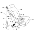
- FIG. 1 is a block diagram of a seat belt device 100 according to an embodiment of the present invention.
- FIG. 1 shows an example of a state where the seat belt device 100 is mounted on a vehicle.
- the seat belt device 100 includes a webbing 101, a retractor 102, a tongue 105, a buckle 107, and a pretensioner 1.
- the webbing 101 is a belt-like member for restraining an occupant sitting on the seat 108.
- One end 103 of the webbing 101 is connected to the retractor 102, and the other end 106 of the webbing 101 is connected to the pretensioner 1.
- the retractor 102 is a winding device that enables the webbing 101 to be wound up or pulled out, and the webbing 101 is pulled out from the main body of the retractor 102 when an acceleration equal to or greater than a predetermined value at the time of a vehicle collision or the like is detected.
- the retractor 102 is fixed to a lateral vehicle body portion (for example, a lower portion of a pillar to which the shoulder anchor 104 is fixed) of the seatback 108 of the seat 108.
- the tongue 105 is a plate-like member slidably attached to the webbing 101 between the pretensioner 1 and the shoulder anchor 104.
- the buckle 107 is a member to which the tongue 105 is attached and detached.
- the buckle 107 is fixed to the seat portion opposite to the retractor 102 with the seat portion 110 of the seat 108 interposed therebetween.
- the chest of the occupant on the seat 108 is restrained by the shoulder belt portion 101 b of the webbing 101, and the waist of the occupant is restrained by the lap belt portion 101 a of the webbing 101.
- the shoulder belt portion 101 b is a portion of the webbing 101 between the shoulder anchor 104 and the tongue 105
- the lap belt portion 101 a is a portion of the webbing 101 between the tongue 105 and the pretensioner 1.
- the pretensioner 1 instantly pulls in the lap belt portion 101a of the webbing 101 when an acceleration equal to or greater than a predetermined value at the time of a vehicle collision or the like is detected, thereby providing slack between the occupant's waist and the lap belt portion 101a. It is a wrap pretensioner to reduce.
- the pretensioner 1 is usually fixed to a vehicle body portion near the door with respect to the side portion on the vehicle outside of the seat portion 110.
- FIG. 2 is an exploded perspective view of the pretensioner 1 according to an embodiment of the present invention.
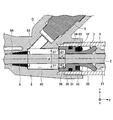
- FIG. 3 is a longitudinal sectional view of the pretensioner 1.
- FIG. 4 is an enlarged view of the vicinity of the gas chamber in FIG.
- the pretensioner 1 includes a wire 2 connected to a webbing 101 for restraining an occupant, a piston 3 disposed on the wire 2, and a cylinder 4 slidably accommodating the piston 3. , A gas generator 5 for applying a driving force to the piston 3, a housing 6 integrally connecting the cylinder 4 and the gas generator 5, and a bracket 7 connected to the housing 6 for positioning the wire 2.
- the housing 6 includes an insertion hole 61 for guiding the wire 2, a communication portion 62 communicating with the cylinder 4 and the insertion hole 61, and a gas supply port 63 for supplying the gas generated by the gas generator 5 to the communication portion 62.
- the pretensioner 1 includes a wire guide 8 disposed at a boundary 66 between the insertion hole 61 and the communication portion 62.
- the pretensioner 1 has a function as a belt anchor, and is fixed to the vehicle body by inserting a bolt 9 into a fixing hole 7 a formed in the bracket 7 and a fixing hole 6 a formed in the housing 6.
- the bracket 7 includes a guide portion 7 b, and holds the bending angle of the wire 2 by inserting the wire 2 along the guide portion 7 b when the bracket 7 is integrally assembled to the housing 6.
- the holder 21 and the ferrule 22 are connected to one end of the wire 2.
- the ferrule 22 is connected to the end of the lap belt 101 a of the webbing 101.
- the other end of the wire 2 is inserted through the bracket 7 into the housing 6 and connected to the wire end 23 in the cylinder 4.
- a piston 3 is slidably disposed in the cylinder 4, and the wire 2 is connected to the wire end 23 after being inserted into the piston 3.
- An O-ring 31 is disposed on the outer periphery of the piston 3 to improve air tightness. Further, a ball 32 and a ball ring 33 are disposed in the middle part of the piston 3 for suppressing the reverse movement.
- the gas generator 5 is disposed in an opening (gas generator mounting portion 64) formed in the housing 6 and fixed to the housing 6, as shown in FIGS.
- a gas supply port 63 is constituted by a passage communicating the gas generator mounting portion 64 with the communication portion 62.
- the gas generator 5 is connected to, for example, an acceleration sensor (not shown) that detects a collision of a vehicle, and operates at the time of a vehicle collision to eject high pressure gas into the housing 6.
- the gas generator 5 generates a gas, for example, by a built-in explosive.
- the high pressure gas ejected into the housing 6 presses the piston 3 to move the piston 3 in a direction (x positive direction) away from the housing 6.
- the wire 2 is drawn into the housing 6 and the cylinder 4 to clamp the webbing 101 (lap belt 101a).
- the housing 6 is made of, for example, a material having a smaller specific gravity than iron (eg, aluminum, an aluminum alloy, etc.). Specifically, the housing 6 may be manufactured by aluminum die casting. By employing a material having a smaller specific gravity than iron, the weight of the housing 6 can be reduced.
- a material having a smaller specific gravity than iron eg, aluminum, an aluminum alloy, etc.
- the housing 6 also has an insertion hole 61 at one end side (x negative direction side) for guiding the wire 2 from the bracket 7 to the cylinder 4 and a connection part connecting the cylinder 4 at the other end side (x positive direction side) It has 65.
- the wire 2 is inserted into the insertion hole 61, and the screw portion of the cylinder 4 is screwed into the connection portion 65.
- a communication portion 62 communicating with the insertion hole 61 and the connection portion 65 is formed between the insertion hole 61 and the connection portion 65.
- connection portion 65 is larger than that of the communication portion 62, and thus a step is formed between the connection portion 65 and the communication portion 62. Further, the inner diameter of the cylinder 4 is formed larger than the communication portion 62. Therefore, when the piston 3 is disposed at the end of the cylinder 4 in the x negative direction, the end surface 37 of the piston 3 in the x negative direction abuts against the step, whereby the piston 3 in the x negative direction. Further movement is regulated. As shown in FIG. 4, this step protrudes to the center side from the inner peripheral surface of the cylinder 4 and functions as a stopper portion 67 that restricts the movement of the piston 3 to the housing 6 side (x negative direction side).
- An inner circumferential surface of the communication portion 62 on the insertion hole 61 side forms a conical surface whose diameter decreases as it approaches the insertion hole 61, and constitutes a boundary portion 66 between the insertion hole 61 and the communication portion 62. .
- the wire guide 8 made of resin is inserted into the boundary 66.
- the wire guide 8 has a substantially frusto-conical shape, and has a hole in the center portion through which the wire 2 can be inserted.
- the wire guide 8 has a function of guiding the wire 2 to the communication portion 62 and sealing the boundary portion 66.
- An opening communicating with the gas supply port 63 is formed in a part of the inner peripheral surface of the communication portion 62.
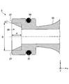
- FIG. 5 is a perspective view of the piston 3 as viewed from the housing 6 side (x negative direction side).
- the piston 3 is provided with a groove 34 on the outer peripheral surface for fitting with the O-ring 31.
- a tapered surface 35 is provided on the outer peripheral surface of the piston 3 in the x positive direction side from the groove 34.
- the tapered surface 35 is formed such that the outer diameter increases from one end side (x negative direction side) where the cylindrical portion 36 of the piston 3 is located to the other end side (x positive direction side).
- the ball 32 and the ball ring 33 described above are disposed on the tapered surface 35 of the piston 3.
- the ball ring 33 is disposed at an end of the tapered surface 35 on the x negative direction side, that is, at a portion of the tapered surface 35 where the outer diameter is minimum.
- the ball 32 is normally biased by the ball ring 33 from the x negative direction side.
- the ball 32 is formed in a diameter that does not prevent the sliding of the piston 3 due to the friction caused by the contact with the inner circumferential surface of the cylinder 4 when the ball ring 33 is installed.
- the piston 3 is formed along the outer peripheral surface at an end portion on the housing 6 side (x negative direction side) and extends in the axial direction of the piston 3
- a unit 36 is provided.
- the annular end surface 37 of the cylindrical portion 36 is formed by the same plane orthogonal to the axial direction, and is formed so as to be in surface contact with the stopper portion 67 of the housing 6.
- An inner circumferential surface of the internal space 38 of the cylindrical portion 36 is formed along the axial direction of the piston 3, and a hole for inserting the wire 2 is provided on the bottom surface.
- the internal space 38 of the cylindrical portion 36 is exposed to the communication portion 62 of the housing 6.
- the space inside the housing 6 formed by the communication portion 62 of the housing 6, the gas supply port 63, and the internal space 38 of the cylindrical portion 36 of the piston 3 is a gas generator 5. It can also be expressed as a gas chamber C which can be filled with the high pressure gas from the gas generator 5 before the operation of.
- the volume of the gas chamber C when the piston 3 is disposed at the position shown in FIGS. 3 and 4 is the “initial volume of the gas chamber C”.
- the cylindrical portion 36 can adjust the volume of the internal space 38 by adjusting the inner diameter ⁇ of the internal space 38 or the depth d from the end surface 37 of the piston 3 to the bottom of the internal space 38, thereby The initial volume of the gas chamber C can be adjusted.
- the inner diameter ⁇ of the inner space 38 is preferably smaller than the inner diameter of the stopper portion 67 of the housing 6.
- FIG. 6 is a cross-sectional view showing a modification of the shape of the internal space 38 of the cylindrical portion 36 of the piston 3.
- the inner space 38 may be formed by a tapered surface whose inner circumferential surface has a predetermined taper angle ⁇ with respect to the axial direction of the piston 3.
- the initial volume of the inner space 38 can also be adjusted by adjusting the taper angle ⁇ of the inner peripheral surface.
- the drawing speed of the webbing 101 by the pretensioner 1 is determined by the pressure of the gas supplied from the gas generator 5 to the piston 3.
- the gas pressure was adjusted mainly by adjusting the type and dose of the explosive, but the adjustment of the type and dose took time and cost.
- the pressure of the gas can also be adjusted by the volume of the gas chamber C at the time of gas generation, that is, the initial volume of the gas chamber C.
- changing the internal shape of the housing 6 to adjust the gas pressure to adjust the initial volume of the gas chamber C requires much time and labor to manufacture the housing 6 of various internal shapes. It is not realistic because it costs money.
- the pretensioner 1 is provided with a cylindrical portion 36 extending in the axial direction of the piston 3 at one end of the piston 3 on the gas chamber C side.
- the volume By adjusting the volume, the initial volume of the gas chamber C can be adjusted using the housing 6 of the same shape.
- the adjustment location is the volume of the internal space 38 of the cylindrical portion 36 of the piston 3 and the outer diameter of the piston 3 does not change, the shape adjustment of the cylinder 4 accommodating the piston 3 is also unnecessary.
- a plurality of pistons 3 having different volumes of the internal space 38 of the cylindrical portion 36 may be applied to the existing pretensioner 1 to check the actual gas pressure. Therefore, the pretensioner 1 of the present embodiment can easily adjust the gas pressure by adjusting the volume of the internal space 38 of the cylindrical portion 36 of the piston 3 instead of adjusting the type and dose of the explosives. it can.
- the portion of the cylindrical portion 36 can be used as a chucking amount at the time of lathe processing.
- the conventional piston shape without the cylindrical portion 36 when cutting the groove 34 or the taper 35, there is not a sufficient chucking margin at the end on the groove 34 side, so the other end side is formed to form the groove 34 I needed to re-chuck.
- a sufficient chucking allowance can be made at the end on the groove 34 side by the cylindrical portion 36. Therefore, the groove 34 and the taper 35 can be cut together by chucking the cylindrical portion 36. . As a result, it becomes unnecessary to rechuck the piston 3 for processing, and the processing cost can be reduced.
- the cylindrical portion 36 adjusts the volume of the internal space 38 by adjusting the inner diameter ⁇ , the depth d of the internal space 38, or the taper angle ⁇ of the inner peripheral surface.
- the size of the internal space 38 of the cylindrical portion 36 can be adjusted without changing the outer diameter, and the gas pressure adjustment can be further simplified.
- the annular end surface 37 of the cylindrical portion 36 of the piston 3 is formed by the same plane orthogonal to the axial direction.
- the housing 6 is provided with a stopper portion 67 projecting to the center side from the inner peripheral surface of the cylinder 4.
- the piston 3 is disposed such that the end surface 37 of the cylindrical portion 36 faces the stopper portion 67 in the initial state, and when the wire 2 is pulled toward the webbing 101 side, the piston 3 abuts against the stopper portion 67. The movement of the housing 6 to the side is restricted.
- the piston shape of the conventional pretensioner has a flat end on the gas chamber C side, thereby increasing the contact area of the housing 6 with the stopper portion 67 and ensuring regulation of the piston 3 in the x negative direction. It was on the other hand, in the present embodiment, the central portion of the cylindrical portion 36 of the piston 3 is dug down except for the end surface 37 of the outer edge, and the contact area between the piston 3 and the stopper portion 67 is the same as in the prior art. Therefore, in the piston 3 of the present embodiment, while the gas pressure can be adjusted, the contact area with the stopper portion 67 can be secured as in the conventional case, and the restriction in the x negative direction of the piston 3 can be assured.
- FIG. 7 is a view showing the action of the ball 32 of the piston 3.
- FIG. 8 is a view for explaining the principle of locking the piston 3 by the ball 32. As shown in FIG.
- the ball 32 Before the operation of the gas generator 5, as shown in FIG. 7A, the ball 32 is disposed together with the ball ring 33 at the end of the tapered surface 35 on the one end side (x negative direction side) of the piston 3 It is biased from the x negative direction side by the ball ring 33.
- the wire 3 slides in the negative x direction after the gas generator 5 operates and the piston 3 slides in the cylinder 4 and the wire end 23 receives a tensile force on the side of the housing 6 as shown in FIG.
- the ball 32 moves along the tapered surface 35 to the other end side (x positive direction side) of the piston 3.
- the gap between the tapered surface 35 and the inner circumferential surface of the cylinder 4 decreases as it proceeds in the x positive direction.
- F is a normal force that the ball 32 receives from the inner circumferential surface of the cylinder 4
- F 2 is a force that the ball 32 receives the force F and tries to slide down the tapered surface 35 of the piston 3.
- the frictional force that the ball 32 receives from the tapered surface of the piston 3 and N is the normal reaction that the ball 32 receives from the tapered surface 35 of the piston 3.
- the occupant 107 can be restrained by the webbing 101 by pulling in the buckle 107 instantaneously. May be improved.
Landscapes
- Engineering & Computer Science (AREA)
- Mechanical Engineering (AREA)
- Automotive Seat Belt Assembly (AREA)
Abstract
L'invention concerne un prétensionneur qui comprend : un fil ayant une extrémité qui est reliée à une sangle pour retenir un occupant dans un véhicule ; un piston qui est relié à l'autre extrémité du fil ; un cylindre qui reçoit le piston de manière coulissante ; un logement à travers lequel le fil passe, et qui maintient le cylindre ; et un générateur de gaz qui fournit un gaz, pour actionner le piston dans la direction de traction de fil, au piston à travers une chambre à gaz dans le logement. Le piston comporte, à une extrémité de celui-ci sur le côté chambre à gaz, une partie cylindrique s'étendant dans la direction axiale du piston, et ajuste le volume initial de la chambre à gaz en ajustant le volume de l'espace interne de la partie cylindrique.
Priority Applications (2)
| Application Number | Priority Date | Filing Date | Title |
|---|---|---|---|
| US15/733,018 US20200254964A1 (en) | 2017-09-15 | 2018-09-05 | Pretensioner and seat belt apparatus |
| CN201880057570.0A CN111051151A (zh) | 2017-09-15 | 2018-09-05 | 预张紧器及安全带装置 |
Applications Claiming Priority (2)
| Application Number | Priority Date | Filing Date | Title |
|---|---|---|---|
| JP2017-177982 | 2017-09-15 | ||
| JP2017177982A JP2019051860A (ja) | 2017-09-15 | 2017-09-15 | プリテンショナ及びシートベルト装置 |
Publications (1)
| Publication Number | Publication Date |
|---|---|
| WO2019054253A1 true WO2019054253A1 (fr) | 2019-03-21 |
Family
ID=65724047
Family Applications (1)
| Application Number | Title | Priority Date | Filing Date |
|---|---|---|---|
| PCT/JP2018/032901 Ceased WO2019054253A1 (fr) | 2017-09-15 | 2018-09-05 | Prétensionneur et dispositif de ceinture de sécurité |
Country Status (4)
| Country | Link |
|---|---|
| US (1) | US20200254964A1 (fr) |
| JP (1) | JP2019051860A (fr) |
| CN (1) | CN111051151A (fr) |
| WO (1) | WO2019054253A1 (fr) |
Families Citing this family (3)
| Publication number | Priority date | Publication date | Assignee | Title |
|---|---|---|---|---|
| US11904796B2 (en) * | 2020-02-14 | 2024-02-20 | Joyson Safety Systems Acquisition Llc | Seat belt pretensioner system |
| USD972484S1 (en) * | 2020-06-30 | 2022-12-13 | Shuqun Cheng | Car seat belt slot bracket |
| DE102023106840B4 (de) * | 2023-03-20 | 2025-02-06 | Autoliv Development Ab | Straffvorrichtung für eine Sicherheitsgurtkomponente |
Citations (7)
| Publication number | Priority date | Publication date | Assignee | Title |
|---|---|---|---|---|
| JPH01285438A (ja) * | 1988-05-11 | 1989-11-16 | Honda Motor Co Ltd | シートベルトのプリローダ装置 |
| JPH0248464U (fr) * | 1988-09-29 | 1990-04-04 | ||
| US5887897A (en) * | 1997-02-06 | 1999-03-30 | Breed Automoive Technology, Inc. | Apparatus for pretensioning a vehicular seat belt |
| US20040259672A1 (en) * | 2003-06-20 | 2004-12-23 | Trw Automotive Gmbh | Belt tensioner |
| JP2007126042A (ja) * | 2005-11-04 | 2007-05-24 | Takata Corp | プリテンショナ及びシートベルト装置 |
| JP2009208616A (ja) * | 2008-03-04 | 2009-09-17 | Tokai Rika Co Ltd | プリローダ |
| US20140265288A1 (en) * | 2013-03-14 | 2014-09-18 | Kenneth H. Kohlndorfer | Linear pretensioner for motor vehicle seatbelt restraint systems |
Family Cites Families (1)
| Publication number | Priority date | Publication date | Assignee | Title |
|---|---|---|---|---|
| DE3729505A1 (de) * | 1987-09-03 | 1989-03-23 | Bsrd Ltd | Vorrichtung zum straffen eines sicherheitsgurtes eines fahrzeugs, insbesondere kraftfahrzeugs |
-
2017
- 2017-09-15 JP JP2017177982A patent/JP2019051860A/ja active Pending
-
2018
- 2018-09-05 CN CN201880057570.0A patent/CN111051151A/zh not_active Withdrawn
- 2018-09-05 WO PCT/JP2018/032901 patent/WO2019054253A1/fr not_active Ceased
- 2018-09-05 US US15/733,018 patent/US20200254964A1/en not_active Abandoned
Patent Citations (7)
| Publication number | Priority date | Publication date | Assignee | Title |
|---|---|---|---|---|
| JPH01285438A (ja) * | 1988-05-11 | 1989-11-16 | Honda Motor Co Ltd | シートベルトのプリローダ装置 |
| JPH0248464U (fr) * | 1988-09-29 | 1990-04-04 | ||
| US5887897A (en) * | 1997-02-06 | 1999-03-30 | Breed Automoive Technology, Inc. | Apparatus for pretensioning a vehicular seat belt |
| US20040259672A1 (en) * | 2003-06-20 | 2004-12-23 | Trw Automotive Gmbh | Belt tensioner |
| JP2007126042A (ja) * | 2005-11-04 | 2007-05-24 | Takata Corp | プリテンショナ及びシートベルト装置 |
| JP2009208616A (ja) * | 2008-03-04 | 2009-09-17 | Tokai Rika Co Ltd | プリローダ |
| US20140265288A1 (en) * | 2013-03-14 | 2014-09-18 | Kenneth H. Kohlndorfer | Linear pretensioner for motor vehicle seatbelt restraint systems |
Also Published As
| Publication number | Publication date |
|---|---|
| JP2019051860A (ja) | 2019-04-04 |
| CN111051151A (zh) | 2020-04-21 |
| US20200254964A1 (en) | 2020-08-13 |
Similar Documents
| Publication | Publication Date | Title |
|---|---|---|
| US8132829B2 (en) | Pretensioner | |
| CN101492038B (zh) | 预张紧器和安全带装置 | |
| JP5199208B2 (ja) | プリテンショナ | |
| WO2019054253A1 (fr) | Prétensionneur et dispositif de ceinture de sécurité | |
| JP4981614B2 (ja) | プリテンショナ及びシートベルト装置 | |
| US9981630B2 (en) | Webbing take-up device | |
| WO2013125487A1 (fr) | Prétensionneur | |
| US20200086825A1 (en) | Seat belt retractor assembly | |
| KR101592527B1 (ko) | 안전벨트 웨빙 가이드 | |
| CN101277856A (zh) | 预张紧器及安全带装置 | |
| JP2011063177A (ja) | プリテンショナ | |
| US9950690B2 (en) | Seat belt retractor and seat belt device | |
| US20220402457A1 (en) | Webbing take-up device | |
| JP5961545B2 (ja) | シートベルト装置用タング及びシートベルト装置 | |
| WO2013125486A1 (fr) | Prétensionneur | |
| JP7324149B2 (ja) | プリテンショナ及びシートベルト装置 | |
| US20120267885A1 (en) | Seat belt retractor | |
| JP6725341B2 (ja) | プリテンショナ及びシートベルト装置 | |
| JP6420474B2 (ja) | シートベルト装置 | |
| JP2023032209A (ja) | ガス発生器 | |
| JP5027033B2 (ja) | プリローダ | |
| JP2009298310A (ja) | プリローダ | |
| JP6193160B2 (ja) | 規制装置 | |
| JP5291416B2 (ja) | 制限装置及び制限装置の組付方法 | |
| US20240399994A1 (en) | Webbing take-up device |
Legal Events
| Date | Code | Title | Description |
|---|---|---|---|
| 121 | Ep: the epo has been informed by wipo that ep was designated in this application |
Ref document number: 18856414 Country of ref document: EP Kind code of ref document: A1 |
|
| NENP | Non-entry into the national phase |
Ref country code: DE |
|
| 122 | Ep: pct application non-entry in european phase |
Ref document number: 18856414 Country of ref document: EP Kind code of ref document: A1 |