WO2019054401A1 - Dispositif à cycle de réfrigération - Google Patents
Dispositif à cycle de réfrigération Download PDFInfo
- Publication number
- WO2019054401A1 WO2019054401A1 PCT/JP2018/033765 JP2018033765W WO2019054401A1 WO 2019054401 A1 WO2019054401 A1 WO 2019054401A1 JP 2018033765 W JP2018033765 W JP 2018033765W WO 2019054401 A1 WO2019054401 A1 WO 2019054401A1
- Authority
- WO
- WIPO (PCT)
- Prior art keywords
- refrigerant
- heat exchanger
- air
- heat
- vehicle
- Prior art date
- Legal status (The legal status is an assumption and is not a legal conclusion. Google has not performed a legal analysis and makes no representation as to the accuracy of the status listed.)
- Ceased
Links
Images




Classifications
-
- B—PERFORMING OPERATIONS; TRANSPORTING
- B60—VEHICLES IN GENERAL
- B60H—ARRANGEMENTS OF HEATING, COOLING, VENTILATING OR OTHER AIR-TREATING DEVICES SPECIALLY ADAPTED FOR PASSENGER OR GOODS SPACES OF VEHICLES
- B60H1/00—Heating, cooling or ventilating devices
- B60H1/22—Heating, cooling or ventilating devices the heat source being other than the propulsion plant
-
- F—MECHANICAL ENGINEERING; LIGHTING; HEATING; WEAPONS; BLASTING
- F25—REFRIGERATION OR COOLING; COMBINED HEATING AND REFRIGERATION SYSTEMS; HEAT PUMP SYSTEMS; MANUFACTURE OR STORAGE OF ICE; LIQUEFACTION SOLIDIFICATION OF GASES
- F25B—REFRIGERATION MACHINES, PLANTS OR SYSTEMS; COMBINED HEATING AND REFRIGERATION SYSTEMS; HEAT PUMP SYSTEMS
- F25B1/00—Compression machines, plants or systems with non-reversible cycle
Definitions
- the present invention relates to a refrigeration cycle apparatus applied to a vehicle air conditioner.
- Patent Document 1 includes a compressor, a radiator that heats air in a vehicle compartment, an outdoor heat exchanger that exchanges heat with air outside the vehicle, an evaporator that cools air in the vehicle compartment, an accumulator that stores refrigerant, Disclosed is a vehicle air conditioner including a refrigeration cycle apparatus in which compressors are sequentially connected by piping.
- the refrigeration cycle apparatus for a vehicle air conditioner disclosed in Patent Document 1 further includes a bypass path bypassing the outdoor heat exchanger, an open / close valve opening / closing the bypass path, a bypass path bypassing the evaporator, and the bypass path And an on-off valve for opening and closing the
- the refrigerant flowing out of the compressor is cooled by the outdoor heat exchanger, and the cooling operation mode for cooling the air in the vehicle by flowing through the evaporator is performed, and the refrigerant flowing out of the compressor is flowing through the radiator
- the heating operation mode for heating the air in the car, the decompressed refrigerant is passed through the evaporator to cool the air, and the refrigerant flowing out of the compressor is passed through the radiator to heat the air to dehumidify the air in the car
- a dehumidification operating mode is disclosed.
- Patent Document 1 uses a outdoor heat exchanger as an evaporator in the heating operation mode or the dehumidifying heating operation mode, and thereby uses the battery attached to the outdoor heat exchanger to store the electric power for vehicle travel. Disclosed is a technology for performing an operation to remove using time for charging.
- Patent Document 2 includes a compressor, a switching valve for a refrigerant flow passage, a radiator for heating air in a vehicle compartment, an outdoor heat exchanger for exchanging heat with air outside the vehicle, and an evaporator for cooling air in the vehicle compartment.
- a vehicle air conditioner comprising a refrigeration cycle apparatus in which a compressor is connected by piping.
- the refrigeration cycle apparatus of this patent document 2 also has not only the function of cooling the interior of the vehicle but also the function of heating.
- the refrigeration cycle apparatus with which the vehicle air conditioner of patent document 2 is equipped has shown that the lubricating oil which flowed out out of the compressor may be stored in an outdoor heat exchanger at the time of heating operation mode.
- lubricating oil which should normally stay inside the compressor, flows out together with the refrigerant flowing out of the compressor, and may not stay in the outdoor heat exchanger and return to the compressor in the heating operation mode
- Patent Document 2 The technology shown in is to carry out an oil recovery operation, and it is supposed that the lubricating oil accumulated in the outdoor heat exchanger can be returned to the compressor. In the oil recovery operation, it is possible to efficiently recover the lubricating oil by flowing a high-temperature and high-pressure refrigerant through the outdoor heat exchanger to reduce the viscosity of the oil.
- Patent Document 1 discloses that the refrigeration cycle apparatus is operated for a purpose different from the air conditioning operation of the interior of the vehicle by using the time for charging the battery for storing the electric power for traveling the vehicle.
- Patent Document 2 discloses, in a refrigeration cycle apparatus of a vehicle air conditioner having a cooling function and a heating function, a technology for returning lubricating oil accumulated in a heat exchanger outside the vehicle to a compressor.
- the refrigerant is evaporated by the outdoor heat exchanger in order to absorb heat from air outside the vehicle, so the temperature of the outdoor heat exchanger becomes near 0 degrees Celsius, and the viscosity of the lubricating oil increases. For this reason, there is a case where the lubricating oil may stay in the outdoor heat exchanger, and it is significant to flow and recover the high temperature and high pressure refrigerant to the outdoor heat exchanger.
- a refrigeration cycle apparatus having a bypass circuit for bypassing a heat exchanger group such as a radiator, an outdoor heat exchanger, a heat absorber, and the like as in a vehicle air conditioner shown in Patent Document 1, certain heat exchange is performed. It is possible to flow the refrigerant around the reactor. That is, when the lubricating oil recovery operation is performed by the refrigeration cycle apparatus provided with the bypass, if the refrigerant flow path is not appropriately set, the lubricating oil stagnates in the heat exchanger in which the refrigerant flow is diverted. If you do, you may not be able to recover the lubricating oil.
- the present invention is a technology for reliably recovering lubricating oil accumulated inside a heat exchanger in a refrigeration cycle apparatus of a vehicle air conditioner having a cooling function and a heating function, having a bypass path bypassing a heat exchanger. Intended to provide.
- the refrigeration cycle apparatus is mounted on a vehicle having a battery for storing electric power of a motor for traveling a vehicle, and is applied to a vehicle air conditioner for temperature-matching blown air and blowing out into the interior of the vehicle.
- An outdoor heat exchanger capable of exchanging heat, an evaporator capable of evaporating the refrigerant flowing out of the outdoor heat exchanger, and absorbing heat from air blown upstream of the heat radiating portion, and flowing out the evaporator Accumulator for storing the refrigerant and discharging the gas phase refrigerant, a first throttle valve capable of depressurizing the refrigerant flowing into the outdoor heat exchanger, and a second throttle valve capable of depressurizing the refrigerant
- the heat radiating portion of the refrigeration cycle apparatus is a refrigerant radiator capable of radiating the refrigerant discharged from the compressor into the blown air.
- the heat radiating portion of the refrigeration cycle apparatus comprises a water condenser for transferring the heat of the refrigerant discharged from the compressor to a liquid heat medium different from the refrigerant, a circulation device for circulating the liquid heat medium, the liquid heat
- the heat medium radiator which a medium flows in and radiates heat to the blowing air may be provided.
- the refrigeration cycle apparatus includes a second bypass flow passage that allows the refrigerant flowing out of the outdoor heat exchanger to bypass the second throttle valve and the evaporator to flow upstream of the accumulator;
- a second on-off valve provided in the second bypass flow path and capable of closing the second bypass flow path, and closing the second on-off valve when the battery is charged by an external power supply It may be
- a refrigeration cycle apparatus mounted on a vehicle having a battery for storing electric power of a motor for traveling a vehicle and adapted to a vehicle air conditioner for adjusting the temperature of the blown air and blowing it into the vehicle room was drawn.
- Outdoor heat exchange that can exchange heat between the compressor that compresses and discharges the refrigerant, the heat dissipation unit that can dissipate the heat of the refrigerant discharged from the compressor to the blown air, and the refrigerant flowing out of the heat dissipation unit and the outside air of the vehicle
- the evaporator capable of absorbing the heat from the blown air on the upstream side of the heat radiating portion by evaporating the refrigerant flowing out of the outdoor heat exchanger; and the refrigerant flowing out of the evaporator; Accumulator, a first throttle valve capable of depressurizing the refrigerant flowing into the outdoor heat exchanger, a second throttle valve capable of depressurizing the refrigerant flowing into the evaporator, and a refrigerant that has flowed out the heat radiating portion the first throttle valve Outside the outdoor heat exchanger and above the second throttle valve
- the first bypass flow passage capable of flowing through the first bypass flow passage
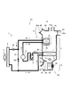
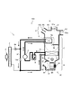
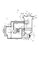
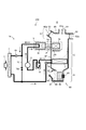
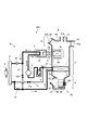
- FIG. 1 is a schematic view of a vehicle air conditioner to which a refrigeration cycle apparatus according to a first embodiment of the present invention is applied. It is a schematic diagram explaining the case where the interior of a vehicle is cooled by the air-conditioner for vehicles to which the refrigerating cycle device concerning a first embodiment is applied. It is the schematic which illustrates the case where the vehicle interior of a vehicle is heated by the vehicle air conditioner which applied the refrigerating-cycle apparatus which concerns on 1st embodiment. It is the schematic which demonstrates the case where dehumidification heating of the vehicle interior is carried out by the vehicle air conditioner which applied the refrigerating-cycle apparatus which concerns on 1st embodiment.
- FIG. 1 shows a vehicle air conditioner 100 according to a first embodiment of the present invention.
- the vehicle air conditioner 100 of the present embodiment is mounted on a vehicle (not shown) having a battery for storing the electric power of a vehicle travel motor, and blows out the refrigerating cycle device 1 and the blown air A into the vehicle interior R of the vehicle. And an air conditioning unit 80.
- the refrigeration cycle apparatus 1 includes a compressor 2 that compresses and discharges the sucked refrigerant, a heat radiating portion 3 capable of radiating the heat of the refrigerant discharged from the compressor 2 to the blast air A, and the refrigerant flowing out of the heat radiating portion 3
- An outdoor heat exchanger 4 capable of exchanging heat with the outside air F of the vehicle, and an evaporator capable of evaporating the refrigerant flowing out of the outdoor heat exchanger 4 and absorbing heat from the blown air A upstream of the heat radiating portion 3 5 and the accumulator 6 which stores the refrigerant flowing out of the evaporator 5 and flows out the vapor phase refrigerant
- the first throttle valve 4 a capable of depressurizing the refrigerant flowing into the outdoor heat exchanger 4 and the evaporator 5
- a second throttle valve 5a capable of reducing the pressure of the refrigerant, and the refrigerant flowing out of the heat radiation portion 3 can flow through the first throttle valve 4a and the
- the refrigeration cycle apparatus 1 is appropriately connected by a pipe, and the refrigerant is enclosed inside.
- the black point shown by piping of FIG. 1 is a junction or junction of a refrigerant
- the air conditioning unit 80 is disposed in the room R of the vehicle, and includes a blowing unit B, a temperature adjusting unit C, and a blowing unit D.
- the blower unit B, the temperature adjustment unit C, and the blowout unit D are configured as separate devices. Alternatively, they are integrally configured.
- the blower unit B has a blower case 81 in which an air flows inside and an inside air introduction port 82 opened to the room R of the vehicle and an outside air introduction port 83 capable of introducing outside air F are formed, an inside air introduction port 82 and an outside air introduction port
- An inside / outside air switching door 84 which opens and closes 83, a motor 85, and a fan 86 which is fixed to the rotation shaft of the motor 85 and accommodated in a blower case 81 are provided.
- the fan 86 is preferably a sirocco fan.
- the temperature adjustment unit C is disposed upstream of the evaporator 5 and the heat radiating unit 3 and the heat radiating unit 3 which are a part of the refrigeration cycle apparatus 1 and the housing 87 through which the blowing air A flows.
- the mix door 88 As shown in FIG. 1, the heat radiating portion 3 is arranged to occupy a part in the cross sectional direction of the housing 87, and the blown air A having flowed out of the evaporator 5 dissipates heat and a region through which the heat radiating portion 3 flows. It is possible to flow through the area bypassing the part 3.
- the mix door 88 By appropriately changing the position of the mix door 88, the ratio of the air flowing through the radiator 5 to the air flowing around the radiator 3 and the air bypassing the radiator 3 can be adjusted.
- the blowout unit D includes a housing 89 through which the blown air A flows, blowout ports 90, 91, 92 formed in the housing 89, and air distribution doors 90a, 91a, 92a for adjusting the opening degree of the blowout port.
- the air heated by the evaporator 5, the mix door 88, and the heat radiating portion 3 can be blown out from the desired air outlet to the vehicle interior R.
- the compressor 2 is driven to suck the gas phase refrigerant flowing out of the accumulator 6, compress it to a high temperature and high pressure, and discharge it.
- the compressor 2 can be driven by electric power.
- the heat radiating portion 3 is an indoor refrigerant radiator 3a into which the refrigerant discharged from the compressor 2 can flow and exchange heat with part or all of the blown air A. It comprises a plurality of tubes made of aluminum alloy or metal, through which the refrigerant passes, and a plurality of fins disposed between the tubes and radiating heat of the refrigerant to the blast air A.
- the outdoor heat exchanger 4 is a heat exchanger in which the refrigerant flowing out of the heat radiating portion 3 can flow in and exchange heat with the outside air F. It comprises a plurality of tubes made of aluminum alloy or metal, through which the refrigerant passes, and a plurality of fins disposed between the tubes. By decompressing the refrigerant flowing into the outdoor heat exchanger 4 with the first throttle valve 4a, the refrigerant can be evaporated inside the outdoor heat exchanger, and heat can be absorbed from the outside air F into the refrigerant. That is, it can be used as a heat sink.
- a relatively high-temperature high-pressure refrigerant can be made to flow into the outdoor heat exchanger 4, and the heat of the refrigerant can be released to the outside air F it can. That is, it can be used as a radiator.
- the evaporator 5 is a cooling heat exchanger capable of receiving the refrigerant flowing out of the outdoor heat exchanger 4 and exchanging heat with the blown air A. It comprises a plurality of tubes made of aluminum alloy or metal through which the refrigerant passes, and a plurality of fins disposed between the tubes for cooling the blast air A.
- the refrigerant flowing out of the evaporator 5 flows in, the gas phase and the liquid phase are separated inside, and the gas phase refrigerant flows out.
- the operation of the refrigeration cycle apparatus 1 is stabilized.
- lubricating oil mixed, precipitated or separated in the liquid phase refrigerant can be included in the flowing out gas phase refrigerant according to a method and configuration known in the prior art.
- the first throttle valve 4a is an electronic expansion valve capable of adjusting the opening degree of the valve. This can be done by throttling the refrigerant flow path. Furthermore, it is preferable that the refrigerant channel can be closed.
- the second throttle valve 5a is an electronic expansion valve capable of adjusting the opening degree of the valve.
- it is a conventional expansion valve that adjusts the opening degree of the valve by sensing the temperature or pressure of the refrigerant flowing out of the evaporator 5. This can be done by throttling the refrigerant flow path.
- FIG. 2 is a schematic view illustrating a case where the vehicle air conditioner 100 according to the first embodiment of the present invention is operated to cool the interior R of the vehicle.
- the portion through which the refrigerant flows in the refrigerant flow path is shown using a thick line. Further, the direction in which the refrigerant flows is indicated by an arrow.
- the motor 85 is driven to rotate the fan 86, and the outside air introduction port 83 is opened by the inside / outside air switching door 84 to introduce outside air into the blower case 81.
- the outside air introduced into the blower case 81 is blown toward the temperature control unit C as the blown air A.
- the compressor 2 is driven to discharge a high temperature and high pressure refrigerant.
- the discharged refrigerant flows into the heat radiating portion 3 (indoor refrigerant radiator 3a).
- the mix door 88 is positioned so as to close the upstream surface of the heat radiating portion 3 and guides all the blowing air A having flowed out of the evaporator 5 to the area around the heat radiating portion 3. For this reason, heat exchange is not performed between the heat radiating portion 3 (indoor refrigerant radiator 3a) and the blown air A, and the blown air A is not heated.
- the refrigerant that has flowed out of the heat radiating portion 3 passes through the first throttle valve 4a in the high temperature / high pressure state and flows into the outdoor heat exchanger 4.
- the first throttle valve 4a does not depressurize the refrigerant.
- the first on-off valve 10a is closed.
- the high-temperature and high-pressure refrigerant flows into the outdoor heat exchanger 4 as it is at high temperature and high pressure, is cooled by heat exchange with the outside air F, and energy (enthalpy) is reduced.
- the refrigerant having flowed out of the outdoor heat exchanger 4 passes through the second throttle valve and flows into the evaporator 5.
- the second throttle valve 5a depressurizes the refrigerant.
- the refrigerant whose energy has been reduced is decompressed and expanded, flows into the evaporator 5, and exchanges heat with the blown air A.
- the refrigerant that has evaporated inside the evaporator 5 absorbs heat from the blown air A, and the blown air A is cooled.
- the refrigerant that has flowed out of the evaporator 5 flows into the accumulator 6 and is separated into a gas phase refrigerant and a liquid phase refrigerant. Then, the gas phase refrigerant flows out of the accumulator 6 and is again drawn into the compressor 2.
- the blown air A cooled by the evaporator 5 is supplied to the vehicle interior R of the vehicle without passing through the blowout port without being heated by the heat radiating portion 3 (indoor refrigerant radiator 3a).
- FIG. 2 it is shown passing through the air outlet 91 corresponding to the vent air outlet and being supplied to the vehicle interior R of the vehicle.
- FIG. 3 is a schematic view illustrating a case where the vehicle air conditioner 100 according to the first embodiment of the present invention is operated to heat the interior R of the vehicle.
- the portion through which the refrigerant flows in the refrigerant flow path is shown using a thick line. Further, the direction in which the refrigerant flows is indicated by an arrow.
- the motor 85 is driven to rotate the fan 86, and the inside air introduction port 82 is opened by the inside / outside air switching door 84 to introduce inside air into the blower case 81.
- the inside air introduced into the blower case 81 is blown toward the temperature control unit C as the blown air A.
- the compressor 2 is driven to discharge a high temperature and high pressure refrigerant.
- the discharged refrigerant flows into the heat radiating portion 3 (indoor refrigerant radiator 3a).
- the mix door 88 is positioned so as to open the upstream surface of the heat radiating portion 3 and guides all the blowing air A having flowed out of the evaporator 5 to the area through which the heat radiating portion 3 flows. Therefore, heat exchange is performed between the heat radiating portion 3 (indoor refrigerant radiator 3a) and the blowing air A, and the blowing air A is heated.
- the refrigerant flowing out of the heat radiating portion 3 passes through the first throttle valve 4a and flows into the outdoor heat exchanger 4 in a state where the temperature is high although the pressure is high.
- the first throttle valve 4a reduces the pressure of the refrigerant.
- the first on-off valve 10a is closed. Accordingly, the refrigerant is decompressed and expanded, flows into the outdoor heat exchanger 4, and exchanges heat with the outside air F. Then, the refrigerant evaporated inside the outdoor heat exchanger 4 absorbs heat from the outside air F.
- the refrigerant having flowed out of the outdoor heat exchanger 4 passes through the second throttle valve and flows into the evaporator 5.
- the second throttle valve 5a does not depressurize the refrigerant.
- the refrigerant flowing into the evaporator 5 has been subjected to heat exchange with the outside air F in the outdoor heat exchanger 4, but its energy is still small, and the refrigerant flowing into the evaporator 5 exchanges heat with the blast air A. Then, the refrigerant flowing through the evaporator 5 absorbs heat from the blast air A, and the blast air A is cooled.
- the refrigerant that has flowed out of the evaporator 5 flows into the accumulator 6 and is separated into a gas phase refrigerant and a liquid phase refrigerant. Then, the gas phase refrigerant flows out of the accumulator 6 and is again drawn into the compressor 2.
- the blast air A cooled by the evaporator 5 is heated by the heat radiating portion 3 (indoor refrigerant radiator 3a), passes through any of the blowout ports, and is supplied to the vehicle interior R of the vehicle.
- the heat radiating portion 3 indoor refrigerant radiator 3a
- FIG. 3 it is shown passing through the air outlet 90 corresponding to the foot air outlet and being supplied to the vehicle interior R of the vehicle.
- the amount of heat Q3 that the radiator 3 (indoor refrigerant radiator 3a) heats the blown air A is the amount of heat Q4 absorbed by the outdoor heat exchanger 4 from the outside air F, and the amount of heat Q5 absorbed by the evaporator from the blown air A. It is a total. Even if the blast air A is cooled by the evaporator 5, the blast air A is heated as a result because a larger amount of heat Q4 is given.
- FIG. 4 is a schematic view illustrating a case where the vehicle air conditioner 100 according to the first embodiment of the present invention is operated to dehumidify the interior R of the vehicle.
- the portion through which the refrigerant flows in the refrigerant flow path is shown using a thick line. Further, the direction in which the refrigerant flows is indicated by an arrow.
- the motor 85 is driven to rotate the fan 86, and the outside air introduction port 83 is opened by the inside / outside air switching door 84 to introduce outside air into the blower case 81.
- the outside air introduced into the blower case 81 is blown toward the temperature control unit C as the blown air A.
- the compressor 2 is driven to discharge a high temperature and high pressure refrigerant.
- the discharged refrigerant flows into the heat radiating portion 3 (indoor refrigerant radiator 3a).
- the mix door 88 is positioned so as to open the upstream surface of the heat radiating portion 3 and guides all the blowing air A having flowed out of the evaporator 5 to the area through which the heat radiating portion 3 flows. Therefore, heat exchange is performed between the heat radiating portion 3 (indoor refrigerant radiator 3a) and the blowing air A, and the blowing air A is heated.
- the refrigerant having flowed out of the heat radiating portion 3 flows through the first bypass channel 10. That is, it flows around the 1st throttle valve 4a and the outdoor heat exchanger 4 to the 2nd throttle valve 5a.
- the refrigerant flowing to the second throttle valve 5a reaches the second throttle valve 5a in a state where the temperature is high although the pressure is high.
- the refrigerant is depressurized by throttling the second throttle valve 5a.
- the refrigerant is decompressed and expanded, flows into the evaporator 5, evaporates, and absorbs heat from the blown air A.
- the refrigerant that has flowed out of the evaporator 5 flows into the accumulator 6 and is separated into a gas phase refrigerant and a liquid phase refrigerant. Then, the gas phase refrigerant flows out of the accumulator 6 and is again drawn into the compressor 2.
- the blast air A cooled by the evaporator 5 is heated by the heat radiating portion 3 (indoor refrigerant radiator 3a), passes through any of the blowout ports, and is supplied to the vehicle interior R of the vehicle.
- the heat radiating portion 3 indoor refrigerant radiator 3a
- FIG. 3 it is shown passing through the air outlet 90 corresponding to the foot air outlet and the air outlet 91 corresponding to the vent air outlet to be supplied to the vehicle interior R of the vehicle.
- the heat quantity Q3 by which the heat radiating portion 3 (indoor refrigerant radiator 3a) heats the blown air A is substantially the same as the heat quantity Q5 absorbed by the evaporator from the blown air A. Even if the blown air A is cooled by the evaporator 5, substantially the same amount of heat Q5 is given. As a result, there is no or little temperature change of the blown air A, and it is dehumidified when it is cooled by the evaporator 5, It is supplied to the vehicle interior R of the vehicle.
- the lubricating oil recovery operation is performed. Specifically, when the controller recognizes that the charging of the battery has been started by the external power supply, as shown in FIG. 5, the first on-off valve 10a is closed, and then the compressor 2 is operated. Then, the refrigerant is circulated to the refrigeration cycle apparatus 1. When the battery is being charged, the vehicle is at a standstill, and the necessity to air-condition the interior of the vehicle is reduced compared to when the vehicle is traveling. It is suitable to do.
- each heat exchange (heating heat exchanger 3, outdoor heat exchanger 4, and evaporator 5) which the refrigeration cycle system 1 has is for the purpose different from that at the time of air conditioning operation of the vehicle interior It is used. For this reason, it is desirable that the lubricating oil recovery operation be performed in a state where the driving of the motor 85 is stopped and the blowing air A does not flow.
- the recovery operation of the lubricating oil is preferably completed in a time shorter than the charging time of the battery. Specifically, it is preferably performed for 50 seconds to 120 seconds. If the operating time is shorter than this, the lubricating oil may not be recovered sufficiently. Also, even if the operation time is made longer than this, there is substantially no change in the amount of recovered lubricating oil.
- the collecting operation of the lubricating oil is also stopped, since the vehicle may travel. It is possible to carry out the air conditioning operation of the interior of the vehicle prior to the recovery operation of the lubricating oil.
- FIG. 6 shows a heating operation mode in the vehicle air conditioner 200 according to the second embodiment of the present invention.
- the configuration of the heat dissipation unit 3 is different from that of the first embodiment. Therefore, the heat dissipating unit 3 will be mainly described, and the description of the other parts to which the same reference numerals as in the first embodiment are given will be omitted.
- the heat dissipation unit 3 is a water condenser 3b into which the refrigerant discharged from the compressor 2 flows, a hot water heat exchanger 3c for radiating heat of liquid heat medium such as water to the blast air A, and hot water heat exchange It has the warm water flow path 3w connected with the vessel 3c, and the water feeder P for circulating the warm water of the warm water flow path 3w.
- the water condenser 3b is also a part of the hot water flow path 3w, and is a heat exchanger that can exchange heat between the refrigerant and the water of the hot water flow path 3w.
- the motor 85 is driven to rotate the fan 86, and the inside air introduction port 82 is opened by the inside / outside air switching door 84 to introduce inside air into the blower case 81.
- the inside air introduced into the blower case 81 is blown toward the temperature control unit C as the blown air A.
- the compressor 2 is driven to discharge a high-temperature and high-pressure refrigerant.
- the discharged refrigerant flows into the water condenser 3b which is a part of the heat radiating portion 3 and radiates heat to the hot water flow path 3w.
- the hot water of the hot water flow path 3w is circulated by the water feeding device P, and the hot water flows into the hot water type heat exchanger 3c.
- the mix door 88 is positioned to open the upstream surface of the hot water type heat exchanger 3c, and guides all the blowing air A having flowed out of the evaporator 5 to the area through which the hot water type heat exchanger 3c flows. . For this reason, heat exchange is performed with the warm water type heat exchanger 3c and the blowing air A, and the blowing air A is heated.
- the refrigerant having flowed out of the water condenser 3b is the first throttle valve 4a, the outdoor heat exchanger 4, the second throttle valve 5a, the evaporator 5, the accumulator in the same manner as the heating operation mode of the first embodiment shown in FIG. It flows in order of 6 and is again drawn into the compressor 2.
- the air conditioning system for vehicles 200 is stopped when the air temperature is low, the hot water in the water condenser 3b, the hot water heat exchanger 3c, the water feeding device P, and the hot water flow path 3w radiates heat and cold water It becomes. Then, when the air temperature rises due to solar radiation or the like, the temperature rise of the cold water becomes moderate because the heat capacity is large relative to the rate of temperature rise of the refrigeration cycle 1a. For this reason, the viscosity of the lubricating oil present in the vicinity of the water condenser 3b may increase and may be stagnant.
- the lubricating oil recovery operation is performed. Specifically, when it is recognized by the control device that charging of the battery has been started by the external power supply, the first on-off valve 10a is closed and the water feeding device P is stopped, as shown in FIG. Next, the compressor 2 is operated to circulate the refrigerant through the refrigeration cycle apparatus 1a.
- the battery is being charged, the vehicle is at a standstill, and the necessity to air-condition the interior of the vehicle is reduced compared to when the vehicle is traveling. It is suitable to do.
- each heat exchange hot water type heat exchanger 3, outdoor heat exchanger 4, and evaporator 5 which the refrigeration cycle apparatus 1a has is for the purpose different from that at the time of air conditioning operation of the vehicle interior It is used. For this reason, it is desirable that the lubricating oil recovery operation be performed in a state where the driving of the motor 85 is stopped and the blowing air A does not flow.
- the lubricating oil is expected to stay in the water condenser 3 b and / or the outdoor heat exchanger 4, so it is desirable to supply a high temperature and high pressure refrigerant to the water condenser 3 b and the outdoor heat exchanger 4. For this reason, the first throttle valve 4a is not throttled. On the other hand, it is desirable to throttle the second throttle valve 5a. Since the refrigerant in the refrigerant flow path from the compressor 2 to the second throttle valve 5a can be brought into a high temperature and high pressure state, the lubricating oil accumulated in the water condenser 3b and / or the outdoor heat exchanger 4 can be efficiently recovered.
- FIG. 8 shows a heating operation mode in the vehicle air conditioner 300 according to the third embodiment of the present invention.
- the configuration of the refrigeration cycle 1b is different from that of the second embodiment. More specifically, the refrigerant flowing out of the outdoor heat exchanger 4 is provided with a second bypass flow passage 11 which can pass the second throttle valve 5 a and the evaporator 5 to the accumulator 6.
- the second bypass channel 11 includes a second on-off valve 11 a that can close the second bypass channel.
- a check valve 12 is provided between the outdoor heat exchanger 4 and the second bypass passage 11 to prevent backflow of the refrigerant. Therefore, the refrigeration cycle 1b will be mainly described, and the description of the other parts to which the same reference numerals as in the second embodiment are given will be omitted.
- the refrigeration cycle 1b includes the second bypass flow passage 11 that allows the refrigerant that has flowed out of the outdoor heat exchanger 4 to flow to the accumulator 6 by bypassing the second throttle valve 5a and the evaporator 5. .
- the first on-off valve 10a is closed and the second on-off valve 11a is opened, and then the compressor 2 is operated, the high temperature and high pressure refrigerant discharged from the compressor 1 is the water condenser 3b, the first throttle valve 4a, and the outdoor heat exchange , The first on-off valve 11a, and the accumulator 6 in this order, and the compressor 2 is again sucked.
- the refrigerant releases heat (radiates heat) to the hot water flow path 3w with the water condenser 3, and absorbs heat from the outside air F with the outdoor heat exchanger 4 ( Heat absorption).
- the motor 85 is operated to flow the blast air A and the mix door 88 is set to a position where the upstream surface of the hot water heat exchanger 3c is opened, so that the blast air A is made hot air without being dehumidified by the evaporator 5. be able to.
- the hot water in the water condenser 3b, the hot water heat exchanger 3c, the water feeding device P, and the hot water flow path 3w dissipates heat and becomes cold water. Then, when the air temperature rises due to solar radiation or the like, the temperature rise of the cold water becomes moderate because the heat capacity is large relative to the rate of temperature rise of the refrigeration cycle 1a. For this reason, the viscosity of the lubricating oil present in the vicinity of the water condenser 3b may increase and may be stagnant.
- the lubricating oil recovery operation is performed. Specifically, when the controller recognizes that the charging of the battery is started by the external power supply, as shown in FIG. 9, the first on-off valve 10a and the second on-off valve 11a are closed and the water is supplied. The apparatus P is stopped, and then the compressor 2 is operated to circulate the refrigerant to the refrigeration cycle apparatus 1b. At the time of recovery operation of lubricating oil, each heat exchange (hot water type heat exchanger 3, outdoor heat exchanger 4, and evaporator 5) which the refrigeration cycle system 1b has is for the purpose different from that at the time of air conditioning operation of the vehicle interior It is used. For this reason, it is desirable that the lubricating oil recovery operation be performed in a state where the driving of the motor 85 is stopped and the blowing air A does not flow.
- each heat exchange hot water type heat exchanger 3, outdoor heat exchanger 4, and evaporator 5
- the lubricating oil is expected to stay in the water condenser 3b and / or the outdoor heat exchanger 4, so it is desirable to supply a high-temperature high-pressure refrigerant to the water condenser 3b. For this reason, it is desirable to throttle the second throttle valve 5a. Since the refrigerant in the refrigerant flow path from the compressor 2 to the second throttle valve 5a can be brought into a high temperature and high pressure state, the lubricating oil accumulated in the water condenser 3b and / or the outdoor heat exchanger 4 can be efficiently recovered.
- a third bypass flow passage (not shown) that allows the refrigerant discharged from the compressor 2 to flow to the first throttle valve 4 a by bypassing the indoor refrigerant radiator 3 a
- the battery is charged by the external power supply
- the compressor 2 is then operated.
- the refrigerant discharged from the compressor 2 can flow through the indoor refrigerant radiator 3a and the outdoor heat exchanger 4 to reliably collect the retained lubricating oil.
- the blower according to the present invention can be manufactured industrially, and can be suitably used particularly for a vehicle air conditioner.
Landscapes
- Engineering & Computer Science (AREA)
- Physics & Mathematics (AREA)
- Thermal Sciences (AREA)
- Mechanical Engineering (AREA)
- General Engineering & Computer Science (AREA)
- Air-Conditioning For Vehicles (AREA)
Abstract
Le problème décrit par la présente invention consiste, dans un dispositif à cycle de réfrigération d'un dispositif de climatisation d'automobile qui comprend un passage de dérivation pour contourner un échangeur de chaleur, et qui est pourvu d'une fonction de refroidissement d'espace et d'une fonction de chauffage d'espace, à récupérer de manière fiable l'huile lubrifiante retenue à l'intérieur de l'échangeur de chaleur. La solution selon l'invention porte sur un dispositif à cycle de réfrigération 1 applicable à un dispositif de climatisation d'automobile, qui est pourvu : d'un compresseur 2 ; d'une partie de dissipation de chaleur 3 à travers laquelle s'écoule un fluide frigorigène rejeté depuis le compresseur ; d'un échangeur de chaleur extérieur 4 à travers lequel s'écoule le fluide frigorigène qui s'est écoulé hors de la partie de dissipation de chaleur ; d'un évaporateur 5 à travers lequel s'écoule le fluide frigorigène qui s'est écoulé hors de l'échangeur de chaleur extérieur ; d'un accumulateur 6 dans lequel est stocké le fluide frigorigène qui s'est écoulé hors de l'évaporateur ; d'un premier passage d'écoulement de dérivation 10 contournant l'échangeur de chaleur extérieur ; et d'une première soupape ouverte/fermée pouvant être fermée 10a disposée dans le premier passage d'écoulement de dérivation ; la première soupape ouverte/fermée 10a étant fermée et le compresseur 2 fonctionnant lorsqu'une batterie est en cours de charge au moyen d'une alimentation électrique externe.
Applications Claiming Priority (2)
| Application Number | Priority Date | Filing Date | Title |
|---|---|---|---|
| JP2017177433A JP2019051832A (ja) | 2017-09-15 | 2017-09-15 | 冷凍サイクル装置 |
| JP2017-177433 | 2017-09-15 |
Publications (1)
| Publication Number | Publication Date |
|---|---|
| WO2019054401A1 true WO2019054401A1 (fr) | 2019-03-21 |
Family
ID=65722826
Family Applications (1)
| Application Number | Title | Priority Date | Filing Date |
|---|---|---|---|
| PCT/JP2018/033765 Ceased WO2019054401A1 (fr) | 2017-09-15 | 2018-09-12 | Dispositif à cycle de réfrigération |
Country Status (2)
| Country | Link |
|---|---|
| JP (1) | JP2019051832A (fr) |
| WO (1) | WO2019054401A1 (fr) |
Cited By (3)
| Publication number | Priority date | Publication date | Assignee | Title |
|---|---|---|---|---|
| CN110065362A (zh) * | 2018-01-23 | 2019-07-30 | 福特全球技术公司 | 电气化车辆制冷剂系统 |
| CN115315601A (zh) * | 2020-03-23 | 2022-11-08 | 株式会社电装 | 制冷循环装置 |
| CN116745151A (zh) * | 2020-12-02 | 2023-09-12 | 法雷奥热系统公司 | 包括储液器旁通支路的制冷剂流体回路 |
Families Citing this family (2)
| Publication number | Priority date | Publication date | Assignee | Title |
|---|---|---|---|---|
| JP7331214B1 (ja) | 2022-07-27 | 2023-08-22 | 三菱重工サーマルシステムズ株式会社 | 空調装置および空調装置の制御方法 |
| JP7279246B1 (ja) * | 2022-08-31 | 2023-05-22 | 三菱重工サーマルシステムズ株式会社 | 空調装置 |
Citations (4)
| Publication number | Priority date | Publication date | Assignee | Title |
|---|---|---|---|---|
| WO2014136450A1 (fr) * | 2013-03-06 | 2014-09-12 | パナソニック株式会社 | Dispositif de climatisation de véhicule |
| JP2015048041A (ja) * | 2013-09-04 | 2015-03-16 | サンデン株式会社 | 車両用空気調和装置 |
| JP2015183872A (ja) * | 2014-03-20 | 2015-10-22 | 株式会社デンソー | 蒸気圧縮式冷凍サイクル装置 |
| WO2016043309A1 (fr) * | 2014-09-19 | 2016-03-24 | サンデンホールディングス株式会社 | Dispositif climatiseur de véhicule |
-
2017
- 2017-09-15 JP JP2017177433A patent/JP2019051832A/ja active Pending
-
2018
- 2018-09-12 WO PCT/JP2018/033765 patent/WO2019054401A1/fr not_active Ceased
Patent Citations (4)
| Publication number | Priority date | Publication date | Assignee | Title |
|---|---|---|---|---|
| WO2014136450A1 (fr) * | 2013-03-06 | 2014-09-12 | パナソニック株式会社 | Dispositif de climatisation de véhicule |
| JP2015048041A (ja) * | 2013-09-04 | 2015-03-16 | サンデン株式会社 | 車両用空気調和装置 |
| JP2015183872A (ja) * | 2014-03-20 | 2015-10-22 | 株式会社デンソー | 蒸気圧縮式冷凍サイクル装置 |
| WO2016043309A1 (fr) * | 2014-09-19 | 2016-03-24 | サンデンホールディングス株式会社 | Dispositif climatiseur de véhicule |
Cited By (4)
| Publication number | Priority date | Publication date | Assignee | Title |
|---|---|---|---|---|
| CN110065362A (zh) * | 2018-01-23 | 2019-07-30 | 福特全球技术公司 | 电气化车辆制冷剂系统 |
| CN115315601A (zh) * | 2020-03-23 | 2022-11-08 | 株式会社电装 | 制冷循环装置 |
| CN115315601B (zh) * | 2020-03-23 | 2024-02-23 | 株式会社电装 | 制冷循环装置 |
| CN116745151A (zh) * | 2020-12-02 | 2023-09-12 | 法雷奥热系统公司 | 包括储液器旁通支路的制冷剂流体回路 |
Also Published As
| Publication number | Publication date |
|---|---|
| JP2019051832A (ja) | 2019-04-04 |
Similar Documents
| Publication | Publication Date | Title |
|---|---|---|
| JP6838527B2 (ja) | 車両用空調装置 | |
| JP6791052B2 (ja) | 空調装置 | |
| JP6481668B2 (ja) | 冷凍サイクル装置 | |
| JP6838535B2 (ja) | 冷凍サイクル装置 | |
| JP6485390B2 (ja) | 冷凍サイクル装置 | |
| CN109501552B (zh) | 用于车辆的热泵系统 | |
| CN107636401B (zh) | 制冷循环装置 | |
| JP6838518B2 (ja) | 冷凍サイクル装置 | |
| CN113227673B (zh) | 温度调整装置 | |
| CN111448432A (zh) | 热泵系统 | |
| JP2018035951A (ja) | 冷凍サイクル装置 | |
| JP2019034587A (ja) | 空調装置 | |
| JP2019051832A (ja) | 冷凍サイクル装置 | |
| JP6060799B2 (ja) | 車両用空調装置 | |
| KR20210107361A (ko) | 차량용 냉난방 시스템 | |
| JP4055739B2 (ja) | 車両用空調装置 | |
| JP3272663B2 (ja) | 車両用空調装置 | |
| JP7392296B2 (ja) | 冷凍サイクル装置 | |
| WO2020246306A1 (fr) | Dispositif de climatisation de véhicule | |
| US20230019811A1 (en) | Coolant circuit of a vehicle adapted to fast charging of a storage device | |
| CN115397683A (zh) | 车辆空调系统 | |
| CN115427242A (zh) | 车辆空调系统 | |
| JP6341118B2 (ja) | 冷凍サイクル装置 | |
| WO2020241612A1 (fr) | Dispositif de climatisation de véhicule | |
| JP7521481B2 (ja) | 車両用空調装置 |
Legal Events
| Date | Code | Title | Description |
|---|---|---|---|
| 121 | Ep: the epo has been informed by wipo that ep was designated in this application |
Ref document number: 18856415 Country of ref document: EP Kind code of ref document: A1 |
|
| NENP | Non-entry into the national phase |
Ref country code: DE |
|
| 122 | Ep: pct application non-entry in european phase |
Ref document number: 18856415 Country of ref document: EP Kind code of ref document: A1 |