WO2019054666A1 - Procédé de fabrication d'une cellule de batterie de type poche, comprenant un calibrage de gabarit - Google Patents
Procédé de fabrication d'une cellule de batterie de type poche, comprenant un calibrage de gabarit Download PDFInfo
- Publication number
- WO2019054666A1 WO2019054666A1 PCT/KR2018/009852 KR2018009852W WO2019054666A1 WO 2019054666 A1 WO2019054666 A1 WO 2019054666A1 KR 2018009852 W KR2018009852 W KR 2018009852W WO 2019054666 A1 WO2019054666 A1 WO 2019054666A1
- Authority
- WO
- WIPO (PCT)
- Prior art keywords
- battery cell
- pouch
- jig
- shaped battery
- electrolyte
- Prior art date
- Legal status (The legal status is an assumption and is not a legal conclusion. Google has not performed a legal analysis and makes no representation as to the accuracy of the status listed.)
- Ceased
Links
Images

Classifications
-
- H—ELECTRICITY
- H01—ELECTRIC ELEMENTS
- H01M—PROCESSES OR MEANS, e.g. BATTERIES, FOR THE DIRECT CONVERSION OF CHEMICAL ENERGY INTO ELECTRICAL ENERGY
- H01M4/00—Electrodes
- H01M4/02—Electrodes composed of, or comprising, active material
- H01M4/36—Selection of substances as active materials, active masses, active liquids
- H01M4/48—Selection of substances as active materials, active masses, active liquids of inorganic oxides or hydroxides
- H01M4/485—Selection of substances as active materials, active masses, active liquids of inorganic oxides or hydroxides of mixed oxides or hydroxides for inserting or intercalating light metals, e.g. LiTi2O4 or LiTi2OxFy
-
- H—ELECTRICITY
- H01—ELECTRIC ELEMENTS
- H01M—PROCESSES OR MEANS, e.g. BATTERIES, FOR THE DIRECT CONVERSION OF CHEMICAL ENERGY INTO ELECTRICAL ENERGY
- H01M4/00—Electrodes
- H01M4/02—Electrodes composed of, or comprising, active material
- H01M4/04—Processes of manufacture in general
- H01M4/0438—Processes of manufacture in general by electrochemical processing
- H01M4/044—Activating, forming or electrochemical attack of the supporting material
- H01M4/0445—Forming after manufacture of the electrode, e.g. first charge, cycling
- H01M4/0447—Forming after manufacture of the electrode, e.g. first charge, cycling of complete cells or cells stacks
-
- H—ELECTRICITY
- H01—ELECTRIC ELEMENTS
- H01M—PROCESSES OR MEANS, e.g. BATTERIES, FOR THE DIRECT CONVERSION OF CHEMICAL ENERGY INTO ELECTRICAL ENERGY
- H01M10/00—Secondary cells; Manufacture thereof
- H01M10/04—Construction or manufacture in general
- H01M10/0404—Machines for assembling batteries
-
- H—ELECTRICITY
- H01—ELECTRIC ELEMENTS
- H01M—PROCESSES OR MEANS, e.g. BATTERIES, FOR THE DIRECT CONVERSION OF CHEMICAL ENERGY INTO ELECTRICAL ENERGY
- H01M10/00—Secondary cells; Manufacture thereof
- H01M10/04—Construction or manufacture in general
- H01M10/049—Processes for forming or storing electrodes in the battery container
-
- H—ELECTRICITY
- H01—ELECTRIC ELEMENTS
- H01M—PROCESSES OR MEANS, e.g. BATTERIES, FOR THE DIRECT CONVERSION OF CHEMICAL ENERGY INTO ELECTRICAL ENERGY
- H01M10/00—Secondary cells; Manufacture thereof
- H01M10/05—Accumulators with non-aqueous electrolyte
- H01M10/052—Li-accumulators
- H01M10/0525—Rocking-chair batteries, i.e. batteries with lithium insertion or intercalation in both electrodes; Lithium-ion batteries
-
- H—ELECTRICITY
- H01—ELECTRIC ELEMENTS
- H01M—PROCESSES OR MEANS, e.g. BATTERIES, FOR THE DIRECT CONVERSION OF CHEMICAL ENERGY INTO ELECTRICAL ENERGY
- H01M10/00—Secondary cells; Manufacture thereof
- H01M10/42—Methods or arrangements for servicing or maintenance of secondary cells or secondary half-cells
- H01M10/44—Methods for charging or discharging
- H01M10/446—Initial charging measures
-
- H—ELECTRICITY
- H01—ELECTRIC ELEMENTS
- H01M—PROCESSES OR MEANS, e.g. BATTERIES, FOR THE DIRECT CONVERSION OF CHEMICAL ENERGY INTO ELECTRICAL ENERGY
- H01M4/00—Electrodes
- H01M4/02—Electrodes composed of, or comprising, active material
- H01M4/04—Processes of manufacture in general
- H01M4/043—Processes of manufacture in general involving compressing or compaction
-
- H—ELECTRICITY
- H01—ELECTRIC ELEMENTS
- H01M—PROCESSES OR MEANS, e.g. BATTERIES, FOR THE DIRECT CONVERSION OF CHEMICAL ENERGY INTO ELECTRICAL ENERGY
- H01M4/00—Electrodes
- H01M4/02—Electrodes composed of, or comprising, active material
- H01M4/36—Selection of substances as active materials, active masses, active liquids
- H01M4/48—Selection of substances as active materials, active masses, active liquids of inorganic oxides or hydroxides
-
- H—ELECTRICITY
- H01—ELECTRIC ELEMENTS
- H01M—PROCESSES OR MEANS, e.g. BATTERIES, FOR THE DIRECT CONVERSION OF CHEMICAL ENERGY INTO ELECTRICAL ENERGY
- H01M4/00—Electrodes
- H01M4/02—Electrodes composed of, or comprising, active material
- H01M4/36—Selection of substances as active materials, active masses, active liquids
- H01M4/58—Selection of substances as active materials, active masses, active liquids of inorganic compounds other than oxides or hydroxides, e.g. sulfides, selenides, tellurides, halogenides or LiCoFy; of polyanionic structures, e.g. phosphates, silicates or borates
-
- H—ELECTRICITY
- H01—ELECTRIC ELEMENTS
- H01M—PROCESSES OR MEANS, e.g. BATTERIES, FOR THE DIRECT CONVERSION OF CHEMICAL ENERGY INTO ELECTRICAL ENERGY
- H01M50/00—Constructional details or processes of manufacture of the non-active parts of electrochemical cells other than fuel cells, e.g. hybrid cells
- H01M50/10—Primary casings; Jackets or wrappings
- H01M50/102—Primary casings; Jackets or wrappings characterised by their shape or physical structure
- H01M50/105—Pouches or flexible bags
-
- H—ELECTRICITY
- H01—ELECTRIC ELEMENTS
- H01M—PROCESSES OR MEANS, e.g. BATTERIES, FOR THE DIRECT CONVERSION OF CHEMICAL ENERGY INTO ELECTRICAL ENERGY
- H01M50/00—Constructional details or processes of manufacture of the non-active parts of electrochemical cells other than fuel cells, e.g. hybrid cells
- H01M50/60—Arrangements or processes for filling or topping-up with liquids; Arrangements or processes for draining liquids from casings
-
- H—ELECTRICITY
- H01—ELECTRIC ELEMENTS
- H01M—PROCESSES OR MEANS, e.g. BATTERIES, FOR THE DIRECT CONVERSION OF CHEMICAL ENERGY INTO ELECTRICAL ENERGY
- H01M50/00—Constructional details or processes of manufacture of the non-active parts of electrochemical cells other than fuel cells, e.g. hybrid cells
- H01M50/60—Arrangements or processes for filling or topping-up with liquids; Arrangements or processes for draining liquids from casings
- H01M50/609—Arrangements or processes for filling with liquid, e.g. electrolytes
-
- H—ELECTRICITY
- H01—ELECTRIC ELEMENTS
- H01M—PROCESSES OR MEANS, e.g. BATTERIES, FOR THE DIRECT CONVERSION OF CHEMICAL ENERGY INTO ELECTRICAL ENERGY
- H01M4/00—Electrodes
- H01M4/02—Electrodes composed of, or comprising, active material
- H01M4/36—Selection of substances as active materials, active masses, active liquids
- H01M4/38—Selection of substances as active materials, active masses, active liquids of elements or alloys
- H01M4/386—Silicon or alloys based on silicon
-
- Y—GENERAL TAGGING OF NEW TECHNOLOGICAL DEVELOPMENTS; GENERAL TAGGING OF CROSS-SECTIONAL TECHNOLOGIES SPANNING OVER SEVERAL SECTIONS OF THE IPC; TECHNICAL SUBJECTS COVERED BY FORMER USPC CROSS-REFERENCE ART COLLECTIONS [XRACs] AND DIGESTS
- Y02—TECHNOLOGIES OR APPLICATIONS FOR MITIGATION OR ADAPTATION AGAINST CLIMATE CHANGE
- Y02E—REDUCTION OF GREENHOUSE GAS [GHG] EMISSIONS, RELATED TO ENERGY GENERATION, TRANSMISSION OR DISTRIBUTION
- Y02E60/00—Enabling technologies; Technologies with a potential or indirect contribution to GHG emissions mitigation
- Y02E60/10—Energy storage using batteries
-
- Y—GENERAL TAGGING OF NEW TECHNOLOGICAL DEVELOPMENTS; GENERAL TAGGING OF CROSS-SECTIONAL TECHNOLOGIES SPANNING OVER SEVERAL SECTIONS OF THE IPC; TECHNICAL SUBJECTS COVERED BY FORMER USPC CROSS-REFERENCE ART COLLECTIONS [XRACs] AND DIGESTS
- Y02—TECHNOLOGIES OR APPLICATIONS FOR MITIGATION OR ADAPTATION AGAINST CLIMATE CHANGE
- Y02P—CLIMATE CHANGE MITIGATION TECHNOLOGIES IN THE PRODUCTION OR PROCESSING OF GOODS
- Y02P70/00—Climate change mitigation technologies in the production process for final industrial or consumer products
- Y02P70/50—Manufacturing or production processes characterised by the final manufactured product
Definitions
- the present invention relates to a method of manufacturing a pouch type battery cell including jig-grading, and more particularly, to a pouch type battery cell including a pouch type battery cell having a pouch type battery cell fixed to a jig, And a method for manufacturing a battery cell.
- the lithium secondary battery is classified into a cylindrical battery, a prismatic battery and a pouch-type battery according to the shape of the case.
- the cylindrical battery and the prismatic battery are batteries having a structure in which an electrode assembly is mounted on a can of a metal
- a pouch-shaped battery is a battery having a structure in which an electrode assembly is mounted on a pouch-shaped case of an aluminum laminate sheet.
- a pouch type battery which can be stacked with a high degree of integration, has a high energy density per unit weight, and is inexpensive and easy to deform has recently attracted much attention.
- the main task of the flexible pouch-type battery is to increase the volume capacity and safety at the same time.
- the lithium secondary battery which is an electrode assembly, can be exploded by high temperature and high pressure inside the battery due to an abnormal state of the battery, such as internal short circuit, overcharge, exposure to high temperature, drop or deformation due to external impact.
- Patent Document 1 discloses a method of manufacturing a secondary battery in which charging and discharging and shipping charge processes for setting a capacity rating of a battery are performed before a degassing process for removing gas generated in a battery cell, There is no specific technique for increasing the impregnation rate of the electrolyte solution.
- Patent Document 2 discloses a pressurizing clamp device used to prevent deformation of a battery cell during charging and discharging, but no method for reducing the amount of the discharged electrolyte in the process of degassing the battery cell has been disclosed.
- Patent Document 3 discloses a technique for minimizing a change in thickness of an electrode assembly that may occur during an activation process and thereby reducing the resistance inside the battery cell by pressing the outer surface of the battery case before charging and discharging for activation of the battery cell
- Patent Document 4 discloses a method for manufacturing a battery cell including a charging / discharging jig for charging / discharging the lithium polymer battery in a state in which an electrode of the lithium polymer battery is in close contact with a current passing piece by a pressing action of a voltage measuring piece, .
- Patent Documents 3 and 4 do not disclose a method for increasing the impregnation rate of an electrolyte solution in an electrode assembly.
- Patent Document 0001 Korean Patent Laid-Open Publication No. 2017-0033601
- Patent Document 0002 Japanese Laid-Open Patent Publication No. 2016-515291
- Patent Document 3 Korean Patent Laid-Open Publication No. 2016-0132572
- Patent Document 0004 Korean Registered Patent Study No. 0987942
- the present invention has been made to solve the above problems, and it is an object of the present invention to provide a pouch type battery cell in which a pouch type battery cell having been subjected to a primary charging step after an electrolyte is injected is placed in a pressing jig, When the grading step is performed, it is possible to prevent the shape of the battery cell from being deformed during the conversion process for charging / discharging the battery cell, and the impregnation rate of the electrolyte solution to the electrode assembly is increased. Therefore, It is an object of the present invention to provide a battery cell.
- the method of manufacturing a pouch-shaped battery cell according to the present invention includes a process of charging / discharging by applying pressure while a pouch-shaped battery cell into which an electrolyte is injected is fixed to a pressure jig.
- the pouch-shaped battery cell when the pouch-shaped battery cell is charged or discharged, the battery case is swollen or twisted due to expansion and gas generation of the electrode assembly.
- the pouch-shaped battery cell when the pouch-shaped battery cell is placed in the pressure jig, It is possible to prevent deformation of the shape of the battery cell, thereby preventing an increase in the defective ratio due to defective cell appearance.
- the amount of the remaining electrolyte decreases as the electrolyte is discharged together with the degassing process. This is a problem in terms of life characteristics.
- the pouch- The amount of the electrolytic solution injected in the degassing process can be reduced since the electrolytic solution is penetrated into the pores in the expanded electrode to increase the amount of electrolytic solution impregnated. Therefore, it is possible to solve the problem that the remaining amount of the electrolytic solution is insufficient and the cycle characteristics are deteriorated.
- the electrode assembly may be composed of a negative electrode including a silicon-based negative active material.
- the silicon-based negative active material may be one selected from the group consisting of SiC, SiO, SiM, And M may be any one selected from the group consisting of Ni, Co, B, Cr, Cu, Fe, Mn, Ti, Y and combinations thereof.
- carbon, lithium transition metal oxide or silicon compound can be used as the negative electrode active material of the secondary battery.
- the silicon compound When the silicon compound is used as the negative electrode active material, the silicon particle electrochemically absorbs and stores lithium atoms The reaction may take place and may involve a change in crystal morphology. As the reaction is absorbing and desorbing the above lithium atom progress of the silicon particle composition and crystal structure of Si (crystal structure: Fd3m), LiSi (crystal structure: I41 / a), Li 2 Si ( crystal structure: C2 / m ), Li 7 Si 2 (Pbam), and Li 22 Si 5 (F23). As the crystal structure is changed, the volume of the silicon particles is expanded about four times as compared with that before the lithium is inserted. As a result, the amount of the electrolyte impregnated increases as the pores between the expanded silicon particles increase.
- the silicon-based compound containing silicon is used as the negative electrode active material in this way, in the case where the impregnation amount of the electrolytic solution can be increased and the electrolytic solution can not be easily discharged to the outside, .
- the jig may have a structure capable of accommodating a plurality of pouch-shaped battery cells.
- the jig may include a plurality of pouch-shaped battery cells having a plurality of pouch- .
- the step (e) may further include a degassing step of discharging the gas of the jig-graded battery cell.
- the degassing step may include removing gas generated in the jig- And since the gas is not selectively absorbed but the electrolytic solution is also discharged at the same time, a high capacity battery in which an electrolyte is excessively required, must be made more difficult.
- the amount of the electrolytic solution discharged in the degassing process can be reduced because the degassing is performed after increasing the remaining amount of the electrolytic solution in the expanded negative electrode active material.
- the electrolyte solution can be injected by a general pouring method or a vacuum pouring method.
- a general pouring method a certain amount of electrolyte solution is poured into a pouch in a state where the battery cell is vertically set, and then the solution is poured in a vacuum atmosphere for about 3 minutes to 5 minutes wetting process.
- the vacuum liquor method is carried out in the following manner.
- a battery cell is mounted in a chamber of a princess liquor in a state where a plate is positioned on both sides of the battery cell, and the chamber is kept in a vacuum state for 1 minute in a state where the electrolyte injection nozzle is inserted into the battery cell.
- the vacuum purge valve is opened to adjust to the desired degree of vacuum, then the electrolyte solution valve is opened to inject the electrolyte solution.
- the vacuum evacuation valve is opened, the digging is performed for 5 seconds, the wetting (wetting) property is maintained while maintaining the electrolyte solution level for about 1 to 5 minutes, and then the battery cell is taken out from the chamber.
- the method may further include aging the pouch-shaped battery cell before and after the primary conversion step.
- the aging process may be a process of maintaining the state of the battery cell constantly or gradually changing the state of the battery cell, .
- the aging process may include a room temperature aging process and a high temperature aging process, and the room temperature aging process is preferably performed at 18 ° C to 27 ° C, and the high temperature aging process is performed at a temperature higher than 50 ° C and lower than 70 ° C .
- the electrolytic solution is injected before the first conversion step, and may include aging at about 3 days at room temperature to impregnate the electrode assembly with the electrolyte.
- the aging process for stabilizing the battery cell after charging and discharging may be performed at room temperature for about one day.
- the present invention also provides a pouch-shaped battery cell manufactured by the pouch-shaped battery cell manufacturing method.
- the secondary battery according to the present invention may be a lithium secondary battery having a structure in which a nonaqueous electrolyte solution containing a lithium salt is impregnated in an electrode assembly having a separator interposed between a cathode and an anode.
- the positive electrode is prepared, for example, by applying a positive electrode mixture containing a positive electrode active material on a positive electrode collector and then drying the positive electrode mixture.
- the cathode current collector generally has a thickness of 3 to 500 mu m.
- a positive electrode current collector is not particularly limited as long as it has high conductivity without causing chemical change in the battery, and may be formed of a material such as stainless steel, aluminum, nickel, titanium, sintered carbon, or a surface of aluminum or stainless steel Treated with carbon, nickel, titanium, silver or the like may be used.
- the positive electrode current collector may have fine unevenness formed on the surface thereof to increase the adhesive force of the positive electrode active material as in the case of the negative electrode current collector.
- the positive electrode current collector may have various properties such as a film, sheet, foil, net, porous body, Form is possible.
- the cathode active material is a material capable of causing an electrochemical reaction.
- a lithium nickel-based oxide represented by the following formula: Li 1 + z Ni 1/3 Co 1/3 Mn 1/3 O 2, Li 1 + z Ni 0.4 Mn 0.4 Co 0.2 O 2 , such as Li 1 + z Ni b Mn c Co 1- (b + c + d ) M d O (2-e ) A e ( where, -0.5 ⁇ z ⁇ 0.5, 0.1 ⁇ b ⁇ 0.8
- the conductive material is usually added in an amount of 1 to 30% by weight based on the total weight of the mixture including the cathode active material.
- a conductive material is not particularly limited as long as it has electrical conductivity without causing chemical changes in the battery, for example, graphite such as natural graphite or artificial graphite; Carbon black such as carbon black, acetylene black, ketjen black, channel black, furnace black, lamp black, and summer black; Conductive fibers such as carbon fiber and metal fiber; Metal powders such as carbon fluoride, aluminum, and nickel powder; Conductive whiskey such as zinc oxide and potassium titanate; Conductive metal oxides such as titanium oxide; Conductive materials such as polyphenylene derivatives and the like can be used.
- the binder is a component which assists in bonding of the active material and the conductive material and bonding to the current collector, and is usually added in an amount of 1 to 30% by weight based on the total weight of the mixture containing the cathode active material.
- binders include polyvinylidene fluoride, polyvinyl alcohol, carboxymethylcellulose (cmC), starch, hydroxypropylcellulose, regenerated cellulose, polyvinylpyrrolidone, tetrafluoroethylene, Polyethylene, polypropylene, ethylene-propylene-diene terpolymer (EPDM), sulfonated EPDM, styrene butylene rubber, fluorine rubber, various copolymers and the like.
- the filler is optionally used as a component for suppressing the expansion of the electrode, and is not particularly limited as long as it is a fibrous material without causing any chemical change in the battery.
- the filler include olefin-based polymerizers such as polyethylene and polypropylene; Fibrous materials such as glass fibers and carbon fibers are used.
- the negative electrode is prepared, for example, by applying a negative electrode mixture containing a negative electrode active material on a negative electrode collector and then drying the same.
- the negative electrode mixture may contain a conductive material, a binder, a filler, May be included.
- the negative electrode current collector is generally made to have a thickness of 3 to 500 mu m.
- the negative electrode current collector is not particularly limited as long as it has high conductivity without causing chemical change in the battery.
- Examples of the negative electrode current collector include copper, stainless steel, aluminum, nickel, titanium, sintered carbon, copper or stainless steel Surface-treated with carbon, nickel, titanium, silver or the like, aluminum-cadmium alloy, or the like can be used.
- fine unevenness can be formed on the surface to enhance the bonding force of the negative electrode active material, and it can be used in various forms such as films, sheets, foils, nets, porous bodies, foams and nonwoven fabrics.
- the binder, the conductive material, and the components added as needed are the same as those in the anode.
- a filler may be optionally added as a component to suppress the expansion of the negative electrode.
- a filler is not particularly limited as long as it is a fibrous material without causing a chemical change in the battery, and examples thereof include olefin polymers such as polyethylene and polypropylene; Or fibrous materials such as glass fibers and carbon fibers are used.
- a viscosity adjusting agent such as a viscosity adjusting agent, an adhesion promoter and the like may be further included as a selective or a combination of two or more.
- the viscosity modifier may be added up to 30% by weight based on the total weight of the negative electrode mixture as a component for adjusting the viscosity of the electrode mixture so that the mixing process of the electrode mixture and the coating process on the current collector may be easy.
- examples of such viscosity modifiers include carboxymethylcellulose, polyvinylidene fluoride and the like, but are not limited thereto.
- the above-described solvent may play a role as a viscosity adjusting agent.
- the adhesion promoter may be added in an amount of 10% by weight or less based on the binder, for example, oxalic acid, adipic acid, Formic acid, acrylic acid derivatives, itaconic acid derivatives, and the like.
- the separation membrane is interposed between the anode and the cathode, and an insulating thin film having high ion permeability and mechanical strength is used.
- the pore diameter of the separator is generally 0.01 to 10 mu m and the thickness is generally 5 to 300 mu m.
- Such separation membranes include, for example, olefinic polymers such as polypropylene, which are chemically resistant and hydrophobic; A sheet or nonwoven fabric made of glass fiber, polyethylene or the like is used.
- a solid electrolyte such as a polymer is used as an electrolyte, the solid electrolyte may also serve as a separation membrane.
- the lithium salt-containing nonaqueous electrolyte solution is composed of an electrolyte solution and a lithium salt.
- a nonaqueous organic solvent, an organic solid electrolyte, and an inorganic solid electrolyte may be used.
- non-aqueous organic solvent examples include N-methyl-2-pyrrolidinone, propylene carbonate, ethylene carbonate, butylene carbonate, dimethyl carbonate, diethyl carbonate, gamma -Butyrolactone, 1,2-dimethoxyethane, tetrahydroxyfuran, 2-methyltetrahydrofuran, dimethylsulfoxide, 1,3-dioxolane, formamide, dimethylformamide, dioxolane , Acetonitrile, nitromethane, methyl formate, methyl acetate, triester phosphate, trimethoxymethane, dioxolane derivatives, sulfolane, methylsulfolane, 1,3-dimethyl-2-imidazolidinone, propylene carbonate
- Nonionic organic solvents such as tetrahydrofuran derivatives, ethers, methyl pyrophosphate, ethyl propionate and the like can be used.
- organic solid electrolyte examples include a polymer electrolyte such as a polyethylene derivative, a polyethylene oxide derivative, a polypropylene oxide derivative, a phosphate ester polymer, an agitation lysine, a polyester sulfide, a polyvinyl alcohol, a polyvinylidene fluoride, A polymer containing an ionic dissociation group and the like may be used.
- a polymer electrolyte such as a polyethylene derivative, a polyethylene oxide derivative, a polypropylene oxide derivative, a phosphate ester polymer, an agitation lysine, a polyester sulfide, a polyvinyl alcohol, a polyvinylidene fluoride, A polymer containing an ionic dissociation group and the like may be used.
- Examples of the inorganic solid electrolyte include Li 3 N, LiI, Li 5 NI 2 , Li 3 N-LiI-LiOH, LiSiO 4 , LiSiO 4 -LiI-LiOH, Li 2 SiS 3 , Li 4 SiO 4 , Nitrides, halides and sulfates of Li such as Li 4 SiO 4 -LiI-LiOH and Li 3 PO 4 -Li 2 S-SiS 2 can be used.
- the lithium salt is a material that is readily soluble in the non-aqueous electrolyte, for example, LiCl, LiBr, LiI, LiClO 4, LiBF 4, LiB 10 Cl 10, LiPF 6, LiCF 3 SO 3, LiCF 3 CO 2, LiAsF 6, LiSbF 6, LiAlCl 4, CH 3 SO 3 Li, (CF 3 SO 2) 2 NLi, chloroborane lithium, lower aliphatic carboxylic acid lithium, lithium tetraphenyl borate and imide.
- the electrolytic solution is preferably mixed with an organic solvent such as pyridine, triethylphosphite, triethanolamine, cyclic ether, ethylenediamine, glyme, Benzene derivatives, sulfur, quinone imine dyes, N-substituted oxazolidinones, N, N-substituted imidazolidines, ethylene glycol dialkyl ethers, ammonium salts, pyrrole, 2-methoxyethanol, .
- halogen-containing solvents such as carbon tetrachloride and ethylene trifluoride may be further added to impart nonflammability.
- carbon dioxide gas may be further added.
- FEC Fluoro-Ethylene Carbonate
- PRS Propene sultone
- LiPF 6, LiClO 4, LiBF 4, LiN (SO 2 CF 3) 2 such as a lithium salt, a highly dielectric solvent of DEC, DMC or EMC Fig solvent cyclic carbonate and a low viscosity of the EC or PC of And then adding it to a mixed solvent of linear carbonate to prepare a lithium salt-containing non-aqueous electrolyte.
- the pouch-shaped battery cell is fabricated by performing a jig-grading process after fixing the pouch-shaped battery cell to the pressure jig. In comparison with the pouch-shaped battery cell that does not include the process, .
- the pouch-shaped battery cell can have a capacity of 3,400 mAh to 3,500 mAh, and when the design capacity is made to 3,426 mAh, a pouch-shaped battery cell having the capacity in the above range can be manufactured .
- the pouch type battery cell may have an electrolyte residual amount of 2.5 g / Ah to 3.0 g / Ah.
- the amount of the electrolyte solution impregnated increases and the lifetime characteristics are improved as compared with the case where the remaining amount of the electrolyte solution is from 1.6 g / Ah to 1.7 g / Ah It can be seen that
- FIG. 1 is a perspective view of a jig for fixing a pouch-shaped battery cell.
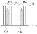
- FIG. 2 is a front view showing a state where the pouch-shaped battery cell is fixed to the jig of FIG. 1;
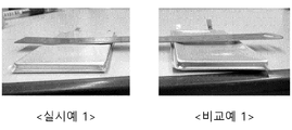
- FIG. 3 is a photograph showing a modification of the pouch type battery cell according to Example 1 and Comparative Example 1.
- Fig. 1 schematically shows a perspective view of a jig for fixing a pouch-shaped battery cell according to the present invention.
- the jig 100 comprises a substrate 111 in the form of a plate-like substrate for positioning a pouch-shaped battery cell on an upper surface thereof, supports 112 and 112 fixed in a direction perpendicular to the substrate 111 to fix the pouch- 113, 114, and 115, and a pouch-shaped battery cell receiving portion 121.
- the jig 100 has a structure in which four support portions 112, 113, 114 and 115 are formed and a support portion 112 and a support portion 113 are paired and a support portion 114 and a support portion 115 form a pair, So that the battery cells located in the battery cell accommodating portion 121 are pressed.
- the supporting portions 112 and 113 and the supporting portions 114 and 115 move in opposite directions to face each other in order to take out the battery cells after pressurization and chemical processes.
- the jig 100 illustrated in FIG. 1 has a structure including four support portions.
- the number of support portions formed on the jig used in the manufacturing method of the present invention is not particularly limited, The present invention can be embodied in the scope of the present invention.
- FIG. 2 schematically shows a front view of a state where the pouch type battery cell is fixed to the jig of FIG.
- a pouch-shaped battery cell 131 is fixed between a supporting portion 112 and a supporting portion 113, and a pouch-shaped battery cell 132 is fixed between a supporting portion 114 and a supporting portion 115 have.
- the height of the support portions 112, 113, 114, and 115 is higher than the height of the pouch-shaped battery cells 131 and 133, and the structure can press the two battery cells, A plurality of supporting portions and a battery cell accommodating portion may be formed so as to simultaneously press the plurality of battery cells.
- the electrode terminals of the battery cells 131 and 132 are fixed in the vertical direction so as to protrude upward in the battery cell accommodating portion 121. However, if the battery cells are erected in the vertical direction, have.
- the supporting portions move in directions facing each other to press the battery cells. In this state, charging and discharging of the battery cells are performed do.
- An electrode assembly having a structure in which a cathode including a cathode active material of lithium cobalt oxide and a cathode active material of silicon oxide is stacked with a separator interposed therebetween is housed in a pouch-shaped battery case, and 11 g of the electrolytic solution is poured into a pouch- Cells were prepared.
- the battery cell was fixed to the pressure jig for the jiggraining process, and the battery cell was pressurized with a pressure of 0.5 kgf / cm < 2 > Repeated all-pass process.
- the battery cell was removed from the jig, and the capacity of the battery and the remaining amount of the electrolyte were measured. The results are shown in Table 1.
- a battery cell was fabricated in the same manner as in Example 1 except that the battery cell was fixed to the pressure jig in the jigging process and then the battery cell was pressed at a pressure of 2 kgf / cm 2 .
- the prepared battery cell was taken out from the jig, and the capacity of the battery and the remaining amount of the electrolyte were measured. The results are shown in Table 1.
- a battery cell was fabricated in the same manner as in Example 1, except that the jig-grading process was not performed.
- the prepared battery cell was taken out from the jig, and the capacity of the battery and the remaining amount of the electrolyte were measured. The results are shown in Table 1.
- a battery cell was prepared in the same manner as in Example 1, except that the jig-grading process was not performed and the electrolyte solution was subjected to a general in-solution method.
- the prepared battery cell was taken out from the jig, and the capacity of the battery and the remaining amount of the electrolyte were measured. The results are shown in Table 1.
- the battery cells of Examples 1 and 2 show the remaining amount of electrolyte of 10 g or more, while the battery cells of Comparative Examples 1 and 2 show the amount of residual electrolyte of about 5 g, It can be seen that the amount of the electrolyte remaining is increased by about 100%.
- Example 3 shows photographs of the battery cells manufactured in Example 1 and Comparative Example 1, respectively.
- the battery cell has a shape in which the central portion of the battery cell is concave on a plane.
- a battery cell can be provided.
- 131, 132 pouch type battery cell
- the pouch-shaped battery cell having undergone the primary charging step for the primary charging and discharging in the state where the electrolyte is injected is placed in the pressing jig,
- the jig grading for charging / discharging the secondary battery is performed, since the battery cell is pressed by the jig, it is possible to prevent the shape of the battery cell from being deformed due to the expansion of the electrode assembly during the charging / discharging process.
- the battery cell is charged in a state where the battery cell is located in the jig, the amount of the electrolytic solution impregnated by the pores in the expanded negative electrode is increased, so that the amount of the electrolyte discharged in the degassing process is reduced, .
Landscapes
- Chemical & Material Sciences (AREA)
- Chemical Kinetics & Catalysis (AREA)
- Electrochemistry (AREA)
- General Chemical & Material Sciences (AREA)
- Engineering & Computer Science (AREA)
- Manufacturing & Machinery (AREA)
- Inorganic Chemistry (AREA)
- Materials Engineering (AREA)
- Secondary Cells (AREA)
- Battery Electrode And Active Subsutance (AREA)
- Packages (AREA)
Abstract
La présente invention concerne un procédé de fabrication d'une cellule de batterie de type poche comprenant un matériau actif d'anode à base de silicium, comprenant : (a) une étape d'injection d'une solution électrolytique dans un boîtier de batterie de type poche dans lequel est logé un ensemble d'électrodes ; (b) une étape de formation primaire consistant à charger/décharger une cellule de batterie de type poche dans laquelle la solution électrolytique est injectée ; (c) une étape de positionnement de la cellule de batterie de type poche dans un gabarit pour réaliser la fixation et la mise sous pression ; et (d) une étape de calibrage de gabarit consistant à effectuer une charge/décharge dans un état dans lequel une pression est appliquée au gabarit.
Priority Applications (4)
| Application Number | Priority Date | Filing Date | Title |
|---|---|---|---|
| EP18857023.8A EP3579323B1 (fr) | 2017-09-18 | 2018-08-27 | Procédé de fabrication d'une cellule de batterie en forme de poche comprenant un classement de gabarit |
| US16/486,689 US11075419B2 (en) | 2017-09-18 | 2018-08-27 | Method of manufacturing pouch-shaped battery cell comprising jig grading |
| ES18857023T ES2968280T3 (es) | 2017-09-18 | 2018-08-27 | Método de fabricación de una célula de batería con forma de bolsa que comprende una graduación con plantilla |
| CN201880012401.5A CN110313095A (zh) | 2017-09-18 | 2018-08-27 | 包括治具分级的制造袋形电池单体的方法 |
Applications Claiming Priority (2)
| Application Number | Priority Date | Filing Date | Title |
|---|---|---|---|
| KR10-2017-0119815 | 2017-09-18 | ||
| KR1020170119815A KR102441813B1 (ko) | 2017-09-18 | 2017-09-18 | 지그 그레이딩을 포함하는 파우치형 전지셀 제조방법 |
Publications (1)
| Publication Number | Publication Date |
|---|---|
| WO2019054666A1 true WO2019054666A1 (fr) | 2019-03-21 |
Family
ID=65722922
Family Applications (1)
| Application Number | Title | Priority Date | Filing Date |
|---|---|---|---|
| PCT/KR2018/009852 Ceased WO2019054666A1 (fr) | 2017-09-18 | 2018-08-27 | Procédé de fabrication d'une cellule de batterie de type poche, comprenant un calibrage de gabarit |
Country Status (7)
| Country | Link |
|---|---|
| US (1) | US11075419B2 (fr) |
| EP (1) | EP3579323B1 (fr) |
| KR (1) | KR102441813B1 (fr) |
| CN (1) | CN110313095A (fr) |
| ES (1) | ES2968280T3 (fr) |
| HU (1) | HUE065442T2 (fr) |
| WO (1) | WO2019054666A1 (fr) |
Cited By (1)
| Publication number | Priority date | Publication date | Assignee | Title |
|---|---|---|---|---|
| EP3975305A4 (fr) * | 2019-07-22 | 2022-08-03 | LG Energy Solution, Ltd. | Procédé de fabrication de batterie secondaire |
Families Citing this family (4)
| Publication number | Priority date | Publication date | Assignee | Title |
|---|---|---|---|---|
| KR102447619B1 (ko) | 2017-09-18 | 2022-09-27 | 주식회사 엘지에너지솔루션 | 지그를 이용한 고정 과정을 포함하는 파우치형 전지셀 제조방법 |
| JP7362189B2 (ja) | 2019-09-05 | 2023-10-17 | エルジー エナジー ソリューション リミテッド | 二次電池およびその二次電池の製造方法 |
| CN112366356B (zh) * | 2020-07-29 | 2022-04-12 | 万向一二三股份公司 | 一种改善电芯浸润效果的方法及锂离子电池电芯 |
| KR20250167256A (ko) | 2024-05-22 | 2025-12-01 | 주식회사 엘지에너지솔루션 | 파우치 전지의 활성화 방법 |
Citations (9)
| Publication number | Priority date | Publication date | Assignee | Title |
|---|---|---|---|---|
| JP2001313067A (ja) * | 2000-04-28 | 2001-11-09 | Matsushita Electric Ind Co Ltd | ニッケル水素蓄電池の製造方法およびニッケル水素蓄電池の製造装置 |
| KR100987942B1 (ko) | 2008-08-18 | 2010-10-18 | 주식회사 피앤이솔루션 | 리튬폴리머전지의 충,방전 지그 |
| JP2014035987A (ja) * | 2012-08-10 | 2014-02-24 | Toyota Motor Corp | Si含有活物質層の製造方法、固体電池の製造方法、Si含有活物質層および固体電池 |
| JP2016515291A (ja) | 2013-03-14 | 2016-05-26 | エネヴェート・コーポレーション | 電気化学セルスタックのためのクランプ装置 |
| KR20160132572A (ko) | 2015-05-11 | 2016-11-21 | 주식회사 엘지화학 | 활성화 과정 중 전극조립체를 가압하는 전지셀 제조방법 |
| KR20170019614A (ko) * | 2015-08-12 | 2017-02-22 | 주식회사 엘지화학 | 진공 생성기를 포함하는 전해액 주액 장치 및 이를 사용하여 제조된 전지셀 |
| KR20170033601A (ko) | 2015-09-17 | 2017-03-27 | 주식회사 엘지화학 | 탈기 과정의 공정성이 향상된 이차전지의 제조 방법 |
| KR20170050547A (ko) * | 2015-10-30 | 2017-05-11 | 삼성에스디아이 주식회사 | 이차전지의 전해액 함습 촉진 장치 및 이를 이용한 전해액 함습 촉진 방법 |
| KR20170119815A (ko) | 2016-04-20 | 2017-10-30 | 이성기 | 카드 한도 체크 통합 인증 서비스 제공 방법 |
Family Cites Families (21)
| Publication number | Priority date | Publication date | Assignee | Title |
|---|---|---|---|---|
| JP3457624B2 (ja) | 2000-04-14 | 2003-10-20 | 日本電気株式会社 | 扁平型電池の製造方法 |
| KR101084076B1 (ko) | 2010-05-06 | 2011-11-16 | 삼성에스디아이 주식회사 | 리튬 이차 전지용 양극 활물질 및 이를 포함하는 리튬 이차 전지 |
| KR20130126365A (ko) * | 2012-05-11 | 2013-11-20 | 주식회사 엘지화학 | 리튬 이차전지의 제조방법 |
| US20140072868A1 (en) * | 2012-05-11 | 2014-03-13 | East Penn Manufacturing Co., | Composite Current Collector and Methods Therefor |
| CN102856590B (zh) * | 2012-09-21 | 2014-11-26 | 深圳市美拜电子有限公司 | 一种锂离子二次电池的化成分容方法 |
| KR101578510B1 (ko) * | 2012-10-18 | 2015-12-18 | 주식회사 엘지화학 | 수명특성이 향상된 리튬 이차전지 |
| KR101629482B1 (ko) | 2013-07-31 | 2016-06-10 | 주식회사 엘지화학 | 활성화 공정 중 전지를 가압하는 리튬 이차전지의 제조방법 |
| KR101569056B1 (ko) * | 2013-10-07 | 2015-11-16 | 주식회사 엘지화학 | 규소계 화합물을 포함하는 이차전지 |
| CN103560218B (zh) * | 2013-10-16 | 2016-01-13 | 广州力柏能源科技有限公司 | 电池安全阀装置及其电池及其制作方法 |
| CN103779600B (zh) * | 2013-12-19 | 2016-08-17 | 宁波维科电池股份有限公司 | 一种钛酸锂电池及制造方法 |
| KR101704760B1 (ko) | 2014-01-08 | 2017-02-08 | 주식회사 엘지화학 | 가압 트레이 |
| CN103855431B (zh) * | 2014-03-24 | 2016-06-29 | 四川剑兴锂电池有限公司 | 一种提高锂离子电池循环性能的化成方法 |
| CN204011573U (zh) * | 2014-06-20 | 2014-12-10 | 东莞新能源科技有限公司 | 一种锂离子电池的封装装置 |
| JP2016081790A (ja) | 2014-10-20 | 2016-05-16 | トヨタ自動車株式会社 | 全固体二次電池の製造方法 |
| KR102311507B1 (ko) * | 2014-11-11 | 2021-10-12 | 삼성에스디아이 주식회사 | 리튬 이차 전지용 음극 및 이를 포함하는 리튬 이차 전지 |
| US9620830B2 (en) * | 2014-12-16 | 2017-04-11 | Xinen Technology Hong Kong Company, Ltd. | Vehicle battery module with cooling and safety features |
| JP6183398B2 (ja) * | 2015-03-30 | 2017-08-23 | トヨタ自動車株式会社 | 非水電解液二次電池およびその製造方法 |
| KR20170021213A (ko) * | 2015-08-17 | 2017-02-27 | 주식회사 엘지화학 | 이차전지의 제작방법 |
| KR102170026B1 (ko) | 2015-09-21 | 2020-10-26 | 주식회사 엘지화학 | 저온 특성이 향상된 리튬 이차전지의 제조방법 및 리튬 이차전지 |
| KR102164460B1 (ko) * | 2015-12-09 | 2020-10-12 | 주식회사 엘지화학 | 가압 트레이 |
| CN106058322B (zh) * | 2016-07-29 | 2019-04-26 | 深圳市宜加新能源科技有限公司 | 一种高倍率动力电池的制作方法 |
-
2017
- 2017-09-18 KR KR1020170119815A patent/KR102441813B1/ko active Active
-
2018
- 2018-08-27 EP EP18857023.8A patent/EP3579323B1/fr active Active
- 2018-08-27 CN CN201880012401.5A patent/CN110313095A/zh active Pending
- 2018-08-27 ES ES18857023T patent/ES2968280T3/es active Active
- 2018-08-27 WO PCT/KR2018/009852 patent/WO2019054666A1/fr not_active Ceased
- 2018-08-27 HU HUE18857023A patent/HUE065442T2/hu unknown
- 2018-08-27 US US16/486,689 patent/US11075419B2/en active Active
Patent Citations (9)
| Publication number | Priority date | Publication date | Assignee | Title |
|---|---|---|---|---|
| JP2001313067A (ja) * | 2000-04-28 | 2001-11-09 | Matsushita Electric Ind Co Ltd | ニッケル水素蓄電池の製造方法およびニッケル水素蓄電池の製造装置 |
| KR100987942B1 (ko) | 2008-08-18 | 2010-10-18 | 주식회사 피앤이솔루션 | 리튬폴리머전지의 충,방전 지그 |
| JP2014035987A (ja) * | 2012-08-10 | 2014-02-24 | Toyota Motor Corp | Si含有活物質層の製造方法、固体電池の製造方法、Si含有活物質層および固体電池 |
| JP2016515291A (ja) | 2013-03-14 | 2016-05-26 | エネヴェート・コーポレーション | 電気化学セルスタックのためのクランプ装置 |
| KR20160132572A (ko) | 2015-05-11 | 2016-11-21 | 주식회사 엘지화학 | 활성화 과정 중 전극조립체를 가압하는 전지셀 제조방법 |
| KR20170019614A (ko) * | 2015-08-12 | 2017-02-22 | 주식회사 엘지화학 | 진공 생성기를 포함하는 전해액 주액 장치 및 이를 사용하여 제조된 전지셀 |
| KR20170033601A (ko) | 2015-09-17 | 2017-03-27 | 주식회사 엘지화학 | 탈기 과정의 공정성이 향상된 이차전지의 제조 방법 |
| KR20170050547A (ko) * | 2015-10-30 | 2017-05-11 | 삼성에스디아이 주식회사 | 이차전지의 전해액 함습 촉진 장치 및 이를 이용한 전해액 함습 촉진 방법 |
| KR20170119815A (ko) | 2016-04-20 | 2017-10-30 | 이성기 | 카드 한도 체크 통합 인증 서비스 제공 방법 |
Cited By (2)
| Publication number | Priority date | Publication date | Assignee | Title |
|---|---|---|---|---|
| EP3975305A4 (fr) * | 2019-07-22 | 2022-08-03 | LG Energy Solution, Ltd. | Procédé de fabrication de batterie secondaire |
| US12573674B2 (en) | 2019-07-22 | 2026-03-10 | Lg Energy Solution, Ltd. | Method of manufacturing secondary battery |
Also Published As
| Publication number | Publication date |
|---|---|
| KR102441813B1 (ko) | 2022-09-08 |
| HUE065442T2 (hu) | 2024-05-28 |
| US20190372062A1 (en) | 2019-12-05 |
| ES2968280T3 (es) | 2024-05-08 |
| EP3579323A1 (fr) | 2019-12-11 |
| KR20190031856A (ko) | 2019-03-27 |
| CN110313095A (zh) | 2019-10-08 |
| US11075419B2 (en) | 2021-07-27 |
| EP3579323B1 (fr) | 2023-10-18 |
| EP3579323A4 (fr) | 2020-01-15 |
Similar Documents
| Publication | Publication Date | Title |
|---|---|---|
| WO2019054837A1 (fr) | Procédé de fabrication d'une cellule de batterie de type poche au moyen d'un gabarit, comprenant une étape de fixation | |
| WO2019031744A1 (fr) | Procédé de pré-lithiation d'anode de batterie secondaire | |
| KR101607024B1 (ko) | 리튬 이차전지 | |
| WO2018212453A1 (fr) | Procédé de pré-lithiation d'anode d'oxyde de silicium destinée à une batterie secondaire | |
| KR102019312B1 (ko) | 겔 폴리머 전해질용 조성물 및 이를 포함하는 리튬 이차전지 | |
| WO2019088672A1 (fr) | Matériau actif d'anode destiné à un dispositif électrochimique, anode comportant ledit matériau actif d'anode et dispositif électrochimique comportant ladite anode | |
| WO2020105974A1 (fr) | Procédé d'activation d'une batterie secondaire | |
| WO2019013500A2 (fr) | Batterie secondaire au lithium et son procédé de fabrication | |
| WO2020159236A1 (fr) | Procédé de pré-lithiation d'électrode négative pour batterie secondaire | |
| WO2019054666A1 (fr) | Procédé de fabrication d'une cellule de batterie de type poche, comprenant un calibrage de gabarit | |
| WO2015102140A1 (fr) | Anode pour batterie rechargeable, et batterie rechargeable au lithium comprenant cette dernière | |
| WO2020071814A1 (fr) | Anode à structure multicouche comprenant un composé à base de silicium, et batterie secondaire au lithium la comprenant | |
| WO2015102139A1 (fr) | Électrode négative pour batterie secondaire et batterie secondaire au lithium comprenant celle-ci | |
| WO2017061807A1 (fr) | Élément de batterie comprenant un composant d'électrolyte gélifié dans un pore d'air de film de séparation constituant un ensemble électrode | |
| WO2020251165A1 (fr) | Procédé de fabrication de batterie secondaire au lithium comprenant une étape de traitement thermique supplémentaire et batterie secondaire au lithium fabriquée par ce moyen | |
| WO2020149668A1 (fr) | Procédé de charge d'un accumulateur qui réduit le temps de charge | |
| WO2016209014A1 (fr) | Procédé permettant de fabriquer une batterie rechargeable au lithium et batterie rechargeable au lithium fabriquée à l'aide de ce dernier | |
| WO2019017617A1 (fr) | Électrode n'ayant pas de collecteur de courant et accumulateur la comprenant | |
| KR102926682B1 (ko) | 양극 활물질, 이의 제조방법 및 이를 포함하는 리튬이차전지 | |
| KR20150047052A (ko) | 양극 활물질, 이의 제조방법, 및 이를 포함하는 리튬 이차전지 | |
| WO2019022541A2 (fr) | Électrode positive pour batterie rechargeable au lithium et batterie rechargeable au lithium comprenant celle-ci | |
| WO2024080613A1 (fr) | Électrolyte composite, son procédé de préparation et batterie secondaire au lithium le comprenant | |
| WO2021215622A1 (fr) | Électrolyte pour batterie au lithium métallique et batterie au lithium métallique le comprenant | |
| WO2019013478A2 (fr) | Procédé de fabrication de batterie secondaire utilisant du lithium métallique en tant qu'électrode négative | |
| WO2022045809A1 (fr) | Procédé de pré-lithiation d'anode |
Legal Events
| Date | Code | Title | Description |
|---|---|---|---|
| 121 | Ep: the epo has been informed by wipo that ep was designated in this application |
Ref document number: 18857023 Country of ref document: EP Kind code of ref document: A1 |
|
| ENP | Entry into the national phase |
Ref document number: 2018857023 Country of ref document: EP Effective date: 20190906 |
|
| NENP | Non-entry into the national phase |
Ref country code: DE |