WO2019058529A1 - Machine de montage de composant et procédé de relance pour saisir des composants - Google Patents
Machine de montage de composant et procédé de relance pour saisir des composants Download PDFInfo
- Publication number
- WO2019058529A1 WO2019058529A1 PCT/JP2017/034375 JP2017034375W WO2019058529A1 WO 2019058529 A1 WO2019058529 A1 WO 2019058529A1 JP 2017034375 W JP2017034375 W JP 2017034375W WO 2019058529 A1 WO2019058529 A1 WO 2019058529A1
- Authority
- WO
- WIPO (PCT)
- Prior art keywords
- component
- retry
- suction nozzle
- unit
- suction
- Prior art date
- Legal status (The legal status is an assumption and is not a legal conclusion. Google has not performed a legal analysis and makes no representation as to the accuracy of the status listed.)
- Ceased
Links
Images



Classifications
-
- H—ELECTRICITY
- H05—ELECTRIC TECHNIQUES NOT OTHERWISE PROVIDED FOR
- H05K—PRINTED CIRCUITS; CASINGS OR CONSTRUCTIONAL DETAILS OF ELECTRIC APPARATUS; MANUFACTURE OF ASSEMBLAGES OF ELECTRICAL COMPONENTS
- H05K13/00—Apparatus or processes specially adapted for manufacturing or adjusting assemblages of electric components
- H05K13/04—Mounting of components, e.g. of leadless components
- H05K13/0404—Pick-and-place heads or apparatus, e.g. with jaws
- H05K13/0408—Incorporating a pick-up tool
- H05K13/0409—Sucking devices
-
- H—ELECTRICITY
- H05—ELECTRIC TECHNIQUES NOT OTHERWISE PROVIDED FOR
- H05K—PRINTED CIRCUITS; CASINGS OR CONSTRUCTIONAL DETAILS OF ELECTRIC APPARATUS; MANUFACTURE OF ASSEMBLAGES OF ELECTRICAL COMPONENTS
- H05K13/00—Apparatus or processes specially adapted for manufacturing or adjusting assemblages of electric components
- H05K13/04—Mounting of components, e.g. of leadless components
- H05K13/0404—Pick-and-place heads or apparatus, e.g. with jaws
- H05K13/0408—Incorporating a pick-up tool
- H05K13/041—Incorporating a pick-up tool having multiple pick-up tools
-
- H—ELECTRICITY
- H05—ELECTRIC TECHNIQUES NOT OTHERWISE PROVIDED FOR
- H05K—PRINTED CIRCUITS; CASINGS OR CONSTRUCTIONAL DETAILS OF ELECTRIC APPARATUS; MANUFACTURE OF ASSEMBLAGES OF ELECTRICAL COMPONENTS
- H05K13/00—Apparatus or processes specially adapted for manufacturing or adjusting assemblages of electric components
- H05K13/04—Mounting of components, e.g. of leadless components
- H05K13/0417—Feeding with belts or tapes
-
- H—ELECTRICITY
- H05—ELECTRIC TECHNIQUES NOT OTHERWISE PROVIDED FOR
- H05K—PRINTED CIRCUITS; CASINGS OR CONSTRUCTIONAL DETAILS OF ELECTRIC APPARATUS; MANUFACTURE OF ASSEMBLAGES OF ELECTRICAL COMPONENTS
- H05K13/00—Apparatus or processes specially adapted for manufacturing or adjusting assemblages of electric components
- H05K13/08—Monitoring manufacture of assemblages
- H05K13/081—Integration of optical monitoring devices in assembly lines; Processes using optical monitoring devices specially adapted for controlling devices or machines in assembly lines
- H05K13/0812—Integration of optical monitoring devices in assembly lines; Processes using optical monitoring devices specially adapted for controlling devices or machines in assembly lines the monitoring devices being integrated in the mounting machine, e.g. for monitoring components, leads, component placement
-
- H—ELECTRICITY
- H05—ELECTRIC TECHNIQUES NOT OTHERWISE PROVIDED FOR
- H05K—PRINTED CIRCUITS; CASINGS OR CONSTRUCTIONAL DETAILS OF ELECTRIC APPARATUS; MANUFACTURE OF ASSEMBLAGES OF ELECTRICAL COMPONENTS
- H05K13/00—Apparatus or processes specially adapted for manufacturing or adjusting assemblages of electric components
- H05K13/08—Monitoring manufacture of assemblages
- H05K13/081—Integration of optical monitoring devices in assembly lines; Processes using optical monitoring devices specially adapted for controlling devices or machines in assembly lines
- H05K13/0813—Controlling of single components prior to mounting, e.g. orientation, component geometry
-
- H—ELECTRICITY
- H05—ELECTRIC TECHNIQUES NOT OTHERWISE PROVIDED FOR
- H05K—PRINTED CIRCUITS; CASINGS OR CONSTRUCTIONAL DETAILS OF ELECTRIC APPARATUS; MANUFACTURE OF ASSEMBLAGES OF ELECTRICAL COMPONENTS
- H05K13/00—Apparatus or processes specially adapted for manufacturing or adjusting assemblages of electric components
- H05K13/08—Monitoring manufacture of assemblages
- H05K13/082—Integration of non-optical monitoring devices, i.e. using non-optical inspection means, e.g. electrical means, mechanical means or X-rays
-
- H—ELECTRICITY
- H05—ELECTRIC TECHNIQUES NOT OTHERWISE PROVIDED FOR
- H05K—PRINTED CIRCUITS; CASINGS OR CONSTRUCTIONAL DETAILS OF ELECTRIC APPARATUS; MANUFACTURE OF ASSEMBLAGES OF ELECTRICAL COMPONENTS
- H05K13/00—Apparatus or processes specially adapted for manufacturing or adjusting assemblages of electric components
- H05K13/08—Monitoring manufacture of assemblages
- H05K13/0882—Control systems for mounting machines or assembly lines, e.g. centralized control, remote links, programming of apparatus and processes as such
Definitions
- the present specification relates to a component mounting machine that carries out a mounting operation of mounting an electronic component (hereinafter, abbreviated as a component) to a substrate.
- a component an electronic component
- the component placement machine generally includes a substrate transfer device, a component supply device, and a component transfer device.
- the component transfer device includes a mounting head for holding a suction nozzle, and a head drive mechanism for driving the mounting head in two horizontal directions.
- a retry operation is often performed on expensive parts.
- Patent Literatures 1 and 2 disclose technical examples relating to a retry operation of component suction.
- JP 2008-53382 A Japanese Patent Application Laid-Open No. 10-163686
- Patent Document 1 By the way, some customers collect and use parts that were not collected from used carrier tape, and reduce the waste rate.
- the technique of Patent Document 1 is preferable in that waste of parts can be reduced by the retry operation, and time and effort for part collection can be omitted.
- a meaningless retry operation may be performed.
- several cavities near the front end and the rear end of the carrier tape are empty cavities where no parts are stored from the beginning.
- the meaningless retry operation on the empty cavity lowers the production efficiency of the component mounting machine.
- Such problems are not limited to the combination of the suction nozzle and the carrier tape, and it is necessary to consider other types of component mounting tools and other types of component supply media.
- the present specification is a component mounting apparatus including a component supply device for supplying components to a supply position, and a component transfer device for collecting the components from the supply position using a component mounting tool and mounting the components on a substrate.
- a part detection unit for detecting whether or not the part is present at the supply position
- a retry operation for collecting the component again using the component mounting tool based on the holding detection unit that detects whether the component is held, the detection result of the component detection unit, and the detection result of the holding detection unit.
- a component placement machine comprising: a retry execution unit that determines whether or not to carry out and performs the retry operation based on the determination result.
- the present specification also provides a component mounting apparatus including a component supply device for supplying a component to a supply position, and a component transfer device for extracting the component from the supply position using a component mounting tool and mounting the component on a substrate.
- a method for retrying parts collection in the part the parts detection step of detecting whether or not the parts are present at the supply position before or when the parts are collected using the parts mounting tool, and the parts Based on the holding detection step of detecting whether or not the mounting tool picks up and holds the component, the detection result of the component detection step, and the detection result of the holding detection step, using the component mounting tool again It is determined whether or not a retry operation for collecting the part is to be performed, and a retry execution step for performing the retry operation based on the determination result, and a retry method for part collection is disclosed.
- the component mounting machine disclosed in the present specification it is detected whether or not there is a component in the supply position before or when the component mounting tool is used to sample the component, and the component mounting tool further holds the component. It is determined whether or not to perform the retry operation based on the detection result. Therefore, meaningless retry operation can be avoided when there are no parts at the supply position from the beginning. Further, according to the part sampling retry method disclosed in the present specification, the same effects as those of the component mounting machine described above can be obtained.
- FIG. 1 It is a top view which shows typically the structure of the component mounting machine of embodiment. It is a block diagram which shows the structure of control of the component mounting machine of embodiment. It is a figure which illustrates the situation of adsorption operation of parts, and is a top view showing typically a feeder device and a small mounting head of a parts transfer device. It is a figure which illustrates typically height when three types of mounting heads move to a horizontal direction. It is a flowchart which shows the main operation
- FIG. 1 is a top view which shows typically the structure of the components mounting machine 1 of embodiment.
- the direction from the left side to the right side of the drawing of FIG. 1 is the X-axis direction for transporting the substrate K, and the direction from the lower side to the upper side of the drawing is the Y-axis direction (front-rear direction).
- FIG. 2 is a block diagram showing a control configuration of the component mounting machine 1 of the embodiment.
- the component placement machine 1 is configured by assembling a substrate transfer device 2, a component supply device 3, a component transfer device 4, a component camera 5, a control device 6 and the like to the machine base 10.
- the substrate transfer device 2, the component supply device 3, the component transfer device 4, and the component camera 5 are controlled by the control device 6 and take charge of predetermined operations.
- the substrate transfer apparatus 2 is in charge of the transfer operation and the positioning operation of the substrate K.
- the substrate transfer apparatus 2 comprises a transfer unit 25 and a backup unit 26.
- the transport unit 25 includes a pair of guide rails 21 and 22 and a pair of conveyor belts.
- the pair of guide rails 21 and 22 extend in the X-axis direction at the center of the upper surface of the machine base 10 and are arranged parallel to each other.
- a pair of endless endless conveyor belts (not shown) is provided on the inside of the pair of guide rails 21 and 22 facing each other.
- the pair of conveyor belts are rotated in a state where the opposite sides of the rectangular substrate K are placed, and the substrate K is carried into and out of the mounting implementation position set at the central portion of the machine base 10.
- the backup unit 26 is disposed below the mounting implementation position.
- the backup unit 26 pushes up the substrate K, clamps it in a horizontal posture, and positions it at the mounting implementation position. As a result, the component transfer device 4 can perform the mounting operation
- the parts supply device 3 is in charge of parts supply work.
- the parts supply device 3 includes a pallet table 30 and a plurality of feeder devices 31 and the like.
- the pallet table 30 has a substantially rectangular plate shape, and is detachably mounted on the front side of the upper surface of the machine base 10.
- the feeder device 31 is formed thin in the width direction, and is arranged side by side on the pallet table 30.
- Four feeder devices 31 are illustrated in FIG. 1, and in practice, a larger number of feeder devices 31 are juxtaposed.
- the feeder apparatus 31 is appropriately replaced or the whole of the parts supply apparatus 3 is replaced.
- the feeder device 31 includes a main body portion 32 and a tape reel 33 set exchangeably on the front side of the main body portion 32.
- a supply position 34 is set at the upper part near the rear end of the main body 32.
- a carrier tape 9 (see FIG. 3) as a component supply medium is wound and held.
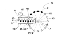
- FIG. 3 is a view illustrating the state of the suction operation of the component P, and is a plan view schematically showing the feeder device 31 and the small mounting head 45 of the component transfer device 4. In FIG. 3, the part P is shown in black.
- the carrier tape 9 is composed of a bottom tape 91 and a cover tape 92 attached to the bottom tape 91.
- the bottom tape 91 is made of paper or resin, and the cavity portion 93 for housing the component P is formed at a constant pitch.
- the cover tape 92 is made of a transparent film or the like and covers the cavity 93.
- the feeder device 31 feeds the carrier tape 9 at a constant pitch and advances the cavity 93 to the supply position 34 one by one.
- the cover tape 92 is peeled from the bottom tape 91 and bent by a peeling mechanism (not shown). As a result, the component P can be taken out of the cavity 93 of the supply position 34.
- the component transfer device 4 takes charge of the component mounting operation.
- the component transfer device 4 is an XY robot type device capable of horizontally moving in the X-axis direction and the Y-axis direction.
- the component transfer device 4 includes a pair of Y-axis rails 41 and 42, a Y-axis slider 43, an X-axis slider 44, a plurality of selectively mountable mounting heads (45 to 47), a substrate camera 48, etc. .
- the pair of Y-axis rails 41 and 42 are disposed on both sides of the machine base 10 and extend in the Y-axis direction.
- the Y-axis slider 43 is movably mounted on the Y-axis rails 41 and 42.
- the Y-axis slider 43 is driven in the Y-axis direction by a Y-axis ball screw mechanism 431.
- the X-axis slider 44 is movably mounted on the Y-axis slider 43.
- the X-axis slider 44 is driven in the X-axis direction by an X-axis ball screw mechanism 441.
- the X-axis slider 44 includes a head elevating device 445 that raises and lowers the mounting head (45 to 47) with respect to the X-axis slider 44.
- a head elevating device 445 that raises and lowers the mounting head (45 to 47) with respect to the X-axis slider 44.
- a small mounting head 45, a medium mounting head 46, and a large mounting head 47 are used as a plurality of types of mounting heads (45 to 47). These mounting heads (45 to 47) are arranged side by side at a head exchange station 11 on the machine base 10. Then, the mounting head (45 to 47) is vertically moved by the head lifting device 445, and the mounting head (45 to 47) is automatically replaced.
- FIG. 1 illustrates the state in which the small mounting head 45
- the small mounting head 45 includes a rotary tool 451, a small suction nozzle 452, a rotation driving unit 453, an elevation driving unit 454, an internal pressure control unit 455, a negative pressure measurement sensor 456, a side view camera 457, and the like.
- the rotary tool 451 is rotatably held below the small mounting head 45.
- Sixteen nozzle holders are annularly disposed on the rotary tool 451 at intervals of a predetermined angle A. Each nozzle holder holds the 16 small suction nozzles 452 vertically movably via an elastic member.
- the 16 small suction nozzles 452 are in charge of mounting the small parts P.
- the suction position 459 is a position directly above the supply position 34 of the feeder device 31.
- the elevation drive unit 454 raises and lowers the nozzle holder at the suction position 459.
- the internal pressure control unit 455 supplies a negative pressure to the small suction nozzle 452 concerned.
- the negative pressure measurement sensor 456 measures the negative pressure inside the small suction nozzle 452 when the small suction nozzle 452 is performing suction operation.
- suction of atmospheric air is prevented, and the negative pressure of the small suction nozzle 452 is significantly reduced. If the part P does not exist, suction of atmospheric air continues, so the negative pressure of the small-sized adsorption nozzle 452 does not decrease much. Therefore, the presence or absence of the component P is detected based on the measurement result of the negative pressure measurement sensor 456.
- the negative pressure measurement sensor 456 functions as a part of a component detection unit 71 and a residual detection unit 73 described later.
- the rotary drive unit 453 rotates the rotary tool 451 clockwise by a predetermined angle A (see FIG. 3).
- the first small suction nozzle 452 is rotationally moved from the suction position 459 and positioned at the detection position 458.
- the second small suction nozzle 452 next to the first small suction nozzle 452 is positioned at the suction position 459.
- the upward movement of the first small suction nozzle 452 and the rotation of the rotary tool 451 may temporally overlap.
- the suction operation of the small suction nozzle 452 described above and the rotation operation of the rotary tool 451 are repeatedly performed. As a result, the 16 or a part of the small suction nozzles 452 suction and hold the component P.
- suction of the component P by the four small suction nozzles 452 has already been completed, and suction of the component P by the fifth small suction nozzle 452 is performed.
- the rotation drive unit 453 further has a function of rotationally driving the rotary tool 451 counterclockwise in the reverse direction. According to this, the small suction nozzle 452 can be returned from the detection position 458 to the suction position 459 in a short time by a retry operation described later.
- the side-view camera 457 is disposed at a position where it can capture an image near the lower end opening of the first small suction nozzle 452 located at the detection position 458.
- the side-view camera 457 captures an image of the first small suction nozzle 452 from the side and processes the acquired image data to determine whether the first small suction nozzle 452 sucks the component P or not. It is a captured image processing unit to detect.
- the side-view camera 457 functions as part of the holding and detecting unit 72 described later. Further, when the small mounting head 45 is driven to the upper side of the substrate K, the small suction nozzle 452 at the suction position 459 is driven to be lowered by the elevation drive unit 454 and a positive pressure is supplied from the internal pressure control unit 455. Is mounted on the substrate K.
- the medium-sized mounting head 46 and the large-sized mounting head 47 are also similar in configuration to the small-sized mounting head 45.
- the middle mounting head 46 has four middle suction nozzles 462.
- the medium suction nozzle 462 is responsible for mounting the medium part P.
- the large mounting head 47 has two large suction nozzles 472.
- the large suction nozzle 472 is responsible for mounting the large part P.
- the combination of the mounting head (45, 46, 47), the suction nozzle (452, 462, 472), and the part P corresponds to small size, medium size, and large size, respectively. .
- the sizes of the parts P are various, and the mounting heads (45, 46, 47) and the suction nozzles (452, 462, 472) are often three or more in many cases.
- there is a variation in usage such as a configuration in which only the suction nozzles (452, 462, 472) are replaced without replacing the mounting heads (45, 46, 47).
- the substrate camera 48 is provided downward at a position aligned with the mounting head (45, 46, 47) of the X-axis slider 44.
- the substrate camera 48 picks up a position reference mark attached to the substrate K to detect the accurate position of the substrate K.
- the substrate camera 48 can also function as part of a component detection unit 71 and a remaining detection unit 73 described later.
- the component transfer device 4 proceeds with the mounting operation by repeating a suction mounting cycle (hereinafter referred to as a PP cycle).
- the component transfer device 4 first moves the mounting head (45, 46, 47) to the component supply device 3, and a plurality of suction nozzles (452, 462, 472) are used. Each suctions the component P.
- the component transfer device 4 then moves the mounting head (45, 46, 47) above the component camera 5. At this time, the holding state of the plurality of components P is imaged by the component camera 5.
- the component transfer device 4 moves the mounting head (45, 46, 47) to the substrate K to mount the plurality of components P, and returns to the component supply device 3 again.
- the small-sized mounting head 45, the medium-sized mounting head 46, and the large-sized mounting head 47 are automatically replaced according to the size of the component P mounted on the substrate K. For example, when mounting small and large components P on a certain type of substrate K, the small mounting head 45 and the large mounting head 47 are automatically replaced in the middle of the mounting operation on one substrate K. Used. As a general mounting sequence, several PP cycles of the small mounting head 45 are first, then PP cycles of the medium mounting head 46, and finally PP cycles of the large mounting head 47. However, depending on the type of the substrate K and the part P, there are exceptions in the mounting order.
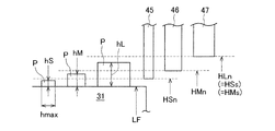
- FIG. 4 is a view schematically illustrating the heights of three types of mounting heads (45, 46, 47) moving in the horizontal direction.
- the height level LF represents the height of the top surface of the feeder device 31.
- the component P dropped accidentally during the suction operation often stays on the upper surface of the feeder device 31.
- the mounting head (45, 46, 47) may be damaged by interfering with the part P dropped when moving.
- the component P sucked by the suction nozzle (452, 462, 472) may collide with the dropped component P.
- the normal height HSn at which the lower end portion of the small mounting head 45 moves in the horizontal direction is set to be slightly higher than the height level LF in consideration of the height dimension hS of the small part P.
- the bottom of the component P adsorbed by the small suction nozzle 452 is the lower end portion, but is not limited thereto.
- the long side dimension hmax of the component P may be taken into consideration instead of the height dimension hS in the mounting posture of the small component P. According to this, even if the dropped part P is in the standing state, there is no fear of interference, and the reliability is further enhanced.
- the normal height HMn of the medium-sized mounting head 46 is set to be slightly higher than the height that takes into consideration the height dimension hM of the medium-sized part P at the height level LF.
- the normal height HLn of the large mounting head 47 is set to be slightly higher than the height at which the height dimension hL of the large part P is taken into consideration at the height level LF.
- the setting of the heights (HSn, HMn, HLn) is usually performed in conjunction with the automatic replacement of the mounting heads (45, 46, 47).
- the mounting head (45, 46, 47) When the mounting head (45, 46, 47) is not automatically replaced during the mounting operation due to the setting of the normal height (HSn, HMn, HLn), the mounting head (45, 46, 47) and the dropped part P and Interference is prevented. However, when the mounting heads (45, 46, 47) are automatically replaced, the possibility of interference is not eliminated. For example, the small mounting head 45 normally interferes with the dropped middle or large parts P when moving at the height HSn. Also, for example, when moving at the height HMn, the medium-sized mounting head 46 interferes with the dropped large part P.
- the retraction height HSs is set to the small-sized mounting head 45, and the retraction height HMs is set to the middle-sized mounting head 46.
- the retraction height HSs and the retraction height HMs are heights that can eliminate the possibility of interference regardless of the size of the dropped part P.
- the withdrawal height HSs and the withdrawal height HMs are set equal to the normal height HLn of the large mounting head 47. Further, with regard to the large-sized mounting head 47, since there is usually no fear of interference at the height HLn, the withdrawal height is not set.
- the evacuation control unit 75 described later may set the evacuation height variably in consideration of the size of the dropped part P. The switching between the normal height (HSn, HMn, HLn) and the retracted height (HSs, HMs) is performed by the retraction control unit 75 controlling the head lifting device 445.
- the component camera 5 is provided upward on the upper surface of the machine base 10 between the substrate transfer device 2 and the component supply device 3.
- the component camera 5 images the state of the component P held by the suction nozzle (452, 462, 472) while the mounting head (45, 46, 47) moves from the component supply device 3 to the substrate K. If an error in the holding attitude of the component P, a shift in the rotation angle, or the like is determined by image processing of the acquired imaging data, the control device 6 finely adjusts the mounting operation as necessary, and the mounting operation is difficult. Control to discard the part P concerned.
- the control device 6 is assembled to the machine base 10, and the arrangement position thereof is not particularly limited.
- the control device 6 is a computer device having a CPU and operating with software. As shown in FIG. 2, the control device 6 holds the mounting sequence 62 in the storage unit 61.
- the mounting sequence 62 is data specifying the type of the component P to be mounted on the substrate K, the mounting coordinate position, the mounting order, the feeder device 31 for supplying the component, and the like.
- the control device 6 controls the flow of work of the component mounting machine 1 in accordance with the mounting sequence 62. Further, the control device 6 sequentially collects and updates operation status data such as the production number of the substrates K for which production has been completed, the mounting time required for mounting the components P, and the number of suction errors of the components P.
- the control device 6 is communicably connected to a host computer 69 which is a higher-level control device, and sends and receives commands and responses.
- control device 6 performs control related to the drop determination of the component P and control related to the retry operation when the component P can not be adsorbed.
- the control device 6 includes a component detection unit 71 and a holding detection unit 72 as functional units related to both the drop determination and the retry operation.
- the control device 6 includes a remaining detection unit 73, a drop determination unit 74, a retraction control unit 75, and a retraction operation notification unit 76 as functional units related to the drop determination.
- the control device 6 includes a retry performing unit 77, a coping method setting unit 78, and a component type registration unit 79 as functional units related to the retry operation.
- the component detection unit 71 detects whether or not the component P is present at the supply position 34 of the feeder device 31 when the component P is suctioned using the suction nozzles (452, 462, 472). In the present embodiment, the component detection unit 71 uses the above-described negative pressure measurement sensor 456 to detect whether or not there is a component P in the cavity 93 located at the supply position 34.
- the configuration of the component detection unit 71 is not limited to this, and there are several other aspects.
- the component detection unit 71 measures the relative heights of the suction nozzles (452, 462, 472) with respect to the nozzle holder, and detects that the suction nozzles (452, 462, 472) are in contact with the component P.
- Height measuring sensor More specifically, when the suction nozzle (452, 462, 472) comes in contact with the component P while the nozzle holder is being lowered, the nozzle holder will not be lowered thereafter, and only the nozzle holder is continuously lowered. For this reason, the relative height of the suction nozzle (452, 462, 472) with respect to the nozzle holder changes. Therefore, the height measurement sensor can detect the presence of the part P by changing the relative height.
- the light shielding sensor provided in the nozzle holder can be illustrated.
- the light shielding sensor detects a light shielding portion provided at a specific height of the suction nozzle (452, 462, 472) to detect a change in relative height.
- the component detection unit 71 may image the cavity 93 using the substrate camera 48 before suctioning the component P, and detect the presence or absence of the component P by image processing of the acquired image data.
- the holding and detecting unit 72 detects whether or not the suction nozzles (452, 462, 472) suction and hold the component P. For example, when the small mounting head 45 is attached, the holding detection unit 72 determines whether the small suction nozzle 452 located at the detection position 458 holds the component P, using the side-view camera 457 described above. To detect.
- the remaining detection unit 73 determines whether the component P remains at the supply position 34. To detect.
- the remaining detection unit 73 is also used as the component detection unit 71, and operates in the same manner as the component detection unit 71. In practice, the detection result of “presence / absence of the part P” of the part detection unit 71 is diverted to the detection result of “the part P remains / does not remain” of the remaining detection unit 73.
- the drop determination unit 74 determines whether the component P has dropped based on the detection result of the component detection unit 71, the detection result of the holding detection unit 72, and the detection result of the remaining detection unit 73. Specifically, the component detection unit 71 detects that the component P is present at the supply position 34, and the holding detection unit 72 detects that the suction nozzle (452, 462, 472) does not hold the component P. Furthermore, when it is detected by the remaining detection unit 73 that the component P does not remain at the supply position 34, the drop determination unit 74 determines that the component P has dropped.
- the component detection unit 71, the holding detection unit 72, the remaining detection unit 73, and the drop determination unit 74 use the component P having a predetermined size or more as the target of the drop determination. Specifically, medium-sized and large-sized parts P are targeted for drop determination, and small-sized parts P that do not interfere even if dropped, are excluded. As a result, the time required for detection and determination is reduced, and the production efficiency is improved.
- the nozzle holder is lowered to a position lower than the normal position for the purpose of making the change in relative height apparent.
- the nozzle holder may be lowered to the normal position, and the time required for detection is reduced.
- the component detection unit 71 includes the substrate camera 48, the time for imaging and processing the cavity portion 93 in which the small component P is accommodated is reduced.
- the retraction control unit 75 controls a retraction operation to move the mounting head (45, 46) at the retraction height (HSs, HMs). Furthermore, the retraction control unit 75 is configured to include the type of suction nozzle (452, 462, 472), the type of mounting head (45, 46, 47), the size of the dropped part P, and the size of the part P to be sucked from this. Based on at least one item, it is determined whether or not the evacuation operation is necessary.
- the evacuation operation notification unit 76 notifies at least one of the host computer 69 and the operator of the control execution state of the evacuation control unit 75. This notification enables early handling, the dropped parts P are recovered, and high production efficiency at normal height (HSn, HMn) is recovered.
- the retry execution unit 77 Based on the detection result of the component detection unit 71 and the detection result of the holding detection unit 72, the retry execution unit 77 performs a retry operation to suction the component P again using the suction nozzles (452, 462, 472). Determine if Furthermore, the retry performing unit 77 performs a retry operation based on the determination result.
- the component detection unit 71 detects that the component P is present at the supply position 34, and the holding detection unit 72 detects that the suction nozzle (452, 462, 472) does not hold the component P.
- the retry performing unit 77 performs the retry operation on the same cavity portion 93 as the first suction operation. Furthermore, the retry performing unit 77 performs the retry operation up to a predetermined number of times N when the component P can not be adsorbed by one retry operation.
- the coping method setting part 78 is a coping method when the suction nozzle (452, 462, 472) can not suck the part P even if the retrying part 77 performs the retry operation, that is, the coping method when the retry operation is unsuccessful.
- Skip the mounting operation is ended without mounting the part P, and the history of the skip is recorded.
- alert an alarm is notified while proceeding with the mounting work of the other part P.
- the error stop the installation work is interrupted, an error occurrence is notified, and the operator's handling work is awaited.
- the component type registration unit 79 registers in advance the type of the component P to be subjected to the retry operation.
- expensive parts P and parts P having a short stock amount and long procurement time are registered as targets of the retry operation.
- the rate of discarding the expensive parts P is reduced, and the time and effort for recovering the expensive parts P that have not been mounted are eliminated.
- the process moves to the suction operation of the next component P without performing the retry operation, so that the decrease in production efficiency is suppressed.
- parts P whose inventory amount is small the possibility of falling in inventory is reduced.
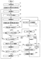
- FIG. 5 is a flow chart showing the main operation flow of the control device 6 that controls the mounting operation of the component P.
- the operation flow of FIG. 5 is performed for each type of substrate K to be produced.
- FIG. 6 is a flowchart showing a detailed operation flow of the retry operation included in FIG.
- step S1 of FIG. 5 the control device 6 performs initial setting. More specifically, the retraction control unit 75 of the control device 6 sets the normal height (HSn, HMn, HLn) when the mounting head (45, 46, 47) moves. Further, the component type registration unit 79 registers in advance the type of the component P to be subjected to the retry operation. For example, when the information indicating whether or not the component P is the target of the retry operation is described in the component data, the component type registration unit 79 can search for the component data and perform registration. Alternatively, the component type registration unit 79 can perform registration based on the input operation of the operator. On the other hand, the coping method setting unit 78 sets in advance a coping method when the retry operation is unsuccessful.
- the save control unit 75 performs an initial determination as to whether or not the save operation is necessary. For example, when the component P mounted on a certain type of substrate K is only large and only the large mounting head 47 having the large suction nozzle 472 is used, the retraction operation is unnecessary. Further, for example, even in the case where only the small component P is mounted using the small mounting head 45 having the small suction nozzle 452, the retraction operation is unnecessary. On the other hand, when the mounting head (45, 46, 47) is automatically replaced in the middle of the mounting operation, there is a possibility of interference due to the drop of the component P, so it is necessary to consider the possibility of the retraction operation. In practice, the sizes of the parts P are various and the judgment logic of the initial judgment is complicated to some extent.
- the evacuation control unit 75 resets the evacuation flag when the evacuation operation is unnecessary, and sets the evacuation flag when considering the evacuation operation.
- the control device 6 controls the substrate transfer device 2 to carry in and position the substrate K.
- the control device 6 controls the component supply device 3 and the component transfer device 4 to start the mounting operation of the component P, that is, the PP cycle.
- the control device 6 causes the component transfer device 4 to perform the suction operation of the component P using the suction nozzles (452, 462, 472).
- the component transfer device 4 rotationally drives the rotary tool 451 clockwise by a predetermined angle A.
- the feeder device 31 feeds the carrier tape 9 by a constant pitch and advances the next cavity portion 93 to the supply position 34.
- step S6 the component detection unit 71 and the holding detection unit 72 operate.
- step S7 the drop determination unit 74 and the retry performing unit 77 check whether the part P is present in the cavity 93 of the supply position 34, that is, the detection result of the part detector 71. Normally, there is a part P at the supply position 34, and execution of the operation flow is advanced to step S8.
- step S8 the drop determination unit 74 and the retry performing unit 77 check the detection result of the holding detection unit 72, that is, whether or not the suction nozzle (452, 462, 472) holds the component P. Usually, the part P is held, and the execution of the operation flow is advanced to step S9.
- step S9 the control device 6 determines whether the suction operation of all the suction nozzles (452, 462, 472) has ended. If not, the control device 6 returns the operation flow to step S5 for the next suction nozzle (452, 462, 472). By repeating the loop from step S5 to step S9, the suction operation of all the suction nozzles (452, 462, 472) is completed. Then, the control device 6 advances the execution of the operation flow to step S10. Note that, depending on the contents of the PP cycle described in the mounting sequence 62, only some of the suction nozzles (452, 462, 472) may be used.
- step S10 the component transfer device 4 moves the mounting head (45, 46, 47) above the component camera 5. Thereby, imaging with the component camera 5 is performed.
- step S11 the component transfer device 4 moves the mounting head (45, 46, 47) to the substrate K and performs the mounting operation of the component P.
- step S12 the control device 6 determines whether all the PP cycles have ended. If not, the control device 6 returns the execution of the operation flow to step S4 for the next PP cycle. The repetition of the loop from step S4 to step S12 completes the entire PP cycle. Then, the control device 6 advances the execution of the operation flow to step S13.
- step S13 the control device 6 carries out the substrate K for which production has been completed. Thereafter, the control device 6 returns the execution of the operation flow to step S3 and starts the mounting operation to the next substrate K.
- the substrate K is mass-produced by repeating the loop from step S3 to step S13. In some cases, unloading of the substrate K for which production has been completed and loading of the next substrate K may be performed simultaneously. This is the explanation of the good progress of the main operation flow.
- step S21 the operation flow branches to step S21.
- the component P is not accommodated in the cavity portion 93 of the carrier tape 9 from the beginning. More specifically, several cavities near the front end and the rear end of the carrier tape 9 are empty cavities where no parts are accommodated from the beginning.
- the empty cavity portion is cut by the operator or stored in advance in the control device 6 so that the suction operation is omitted. Even so, the empty cavity may be determined to be a normal cavity 93 and the suction operation may be performed due to the operator's failure in the cutting operation or an error in the number of empty cavities. In addition, although it is rare, there are cases where parts are not accommodated in the normal cavity 93.
- step S21 the control device 6 rotates the rotary tool 451 counterclockwise by a predetermined angle A in the reverse direction, and returns the execution of the operation flow to step S5.
- step S5 the component transfer device 4 performs the suction operation from the next cavity portion 93 of the carrier tape 9 using the suction nozzles (452, 462, 472) that could not suction the component P again.
- FIG. 7 is a plan view showing a first case in which the small suction nozzle 452 does not hold the component P after the single suction operation is completed from the state of FIG.
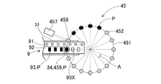
- FIG. 8 is a plan view showing a second case in which the small suction nozzle 452 does not hold the component P after the single suction operation is completed from the state of FIG.
- step S6 the side-view camera 457 captures a situation in which the fifth small suction nozzle 452 does not hold the component P.
- step S31 the branch from step S8 to step S31 is executed.
- the carrier tape 9 is fed by a constant pitch from the situation of FIG.
- the component P remains in the cavity 93X advanced from the supply position 34. Therefore, in the first case, the component P is present in the cavity 93X during the suction operation, and the small suction nozzle 452 can not suction the component P.
- step S31 the retry performing unit 77 of the control device 6 performs the retry operation regardless of the first case and the second case.
- step S51 of FIG. 6 showing details of the retry operation, the retry performing unit 77 sets 1 in the retry counter RC for counting the number of retries.
- the retry performing unit 77 returns the carrier tape 9 by a predetermined pitch, and repositions the cavity portion 93X, which is unclear whether or not the part P remains, at the supply position 34.
- the retry performing unit 77 rotates the rotary tool 451 counterclockwise by a predetermined angle A in the reverse direction to reposition the fifth small suction nozzle 452 at the suction position 459.
- the retry performing unit 77 causes the component transfer device 4 to perform the same suction operation as in step S5. As described above, the rotary drive of the rotary tool 451 and the delivery of the carrier tape 9 are performed in conjunction with the suction operation. In the next step S55, the component detection unit 71, the holding detection unit 72, and the remaining detection unit 73 operate.
- step S56 the drop determination unit 74 and the retry performing unit 77 determine the branch destination of the operation flow based on the detection results of the component detection unit 71 and the remaining detection unit 73.
- step S57 when there is no part P (does not remain), the drop determination unit 74 determines that the “part drop” of the second case occurs. Thereafter, the drop determination unit 74 returns the execution of the control to the main operation flow.
- step S58 when there is a part P (remaining), the retry performing unit 77 determines the branch destination of the operation flow based on the detection result of the holding detection unit 72.
- step S59 when the component P is held by the suction nozzle (452, 462, 472), the retry performing unit 77 determines that “retry is successful” after the first case. Thereafter, the retry performing unit 77 returns the execution of the control to the main operation flow.
- step S60 when the component P is not held by the suction nozzle (452, 462, 472), the retry performing unit 77 determines whether the value of the retry counter RC has reached a predetermined number N of times.
- step S61 when it has not reached, the retry performing unit 77 increases the value of the retry counter RC by 1 and returns the execution of the operation flow to step S52.
- the suction operation of step S54 is executed a predetermined number of times N at maximum.
- step S57 or step S59 may occur.
- the value of the retry counter RC reaches the predetermined number N in step S60, and execution of the operation flow is advanced to step S62.
- step S62 the retry performing unit 77 controls the execution of the end process.
- the end processing does not aim at suction of the part P, but aims at final confirmation of whether or not the part P remains.
- the retry performing unit 77 weakens the negative pressure supplied from the internal pressure control unit 455 to the suction nozzles (452, 462, 472) to perform the suction operation.
- the residual detection unit 73 includes the height measurement sensor, only the descent operation is performed without supplying the negative pressure to the suction nozzles (452, 462, and 472).
- the retry performing unit 77 determines the branch destination of the operation flow based on the detection result of the remaining detection unit 73 at the end processing time. If the part P does not remain, the retry performing unit 77 joins the execution of the operation flow to the “part drop” in step S57. In addition, in step S64 in the case where the part P remains, the retry performing unit 77 determines that “retry is not successful” after the first case. Thereafter, the retry performing unit 77 returns the execution of the control to the main operation flow.
- the “retry failure” occurs when the part P is fixed to the cavity 93X or when the cover tape 92 covering the cavity 93X is not peeled off.
- the result of the retry operation is one of “retry success”, “retry failure”, and “part drop”.
- the retry performing unit 77 determines the branch destination of the operation flow according to the result of the retry operation. In the case of “retry success”, the retry performing unit 77 returns the execution of the operation flow to step S9.
- step S33 in the case of "retry failure” the control device 6 implements the countermeasure method initialized in step S1.
- step S34 in the case of “part drop” the evacuation control unit 75 finally determines whether or not the evacuation operation is necessary, and determines the branch destination of the operation flow. More specifically, when the save flag is reset in step S2, the save control unit 75 can immediately determine that the save operation is unnecessary. In addition, when the retraction flag is set, the retraction control unit 75 compares the size of the part P actually dropped with the type of the mounting head (45, 46, 47) to be used from now, and performs the retraction operation. Determine the necessity.
- the small mounting head 45 when the dropped part P is large, it is necessary to retract the small mounting head 45 and the medium mounting head 46, as is apparent from the description of FIG. In addition, when the dropped part P is medium-sized, the small mounting head 45 needs to retract. When the dropped part P is small, the retraction operation is unnecessary.
- step S35 when the retraction operation is necessary, the retraction control unit 75 retracts the height HSs of the small mounting head 45 and the retraction height of the middle mounting head 46 when the dropped part P is large. Set HMs. Further, the retraction control unit 75 sets only the retraction height HSs of the small-sized mounting head 45 when the dropped part P is medium-sized. When a plurality of parts P are dropped due to the repetition of the operation flow, the evacuation control unit 75 performs setting in consideration of the largest part P among the dropped parts.
- step S36 the save operation notification unit 76 notifies the control execution state of the save operation.
- the save control unit 75 omits step S35 and advances the execution of the operation flow to step S36.
- step S36 in this case, the evacuation operation notification unit 76 notifies that the small part P has been dropped.
- the evacuation control unit 75 merges the execution of the operation flow with step S21.
- the withdrawal heights (HSs, HMs) set in step S35 are continuously used until the production of a predetermined number of substrates K is finished. However, when the operator takes care of the dropped part P and the restart process is subsequently performed, the evacuation heights (HSs, HMs) are normally returned to the heights (HSn, HMn).
- logic is indirectly and logically based on the detection results of the component detection unit 71, the holding detection unit 72, and the remaining detection unit 73 without directly detecting the dropped component P. It can be determined whether or not the part P has dropped. Further, the component detection unit 71, the holding detection unit 72, and the remaining detection unit 73 can be realized by utilizing an existing device configuration, instead of newly providing a sensor or the like. Therefore, the increase in cost required to determine the part drop is suppressed.
- the component mounting machine 1 of the embodiment when suctioning the component P using the suction nozzle (452, 462, 472), it is detected whether or not there is a component at the supply position 34, and It is detected whether 452, 462, 472) holds the part P, and it is determined based on the detection result whether or not to execute the retry operation. Therefore, when there is no part P at the supply position 34 from the beginning, meaningless retry operation can be avoided.
- control device 6 may perform only one control of the control related to the drop determination of the part P and the control related to the retry operation when the part P can not be adsorbed.
- the component supply device 3 is configured by the feeder device 31, and the suction nozzles (452, 462, 472) are used as the component mounting tool, but the invention is not limited thereto. That is, the component supply device 3 may be a device using a tray as a component supply medium or a component supply device of the other type. Further, as the component mounting tool, a clamping type mounting tool for gripping the component P can also be used.
- the configuration may be such that the mounting heads (45 to 47) are manually replaced, or that the mounting heads are not replaced.
- the detection operation (step S55 in FIG. 6) of the component detection unit 71, the holding detection unit 72, and the remaining detection unit 73 during the retry operation is a detection method different from the normal detection operation (step S6 in FIG. 5) You may go there.
- the embodiment is capable of various other modifications and applications.
- Component mounting device 2 Substrate transfer device 3: Component supply device 31: Feeder device 34: Supply position 4: Component transfer device 45: Small mounting head 451: Rotary tool 452: Small suction nozzle 453: Rotational drive unit 454: Lifting drive 456: Negative pressure measuring sensor 457: Side-view camera 458: Detection position 459: Suction position 46: Medium-sized mounting head 462: Medium-sized adsorption nozzle 47: Large-sized installation head 472: Large-sized adsorption nozzle 6: Control device 71: component detection unit 72: retention detection unit 73: residual detection unit 74: drop determination unit 75: evacuation control unit 76: evacuation operation notification unit 77: retry execution unit 78: action method setting unit 79: component type registration unit 9: Carrier tape 93: Yabiti unit 93X: cavity K: the substrate P: Component A: a predetermined angle HSn: Normal Height HMn: Normal Height HLn: Normal Height HSS: retraction height HMS:
Landscapes
- Engineering & Computer Science (AREA)
- Manufacturing & Machinery (AREA)
- Microelectronics & Electronic Packaging (AREA)
- Operations Research (AREA)
- Automation & Control Theory (AREA)
- Supply And Installment Of Electrical Components (AREA)
Abstract
Une machine de montage de composant est pourvue d'un dispositif d'alimentation en composant pour fournir un composant à une position d'alimentation et d'un dispositif de transfert de composant qui utilise un outil de montage de composant pour saisir le composant à partir de la position d'alimentation et monter le composant sur un substrat. La machine de montage de composant comporte en outre : une unité de détection de composant qui détecte si le composant est présent au niveau de la position d'alimentation soit avant que le composant ne soit saisi à l'aide de l'outil de montage de composant soit lors du ramassage du composant ; une unité de détection de maintien qui détecte si l'outil de montage de composant a saisi et tient le composant ; et une unité d'exécution de relance qui utilise le résultat de détection de l'unité de détection de composant et le résultat de détection de l'unité de détection de maintien en tant que base pour déterminer s'il faut exécuter une opération de relance dans laquelle le composant est repris à l'aide de l'outil de montage de composant, puis exécute l'opération de relance sur la base du résultat de détermination.
Priority Applications (7)
| Application Number | Priority Date | Filing Date | Title |
|---|---|---|---|
| EP17925616.9A EP3687269B1 (fr) | 2017-09-22 | 2017-09-22 | Machine de montage de composant et procédé de relance pour saisir des composants |
| JP2019542930A JP6887510B2 (ja) | 2017-09-22 | 2017-09-22 | 部品装着機、および部品採取のリトライ方法 |
| PCT/JP2017/034375 WO2019058529A1 (fr) | 2017-09-22 | 2017-09-22 | Machine de montage de composant et procédé de relance pour saisir des composants |
| US16/646,784 US11317549B2 (en) | 2017-09-22 | 2017-09-22 | Component mounting machine and retry method for picking up components |
| CN201780095051.9A CN111096104B (zh) | 2017-09-22 | 2017-09-22 | 元件安装机及元件拾取的重试方法 |
| JP2021083815A JP7087163B2 (ja) | 2017-09-22 | 2021-05-18 | 部品装着機 |
| JP2022092714A JP7324341B2 (ja) | 2017-09-22 | 2022-06-08 | 部品装着機 |
Applications Claiming Priority (1)
| Application Number | Priority Date | Filing Date | Title |
|---|---|---|---|
| PCT/JP2017/034375 WO2019058529A1 (fr) | 2017-09-22 | 2017-09-22 | Machine de montage de composant et procédé de relance pour saisir des composants |
Publications (1)
| Publication Number | Publication Date |
|---|---|
| WO2019058529A1 true WO2019058529A1 (fr) | 2019-03-28 |
Family
ID=65811526
Family Applications (1)
| Application Number | Title | Priority Date | Filing Date |
|---|---|---|---|
| PCT/JP2017/034375 Ceased WO2019058529A1 (fr) | 2017-09-22 | 2017-09-22 | Machine de montage de composant et procédé de relance pour saisir des composants |
Country Status (5)
| Country | Link |
|---|---|
| US (1) | US11317549B2 (fr) |
| EP (1) | EP3687269B1 (fr) |
| JP (2) | JP6887510B2 (fr) |
| CN (1) | CN111096104B (fr) |
| WO (1) | WO2019058529A1 (fr) |
Cited By (1)
| Publication number | Priority date | Publication date | Assignee | Title |
|---|---|---|---|---|
| EP3986106B1 (fr) * | 2019-06-17 | 2024-09-04 | Fuji Corporation | Dispositif de montage de composant |
Families Citing this family (4)
| Publication number | Priority date | Publication date | Assignee | Title |
|---|---|---|---|---|
| JP6948085B1 (ja) * | 2020-09-09 | 2021-10-13 | 上野精機株式会社 | 電子部品の処理装置 |
| JP7826123B2 (ja) * | 2022-06-07 | 2026-03-09 | ヤマハ発動機株式会社 | 部品実装装置 |
| CN116652873B (zh) * | 2023-08-02 | 2023-10-20 | 河北杰微科技有限公司 | 自动更换吸嘴式封帽机、自动更换吸嘴方法、装置及终端 |
| CN116852066A (zh) * | 2023-08-02 | 2023-10-10 | 河北杰微科技有限公司 | 自动更换吸嘴式封帽机 |
Citations (7)
| Publication number | Priority date | Publication date | Assignee | Title |
|---|---|---|---|---|
| JPH02185387A (ja) * | 1989-01-11 | 1990-07-19 | Aloka Co Ltd | ビーズ移送装置 |
| JPH03256622A (ja) * | 1990-03-08 | 1991-11-15 | Canon Inc | テープ搬送による物品供給装置 |
| JPH053399A (ja) * | 1991-06-26 | 1993-01-08 | Sanyo Electric Co Ltd | 電子部品自動装着装置 |
| JPH1068759A (ja) * | 1996-05-31 | 1998-03-10 | Advantest Corp | 吸着物検知装置、該装置を用いた吸着物検知方法、該装置を用いた位置ずれ検知方法、および該装置を用いた清掃方法 |
| JPH10163686A (ja) | 1996-12-03 | 1998-06-19 | Matsushita Electric Ind Co Ltd | 電子部品装着ヘッド |
| JP2007214476A (ja) * | 2006-02-13 | 2007-08-23 | Matsushita Electric Ind Co Ltd | 電子部品実装方法 |
| JP2008053382A (ja) | 2006-08-23 | 2008-03-06 | Yamaha Motor Co Ltd | 実装機 |
Family Cites Families (19)
| Publication number | Priority date | Publication date | Assignee | Title |
|---|---|---|---|---|
| US5289625A (en) | 1989-04-05 | 1994-03-01 | Canon Kabushiki Kaisha | Method for supplying articles and apparatus therefor |
| US5090113A (en) | 1989-04-05 | 1992-02-25 | Canon Kabushiki Kaisha | Apparatus for supplying articles |
| JP3265143B2 (ja) * | 1994-12-22 | 2002-03-11 | ジューキ株式会社 | 部品搭載方法および装置 |
| EP0895450B1 (fr) * | 1997-07-28 | 2005-11-16 | Matsushita Electric Industrial Co., Ltd. | Alimentateur de composants et dispositif pour le montage |
| JP4494547B2 (ja) | 1999-03-10 | 2010-06-30 | Juki株式会社 | 電子部品検出装置 |
| JP4047021B2 (ja) | 2002-01-30 | 2008-02-13 | 松下電器産業株式会社 | 電子部品実装方法及び電子部品実装装置並びに実装プログラム |
| JP2004351527A (ja) * | 2003-05-27 | 2004-12-16 | Koganei Corp | 吸着検出方法および吸着検出装置 |
| JP4341302B2 (ja) * | 2003-06-09 | 2009-10-07 | パナソニック株式会社 | 電子部品実装装置および電子部品実装方法 |
| JP5410864B2 (ja) * | 2009-07-06 | 2014-02-05 | Juki株式会社 | 電子部品実装装置 |
| CN102118961B (zh) * | 2010-01-06 | 2015-09-16 | Juki株式会社 | 电子部件安装装置 |
| JP5925508B2 (ja) | 2012-02-08 | 2016-05-25 | Juki株式会社 | 電子部品実装装置、電子部品実装システム及び電子部品実装方法 |
| JP6421320B2 (ja) * | 2014-04-24 | 2018-11-14 | パナソニックIpマネジメント株式会社 | 部品実装方法 |
| JP6446670B2 (ja) * | 2015-07-31 | 2019-01-09 | パナソニックIpマネジメント株式会社 | 電子部品装着方法 |
| WO2017022098A1 (fr) * | 2015-08-05 | 2017-02-09 | 富士機械製造株式会社 | Appareil de montage de composants |
| EP3346811B1 (fr) | 2015-08-31 | 2020-07-29 | FUJI Corporation | Dispositif de montage de composants, dispositif d'alimentation, et procédé de détermination de défaut dans un travail d'épissure |
| JP6655355B2 (ja) * | 2015-11-05 | 2020-02-26 | Juki株式会社 | 実装装置及び部品返却方法 |
| US9696661B1 (en) * | 2016-04-28 | 2017-07-04 | Lexmark International, Inc. | Methods for retrying pick in an image-before-pick system |
| JP6796363B2 (ja) * | 2016-10-05 | 2020-12-09 | 株式会社Fuji | 部品実装機 |
| CN110169219B (zh) * | 2017-01-13 | 2020-12-29 | 雅马哈发动机株式会社 | 部件安装装置 |
-
2017
- 2017-09-22 WO PCT/JP2017/034375 patent/WO2019058529A1/fr not_active Ceased
- 2017-09-22 EP EP17925616.9A patent/EP3687269B1/fr active Active
- 2017-09-22 JP JP2019542930A patent/JP6887510B2/ja active Active
- 2017-09-22 US US16/646,784 patent/US11317549B2/en active Active
- 2017-09-22 CN CN201780095051.9A patent/CN111096104B/zh active Active
-
2021
- 2021-05-18 JP JP2021083815A patent/JP7087163B2/ja active Active
Patent Citations (7)
| Publication number | Priority date | Publication date | Assignee | Title |
|---|---|---|---|---|
| JPH02185387A (ja) * | 1989-01-11 | 1990-07-19 | Aloka Co Ltd | ビーズ移送装置 |
| JPH03256622A (ja) * | 1990-03-08 | 1991-11-15 | Canon Inc | テープ搬送による物品供給装置 |
| JPH053399A (ja) * | 1991-06-26 | 1993-01-08 | Sanyo Electric Co Ltd | 電子部品自動装着装置 |
| JPH1068759A (ja) * | 1996-05-31 | 1998-03-10 | Advantest Corp | 吸着物検知装置、該装置を用いた吸着物検知方法、該装置を用いた位置ずれ検知方法、および該装置を用いた清掃方法 |
| JPH10163686A (ja) | 1996-12-03 | 1998-06-19 | Matsushita Electric Ind Co Ltd | 電子部品装着ヘッド |
| JP2007214476A (ja) * | 2006-02-13 | 2007-08-23 | Matsushita Electric Ind Co Ltd | 電子部品実装方法 |
| JP2008053382A (ja) | 2006-08-23 | 2008-03-06 | Yamaha Motor Co Ltd | 実装機 |
Non-Patent Citations (1)
| Title |
|---|
| See also references of EP3687269A4 |
Cited By (1)
| Publication number | Priority date | Publication date | Assignee | Title |
|---|---|---|---|---|
| EP3986106B1 (fr) * | 2019-06-17 | 2024-09-04 | Fuji Corporation | Dispositif de montage de composant |
Also Published As
| Publication number | Publication date |
|---|---|
| EP3687269B1 (fr) | 2024-07-03 |
| EP3687269A4 (fr) | 2020-08-26 |
| EP3687269A1 (fr) | 2020-07-29 |
| JPWO2019058529A1 (ja) | 2020-04-09 |
| US11317549B2 (en) | 2022-04-26 |
| CN111096104A (zh) | 2020-05-01 |
| JP2021119640A (ja) | 2021-08-12 |
| JP7087163B2 (ja) | 2022-06-20 |
| US20200267878A1 (en) | 2020-08-20 |
| JP6887510B2 (ja) | 2021-06-16 |
| CN111096104B (zh) | 2021-06-01 |
Similar Documents
| Publication | Publication Date | Title |
|---|---|---|
| JP7087163B2 (ja) | 部品装着機 | |
| JP5656446B2 (ja) | バックアップピン装置並びにバックアップピン配置方法及び配置装置 | |
| JP6309830B2 (ja) | 部品装着装置 | |
| JP6301635B2 (ja) | 基板検査方法 | |
| US11564341B2 (en) | Reel holding device arranged in component mounting machine and robot system including reel holding device | |
| JP6666915B2 (ja) | 部品実装機 | |
| JP6577965B2 (ja) | 部品供給装置、および保持具決定方法 | |
| JP6838166B2 (ja) | 部品装着機、および部品落下の判定方法 | |
| JPWO2017009931A1 (ja) | ロータリーヘッド型部品実装機 | |
| JP7324341B2 (ja) | 部品装着機 | |
| JP2004071641A (ja) | 部品実装方法及び部品実装装置 | |
| JP2011049279A (ja) | 電子部品装着装置 | |
| JP7759586B2 (ja) | 部品実装装置および部品実装方法 | |
| JP7712480B2 (ja) | 部品突上げ装置及び部品実装装置 | |
| JP3538210B2 (ja) | 電子部品供給装置および空トレイの排出方法 | |
| JP4017900B2 (ja) | 電子部品装着装置 | |
| JP3899950B2 (ja) | 電子部品実装方法 | |
| JP2023007880A (ja) | 部品実装装置および部品実装方法 | |
| JP2025167227A (ja) | 部品供給装置 | |
| JP2026006325A (ja) | 部品装着機 |
Legal Events
| Date | Code | Title | Description |
|---|---|---|---|
| 121 | Ep: the epo has been informed by wipo that ep was designated in this application |
Ref document number: 17925616 Country of ref document: EP Kind code of ref document: A1 |
|
| ENP | Entry into the national phase |
Ref document number: 2019542930 Country of ref document: JP Kind code of ref document: A |
|
| NENP | Non-entry into the national phase |
Ref country code: DE |
|
| ENP | Entry into the national phase |
Ref document number: 2017925616 Country of ref document: EP Effective date: 20200422 |