WO2019058563A1 - Appareil à combustion et procédé de combustion - Google Patents
Appareil à combustion et procédé de combustion Download PDFInfo
- Publication number
- WO2019058563A1 WO2019058563A1 PCT/JP2017/034586 JP2017034586W WO2019058563A1 WO 2019058563 A1 WO2019058563 A1 WO 2019058563A1 JP 2017034586 W JP2017034586 W JP 2017034586W WO 2019058563 A1 WO2019058563 A1 WO 2019058563A1
- Authority
- WO
- WIPO (PCT)
- Prior art keywords
- ammonia
- nozzle
- combustion
- gas
- pulverized coal
- Prior art date
- Legal status (The legal status is an assumption and is not a legal conclusion. Google has not performed a legal analysis and makes no representation as to the accuracy of the status listed.)
- Ceased
Links
Images






Classifications
-
- F—MECHANICAL ENGINEERING; LIGHTING; HEATING; WEAPONS; BLASTING
- F23—COMBUSTION APPARATUS; COMBUSTION PROCESSES
- F23C—METHODS OR APPARATUS FOR COMBUSTION USING FLUID FUEL OR SOLID FUEL SUSPENDED IN A CARRIER GAS OR AIR
- F23C1/00—Combustion apparatus specially adapted for combustion of two or more kinds of fuel simultaneously or alternately, at least one kind of fuel being either a fluid fuel or a solid fuel suspended in a carrier gas or air
- F23C1/12—Combustion apparatus specially adapted for combustion of two or more kinds of fuel simultaneously or alternately, at least one kind of fuel being either a fluid fuel or a solid fuel suspended in a carrier gas or air gaseous and pulverulent fuel
-
- F—MECHANICAL ENGINEERING; LIGHTING; HEATING; WEAPONS; BLASTING
- F23—COMBUSTION APPARATUS; COMBUSTION PROCESSES
- F23C—METHODS OR APPARATUS FOR COMBUSTION USING FLUID FUEL OR SOLID FUEL SUSPENDED IN A CARRIER GAS OR AIR
- F23C5/00—Disposition of burners with respect to the combustion chamber or to one another; Mounting of burners in combustion apparatus
- F23C5/08—Disposition of burners
-
- F—MECHANICAL ENGINEERING; LIGHTING; HEATING; WEAPONS; BLASTING
- F23—COMBUSTION APPARATUS; COMBUSTION PROCESSES
- F23D—BURNERS
- F23D17/00—Burners for combustion simultaneously or alternately of gaseous or liquid or pulverulent fuel
-
- F—MECHANICAL ENGINEERING; LIGHTING; HEATING; WEAPONS; BLASTING
- F23—COMBUSTION APPARATUS; COMBUSTION PROCESSES
- F23K—FEEDING FUEL TO COMBUSTION APPARATUS
- F23K5/00—Feeding or distributing other fuel to combustion apparatus
Definitions
- the present invention relates to a combustion apparatus and a combustion method.
- the present invention relates to a structure and a combustion method of a combustion apparatus suitable for power generation equipment such as a thermal power plant.
- Thermal power plants etc. have installed a boiler as a power generation facility.
- the boiler generates high-temperature and high-pressure steam using the heat produced by burning a fossil fuel such as coal, natural gas, light oil, heavy oil, etc. with a burner.
- burning these fossil fuels generates carbon dioxide, which causes global warming. For this reason, in recent years there has been a move to curb carbon dioxide in the form of carbon credits (emission allowances).
- LNG liquefied natural gas
- LPG liquefied petroleum gas
- LNG is used as fuel for thermal power plants.
- Gas fuels such as LNG need to be liquefied for convenience in transportation.
- ammonia is liquefied at about -33 degrees, so it has the advantage of being easier to liquefy than, for example, LNG requiring about -162 degrees of liquefaction and requiring less expensive equipment.
- a multiple fuel burning combustion apparatus which has a coaxial burner capable of co-firing mixed gas of natural gas and BOG (boil off gas) and pulverized coal inside the boiler (see, for example, Patent Document 2).
- the coaxial burner according to Patent Document 2 comprises an inner pipe for injecting a pulverized coal flame into the interior of a boiler, and surrounding the inner pipe, the flame of a mixed gas of natural gas and BOG being coaxial with the injected direction of the pulverized coal flame. It consists of an outer pipe that jets in the direction.
- ammonia has a low burning rate, specifically, for example, where the burning rate of propane gas is 40 cm / s, the burning rate of ammonia is only 8 cm / s (therefore, when burning ammonia) Flames will be longer).
- the present invention has been made in view of such problems, and an object thereof is to provide a combustion apparatus and a combustion method capable of suppressing the generation of nitrogen oxides and the incomplete combustion of ammonia as much as possible.
- the present inventors are a combustion apparatus for co-firing pulverized coal and ammonia inside a furnace, and a flame in which ammonia is burned is along the tangential direction of a virtual circle whose central axis is the injection direction of the combustion flame of pulverized coal.
- a flame in which ammonia is burned is along the tangential direction of a virtual circle whose central axis is the injection direction of the combustion flame of pulverized coal.
- a combustion apparatus is a combustion apparatus for co-firing pulverized coal and ammonia inside a furnace, and a first nozzle having a first injection port for injecting pulverized coal toward the inside of the furnace; And one or more second nozzles disposed around the first nozzle and having a second injection port for injecting ammonia toward the inside of the furnace, wherein the second injection port of the second nozzle is The combustion flame of ammonia is inclined and opened in the injection direction side of the combustion flame of pulverized coal along the tangential direction of the imaginary circle whose central axis is the injection direction of the combustion flame of pulverized coal.
- an ammonia gas supply pipe for transporting ammonia toward the second nozzle and the first nozzle are disposed at a central portion, and the ammonia gas is distributed from the ammonia gas supply pipe A first gas ring, wherein the second nozzle comprises a plurality of second nozzles disposed around the first nozzle, wherein the second nozzles are configured to receive ammonia gas from the first gas ring It may be supplied.
- an ammonia gas supply pipe for transporting ammonia toward the second nozzle, a gas fuel pipe for transporting gas fuel, and the first nozzle are disposed at a central portion, A second gas ring to which gas fuel is distributed from a gas fuel pipe, a single second nozzle disposed around the first nozzle, and a second gas ring disposed around the first nozzle and directed toward the inside of the furnace And a burner nozzle connecting the second gas ring to the second nozzle and the third nozzle, wherein the burner nozzle connected to the second nozzle is A gas fuel piping shut-off valve capable of opening and closing the flow path of the burner nozzle is provided, and the ammonia gas supply piping can inject ammonia from the second injection port in a state where the gas fuel piping shut-off valve is closed. To, may be directly bonded to the burner nozzle connected to said second nozzle.
- the combustion method according to the present invention is a combustion method used in the combustion apparatus according to any one of (1) to (3), in which pulverized coal and ammonia are co-fired in the furnace, and the first nozzle
- the mixed combustion rate of ammonia, which is injected so as to be combustible from the second nozzle, is 0.8% or more with respect to pulverized coal which is injected so as to be combustible from the above.
- the combustion apparatus is a combustion apparatus in which pulverized coal and ammonia are co-fired inside a furnace, and a flame in which ammonia is burned is a virtual circle whose central axis is the injection direction of the combustion flame in which pulverized coal is burned. Since the injection is performed along the tangential direction and inclined to the injection direction side of the combustion flame of pulverized coal, the combustion time of ammonia can be secured, and the incomplete combustion of ammonia can be suppressed as much as possible.
- the mixed combustion ratio of ammonia injected from the second nozzle to the combustible gas from the second nozzle is 0.8% or more with respect to pulverized coal injected from the first nozzle to the combustible gas, The occurrence of objects can be suppressed as much as possible.
- FIG. 14 (a) is a graph which shows the time change of coal usage-amount per unit time
- Fig. 14 (b) is a table showing the time change of the amount of coal used per unit time
- Fig. 14 (b) is a table showing the time change of the amount of coal used per unit time
- FIG. 14 (c) is a table showing the time change of the average output of the power generation facility. It is a figure which shows the measurement point which measured the ammonia concentration of the exit of a combustion apparatus using the combustion apparatus by 3rd Embodiment. It is a figure which shows the time change of the NOx value of the exit of a combustion apparatus using the combustion apparatus by 3rd Embodiment, FIG. 16 (a) is a graph which shows the time change of a NOx value, FIG.16 (b) is.
- FIG. 16C is a table showing the time change of NOx value, and FIG.
- FIG.17 (a) is the ammonia injection amount per unit time, and CO2 content
- FIG.17 (b) is a table which shows the time change of the amount of ammonia injection per unit time, and CO2 content.
- FIG. 1 is a functional block diagram showing a configuration according to an embodiment of a thermal power plant equipped with a combustion apparatus according to the present invention.
- the thermal power generation facility 1 of one embodiment is a system capable of burning ammonia gas, but it is also possible to burn other than ammonia gas such as pulverized coal, oil, natural gas, or BOG.
- the thermal power generation facility 1 includes an ammonia gas supply facility 2 and an ammonia gas fuel piping facility 3. Further, the thermal power generation facility 1 includes a boiler (furnace) 6, a denitration facility 90, and a gas fuel supply unit 70. The gas fuel supply unit 70 can supply gas fuel other than ammonia gas to the boiler 6 via the gas fuel pipe 170. Furthermore, the thermal power generation facility 1 includes a control unit 7. The control unit 7 controls the whole of these devices.
- the ammonia gas supply facility 2 includes a storage tank 10 and a vaporizer 20. Further, the ammonia gas supply facility 2 includes an accumulator 30 and an ammonia gas absorbing unit 80. In addition, the ammonia gas absorption part 80 is a water storage tank which stored water as a reality. The ammonia gas absorbing unit 80 can absorb the ammonia gas discharged from the blow valve 81 provided in the ammonia gas supply facility 2 into water.
- the storage tank 10 stores pressurized and liquefied liquid ammonia.
- the storage tank 10 is connected to the vaporizer 20 through a pipe 110.
- the pipe 110 bifurcates in two directions on the way to the vaporizer 20.
- a vaporizer start valve 11 and a vaporizer pressure control valve 12 for controlling the pressure in the vaporizer 20 are sequentially disposed from the upstream side.
- a vaporizer bypass valve 13 is disposed in the other branched pipe 110b.
- the vaporizer 20 heats and vaporizes liquid ammonia supplied from the storage tank 10.
- the liquid ammonia inside the vaporizer 20 can be heated and vaporized through the inside of the coiled pipe immersed in the hot water to generate ammonia gas.
- the downstream side of the vaporizer 20 is connected to the accumulator 30 via a pipe 120.
- the pipe 120 bifurcates in two directions on the way to the accumulator 30.
- An accumulator start valve 21 and an accumulator pressure control valve 22 for controlling the pressure in the accumulator 30 are sequentially arranged from the upstream side in one branched pipe 120a.
- An accumulator bypass valve 23 is disposed in the other branched pipe 120b.
- the accumulator 30 is a device that accumulates ammonia gas and stabilizes pressure.
- a pipe 130 extends from the downstream side of the accumulator 30.
- the pipe 130 branches in two directions.
- One branched pipe 132 is connected to the header 40.
- the other branched pipe 131 is connected to the ammonia gas fuel pipe arrangement 3.
- the header 40 has a pipe 140 connected downstream thereof.
- the pipe 140 is branched into a plurality of NOx removal pipes 141, 142, and 143.
- These denitration pipes 141, 142 and 143 are connected to the denitration equipment 90 via denitration shutoff valves 41, 42 and 43.
- the denitration equipment 90 is composed of three denitration devices 91, 92, 93.
- the NOx removal pipes 141, 142 and 143 are connected to the three NOx removal devices 91, 92 and 93, respectively.
- the exhaust gas produced by combustion from the combustion device 6 is fed into the NOx removal piping 141, 142, 143, and ammonia gas introduced from the piping in which the NOx removal shutoff valve 41, 42, 43 of 141, 142, 143 is opened.
- nitrogen oxides in exhaust gas can be converted to harmless nitrogen gas and water.
- the configuration of the ammonia gas fuel piping installation 3 will be described.
- the pipe 131 branched from the pipe 130 extending from the accumulator 30 is connected to the ammonia gas fuel pipe arrangement 3.
- the shutoff valve 31 is provided on the upstream side of the pipe 131.
- the purge pipe 133 is connected to the downstream side of the shutoff valve 31 via the purge valve 36.
- a purge gas supply unit 37 is connected to the end of the purge pipe 133.
- the purge gas supply unit 37 can flow a purge gas such as nitrogen gas into the ammonia gas fuel piping installation 3.
- the downstream side of the connecting portion of the pipe 131 to which the purge pipe 133 is connected is branched in two directions.
- a pressure control valve 32 is disposed in one branched pipe 131a.
- the shutoff valve 33 is disposed in the other branched pipe 131 b.
- the pipe 131 a and the pipe 131 b rejoin on the downstream side.
- the joined pipe 131 is connected to the flow meter 50 via the shutoff valve 34.
- the flow meter 50 measures the flow rate of gas flowing through the pipe 131.
- a pipe 150 extends from the downstream side of the flow meter 50.
- the piping 150 branches in two directions along the way.
- a flow control valve 51 is disposed in one of the branched pipes 150a.
- a shutoff valve 52 is disposed in the other branched pipe 150b. The pipe 150 a and the pipe 150 b rejoin on the downstream side.
- the downstream side of the joined pipe 150 branches in two directions at the second connection portion 56.
- One branched pipe is an ammonia gas outflow pipe 151 a, and is connected to the ammonia gas absorbing unit 80 of the ammonia gas supply facility 2 via an ammonia outflow shutoff valve 55.
- the ammonia gas absorbing unit 80 is a water storage tank, and can dissolve ammonia gas in water.
- a burner valve 53 is disposed in the other branched ammonia gas supply pipe 151 b.
- a cooling pipe 160 into which cooling air is introduced is connected via a cooling air valve 61.
- the ammonia gas outflow pipe 151 a may be branched downstream of the burner valve 53.
- the downstream side of the ammonia gas supply pipe 151 b is connected to the first connection portion 72 of the gas fuel pipe 170 extending from the gas fuel supply unit 70 to the burner 62 A of the boiler 6 via the shutoff valve 54. ing.
- the gas fuel supply unit 70 stores LNG (liquefied natural gas).
- LNG liquefied natural gas
- LNG is vaporized due to natural heat input from the outside, etc., and BOG off gas is generated.
- the gas fuel pipe 170 is a pipe for transporting the BOG as a fuel to a burner described later.
- the gas fuel pipe 170 is connected to the burner of the combustion device 6 on the downstream side of the first connection portion 72.
- a gas fuel pipe shutoff valve 71 is disposed on the upstream side of the first connection portion 72 in the gas fuel pipe 170.
- BOG can be supplied to the burner 62A by closing the shutoff valve 54 and opening the gas fuel pipe shutoff valve 71.
- ammonia can be supplied to the burner.
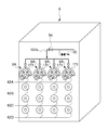
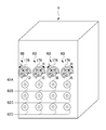
- the boiler 6 has a plurality of burners arranged in rows and columns.
- the four stage burners 62A, 62B, 62C, 62D are arranged in the height direction. Also, these burners are arranged in four rows in the horizontal direction.
- coal dust coal
- gas fuel or ammonia can be supplied to the top four burners 62A.
- the combustion apparatus according to the present invention is, as a substance, four burners 62A disposed at the top of the boiler 6. And embodiment is different by supplying ammonia to all or one part of four top burners 62A.
- the combustion apparatus according to the first embodiment is a combustion apparatus 6A
- the combustion apparatus according to the second embodiment is a combustion apparatus 6B
- the combustion apparatus according to the third embodiment is a combustion apparatus 6C. explain.
- the combustion apparatus according to the first embodiment does not include the gas fuel supply unit 70 disclosed in FIG. 1.
- FIG. 2 is a perspective view showing the configuration of the combustion apparatus according to the first embodiment of the present invention.
- FIG. 3 is an enlarged front view of a gas ring provided in the combustion apparatus according to the first embodiment.
- FIG. 4 is an enlarged vertical sectional view of a first nozzle provided in the combustion apparatus according to the first embodiment.
- FIG. 5 is an enlarged vertical cross-sectional view of the tip of the first nozzle provided in the combustion apparatus according to the first embodiment.
- 6 is a view on arrow X in FIG.
- FIG. 7 is a layout view of the plurality of second nozzles provided in the combustion apparatus according to the first embodiment, and is a state diagram when viewing the plurality of second nozzles from the furnace side.
- the combustion apparatus 6A includes an arc-shaped first gas ring 171.
- the first gas ring 171 forms a cylindrical pipe member in an arc shape.
- the first gas ring 171 is partially interrupted.
- the first gas ring 171 closes its both ends.
- the first gas ring 171 is supplied with ammonia gas from an ammonia gas supply pipe 151 b.
- the first gas ring 171 has a long first nozzle 175 disposed at the center.
- the first nozzle 175 Around the first nozzle 175, five long second nozzles 173A, 173B, 173C, 173D and 173E are disposed. Since these second nozzles 173A, 173B, 173C, 173D, and 173E are the same, the second nozzle 173B may be described as a representative.
- the first gas ring 171 projects five burner nozzles 172A, 172B, 172C, 172D and 172E toward the center. These burner nozzles 172A, 172B, 172C, 172D, 172E are connected to the second nozzles 173A, 173B, 173C, 173D, 173E.
- ammonia gas when ammonia gas is supplied to the first gas ring 171, ammonia gas is supplied from the second injection port 173h provided at the tip of these second nozzles 173A, 173B, 173C, 173D, 173E. Can be injected (see FIG. 5 or FIG. 6).
- the combustion apparatus 6A supplies ammonia gas to the four first gas rings 171 disposed at the uppermost stage of the boiler 6, and the five second nozzles connected to the first gas rings 171 Ammonia gas can be injected from 173A, 173B, 173C, 173D and 173E. That is, ammonia gas can be injected from the one second nozzle 173B toward the inside of the furnace.
- the burner nozzle 172A, 172B, 172C, 172D, 172E is provided with a gas fuel pipe shutoff valve 71B.
- a gas fuel pipe shutoff valve 71B By opening the gas fuel pipe cutoff valve 71B, ammonia gas can be injected from the second injection port 173h (see FIG. 5 or FIG. 6).
- By closing the gas fuel pipe shutoff valve 71B it is possible to stop the injection of the ammonia gas from the second injection port 173h.
- the first nozzle 175 opens the first injection port 175 h at its tip.
- the first injection port 175 h can inject pulverized coal horizontally toward the inside of the furnace of the combustion device 6 ⁇ / b> A.
- the first nozzle 175 holds the heavy fuel oil burner 174 inside.
- the heavy fuel oil burner 174 can inject misty heavy oil or diesel toward the inside of the furnace of the combustion apparatus 6A.
- the pulverized coal injected from the first nozzle 175 can be burned by igniting this heavy oil or light oil. Further, the ammonia gas injected from the second injection port 173 h can be mixedly burned.
- the second nozzle 173 ⁇ / b> B is disposed such that its axial direction is substantially parallel to the first nozzle 175.
- the second injection port 173 h of the second nozzle 173 B has a smaller inner diameter than the inner diameter of the second nozzle 173 B.
- the second injection port 173 h is in the flow direction C0 of ammonia gas flowing inside the second nozzle 173 B (that is, in the injection direction of pulverized coal injected from the first nozzle 175).
- the injection direction C of the ammonia gas is bent and injected with respect to the substantially parallel direction).
- the second injection port 173 h opens along a tangential direction B of a virtual circle whose central axis is the injection direction of the combustion flame of pulverized coal.
- the ammonia gas injected from the second injection port 173 h is injected along the tangential direction B of the imaginary circle whose central axis is the injection direction of the combustion flame of pulverized coal.
- “along the tangential direction B” means that the injection direction C (the angle ⁇ shown in FIG. 6) in which the ammonia gas is actually injected to the tangential direction B is about ⁇ 30 degrees
- Represents a state that falls within the range of Arrows A shown in FIGS. 6 and 7 indicate the direction from the second injection port 173 h toward the center of the first injection port 175 h.
- the injection direction C of the ammonia gas is inclined with respect to the tangential direction B at a predetermined angle ⁇ toward the injection direction side of the combustion flame of pulverized coal.
- the ammonia gas injection direction C follows the tangential direction B and at a predetermined angle ⁇ on the front side of the paper surface in FIG. It is inclined. It is preferable to have an inclination angle ⁇ to the injection direction side of the combustion flame of pulverized coal in the injection direction C of ammonia gas.
- the combustion apparatus 6A burns the pulverized coal so that the flame in which the ammonia is burned is along the tangential direction B of the imaginary circle whose central axis is the injection direction of the combustion flame in which the pulverized coal is burned. Since the fuel is inclined and injected toward the flame injection direction, the combustion time of ammonia can be secured, and the incomplete combustion of ammonia can be suppressed as much as possible.
- the combustion apparatus 6A is a combustion apparatus 6A that co-fires pulverized coal and ammonia in the furnace, and the flame in which the ammonia is burned is a combustion flame of pulverized coal.
- Ammonia is injected from the second nozzles 173A, 173B, 173C, 173D, and 173E along the tangential direction of the imaginary circle whose central axis is the injection direction, so incomplete combustion of ammonia can be minimized by the combustion flame of pulverized coal. , Can be suppressed.
- ammonia is injected from the second nozzles 173A, 173B, 173C, 173D and 173E along the tangential direction of the combustion flame of pulverized coal, so a swirling flow is made around the combustion flame of pulverized coal. It is also possible to form.
- the flame in which ammonia is burned is made to be along the tangential direction of a virtual circle whose center axis is the injection direction of the combustion flame of pulverized coal around the flame in which pulverized coal is burned.
- the ammonia is injected by being inclined to the injection direction side of the combustion flame of the pulverized coal, the incomplete combustion of the ammonia can be suppressed as much as possible by securing the combustion time of the ammonia.
- 6 A of combustion apparatuses by 1st Embodiment can suppress generation
- FIG. 8 is a perspective view showing the configuration of a combustion apparatus according to a second embodiment of the present invention.
- FIG. 9 is an enlarged front view of a gas ring provided in the combustion apparatus according to the second embodiment.
- the combustion device 6 ⁇ / b> B includes an arc-shaped second gas ring 178.
- the second gas ring 178 has a long first nozzle 175 disposed at the center.
- a long second nozzle 173B is disposed around the first nozzle 175.
- long third nozzles 178A, 178C, 178D, 178E are disposed around the first nozzle 175.
- the second gas ring 178 projects five burner nozzles 172A, 172B, 172C, 172D and 172E toward the center.
- the burner nozzle 172B is connected to the second nozzle 173B.
- the burner nozzles 172A, 172C, 172D and 172E are connected to the third nozzles 178A, 178C, 178D and 178E.
- the ammonia gas is supplied to the burner nozzle 172B from the ammonia gas supply pipe 151b.
- the ammonia gas can be injected from the second injection port 173h provided at the tip of the second nozzle 173B (see FIG. 5 or FIG. 6).
- pulverized coal and ammonia can be co-fired inside the furnace.
- the combustion apparatus 6B supplies ammonia gas to the burner nozzles 172B of the four second gas rings 178 disposed at the uppermost stage of the boiler 6, and one second nozzle connected to the burner nozzle 172B.
- Ammonia gas can be injected from 173B. That is, ammonia gas can be injected from the four second nozzles 173B toward the inside of the furnace.
- a gas fuel pipe shutoff valve 71B is provided on the upstream side of the connecting portion of the burner nozzle 172B with the ammonia gas supply pipe 151b.
- the second gas ring 178 connects the gas fuel pipe 170 (see FIG. 1).
- the gas fuel can be supplied to the third nozzles 178A, 178C, 178D, 178E via the burner nozzles 172A, 172C, 172D, 172E.
- gas fuel can be injected toward the inside of a furnace from the tip part of 3rd nozzle 178A, 178C, 178D, and 178E, and gas fuel can be burned.
- the gaseous fuel can also be injected from the second nozzle 173B via the burner nozzle 172B.
- the combustion apparatus 6B according to the second embodiment can also burn gaseous fuel with the topmost burner 62A.
- the first gas ring 171 and the second gas ring 178 are structurally the same, but are distinguished by changing the sign because the flowing combustion is different.
- the second nozzle 173B and the third nozzle 178A, 178C, 178D, 178E are structurally the same, they are distinguished by changing the sign because the flowing combustion is different.
- the combustion apparatus 6A according to the first embodiment injects ammonia gas from all the first nozzles 173A, 173B, 173C, 173D and 173E, while according to the second embodiment.
- the difference is that the combustion device 6B can inject ammonia gas from the specific second nozzle 173B.
- the combustion flame of ammonia injected from the second injection port 173 h follows the tangential direction of the imaginary circle whose central axis is the injection direction of the combustion flame of pulverized coal, and By opening the periphery of the injection hole 175 h at a predetermined inclination angle ⁇ , the combustion time of ammonia can be secured, and the ammonia can be completely burned.
- the second gas ring 178 may be connected to an air supply line (not shown) instead of the gas fuel pipe 170.
- air is injected from the second nozzles 173A, 173B, 173C, 173D and 173E along the tangential direction of the combustion flame of pulverized coal, so the periphery of the combustion flame of pulverized coal It is also possible to form a swirling flow on the
- the ammonia gas injected from the burner nozzle 173B of the second gas ring 178 disposed at the right end (A) of the uppermost stage of the boiler 6 and the third from the right (C) swirls in the clockwise direction R
- the ammonia gas injected from the burner nozzle 178C of the second gas ring 178 disposed at the left end (D) of the uppermost stage of the boiler 6 and the third from the left (B) can swirl in the counterclockwise direction L. Also, this makes it possible to burn the ammonia gas uniformly without deviation.
- the flame in which the ammonia is burned is in the tangential direction B of the imaginary circle whose central axis is the injection direction of the combustion flame in which the pulverized coal is burned. Since the fuel is injected along the injection direction side of the combustion flame of pulverized coal at a predetermined angle ⁇ , the combustion time of the ammonia can be secured, and the incomplete combustion of the ammonia can be suppressed as much as possible.
- Third Embodiment Composition of combustion device
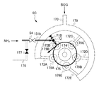
- FIG. 10 is a perspective view showing the configuration of a combustion apparatus according to a third embodiment of the present invention.
- FIG. 11 is an enlarged front view of a third gas ring provided in the combustion apparatus according to the third embodiment.
- FIG. 12 is a layout view of the second nozzle and the fourth nozzle provided in the combustion apparatus according to the third embodiment, in which the second nozzle and the fourth nozzle are viewed from the furnace side.
- the combustion apparatus 6C is disposed on the rightmost side of the topmost burner 62A. Then, in the left three rows of the uppermost stage burner 62A, a combustion device 6D to which ammonia gas is not supplied is disposed. While the combustion device 6C injects ammonia, the combustion device 6D can inject only gas fuel.
- the combustion devices 6C and 6D include a third gas ring 179. Referring to FIG. 11, the third gas ring 179 has a long first nozzle 175 disposed at the center.
- the combustion device 6 ⁇ / b> C arranges a long second nozzle 173 ⁇ / b> B around the first nozzle 175.
- the combustion device 6C has long fourth nozzles 179A, 179C, 179D, 179E arranged around the first nozzle 175.
- the combustion device 6D has long fourth nozzles 179A, 179B, 179C, 179D, 179E arranged around the first nozzle 175.
- the third gas ring 179 of the combustion device 6D protrudes five burner nozzles 172A, 172B, 172C, 172D and 172E toward the central portion.
- the burner nozzle 172B is connected to the second nozzle 173B.
- the burner nozzles 172A, 172C, 172D, 172E are connected to the fourth nozzles 179A, 179C, 179D, 179E.
- the ammonia gas is supplied to the second nozzle 173B from the ammonia gas supply pipe 151b.
- the ammonia gas can be injected from the second injection port 173h provided at the tip of the second nozzle 173B (see FIG. 5 or FIG. 6).
- pulverized coal and ammonia can be co-fired inside the furnace.
- the combustion apparatus 6C supplies ammonia gas to the burner nozzle 172B of one third gas ring 179 disposed at the right end of the uppermost stage of the boiler 6, and connects one burner nozzle 172B to the burner nozzle 172B.
- the ammonia gas can be injected from the two nozzles 173B.
- the third gas ring 179 of the combustion apparatus 6C connects the gas fuel pipe 170 (see FIG. 1).
- the gas fuel can be supplied to the fourth nozzles 179A, 179C, 179D, 179E via the burner nozzles 172A, 172C, 172D, 172E.
- gas fuel can be injected toward the inside of a furnace from the tip part of the 4th nozzle 179A, 179C, 179D, and 179E, and gas fuel can be burned.
- a gas fuel pipe shutoff valve 71B is provided on the upstream side of the connecting portion of the burner nozzle 172B with the ammonia gas supply pipe 151b.
- gaseous fuel can also be injected from the second nozzle 173B via the burner nozzle 172B.
- the combustion apparatus 6C according to the third embodiment can also burn gaseous fuel.
- the first gas ring 171 and the third gas ring 179 are structurally the same, but are distinguished by changing the sign because the flowing combustion is different.
- the second nozzle 173B and the fourth nozzle 179A, 179B, 179C, 179D, 179E are structurally the same, they are distinguished by changing the sign because the circulating combustion is different.
- the ammonia gas supply pipe 151 b is provided with a shutoff valve 54.
- a return pipe 176 branches off upstream of the shutoff valve 54.
- a shutoff valve 177 is provided in the return pipe 176.
- the return pipe 176 is a pipe used when the ammonia gas is not supplied to the burner nozzle 172B from the ammonia gas supply pipe 151b.
- the shutoff valve 54 is closed and the shutoff valve 177 is opened.
- the combustion apparatus 6B by 2nd Embodiment injects ammonia gas from the 2nd nozzle 173B of all the 2nd gas rings 178, but 3rd implementation
- the combustion apparatus 6C according to the embodiment has a difference that the ammonia gas is injected from the second nozzle 173B of the specific third gas ring 179.
- the combustion apparatus 6B and the combustion apparatus 6C are the same, and the second embodiment arranges the four combustion apparatuses 6B, while the third embodiment performs the combustion. There is a difference that only one device 6B is arranged.
- the combustion device 6C is arranged such that the flame in which ammonia is burned is along the tangential direction B of a virtual circle whose central axis is the injection direction of the combustion flame in which pulverized coal is burned and Since the injection is performed with the predetermined angle ⁇ inclined to the injection direction side of the combustion flame of pulverized coal, the combustion time of ammonia can be secured, and the incomplete combustion of ammonia can be suppressed as much as possible.
- the third gas ring 179 may be connected to an air supply line (not shown) instead of the gas fuel pipe 170.
- air is injected from the fourth nozzles 179A, 179C, 179D, 179E along the tangential direction of the combustion flame of pulverized coal, so the swirling flow around the combustion flame of pulverized coal It is also possible to form
- a combustion apparatus 6C is a combustion apparatus 6C for co-firing pulverized coal and ammonia inside a furnace, and a flame in which ammonia is burned causes the pulverized coal to be burned.
- the ammonia is injected at a predetermined angle ⁇ to the injection direction side of the combustion flame of the pulverized coal so that the periphery of the flame is along the tangential direction of the imaginary circle whose central axis is the injection direction of the combustion flame of the pulverized coal Therefore, the incomplete combustion of ammonia can be suppressed as much as possible by securing the combustion time of ammonia.
- the shutoff valve 54 provided in the ammonia gas supply pipe 151 b is opened, and ammonia is closed by closing the gas fuel pipe shutoff valve 71 B provided in the burner nozzle 172 B and the shutoff valve 177 provided in the return pipe 176.
- the gas is supplied to the second nozzle 173B via the ammonia gas supply pipe 151b ⁇ the first connection portion 72 ⁇ the burner nozzle 172B.
- the cross section perpendicular to the length direction of the pulverized coal flame injected from the first nozzle 175 is approximated to a circle, as shown by the arrow in FIG. 12, the second injection port 173h of the second nozzle 173B is , Ammonia is injected in the tangential direction of this circle.
- the ammonia is placed along the tangential direction of the imaginary circle centered on the injection direction of the combustion flame of the pulverized coal around the periphery of the pulverized coal flame and on the injection direction side of the combustion flame of the pulverized coal Since ammonia is injected at a predetermined angle ⁇ , the combustion distance of ammonia is increased, whereby the combustion time of ammonia can be secured and the ammonia can be completely burned.
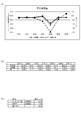
- FIG. 13 is a graph showing the time-dependent change of the ammonia combustion amount used when the combustion test was performed using the combustion apparatus according to the third embodiment.
- FIG. 14 is a diagram showing the time change of the amount of used coal when the combustion test was performed using the combustion apparatus according to the third embodiment, and FIG. 14 (a) is a timing of the used amount of coal per unit time The graph which shows change, FIG.14 (b) is a table
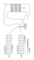
- FIG. 15 is a view showing measurement points at which the ammonia concentration at the outlet of the combustion apparatus is measured using the combustion apparatus according to the third embodiment.
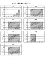
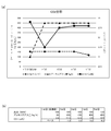
- FIG. 16 is a diagram showing the time change of the NOx value at the outlet of the combustion device using the combustion device according to the third embodiment, and FIG. 16 (a) is a graph showing the time change of the NOx value; b) is a table showing the time change of the NOx value, and FIG. 16 (c) is a table showing the time change of the average output of the power generation facility.
- FIG. 17 is a diagram showing the time change of the CO 2 content in the exhaust gas discharged from the combustion apparatus using the combustion apparatus according to the third embodiment
- FIG. 17 (a) is an ammonia injection per unit time
- FIG.17 (b) is a table which shows the time change of the amount of ammonia injection per unit time, and CO2 content.
- the test period is 7 days, from 13 o'clock to 17 o'clock on the first day, 10 o'clock to 17 o'clock on the second day to the 6th day, and 10 o'clock to 13 o'clock on the 7th day
- a maximum of 450 kg / h of ammonia (note that this is the maximum flow rate of the vaporizer 20 and corresponds to 400 kg of coal) was used.
- the mixed combustion rate of ammonia was about 0.6% (equivalent to 1 MW), but only on the fifth day, the boiler was operated at a load of 120 MW The mixed combustion rate of ammonia was about 0.8%.
- ammonia was burned in the range where there is no excess of exhaust gas.
- liquid ammonia used for combustion has a purity of 99.98%, water content of 0.016%, and an oil content of less than 1.0 ppm, and coal species co-fired with ammonia is 60% for mount oren, and Bocabri premium Is 40%.
- the temperature of metal parts such as piping provided in the boiler 6, that is, the boiler metal temperature was measured at the time of coal-only combustion and at the time of mixed combustion of ammonia and coal.
- the boiler metal temperature at the primary superheater outlet is 400 to 450 ° C.
- the boiler metal temperature at the reheater outlet is 500 to 550 ° C.
- the boiler metal temperature at the secondary superheater inlet is 400 to 450 ° C
- the boiler metal temperature at the middle of the secondary superheater is 450 to 500 ° C
- the boiler metal temperature at the secondary superheater outlet is 500 to 600 ° C.
- the boiler metal temperature at the primary superheater outlet is 400 to 450 ° C
- the boiler metal temperature at the reheater outlet is 500 to 600 ° C
- the boiler metal at the secondary superheater inlet The temperature is 400 to 450 ° C
- the boiler metal temperature in the middle of the secondary superheater is 450 to 550 ° C
- the boiler metal temperature at the outlet of the secondary superheater is 500 to 600 ° C. And there was almost no change.
- FIG. 14 shows the amount of coal used per hour before and after mixed combustion, and the difference between the amounts of coal used.
- the table in FIG. 14 (b) shows the numerical values used in the graph of (a) in the form of a table, and the table in FIG. 14 (c) Indicates the average value of
- the reduction in the amount of used coal after mixed firing compared with that before mixed firing was 0.50 T / h on average for 7 days. That is, 450 kg / h of the amount of ammonia combustion became almost the same as 500 kg / h (anhydrous) of the amount of reduction of coal. Also, comparing the 1st to 7th days, the amount of reduction of coal on the 5th day became the maximum value of 1.96T / h.
- the coal type of coal used for the combustion is 60% of Mount Oen and 40% of Boca-Bri Premium.
- FIG. 16 shows NOx values at the boiler outlet before and after mixed combustion.
- the table of FIG. 16 (b) shows the numerical values used in the graph of FIG. 16 (a) in the form of a table
- the table of FIG. 16 (c) shows the power plant output, mixed combustion rate
- FIG. 16 (c) The average value of the day difference shown in the leftmost column of Further, the value before mixed combustion is a value 30 minutes before the injection of ammonia, and the value after mixed combustion is an average value of data of 4 to 5 points taken every 30 minutes after the injection of ammonia.
- the mixed combustion rate of ammonia is about 0.6% to about 0.8 as compared to other days. It was confirmed that the NOx value at the boiler outlet after co-firing decreased significantly as compared to before co-firing, contrary to the increase to%.
- the mixed burning rate of ammonia was about 0.6%, compared to the mixed burning before mixed burning. While the increase in NOx value after that was not stable, the average value showed a positive value of 0.17 ppm, while the mixed combustion rate of ammonia was about 0.8% on the 5th, before mixed combustion It was confirmed that the amount of increase in NOx value after mixed combustion compared to the above became a negative value of -13.75 ppm.
- the ammonia co-firing rate is desirably 0.8% or more, and it has been suggested that the NOx value can be reduced as the ammonia supply amount is increased. This is, 4NO + 4 NH 3 + O 2 ⁇ 4 N 2 + 6 H 2 O It is presumed that the noncatalytic denitrification reaction has progressed as shown in the chemical reaction formula.
- ammonia is injected in the tangential direction of the pulverized coal flame so that the ammonia draws a spiral locus around the pulverized coal flame, and the combustion time of the ammonia is secured by taking a long combustion distance of the ammonia. It is estimated that
- FIG. 17 shows the output of the boiler, the amount of injected ammonia, and the amount of CO 2 in the exhaust gas from the boiler.
- the table of (b) shows the numerical values used in the graph of (a) in the form of a table.
- the mixed combustion rate of ammonia is 0.6% to 0.8%, so the CO 2 amount is the product of those numerical values, 0. It was predicted to decrease by as little as 1%, but in practice it decreased by 0.2 to 1.3%.
- the annual carbon dioxide reduction amount when the mixed combustion rate is about 0.6% is about 3.99 (thousand t-CO 2 / year), and the annual carbon dioxide reduction when the mixed combustion rate is about 0.8% The amount was about 4.12 (thousand t-CO 2 / year).
- the carbon dioxide emission factor was calculated using the emission factor by electric power company in FY2015 (China Electric Power: 0.0007t-CO2 / kWh) and the facility operation rate as 70%. It is considered that carbon dioxide emissions can be reduced according to the rate of mixed combustion, since all mixed ammonia could be burned in the boiler.
- the combustion apparatus according to the present invention is a combustion apparatus for co-firing pulverized coal and ammonia inside a furnace, and a flame in which ammonia is burned burns pulverized coal around a flame in which pulverized coal is burned.
- Ammonia is injected by tilting to the injection direction side of the combustion flame of pulverized coal so as to be along the tangential direction of a virtual circle whose central axis is the injection direction, so by securing the combustion time of ammonia, incompleteness of ammonia Combustion can be suppressed as much as possible.
- the ammonia is injected in the tangential direction around the pulverized coal flame, and the combustion distance of the ammonia is increased, whereby the combustion time of the ammonia is secured and the ammonia is completely burned.
- the mixed combustion ratio of ammonia injected from the second nozzle to the combustible from the second nozzle is 0.8% or more with respect to pulverized coal injected to the combustion from the first nozzle. And the generation of nitrogen oxides can be suppressed as much as possible.
- the ammonia used for the combustion simultaneously has an effect of denitrifying NOx in the exhaust gas generated by the combustion, so that the ammonia can be effectively used.
Landscapes
- Engineering & Computer Science (AREA)
- Chemical & Material Sciences (AREA)
- Combustion & Propulsion (AREA)
- Mechanical Engineering (AREA)
- General Engineering & Computer Science (AREA)
- Combustion Of Fluid Fuel (AREA)
Abstract
L'invention concerne un appareil à combustion et un procédé de combustion permettant de supprimer, autant que possible, la production d'oxydes d'azote et la combustion incomplète de l'ammoniac. L'appareil de combustion (6A) peut brûler simultanément du charbon pulvérisé et de l'ammoniac à l'intérieur d'un four. L'appareil de combustion (6A) est muni d'une première buse (175) et d'au moins une seconde buse (173B). La première buse (175) comporte un premier orifice à jet (175h) à travers lequel du charbon pulvérisé est injecté vers l'intérieur du four. Les secondes buses (173B) sont disposées autour de la première buse (175). Chaque seconde buse (173B) comporte un second orifice à jet (173h) à travers lequel de l'ammoniac est injecté vers l'intérieur du four. Les seconds orifices à jet (173h) des secondes buses (173B) sont chacun ouverts de manière à provoquer un jet de flammes de combustion d'ammoniac dans une direction tangentielle à un cercle virtuel centré sur un axe central aligné avec la direction de injection de la flamme de combustion du charbon pulvérisé, et de manière à être inclinés vers le côté de la direction d'injection de la flamme de combustion du charbon pulvérisé.
Priority Applications (2)
| Application Number | Priority Date | Filing Date | Title |
|---|---|---|---|
| PCT/JP2017/034586 WO2019058563A1 (fr) | 2017-09-25 | 2017-09-25 | Appareil à combustion et procédé de combustion |
| JP2017566437A JP6296216B1 (ja) | 2017-09-25 | 2017-09-25 | 燃焼装置及び燃焼方法 |
Applications Claiming Priority (1)
| Application Number | Priority Date | Filing Date | Title |
|---|---|---|---|
| PCT/JP2017/034586 WO2019058563A1 (fr) | 2017-09-25 | 2017-09-25 | Appareil à combustion et procédé de combustion |
Publications (1)
| Publication Number | Publication Date |
|---|---|
| WO2019058563A1 true WO2019058563A1 (fr) | 2019-03-28 |
Family
ID=61629189
Family Applications (1)
| Application Number | Title | Priority Date | Filing Date |
|---|---|---|---|
| PCT/JP2017/034586 Ceased WO2019058563A1 (fr) | 2017-09-25 | 2017-09-25 | Appareil à combustion et procédé de combustion |
Country Status (2)
| Country | Link |
|---|---|
| JP (1) | JP6296216B1 (fr) |
| WO (1) | WO2019058563A1 (fr) |
Cited By (4)
| Publication number | Priority date | Publication date | Assignee | Title |
|---|---|---|---|---|
| KR20210098795A (ko) | 2020-02-03 | 2021-08-11 | 에이치에스디엔진 주식회사 | 버너장치 및 이를 포함하는 선박 |
| CN114893767A (zh) * | 2022-05-10 | 2022-08-12 | 华中科技大学 | 一种带有折流结构的掺氨旋流燃烧器 |
| CN115949936A (zh) * | 2022-11-01 | 2023-04-11 | 天津大学 | 一种喷水加氢的超低氮氨煤混烧气固相两相燃烧器 |
| JP2024085821A (ja) * | 2022-12-15 | 2024-06-27 | 三建産業株式会社 | アンモニア燃焼バーナ |
Families Citing this family (6)
| Publication number | Priority date | Publication date | Assignee | Title |
|---|---|---|---|---|
| JP7039782B2 (ja) * | 2018-03-30 | 2022-03-23 | 三菱重工業株式会社 | 火力発電プラント、混焼ボイラ及びボイラの改造方法 |
| JP6813533B2 (ja) * | 2018-05-22 | 2021-01-13 | 三菱パワー株式会社 | バーナおよび燃焼装置 |
| JP7485500B2 (ja) * | 2018-09-11 | 2024-05-16 | 株式会社Ihi | 燃焼装置及びボイラ |
| JP7081407B2 (ja) * | 2018-09-11 | 2022-06-07 | 株式会社Ihi | ボイラ |
| JP7205299B2 (ja) * | 2019-02-28 | 2023-01-17 | 株式会社Ihi | 燃焼器 |
| JP7583598B2 (ja) * | 2020-12-09 | 2024-11-14 | 川崎重工業株式会社 | 燃料燃焼システム |
Citations (5)
| Publication number | Priority date | Publication date | Assignee | Title |
|---|---|---|---|---|
| JPS58187709A (ja) * | 1982-04-26 | 1983-11-02 | Hitachi Ltd | 石炭中窒素利用微粉炭燃焼方式 |
| JPS62909U (fr) * | 1985-06-17 | 1987-01-07 | ||
| JP2016041990A (ja) * | 2014-08-18 | 2016-03-31 | 東洋エンジニアリング株式会社 | ボイラーを含む発熱装置 |
| JP2016183840A (ja) * | 2015-03-26 | 2016-10-20 | 一般財団法人電力中央研究所 | 発電設備 |
| JP2016183839A (ja) * | 2015-03-26 | 2016-10-20 | 一般財団法人電力中央研究所 | 微粉炭焚きボイラ装置及び発電設備 |
-
2017
- 2017-09-25 WO PCT/JP2017/034586 patent/WO2019058563A1/fr not_active Ceased
- 2017-09-25 JP JP2017566437A patent/JP6296216B1/ja active Active
Patent Citations (5)
| Publication number | Priority date | Publication date | Assignee | Title |
|---|---|---|---|---|
| JPS58187709A (ja) * | 1982-04-26 | 1983-11-02 | Hitachi Ltd | 石炭中窒素利用微粉炭燃焼方式 |
| JPS62909U (fr) * | 1985-06-17 | 1987-01-07 | ||
| JP2016041990A (ja) * | 2014-08-18 | 2016-03-31 | 東洋エンジニアリング株式会社 | ボイラーを含む発熱装置 |
| JP2016183840A (ja) * | 2015-03-26 | 2016-10-20 | 一般財団法人電力中央研究所 | 発電設備 |
| JP2016183839A (ja) * | 2015-03-26 | 2016-10-20 | 一般財団法人電力中央研究所 | 微粉炭焚きボイラ装置及び発電設備 |
Cited By (7)
| Publication number | Priority date | Publication date | Assignee | Title |
|---|---|---|---|---|
| KR20210098795A (ko) | 2020-02-03 | 2021-08-11 | 에이치에스디엔진 주식회사 | 버너장치 및 이를 포함하는 선박 |
| KR102402336B1 (ko) * | 2020-02-03 | 2022-05-27 | 에이치에스디엔진 주식회사 | 버너장치 및 이를 포함하는 선박 |
| CN114893767A (zh) * | 2022-05-10 | 2022-08-12 | 华中科技大学 | 一种带有折流结构的掺氨旋流燃烧器 |
| CN114893767B (zh) * | 2022-05-10 | 2023-03-10 | 华中科技大学 | 一种带有折流结构的掺氨旋流燃烧器 |
| CN115949936A (zh) * | 2022-11-01 | 2023-04-11 | 天津大学 | 一种喷水加氢的超低氮氨煤混烧气固相两相燃烧器 |
| JP2024085821A (ja) * | 2022-12-15 | 2024-06-27 | 三建産業株式会社 | アンモニア燃焼バーナ |
| JP7727939B2 (ja) | 2022-12-15 | 2025-08-22 | 三建産業株式会社 | アンモニア燃焼バーナ |
Also Published As
| Publication number | Publication date |
|---|---|
| JPWO2019058563A1 (ja) | 2019-11-14 |
| JP6296216B1 (ja) | 2018-03-20 |
Similar Documents
| Publication | Publication Date | Title |
|---|---|---|
| JP6296216B1 (ja) | 燃焼装置及び燃焼方法 | |
| Tamura et al. | Experimental investigation of ammonia combustion in a bench scale 1.2 MW-thermal pulverised coal firing furnace | |
| Lee et al. | Industrial gas turbine combustion performance test of DME to use as an alternative fuel for power generation | |
| JP6332578B1 (ja) | 燃焼方法 | |
| CN1769655B (zh) | 燃气轮机发电设备 | |
| JP5063538B2 (ja) | ガスタービンの燃料供給方法 | |
| JP7723492B2 (ja) | ボイラの運転方法、及び、ボイラ用の制御装置 | |
| US20090280442A1 (en) | Device And Method Of Combusting Solid Fuel With Oxygen | |
| US20260110429A1 (en) | Burner, System, and Method for Hydrogen-Enhanced Pulverized Coal Ignition | |
| JP6319526B1 (ja) | 発電設備 | |
| JP6304462B1 (ja) | 発電設備 | |
| JP6357701B1 (ja) | 燃焼状態判定システム | |
| CN118623308A (zh) | 一种适用于多种燃料混烧的燃烧器 | |
| Lu et al. | A combustion strategy for multi-emission control via secondary ammonia injection in a swirl combustor | |
| JP7150102B1 (ja) | 二段燃焼装置 | |
| Elkady et al. | Exhaust gas recirculation performance in dry low emissions combustors | |
| EP2472179A1 (fr) | Ensemble de brûleur, centrale à turbine à gaz comportant cet ensemble de brûleur et procédé de fonctionnement de cet ensemble de brûleur | |
| Do¨ bbeling et al. | 25 years of bbc/abb/alstom lean premix combustion technologies | |
| JP7262521B2 (ja) | ガスバーナ、及び燃焼設備 | |
| JP7680916B2 (ja) | 燃焼装置およびボイラ | |
| Anggono et al. | Effects of Ammonia on the Flame Characteristics of Liquefied Petroleum Gas External Premixed Combustion | |
| JP2025005036A (ja) | 予混合装置及びボイラ並びにボイラの改造方法 | |
| BR112024024823B1 (pt) | Queimador para uma câmara de combustão, caldeira, método para gerar uma chama em uma câmara de combustão de um dispositivo de combustão | |
| JP6644569B2 (ja) | ボイラ及びこれを備えた浮体設備 | |
| ElKady et al. | Application of exhaust gas recirculation for post combustion CO2 capture: Effect on lean premixed combustion |
Legal Events
| Date | Code | Title | Description |
|---|---|---|---|
| ENP | Entry into the national phase |
Ref document number: 2017566437 Country of ref document: JP Kind code of ref document: A |
|
| 121 | Ep: the epo has been informed by wipo that ep was designated in this application |
Ref document number: 17926205 Country of ref document: EP Kind code of ref document: A1 |
|
| NENP | Non-entry into the national phase |
Ref country code: DE |
|
| 122 | Ep: pct application non-entry in european phase |
Ref document number: 17926205 Country of ref document: EP Kind code of ref document: A1 |