WO2019058728A1 - Dispositif de commande de moteur à combustion interne et procédé de commande de moteur à combustion interne - Google Patents
Dispositif de commande de moteur à combustion interne et procédé de commande de moteur à combustion interne Download PDFInfo
- Publication number
- WO2019058728A1 WO2019058728A1 PCT/JP2018/026816 JP2018026816W WO2019058728A1 WO 2019058728 A1 WO2019058728 A1 WO 2019058728A1 JP 2018026816 W JP2018026816 W JP 2018026816W WO 2019058728 A1 WO2019058728 A1 WO 2019058728A1
- Authority
- WO
- WIPO (PCT)
- Prior art keywords
- fuel ratio
- internal combustion
- combustion engine
- air
- combustion
- Prior art date
- Legal status (The legal status is an assumption and is not a legal conclusion. Google has not performed a legal analysis and makes no representation as to the accuracy of the status listed.)
- Ceased
Links
Images





Classifications
-
- F—MECHANICAL ENGINEERING; LIGHTING; HEATING; WEAPONS; BLASTING
- F02—COMBUSTION ENGINES; HOT-GAS OR COMBUSTION-PRODUCT ENGINE PLANTS
- F02D—CONTROLLING COMBUSTION ENGINES
- F02D35/00—Controlling engines, dependent on conditions exterior or interior to engines, not otherwise provided for
- F02D35/02—Controlling engines, dependent on conditions exterior or interior to engines, not otherwise provided for on interior conditions
- F02D35/028—Controlling engines, dependent on conditions exterior or interior to engines, not otherwise provided for on interior conditions by determining the combustion timing or phasing
-
- F—MECHANICAL ENGINEERING; LIGHTING; HEATING; WEAPONS; BLASTING
- F02—COMBUSTION ENGINES; HOT-GAS OR COMBUSTION-PRODUCT ENGINE PLANTS
- F02D—CONTROLLING COMBUSTION ENGINES
- F02D41/00—Electrical control of supply of combustible mixture or its constituents
- F02D41/24—Electrical control of supply of combustible mixture or its constituents characterised by the use of digital means
- F02D41/2406—Electrical control of supply of combustible mixture or its constituents characterised by the use of digital means using essentially read only memories
- F02D41/2425—Particular ways of programming the data
- F02D41/2429—Methods of calibrating or learning
- F02D41/2451—Methods of calibrating or learning characterised by what is learned or calibrated
- F02D41/2454—Learning of the air-fuel ratio control
-
- F—MECHANICAL ENGINEERING; LIGHTING; HEATING; WEAPONS; BLASTING
- F02—COMBUSTION ENGINES; HOT-GAS OR COMBUSTION-PRODUCT ENGINE PLANTS
- F02D—CONTROLLING COMBUSTION ENGINES
- F02D41/00—Electrical control of supply of combustible mixture or its constituents
- F02D41/02—Circuit arrangements for generating control signals
- F02D41/14—Introducing closed-loop corrections
- F02D41/1438—Introducing closed-loop corrections using means for determining characteristics of the combustion gases; Sensors therefor
- F02D41/1439—Introducing closed-loop corrections using means for determining characteristics of the combustion gases; Sensors therefor characterised by the position of the sensor
- F02D41/1441—Plural sensors
-
- F—MECHANICAL ENGINEERING; LIGHTING; HEATING; WEAPONS; BLASTING
- F02—COMBUSTION ENGINES; HOT-GAS OR COMBUSTION-PRODUCT ENGINE PLANTS
- F02D—CONTROLLING COMBUSTION ENGINES
- F02D41/00—Electrical control of supply of combustible mixture or its constituents
- F02D41/24—Electrical control of supply of combustible mixture or its constituents characterised by the use of digital means
- F02D41/26—Electrical control of supply of combustible mixture or its constituents characterised by the use of digital means using computer, e.g. microprocessor
- F02D41/28—Interface circuits
- F02D2041/286—Interface circuits comprising means for signal processing
-
- F—MECHANICAL ENGINEERING; LIGHTING; HEATING; WEAPONS; BLASTING
- F02—COMBUSTION ENGINES; HOT-GAS OR COMBUSTION-PRODUCT ENGINE PLANTS
- F02D—CONTROLLING COMBUSTION ENGINES
- F02D2200/00—Input parameters for engine control
- F02D2200/02—Input parameters for engine control the parameters being related to the engine
- F02D2200/10—Parameters related to the engine output, e.g. engine torque or engine speed
- F02D2200/1015—Engines misfires
-
- F—MECHANICAL ENGINEERING; LIGHTING; HEATING; WEAPONS; BLASTING
- F02—COMBUSTION ENGINES; HOT-GAS OR COMBUSTION-PRODUCT ENGINE PLANTS
- F02D—CONTROLLING COMBUSTION ENGINES
- F02D35/00—Controlling engines, dependent on conditions exterior or interior to engines, not otherwise provided for
- F02D35/02—Controlling engines, dependent on conditions exterior or interior to engines, not otherwise provided for on interior conditions
- F02D35/023—Controlling engines, dependent on conditions exterior or interior to engines, not otherwise provided for on interior conditions by determining the cylinder pressure
-
- F—MECHANICAL ENGINEERING; LIGHTING; HEATING; WEAPONS; BLASTING
- F02—COMBUSTION ENGINES; HOT-GAS OR COMBUSTION-PRODUCT ENGINE PLANTS
- F02D—CONTROLLING COMBUSTION ENGINES
- F02D41/00—Electrical control of supply of combustible mixture or its constituents
- F02D41/0025—Controlling engines characterised by use of non-liquid fuels, pluralities of fuels, or non-fuel substances added to the combustible mixtures
- F02D41/0047—Controlling exhaust gas recirculation [EGR]
- F02D41/0065—Specific aspects of external EGR control
-
- F—MECHANICAL ENGINEERING; LIGHTING; HEATING; WEAPONS; BLASTING
- F02—COMBUSTION ENGINES; HOT-GAS OR COMBUSTION-PRODUCT ENGINE PLANTS
- F02D—CONTROLLING COMBUSTION ENGINES
- F02D41/00—Electrical control of supply of combustible mixture or its constituents
- F02D41/02—Circuit arrangements for generating control signals
- F02D41/04—Introducing corrections for particular operating conditions
- F02D41/10—Introducing corrections for particular operating conditions for acceleration
-
- F—MECHANICAL ENGINEERING; LIGHTING; HEATING; WEAPONS; BLASTING
- F02—COMBUSTION ENGINES; HOT-GAS OR COMBUSTION-PRODUCT ENGINE PLANTS
- F02D—CONTROLLING COMBUSTION ENGINES
- F02D41/00—Electrical control of supply of combustible mixture or its constituents
- F02D41/02—Circuit arrangements for generating control signals
- F02D41/14—Introducing closed-loop corrections
- F02D41/1438—Introducing closed-loop corrections using means for determining characteristics of the combustion gases; Sensors therefor
- F02D41/1444—Introducing closed-loop corrections using means for determining characteristics of the combustion gases; Sensors therefor characterised by the characteristics of the combustion gases
- F02D41/1454—Introducing closed-loop corrections using means for determining characteristics of the combustion gases; Sensors therefor characterised by the characteristics of the combustion gases the characteristics being an oxygen content or concentration or the air-fuel ratio
- F02D41/1456—Introducing closed-loop corrections using means for determining characteristics of the combustion gases; Sensors therefor characterised by the characteristics of the combustion gases the characteristics being an oxygen content or concentration or the air-fuel ratio with sensor output signal being linear or quasi-linear with the concentration of oxygen
-
- F—MECHANICAL ENGINEERING; LIGHTING; HEATING; WEAPONS; BLASTING
- F02—COMBUSTION ENGINES; HOT-GAS OR COMBUSTION-PRODUCT ENGINE PLANTS
- F02D—CONTROLLING COMBUSTION ENGINES
- F02D41/00—Electrical control of supply of combustible mixture or its constituents
- F02D41/02—Circuit arrangements for generating control signals
- F02D41/14—Introducing closed-loop corrections
- F02D41/1438—Introducing closed-loop corrections using means for determining characteristics of the combustion gases; Sensors therefor
- F02D41/1473—Introducing closed-loop corrections using means for determining characteristics of the combustion gases; Sensors therefor characterised by the regulation method
- F02D41/1475—Regulating the air fuel ratio at a value other than stoichiometry
Definitions
- the present invention relates to a control device and the like of an internal combustion engine that burns fuel in a cylinder.
- a hole communicating with the combustion chamber is formed in the cylinder block or the cylinder head, and a pressure change in the cylinder is applied to the pressure detection element through the hole to detect the in-cylinder pressure.
- a method is known in which the in-cylinder pressure is detected by a pressure detection element attached to the tip of the direct injector.
- Patent Document 1 when performing control of an air-fuel ratio according to a statistic calculated from a detected in-cylinder pressure in a specific operating state (steady operating state), control performance immediately after transition to the specific operating state Techniques are disclosed to improve the
- the air-fuel ratio control device for an internal combustion engine described in Patent Document 1 uses the standard deviation ⁇ IMEP of an indicated mean effective pressure (IMEP) as a parameter indicating the combustion state of the engine.
- IMEP indicated mean effective pressure
- actual combustion is performed by correcting the lean burn correction coefficient in the rich direction when the combustion state is deteriorated and correcting the lean burn correction coefficient in the lean direction when the combustion state is very good. It is described that the fuel efficiency can be improved while maintaining the drivability of the engine by performing appropriate lean of the air-fuel ratio according to the state.
- the combustion state can be detected with high accuracy by using the standard deviation ⁇ IMEP of the indicated mean effective pressure as a parameter.
- the calculation of the standard deviation ⁇ IMEP of the indicated mean effective pressure requires relatively many combustion cycle data. Therefore, during transient operation where engine speed, accelerator opening, or load changes due to driver operation or EGR operation, etc., the lean burn correction coefficient may be reflected until the predetermined number of combustion cycles elapses. Can not. Therefore, it becomes difficult to cope with the misfire due to the rapid deterioration of the combustion and the occurrence of the vibration due to the torque fluctuation, and there is a concern about the deterioration of the drivability.
- the present invention has been made in view of the above-mentioned circumstances, and an object thereof is to provide a technique capable of reducing a rapid deterioration in combustion in an internal combustion engine.
- a control device for an internal combustion engine is a control device for an internal combustion engine that burns fuel in a cylinder, wherein crank angle variation in a relatively small number of combustion cycles or previous combustion
- a determination unit that determines a target air-fuel ratio of the internal combustion engine based on the difference between the indicated average effective pressure with the cycle, and an air-fuel ratio of the internal combustion engine are controlled to the target air-fuel ratio determined by the determination unit.
- an air-fuel ratio control unit is a control device for an internal combustion engine that burns fuel in a cylinder, wherein crank angle variation in a relatively small number of combustion cycles or previous combustion
- a determination unit that determines a target air-fuel ratio of the internal combustion engine based on the difference between the indicated average effective pressure with the cycle, and an air-fuel ratio of the internal combustion engine are controlled to the target air-fuel ratio determined by the determination unit.
- an air-fuel ratio control unit is a control device for an internal combustion engine that burns fuel in a cylinder, wherein crank angle variation in a relatively small number
- combustion deterioration in an internal combustion engine can be reduced.
- FIG. 2 is a block diagram showing the configuration of an ECU.
- the P- (theta) diagram which shows an example of the change of the in-cylinder pressure of one combustion cycle.
- FIG. 2 is a view showing an example of air-fuel ratio control according to the first embodiment.
- 3 is a flowchart showing an example of air-fuel ratio control according to the first embodiment.
- 7 is a flowchart showing an example of another air-fuel ratio control according to the first embodiment.
- FIG. 7 is a view for explaining a method of determining an air-fuel ratio correction amount according to the second embodiment.
- FIG. 7 is a view for explaining a method of determining an air-fuel ratio correction amount according to a third embodiment.
- FIG. 13 is a view for explaining a method of determining an air-fuel ratio correction amount according to a fourth embodiment.
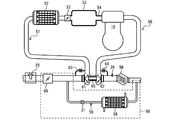
- FIG. 1 is a configuration diagram of an engine according to the first embodiment and the periphery thereof.
- the engine 10 as an example of the “internal combustion engine” is, for example, a spark-ignition multi-cylinder engine having four cylinders.
- the combustion chamber 40 (see FIG. 2) of each cylinder communicates with the intake system 51 on the upstream side and communicates with the exhaust system 55 on the downstream side.
- the intake system 51 includes an air flow sensor 23, a negative pressure generating valve 60, a compressor 61, an intercooler 52, an electronically controlled throttle valve 22, a collector 53, and an intake manifold 54 in this order from the upstream side.
- the air flow sensor 23 detects the amount of intake air.
- the negative pressure generating valve 60 regulates the flow rate of intake air.
- the compressor 61 compresses the intake air.
- the pipes upstream and downstream of the compressor 61 are connected via a pipe provided with a recirculation valve 63 so that the intake air bypasses the compressor 61.
- the recirculation valve 63 bypasses the compressor 61 to adjust the amount of intake air flowing.
- the intercooler 52 cools the intake air.
- the electronically controlled throttle valve 22 regulates the flow rate of intake air to the combustion chamber 40.
- the collector 53 reduces the flow rate of the intake air to level the increase and decrease.
- the intake manifold 54 distributes intake air to the combustion chamber 40 of each cylinder.
- the exhaust system 55 includes a turbine 62, an air-fuel ratio sensor 26, and a three-way catalyst 56 in order from the upstream side.
- the turbine 62 is connected to a compressor 61 disposed in the intake system 51 via a shaft 65.
- the turbine 62 rotates and the compressor 61 starts supercharging.
- the piping upstream and downstream of the turbine 62 is connected via piping provided with a waste gate valve 64 so that the exhaust gas bypasses the turbine 62.
- the waste gate valve 64 bypasses the turbine 62 and regulates the exhaust gas flowing.
- the air-fuel ratio sensor 26 detects an air-fuel ratio (A / F: Air / fuel) from the oxygen concentration in the exhaust gas.
- the three-way catalyst 56 is, for example, a carrier of alumina and ceria coated with platinum and palladium to purify the exhaust gas.
- the EGR Exhaust Gas Recirculation
- the EGR system 66 includes an EGR cooler 58, an EGR temperature sensor 59, and an EGR valve 31 in order from the upstream side.
- the EGR cooler 58 cools the EGR gas (exhaust gas).
- the EGR temperature sensor 59 measures the temperature of the EGR gas.
- the EGR valve 31 adjusts the amount of recirculation of the EGR gas.
- Exhaust gas from the exhaust system 55 flows from the exhaust system 55 to the EGR system 66 downstream of the three-way catalyst 56, and the high temperature EGR gas flowing to the EGR system 66 is cooled via the EGR cooler 58.
- the cooled EGR gas is adjusted to a predetermined flow rate through the EGR valve 31 and then mixed with the intake air upstream of the compressor 61 in the intake system 51.
- FIG. 2 is an overall configuration diagram of an internal combustion engine system.
- the internal combustion engine system 1 includes an engine 10 and an ECU (Engine Control Unit) 33 as an example of a “determination unit” and an “air-fuel ratio control unit”.
- ECU Engine Control Unit
- the engine 10 has a crankshaft 11 and transmits energy of combustion and explosion of the combustible mixture from the piston 15 to the crankshaft 11 via the connecting rod 16 to generate rotational driving force.
- a ring gear integrated with a drive plate for transmitting a driving force to the transmission 32, and a torque converter (none of which are shown) are attached.
- the output of the torque converter is input to the transmission 32.
- the driving force of the engine 10 is transmitted from the drive shaft (not shown) to the tire via the transmission 32 and transmitted to the road surface.
- the engine 10 may be a drive power source for causing the vehicle to travel, and examples include a port injection type or a cylinder injection type gasoline engine, a diesel engine, and the like.
- crankshaft pulley 11a for driving a belt of accessories is attached.
- crank angle signal plate 12 for detecting an angle (crank angle) of the crankshaft 11 is attached to the crankshaft 11.
- a predetermined concavo-convex pattern for detecting a crank angle signal is engraved on the circumference of the crank angle signal plate 12.
- a crank angle sensor 13 is attached near the outer periphery of the crank angle signal plate 12.
- the crank angle sensor 13 detects a concavo-convex pattern inscribed on the circumference of the crank angle signal plate 12 and outputs it to the ECU 33 as a pulse signal.
- the ECU 33 calculates the crank angle and the rotational speed (rotational speed) of the engine 10 based on the pulse signal input from the crank angle sensor 13.
- a hole penetrating to the combustion chamber 40 is provided in the upper part of the engine 10, and an in-cylinder pressure sensor 41 for detecting the pressure in the combustion chamber 40 is inserted through the through hole.
- the output of the in-cylinder pressure sensor 41 is amplified by the charge amplifier 42 and input to the ECU 33.
- a spark plug 28 and an injector 29 are disposed at the top of the engine 10. The spark plug 28 ignites the mixture in the combustion chamber 40 when supplied with high voltage from the ignition coil 27.
- the injector 29 injects fuel into the combustion chamber 40.
- the ECU 33 receives signals from the cam angle sensor 18, the accelerator opening sensor 19, the throttle opening sensor 21, the cooling water temperature sensor 24, and the intake air temperature sensor 25 in addition to the above-described sensors.
- the cam angle sensor 18 detects the unevenness pattern of the cam angle signal plate 17 attached to the tip of a camshaft for driving the intake valve and the exhaust valve of the combustion chamber 40, and performs cylinder discrimination.
- An accelerator opening sensor 19 detects the amount of depression of an accelerator pedal 20 in the driver's cabin.
- the throttle opening degree sensor 21 detects the opening degree of the electronically controlled throttle valve 22.
- the coolant temperature sensor 24 detects the temperature of coolant of the engine 10.
- the intake air temperature sensor 25 detects the temperature of the intake air.
- the ECU 33 controls the electronically controlled throttle valve 22, the ignition coil 27, the injector 29, the high pressure fuel pump 30, and the EGR valve 31.
- the high pressure fuel pump 30 supplies fuel.
- FIG. 3 is a block diagram showing the configuration of the ECU.
- the ECU 33 includes an input circuit 33a, an input / output port 33b, a RAM 33c, a ROM 33d, and a CPU 33e.
- the input circuit 33a includes a crank angle sensor 13, a cam angle sensor 18, an in-cylinder pressure sensor 41, an accelerator opening sensor 19, a throttle opening sensor 21, an air flow sensor 23, a coolant temperature sensor 24, an intake air temperature sensor 25, And a signal from the air-fuel ratio sensor 26 is input.
- the signals input from each sensor are not limited to these.
- Signals input from the respective sensors are sent to input ports in the input / output port 33b.
- the value sent to the input port of the input / output port 33b is stored in the RAM 33c and is arithmetically processed by the CPU 33e.
- a control program in which the contents of arithmetic processing are described is written in advance in the ROM 33 d.
- the value calculated according to the control program is stored in the RAM 33c, and then sent to the output port in the input / output port 33b to be sent to each actuator via each drive circuit.
- the ECU 33 according to this embodiment has an electronic control throttle drive circuit 33f, an injector drive circuit 33g, an ignition output (drive) circuit 33h, a high pressure fuel pump drive circuit 33i, and an EGR valve drive circuit 33j as drive circuits.
- the electronically controlled throttle drive circuit 33 f drives the electronically controlled throttle valve 22.
- the injector drive circuit 33 g drives the injector 29.
- the ignition output circuit 33 h drives the ignition coil 27.
- the high pressure fuel pump drive circuit 33i drives the high pressure fuel pump 30.
- the EGR valve drive circuit 33 j drives the EGR valve 31.
- the ECU 33 according to the present embodiment includes the drive circuits 33f to 33j. However, the present invention is not limited to this.
- the ECU 33 may include any one of the drive circuits 33f to 33j.
- crank angle detected by the crank angle sensor 13 and the in-cylinder pressure detected by the in-cylinder pressure sensor 41 corresponding to the crank angle are measured. These measured data are processed by the CPU 33 e and temporarily stored in the RAM 33 c as cylinder pressure data together with the crank angle for each combustion cycle.
- the ECU 33 compares the parameter indicating the combustion stability calculated based on the in-cylinder pressure signal described above with the determination threshold value, and when the combustion stability is ensured, the current target air-fuel ratio (target air-fuel ratio ) Has a function to shift to the lean side (decrease the fuel injection amount). On the other hand, the ECU 33 compares the parameter indicating the combustion stability with the determination threshold value to determine the target air-fuel ratio, and when it is determined that the combustion stability is decreasing, the current is used to secure the combustion stability. It has a function of shifting the target air-fuel ratio to the rich side (increasing the fuel injection amount).
- the ECU 33 calculates the amount of fuel corresponding to the amount of intake air measured by the air flow sensor 23, and controls the injector 29 so as to obtain the calculated amount of fuel.
- the ECU 33 starts fuel injection by the injector 29 at a timing when the crank angle indicated by the signal of the crank angle sensor 13 described above becomes a preset crank angle.
- the injector 29 injects fuel
- the drawn air and the fuel injected from the injector 29 are mixed to form a combustible mixture.
- a high voltage boosted by the ignition coil 27 is applied to the spark plug 28 at a timing when the crank angle detected by the crank angle sensor 13 becomes the crank angle preset by the ECU 33.
- the combustible mixture in the cylinder is ignited to burn and explode.
- lean burn combustion As one of the fuel consumption reducing techniques.
- the air fuel ratio should be operated as lean combustion state (lean burn) such as “20 or more” after taking measures to reduce NOx such as catalyst etc, combustion chamber shape, and optimization of injector spray etc.
- lean burn state
- Technology to reduce fuel consumption depending on engine performance, fuel properties, variations among cylinders, operating conditions, etc., there is a limit to the air-fuel ratio that can be operated as lean burn. For this reason, in the vicinity of the lean limit, the combustion generated torque fluctuates and becomes unstable, and it is transmitted as an unpleasant vibration to the driver and the passenger via the drive system.
- a method of indirectly detecting the combustion stability there is a method of measuring distortion or vibration of the cylinder outer wall and passing the measured value through a filter to convert it into a torque, and filtering the rotational fluctuation of the crankshaft 11 to convert it into a torque There is a way to take statistics.
- a pressure sensor is attached to the spark plug 28 or the cylinder head of the engine 10 to directly measure the pressure in the cylinder, and the indicated mean effective pressure (IMEP: Indicated Mean Effective Pressure) There is a way to convert to).
- the pressure in the cylinder is directly measured, and a crank angle value ⁇ Pmax indicating a maximum pressure value of the indicated mean effective pressure IMEP and the indicated mean effective pressure IMEP is extracted to detect the combustion stability.
- a sensor element for detecting distortion is attached to the tip of the in-cylinder pressure sensor 41 of each cylinder on the combustion chamber 40 side.
- the sensor element When the pressure in the combustion chamber 40 changes, the sensor element outputs a charge signal according to the pressure change. Since the charge signal output from the sensor element is minute, it is amplified by the charge amplifier 42, converted into a voltage signal (for example, 0 to 5 V), and output to the ECU 33.
- the ECU 33 calculates the in-cylinder pressure by multiplying the voltage input from the charge amplifier 42 by the conversion coefficient corresponding to the sensor characteristic.
- the timing at which the in-cylinder pressure is calculated is set to each crank angle (for example, every 10 °) detected by the crank angle sensor 13.
- the calculation result of the in-cylinder pressure corresponding to each crank angle is stored in the RAM 33 c.
- FIG. 4 is a P- ⁇ diagram showing an example of a change in in-cylinder pressure of one combustion cycle.
- the vertical axis shows the in-cylinder pressure Pi
- the horizontal axis shows a crank angle ⁇
- the exhaust valve When shifting to the exhaust stroke, the exhaust valve opens and the piston 15 turns upward to exhaust the exhaust gas, so the in-cylinder pressure Pi becomes a pressure near the atmospheric pressure. As described above, the in-cylinder pressure Pi becomes the maximum pressure Pmax at the time of combustion and explosion.
- the crank angle ⁇ at which the maximum pressure Pmax occurs is set to ⁇ Pmax, and the standard deviation ⁇ Pmax for a relatively small number of combustion cycles (for example, the last five cycles) is determined to determine the combustion stability.
- Use as a parameter for The relatively small number of combustion cycles is preferably 2 cycles or more and less than 100 combustion cycles.
- FIG. 5 is a flowchart of a standard deviation calculation process for obtaining ⁇ Pmax.
- the ECU 33 takes in the crank angle and the in-cylinder pressure data corresponding to the crank angle (step S11). The ECU 33 determines whether one combustion cycle has ended (step S12). If the determination result of step S12 is false (S12: NO), the process returns to step S11. If the determination result of step S12 is true (S12: YES), the process proceeds to step S13.
- the ECU 33 extracts a crank angle ⁇ Pmax at which the in-cylinder pressure data becomes maximum from the crank angle and the in-cylinder pressure data taken in (step S13).
- the ECU 33 stores the ⁇ Pmax extracted in step S13 in the RAM 33c (step S14). The ECU 33 determines whether ⁇ Pmax of a plurality of combustion cycles (five cycles in the example of FIG.
- step S15 has been extracted (step S15). If the determination result of step S15 is false (S15: NO), the process returns to step S11. If the determination result in step S15 is true (S15: YES), the ECU 33 calculates a standard deviation ⁇ Pmax of ⁇ Pmax (step S16). The ECU 33 stores the ⁇ Pmax calculated in step S16 in the RAM 33c (step S17).
- FIG. 6 is a diagram for explaining a method of obtaining IMEP from the P- ⁇ diagram.
- the stroke volume Vs is calculated based on the crank angle ⁇ , the bore, and the stroke of the horizontal axis of the P- ⁇ diagram shown on the left side of FIG. 6 to obtain a PV diagram.
- the area shown by the shaded portion of the PV diagram shown on the right of FIG. 6 is the indicated mean effective pressure IMEP.
- the indicated average effective pressure IMEP is expressed by the following equation (1) when the stroke volume is Vs, the in-cylinder pressure is Pi, and the combustion chamber volume change is dV.
- the fluctuation rate CPi of the indicated average effective pressure IMEP is expressed by the following equation (2).
- the standard deviation of the values obtained by sampling the indicated mean effective pressure IMEP over a plurality of combustion cycles (for example, 400 cycles) is ⁇ IMEP, and the average value is Ave IMEP.
- the variation rate CPi of the indicated mean effective pressure IMEP is used as a parameter for determining the combustion stability of a long period (span) in a relatively large number of combustion cycles of 100 cycles or more.
- the relatively large number of combustion cycles has more combustion cycles than the relatively small number of combustion cycles, and is preferably 100 cycles or more and less than 700 cycles.
- FIG. 7 is a flowchart of the process of calculating the variation rate of the indicated mean effective pressure for obtaining ⁇ IMEP and CPi.
- the ECU 33 takes in the crank angle and the in-cylinder pressure data corresponding to the crank angle (step S21).
- the ECU 33 determines whether one combustion cycle has ended (step S22). If the determination result of step S22 is false (S22: NO), the process returns to S21. If the determination result of S22 is true (S22: YES), the process proceeds to step S23.
- the ECU 33 calculates the indicated mean effective pressure IMEP according to the above-mentioned equation 1 (step S23).
- the ECU 33 calculates a difference ⁇ IMEP from the immediately preceding combustion cycle (step S24).
- the ECU 33 stores the indicated average effective pressure IMEP calculated in step S23 and the ⁇ IMEP calculated in step S24 in the RAM 33c (step S25).
- the ECU 33 determines whether or not the indicated mean effective pressure IMEP of a plurality of combustion cycles (400 cycles in the example of FIG. 7) has been calculated (step S26). If the determination result of step S26 is false (S26: NO), the process returns to step S21. If the determination result in step S26 is true (S26: YES), the ECU 33 calculates the standard deviation ⁇ IMEP of the indicated mean effective pressure IMEP and the average value AveIMEP of the indicated mean effective pressure IMEP for 400 cycles (step S27) ). The ECU 33 calculates a fluctuation rate CPi of the indicated mean effective pressure IMEP (step S28). The ECU 33 stores the variation rate CPi of the indicated mean effective pressure IMEP calculated in step S28 in the RAM 33c (step S29).
- FIG. 8 is a diagram showing an example of air-fuel ratio control based on CPi.
- FIG. 8 shows a state in which the temperature of the cooling water, the temperature of the intake air, the temperature of the fuel, and the like change while operating in the steady state, and the combustion state changes in a relatively long span.
- the ECU 33 calculates the fluctuation rate CPi of the indicated mean effective pressure IMEP with the number of combustion cycles required to calculate the parameter indicating the combustion stability (hereinafter referred to as the setting cycle) as 400 cycles, and the result indicates the combustion deterioration side
- the threshold value a1 it is determined that the combustion stability has decreased, and the air-fuel ratio is corrected to the rich side.
- the combustion stability is improved and the variation rate of the indicated mean effective pressure IMEP is reduced.
- the air-fuel ratio is corrected to the lean side when the combustion stability becomes stable as the determination threshold b1 on the combustion stable side becomes equal to or less.
- the correction amount of the air-fuel ratio differs depending on the absolute value of the deviation amount CPi-a1 from the determination threshold a1 or the deviation amount CPi-b1 from the determination threshold b1, and is large when the deviation amount is large and small when the deviation amount is small.
- FIG. 9 is a flowchart showing an example of air-fuel ratio control based on CPi.
- the ECU 33 reads the variation rate CPi of the indicated mean effective pressure IMEP calculated in the variation rate calculation process of the indicated mean effective pressure in FIG. 7 (step S31).
- the ECU 33 compares the variation rate CPi of the indicated mean effective pressure IMEP read in step S31 with the determination threshold a1 on the combustion deterioration side to determine whether the variation rate CPi of the indicated mean effective pressure IMEP is a1 or more. (Step S32). If the determination result in step S32 is true (S32: YES), the process proceeds to step S33.
- the ECU 33 increases the correction amount of the air-fuel ratio to the rich side as the absolute value of CPi-a1 increases (step S33).
- step S34 The ECU 33 determines whether the variation rate CPi of the indicated mean effective pressure IMEP is less than or equal to b1 by comparing the variation rate CPi of the indicated mean effective pressure IMEP read in step S31 with the determination threshold b1 of the combustion stabilization side Step S34). If the determination result of step S34 is true (S34: YES), the process proceeds to step S35. The ECU 33 increases the correction amount of the air-fuel ratio to the lean side as the absolute value of CPi-b1 increases (step S35). If the determination result of step S34 is false (S34: NO), the process proceeds to step S36. The ECU 33 keeps the air-fuel ratio correction amount at the previous correction amount (step S36). The ECU 33 controls the air-fuel ratio of the engine 10 so as to achieve the determined correction amount.
- the fluctuation rate CPi of the indicated average effective pressure IMEP with high accuracy in relatively many combustion cycles such as 400 cycles is calculated
- combustion stability can be secured and fuel consumption can be suppressed even near the combustion limit.
- FIG. 10 is a diagram showing the problem of air-fuel ratio control based on CPi.
- the transient engine A load change to 10 may occur, the fluctuation to the decrease side of the indicated mean effective pressure IMEP may increase, and the combustion stability may decrease.
- the ECU 33 can not correct the air-fuel ratio until the setting cycle necessary to calculate the fluctuation rate CPi of the indicated average effective pressure IMEP has elapsed. Therefore, the drivability is deteriorated without suppressing the vibration of the vehicle body due to the combustion deterioration and the misfire in the combustion cycle.
- the ECU 33 uses the fluctuation rate CPi of the indicated average effective pressure IMEP and a relatively small combustion cycle as a parameter indicating the combustion stability in order to cope with the transient change in the load on the engine 10.
- the parameter indicating the combustion stability is used.
- the standard deviation ⁇ Pmax of the crank angle ⁇ Pmax generating the maximum in-cylinder pressure Pmax or the difference with the indicated average effective pressure IMEP of the immediately preceding combustion cycle.
- ⁇ IMEP is used as a parameter indicating the combustion stability in a relatively small number of combustion cycles.
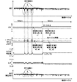
- FIG. 11 is a view showing an example of air-fuel ratio control according to the first embodiment.
- the combustion stability is judged using the fluctuation rate CPI of the indicated mean effective pressure IMEP as a parameter, the fluctuation rate CPi of the indicated mean effective pressure IMEP is calculated every 400 cycles, so the combustion temporarily deteriorates during that cycle. However, the air-fuel ratio can not be corrected immediately.
- the combustion stability is determined using the standard deviation ⁇ Pmax of the crank angle ⁇ Pmax that generates the maximum in-cylinder pressure Pmax or the difference ⁇ IMEP with the indicated average effective pressure IMEP of the immediately preceding combustion cycle as a parameter, it is relatively small.
- the combustion stability can be determined in the combustion cycle, and the air-fuel ratio can be corrected immediately.
- the fluctuation time of the indicated mean effective pressure IMEP can be kept short, and the vibration transmitted to the vehicle body and the occupant can be reduced to improve the drivability.
- FIG. 12 is a flowchart showing an example of air-fuel ratio control according to the first embodiment.
- the ECU 33 generates the maximum cylinder pressure Pmax calculated in the standard deviation calculation process of FIG. 5 and the fluctuation rate CPi of the indicated average effective pressure IMEP calculated in the fluctuation rate calculation process of the illustrated average effective pressure of FIG. And the standard deviation .sigma..theta.Pmax of each are read (step S41).
- the ECU 33 determines that the variation coefficient CPi of the indicated average effective pressure IMEP is equal to or higher than the determination threshold a1 on the combustion deterioration side or the standard deviation ⁇ Pmax of the crank angle ⁇ Pmax that generates the maximum in-cylinder pressure Pmax is the determination threshold a2 on the combustion deterioration side (first setting Value) or not is determined (step S42).
- step S42 If the determination result of step S42 is true (S42: YES), the process proceeds to step S43.
- the ECU 33 corrects the air-fuel ratio to the rich side (f1) so that the larger the absolute value of CPi-a1 is, the larger the absolute value of CPi-a1 is when the fluctuation rate CPi of the indicated average effective pressure IMEP is equal to or higher than the determination threshold a1 on the combustion deterioration side.
- step S43 the correction amount (f2) to the rich side of the air-fuel ratio is determined (step S43). If the determination result of step S42 is false (S42: NO), the process proceeds to step S44.
- the ECU 33 determines that the variation coefficient CPi of the indicated average effective pressure IMEP is equal to or less than the determination threshold b1 on the combustion stable side, and the standard deviation ⁇ Pmax of the crank angle ⁇ Pmax that generates the maximum in-cylinder pressure Pmax indicates the combustion threshold side determination threshold b2 (third setting It is determined whether the value is less than or equal to (step S44). If the determination result in step S44 is true (S44: YES), the process proceeds to step S45.
- the ECU 33 determines the correction reference amount (g1) determined to be larger as the absolute value of CPi-b1 is larger, and the correction reference amount determined to be larger as the absolute value of ⁇ Pmax-b2 is larger g2) is determined, and the correction amount (g1 x g2) of the air-fuel ratio to the lean side is determined so that the larger the product of the correction reference amount (g1) and the correction reference amount (g2), the larger the air-fuel ratio becomes (step S45). ). If the determination result of step S44 is false (S44: NO), the process proceeds to step S46. The ECU 33 keeps the air-fuel ratio correction amount at the previous correction amount (step S46). The ECU 33 controls the air-fuel ratio of the engine 10 so as to achieve the determined correction amount.
- FIG. 13 is a flowchart showing an example of another air-fuel ratio control according to the first embodiment.
- the ECU 33 reads the variation rate CPi of the indicated average effective pressure IMEP calculated in the process of FIG. 7 and the difference ⁇ IMEP between the immediately preceding indicated effective pressure IMEP of the combustion cycle (step S51).
- the ECU 33 determines that the variation rate CPi of the indicated average effective pressure IMEP is equal to or greater than the determination threshold a1 on the combustion deterioration side or the difference ⁇ IMEP with the indicated average effective pressure IMEP of the immediately preceding combustion cycle is the determination threshold a3 on the combustion deterioration side (second set value ) Is judged (step S52). If the determination result of step S52 is true (S52: YES), the process proceeds to step S53.
- the ECU 33 corrects the air-fuel ratio to the rich side (f1) so that the larger the absolute value of CPi-a1 is, the larger the absolute value of CPi-a1 is when the fluctuation rate CPi of the indicated average effective pressure IMEP is equal to or higher than the determination threshold a1 on the combustion deterioration side. If the difference ⁇ IMEP with the indicated average effective pressure IMEP of the previous combustion cycle is equal to or greater than the determination threshold a3 on the combustion deterioration side, the air fuel ratio rich side is larger as the absolute value of ⁇ Pmax-b2 is larger.
- the amount of correction (f3) to be corrected is determined (step S53). If the determination result of step S52 is false (S52: NO), the process proceeds to step S54.
- the ECU 33 determines that the variation rate CPi of the indicated average effective pressure IMEP is equal to or less than the determination threshold b1 on the combustion stabilization side, and the difference ⁇ IMEP with the indicated average effective pressure IMEP of the immediately preceding combustion cycle is the determination threshold b3 on the combustion stabilization side (fourth set value ) Is determined (step S54). If the determination result of step S54 is true (S54: YES), the process proceeds to step S55.
- the ECU 33 determines the correction reference amount (g1) determined to be larger as the absolute value of CPi-b1 is larger, and the correction reference amount determined to be larger as the absolute value of ⁇ Pmax-b3 is larger g3) is determined, and the correction amount (g1 x g2) of the air-fuel ratio to the lean side is determined so that the larger the product of the correction reference amount (g1) and the correction reference amount (g3), the larger the air-fuel ratio becomes (step S55). ). If the determination result of step S54 is false (S44: NO), the process proceeds to step S56.
- the ECU 33 keeps the air-fuel ratio correction amount at the previous correction amount (step S56).
- the ECU 33 controls the air-fuel ratio of the engine 10 so as to achieve the determined correction amount.
- the correction amount of the air-fuel ratio to the rich side in these steps S43 and S53 and the correction amount to the lean side of the air-fuel ratio in steps S45 and S55 are absolute values of the difference between each parameter indicating combustion stability and the determination threshold. The bigger it is, the bigger it is. That is, when the deviation from each threshold value is large, the air-fuel ratio can be quickly shifted to the rich side or the lean side by increasing each correction amount to improve responsiveness, and combustion stability can be secured. it can. Furthermore, when the air-fuel ratio is shifted to the lean side, the fuel consumption can be reduced.
- a parameter indicating combustion stability having different characteristics is calculated.
- the deterioration of the combustion state due to the change of the transient operating condition can be promptly detected, and the air-fuel ratio control can be carried out at that stage, and the deterioration of the drivability is suppressed even in the lean limit region by the lean burn. Is possible.
- the increase of the combustion consumption can be suppressed by shifting the air-fuel ratio to the lean side.
- the ECU 33 according to the second embodiment differs from the ECU 33 according to the first embodiment only in the method of determining the correction amount of the air-fuel ratio, and the hardware configuration is the same as the ECU 33 according to the first embodiment. It is.
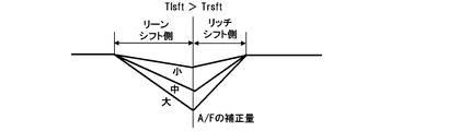
- FIG. 14 is a view for explaining the method of determining the air-fuel ratio correction amount according to the second embodiment.
- the load on the engine 10 may change according to the change of the throttle opening or the change of the EGR amount due to the accelerator operation of the driver.
- the ECU 33 changes the correction amount of the air-fuel ratio according to the referred change amount with reference to the change amount of either the throttle opening degree or the EGR opening degree.
- Each change amount is divided by the opening degree and the change speed, and when the opening degree is large and the change speed is fast, the correction amount is large, and when the opening degree is small and the change speed is slow, the correction amount is small.
- the ECU 33 sets the transition time Trsft on the rich shift side shorter than the transition time Tlsft on the lean shift side in order to place importance on the combustion stability.
- the ECU 33 according to the third embodiment is an example of shifting the air-fuel ratio to the lean side, and the hardware configuration is the same as that of the ECU 33 according to the first embodiment.
- FIG. 15 is a view for explaining the method of determining the air-fuel ratio correction amount according to the third embodiment.
- the change amount of either the throttle opening degree or the EGR opening degree is referred to, and the correction to the lean side of the air fuel ratio is performed as the referred change amount is larger. Increase the amount.
- the transition time Trsft on the rich shift side is set shorter than the transition time Tlsft on the lean shift side in order to emphasize combustion stability.
- the ECU 33 according to the fourth embodiment differs from the ECU 33 according to the first embodiment only in the correction period of the air-fuel ratio, and the hardware configuration is the same as that of the ECU 33 according to the first embodiment.
- FIG. 16 is a view for explaining the method of determining the air-fuel ratio correction amount according to the fourth embodiment.
- the ECU 33 increases the correction amount of the air-fuel ratio as the opening degree of the throttle or EGR is larger when the changing speeds of the throttle opening degree or the EGR opening degree are equal and the changing amounts are different.
- the present invention is not limited to the above-described embodiment, but includes various modifications.
- the above-described embodiment is described in detail to explain the present invention in an easy-to-understand manner, and is not necessarily limited to one having all the described configurations.
- part of the configuration of one embodiment can be replaced with the configuration of another embodiment, and the configuration of another embodiment can be added to the configuration of one embodiment.
- the ECU 33 uses the variation rate CPi of the indicated mean effective pressure IMEP and the parameter indicating the combustion stability in a relatively small combustion cycle as the parameters indicating the combustion stability. Not only this but ECU33 may use only a parameter which shows combustion stability by a comparatively few combustion cycle as a parameter which shows combustion stability.
- step S42 the ECU 33 determines that the standard deviation .sigma..theta.Pmax of the crank angle .theta.Pmax at which the fluctuation rate CPi of the indicated average effective pressure IMEP is the determination threshold a1 or more of the combustion deterioration side or the maximum in-cylinder pressure Pmax It was judged whether it was more than the judgment threshold a2 of the side.
- the ECU 33 is not limited to this, and the variation coefficient CPi of the indicated average effective pressure IMEP is the determination threshold a1 or more of the combustion deterioration side of this CPi, and the standard deviation ⁇ Pmax of the crank angle ⁇ Pmax generating the maximum in-cylinder pressure Pmax is the combustion deterioration side It may be determined whether or not the determination threshold a2 of
- step S52 the ECU 33 determines that the variation rate CPi of the indicated average effective pressure IMEP is the determination threshold a1 or more of the combustion deterioration side or the difference ⁇ IMEP with the indicated average effective pressure IMEP of the immediately preceding combustion cycle is the combustion deterioration side. It was determined whether it was more than determination threshold a3 of. Not limited to this, the ECU 33 determines that the variation rate CPi of the indicated average effective pressure IMEP is equal to or greater than the determination threshold a1 on the combustion deterioration side, and the difference ⁇ IMEP with the indicated average effective pressure IMEP of the immediately preceding combustion cycle indicates the combustion deterioration side threshold value a3. It may be determined whether it is above or not.
- the previous combustion cycle is the previous combustion cycle.
- the previous combustion cycle may be a combustion cycle two or more combustion cycles earlier.
- the ECU 33 refers to the amount of change in either the throttle opening or the amount of change in the EGR opening, and corrects the air fuel ratio according to the amount of change. I changed the amount.
- the ECU 33 may change the correction amount of the air-fuel ratio according to the amount of change of the throttle opening degree and the amount of change of the EGR opening degree.
- the ECU 33 when correcting the air-fuel ratio, sets the transition time Trsft on the rich shift side shorter than the transition time Tlsft on the lean shift side.
- the ECU 33 may make the transition time Tlsft on the lean shift side and the transition time Trsft on the rich shift side the same period.
Landscapes
- Engineering & Computer Science (AREA)
- Chemical & Material Sciences (AREA)
- Combustion & Propulsion (AREA)
- Mechanical Engineering (AREA)
- General Engineering & Computer Science (AREA)
- Combined Controls Of Internal Combustion Engines (AREA)
- Electrical Control Of Air Or Fuel Supplied To Internal-Combustion Engine (AREA)
Abstract
L'objet de la présente invention est de réduire le raté d'allumage et la fluctuation de couple dus à une détérioration rapide de la combustion dans un moteur à combustion interne. À cet effet, une unité de commande électronique destinée à un moteur dans lequel du carburant est brûlé dans un cylindre comprend : une unité de détermination qui détermine un rapport air-carburant cible pour le moteur sur la base d'une variation (σθPmax) de l'angle de vilebrequin pendant un nombre relativement petit de cycles de combustion, ou une différence (ΔIMEP) de pression efficace moyenne indiquée à partir du cycle de combustion précédent ; et une unité de commande de rapport air-carburant qui amène le rapport air-carburant du moteur à correspondre au rapport air-carburant cible déterminé par l'unité de détermination. L'unité de détermination décale le rapport air-carburant cible vers le côté riche si la variation (σθPmax) a dépassé une première valeur de réglage (a2) ou si la différence (ΔIMEP) a dépassé une seconde valeur de réglage (a3).
Priority Applications (3)
| Application Number | Priority Date | Filing Date | Title |
|---|---|---|---|
| JP2019543444A JPWO2019058728A1 (ja) | 2017-09-21 | 2018-07-18 | 内燃機関の制御装置、及び内燃機関の制御方法 |
| DE112018004225.1T DE112018004225B4 (de) | 2017-09-21 | 2018-07-18 | Brennkraftmaschinen-Steuervorrichtung und Brennkraftmaschinen-Steuerverfahren |
| US16/645,580 US20200300194A1 (en) | 2017-09-21 | 2018-07-18 | Internal Combustion Engine Control Device and Internal Combustion Engine Control Method |
Applications Claiming Priority (2)
| Application Number | Priority Date | Filing Date | Title |
|---|---|---|---|
| JP2017-180909 | 2017-09-21 | ||
| JP2017180909 | 2017-09-21 |
Publications (1)
| Publication Number | Publication Date |
|---|---|
| WO2019058728A1 true WO2019058728A1 (fr) | 2019-03-28 |
Family
ID=65809652
Family Applications (1)
| Application Number | Title | Priority Date | Filing Date |
|---|---|---|---|
| PCT/JP2018/026816 Ceased WO2019058728A1 (fr) | 2017-09-21 | 2018-07-18 | Dispositif de commande de moteur à combustion interne et procédé de commande de moteur à combustion interne |
Country Status (4)
| Country | Link |
|---|---|
| US (1) | US20200300194A1 (fr) |
| JP (1) | JPWO2019058728A1 (fr) |
| DE (1) | DE112018004225B4 (fr) |
| WO (1) | WO2019058728A1 (fr) |
Families Citing this family (1)
| Publication number | Priority date | Publication date | Assignee | Title |
|---|---|---|---|---|
| JP7089900B2 (ja) * | 2018-02-26 | 2022-06-23 | 日立Astemo株式会社 | 内燃機関の制御装置および内燃機関の制御方法 |
Citations (6)
| Publication number | Priority date | Publication date | Assignee | Title |
|---|---|---|---|---|
| JPH0320596B2 (fr) * | 1982-10-08 | 1991-03-19 | Toyota Motor Co Ltd | |
| JP2000227037A (ja) * | 1999-02-05 | 2000-08-15 | Mitsubishi Electric Corp | 筒内噴射式内燃機関の制御装置 |
| JP2002276456A (ja) * | 2001-03-19 | 2002-09-25 | Unisia Jecs Corp | 内燃機関の燃焼制御装置 |
| JP2003222039A (ja) * | 2002-01-30 | 2003-08-08 | Mazda Motor Corp | エンジンの制御装置 |
| JP2007303353A (ja) * | 2006-05-11 | 2007-11-22 | Hitachi Ltd | エンジンの制御装置 |
| JP2016118111A (ja) * | 2014-12-18 | 2016-06-30 | トヨタ自動車株式会社 | 内燃機関の制御装置 |
Family Cites Families (7)
| Publication number | Priority date | Publication date | Assignee | Title |
|---|---|---|---|---|
| JP3471373B2 (ja) * | 1992-07-10 | 2003-12-02 | 日本特殊陶業株式会社 | ガソリン機関の燃焼制御装置 |
| JP2822804B2 (ja) * | 1992-08-28 | 1998-11-11 | 日産自動車株式会社 | 内燃機関の制御装置 |
| DE4444972C2 (de) | 1993-12-17 | 2000-08-31 | Fuji Heavy Ind Ltd | Elektronisches Steuerverfahren und Steuersystem für einen Motor |
| JPH09264183A (ja) | 1996-03-29 | 1997-10-07 | Mazda Motor Corp | エンジンの燃焼状態判別方法、エンジンの制御方法及び同装置 |
| JP2000170572A (ja) | 1998-12-07 | 2000-06-20 | Honda Motor Co Ltd | 内燃機関の空燃比制御装置 |
| JP3743607B2 (ja) * | 1999-12-02 | 2006-02-08 | 株式会社デンソー | 内燃機関の制御装置 |
| JP6213532B2 (ja) | 2015-08-04 | 2017-10-18 | トヨタ自動車株式会社 | 内燃機関の制御装置 |
-
2018
- 2018-07-18 DE DE112018004225.1T patent/DE112018004225B4/de not_active Expired - Fee Related
- 2018-07-18 JP JP2019543444A patent/JPWO2019058728A1/ja active Pending
- 2018-07-18 US US16/645,580 patent/US20200300194A1/en not_active Abandoned
- 2018-07-18 WO PCT/JP2018/026816 patent/WO2019058728A1/fr not_active Ceased
Patent Citations (6)
| Publication number | Priority date | Publication date | Assignee | Title |
|---|---|---|---|---|
| JPH0320596B2 (fr) * | 1982-10-08 | 1991-03-19 | Toyota Motor Co Ltd | |
| JP2000227037A (ja) * | 1999-02-05 | 2000-08-15 | Mitsubishi Electric Corp | 筒内噴射式内燃機関の制御装置 |
| JP2002276456A (ja) * | 2001-03-19 | 2002-09-25 | Unisia Jecs Corp | 内燃機関の燃焼制御装置 |
| JP2003222039A (ja) * | 2002-01-30 | 2003-08-08 | Mazda Motor Corp | エンジンの制御装置 |
| JP2007303353A (ja) * | 2006-05-11 | 2007-11-22 | Hitachi Ltd | エンジンの制御装置 |
| JP2016118111A (ja) * | 2014-12-18 | 2016-06-30 | トヨタ自動車株式会社 | 内燃機関の制御装置 |
Also Published As
| Publication number | Publication date |
|---|---|
| US20200300194A1 (en) | 2020-09-24 |
| JPWO2019058728A1 (ja) | 2020-10-15 |
| DE112018004225B4 (de) | 2023-03-16 |
| DE112018004225T5 (de) | 2020-05-07 |
Similar Documents
| Publication | Publication Date | Title |
|---|---|---|
| US6994077B2 (en) | Control system for internal combustion engine | |
| KR101781720B1 (ko) | 내연 기관의 제어 장치 | |
| US7950369B2 (en) | Internal combustion engine controlling apparatus | |
| US7861690B2 (en) | Device and method for controlling internal combustion engine | |
| US6990934B2 (en) | Internal combustion engine having variable compression ratio mechanism and control method therefor | |
| US7401591B2 (en) | Control system for internal combustion engine | |
| JP4050229B2 (ja) | 4ストロークエンジンの制御装置及び制御方法 | |
| EP3150832B1 (fr) | Dispositif de commande de moteur diesel et procédé de commande | |
| WO2005003538A1 (fr) | Dispositif et procede servant a commander un moteur a combustion interne | |
| US20150275810A1 (en) | Apparatus and method for controlling diesel engine | |
| JP2009062862A (ja) | 内燃機関の燃料噴射制御装置 | |
| JP3775942B2 (ja) | 内燃機関の燃料噴射制御装置 | |
| JPWO2003038262A1 (ja) | 4ストロークエンジンの大気圧検出装置及び方法 | |
| US20070235009A1 (en) | Control apparatus for direct injection type spark ignition internal combustion engine | |
| WO2019058728A1 (fr) | Dispositif de commande de moteur à combustion interne et procédé de commande de moteur à combustion interne | |
| JP4277623B2 (ja) | 可変圧縮比機構付き内燃機関の点火時期制御装置 | |
| JP2004316545A (ja) | 圧縮着火式内燃機関の気筒別制御装置 | |
| JP4735497B2 (ja) | 圧縮着火式内燃機関の燃料セタン価判別システム | |
| US20160369729A1 (en) | Control apparatus and control method for internal combustion engine | |
| JP4615501B2 (ja) | 内燃機関の制御装置 | |
| JP2006144672A (ja) | 内燃機関の制御装置および制御方法 | |
| JP2004293471A (ja) | 燃焼方式切替可能な内燃機関の吸気絞り弁制御装置 | |
| JP2013224616A (ja) | 内燃機関のトルク推定装置および運転制御装置 | |
| JP2003148182A (ja) | 内燃機関の制御装置 | |
| JP3653185B2 (ja) | 筒内噴射内燃機関の燃料噴射時期制御装置 |
Legal Events
| Date | Code | Title | Description |
|---|---|---|---|
| 121 | Ep: the epo has been informed by wipo that ep was designated in this application |
Ref document number: 18859113 Country of ref document: EP Kind code of ref document: A1 |
|
| ENP | Entry into the national phase |
Ref document number: 2019543444 Country of ref document: JP Kind code of ref document: A |
|
| 122 | Ep: pct application non-entry in european phase |
Ref document number: 18859113 Country of ref document: EP Kind code of ref document: A1 |