WO2019059141A1 - Unité d'embrayage - Google Patents
Unité d'embrayage Download PDFInfo
- Publication number
- WO2019059141A1 WO2019059141A1 PCT/JP2018/034308 JP2018034308W WO2019059141A1 WO 2019059141 A1 WO2019059141 A1 WO 2019059141A1 JP 2018034308 W JP2018034308 W JP 2018034308W WO 2019059141 A1 WO2019059141 A1 WO 2019059141A1
- Authority
- WO
- WIPO (PCT)
- Prior art keywords
- output
- rotational torque
- output shaft
- input
- outer ring
- Prior art date
- Legal status (The legal status is an assumption and is not a legal conclusion. Google has not performed a legal analysis and makes no representation as to the accuracy of the status listed.)
- Ceased
Links
Images


Classifications
-
- B—PERFORMING OPERATIONS; TRANSPORTING
- B60—VEHICLES IN GENERAL
- B60N—SEATS SPECIALLY ADAPTED FOR VEHICLES; VEHICLE PASSENGER ACCOMMODATION NOT OTHERWISE PROVIDED FOR
- B60N2/00—Seats specially adapted for vehicles; Arrangement or mounting of seats in vehicles
- B60N2/02—Seats specially adapted for vehicles; Arrangement or mounting of seats in vehicles the seat or part thereof being movable, e.g. adjustable
- B60N2/04—Seats specially adapted for vehicles; Arrangement or mounting of seats in vehicles the seat or part thereof being movable, e.g. adjustable the whole seat being movable
- B60N2/16—Seats specially adapted for vehicles; Arrangement or mounting of seats in vehicles the seat or part thereof being movable, e.g. adjustable the whole seat being movable height-adjustable
-
- B—PERFORMING OPERATIONS; TRANSPORTING
- B60—VEHICLES IN GENERAL
- B60N—SEATS SPECIALLY ADAPTED FOR VEHICLES; VEHICLE PASSENGER ACCOMMODATION NOT OTHERWISE PROVIDED FOR
- B60N2/00—Seats specially adapted for vehicles; Arrangement or mounting of seats in vehicles
- B60N2/90—Details or parts not otherwise provided for
-
- F—MECHANICAL ENGINEERING; LIGHTING; HEATING; WEAPONS; BLASTING
- F16—ENGINEERING ELEMENTS AND UNITS; GENERAL MEASURES FOR PRODUCING AND MAINTAINING EFFECTIVE FUNCTIONING OF MACHINES OR INSTALLATIONS; THERMAL INSULATION IN GENERAL
- F16D—COUPLINGS FOR TRANSMITTING ROTATION; CLUTCHES; BRAKES
- F16D15/00—Clutches with wedging balls or rollers or with other wedgeable separate clutching members
-
- F—MECHANICAL ENGINEERING; LIGHTING; HEATING; WEAPONS; BLASTING
- F16—ENGINEERING ELEMENTS AND UNITS; GENERAL MEASURES FOR PRODUCING AND MAINTAINING EFFECTIVE FUNCTIONING OF MACHINES OR INSTALLATIONS; THERMAL INSULATION IN GENERAL
- F16D—COUPLINGS FOR TRANSMITTING ROTATION; CLUTCHES; BRAKES
- F16D41/00—Freewheels or freewheel clutches
- F16D41/06—Freewheels or freewheel clutches with intermediate wedging coupling members between an inner and an outer surface
- F16D41/064—Freewheels or freewheel clutches with intermediate wedging coupling members between an inner and an outer surface the intermediate members wedging by rolling and having a circular cross-section, e.g. balls
- F16D41/066—Freewheels or freewheel clutches with intermediate wedging coupling members between an inner and an outer surface the intermediate members wedging by rolling and having a circular cross-section, e.g. balls all members having the same size and only one of the two surfaces being cylindrical
- F16D41/067—Freewheels or freewheel clutches with intermediate wedging coupling members between an inner and an outer surface the intermediate members wedging by rolling and having a circular cross-section, e.g. balls all members having the same size and only one of the two surfaces being cylindrical and the members being distributed by a separate cage encircling the axis of rotation
-
- F—MECHANICAL ENGINEERING; LIGHTING; HEATING; WEAPONS; BLASTING
- F16—ENGINEERING ELEMENTS AND UNITS; GENERAL MEASURES FOR PRODUCING AND MAINTAINING EFFECTIVE FUNCTIONING OF MACHINES OR INSTALLATIONS; THERMAL INSULATION IN GENERAL
- F16D—COUPLINGS FOR TRANSMITTING ROTATION; CLUTCHES; BRAKES
- F16D41/00—Freewheels or freewheel clutches
- F16D41/06—Freewheels or freewheel clutches with intermediate wedging coupling members between an inner and an outer surface
- F16D41/08—Freewheels or freewheel clutches with intermediate wedging coupling members between an inner and an outer surface with provision for altering the freewheeling action
- F16D41/10—Freewheels or freewheel clutches with intermediate wedging coupling members between an inner and an outer surface with provision for altering the freewheeling action with self-actuated reversing
Definitions
- the present invention is provided with an input-side clutch portion to which a rotational torque is input, and an output-side clutch portion for transmitting the rotational torque from the input-side clutch portion to the output side and blocking the rotational torque from the output side. It relates to a clutch unit.
- a clutch portion is disposed between an input member and an output member.
- the clutch unit is configured to control transmission and interruption of rotational torque by engaging and disengaging an engager between the input member and the output member.
- the clutch unit disclosed in Patent Document 1 transmits to the output side the rotational torque from the lever side clutch portion to which the rotational torque is input by the lever operation and the rotational torque from the lever side clutch portion, and also transmits the rotational torque from the output side. And a brake-side clutch unit that shuts off.
- the lever side clutch portion engages and disengages the outer ring to which the rotational torque is input by the lever operation, the inner ring transmitting the rotational torque input from the outer ring to the brake side clutch portion, and the clearance between the outer ring and the inner ring
- the main part is constituted by the cylindrical roller which controls transmission and interception of the rotational torque from an outer ring by this.
- the brake-side clutch portion includes an inner ring to which rotational torque from the lever-side clutch portion is input, an output shaft to which rotational torque from the inner ring is output, an outer ring whose rotation is constrained, a gap between the output shaft and the outer ring
- the main part is constituted by cylindrical rollers which control the interruption of the rotational torque from the output shaft and the transmission of the rotational torque from the inner ring by the engagement and disengagement of the clearances.
- Patent No. 5207779 gazette
- the present invention has been proposed in view of the problems described above, and the purpose of the present invention is to securely lock the output shaft even if the rotational torque in the forward and reverse directions is continuously reversely input to the output shaft. It is providing the clutch unit provided with the structure obtained.
- the clutch unit according to the present invention transmits to the output side the rotational torque from the input-side clutch portion that controls transmission and interruption of the input rotational torque, and the input-side clutch portion, and is reversely input from the output side It has a basic configuration including an output side clutch unit that shuts off the rotational torque.
- the output-side clutch unit of the present invention includes a stationary member whose rotation is restricted, and an output member whose rotational output is output, and an output member when rotational torque is interrupted.
- a gear member is engaged with the stationary member, and the gear member has a module size of 0.4 to 0.8 and a gear number of 60 to 100. It is characterized by having a tooth portion defined in pieces.
- the stationary member by attaching the gear member to the stationary member, when the output member is locked, even if the rotational torque in the forward direction and the rotational torque in the reverse direction are alternately continued and continuously input to the output member, the stationary member
- the gear member attached to the gear is engaged with the output member, whereby the output member can be reliably locked.
- the gear member in the present invention has a toothed part having a module of 0.4 to 0.8 and a tooth number of 60 to 100, so that the gear member meshes with the output member at the time of interruption of the rotational torque. Good operability can be ensured in releasing the meshing state with the output member at the time of transmission of torque.
- the output side clutch portion is configured to interrupt the rotational torque reversely input from the output member and transmit the rotational torque input from the input side clutch portion by engagement and disengagement between the stationary member and the output member.
- the input-side clutch portion and the output-side clutch portion in the present invention preferably have a structure incorporated in a seat lifter portion for a vehicle.
- the gear member by providing the gear member to the stationary member, when the output member is locked, even if the rotational torque in the forward direction and the rotational torque in the reverse direction are alternately continued and continuously input to the output member, Since the gear member attached to the stationary member is in mesh with the output member, the output member can be reliably locked.
- the gear member has a tooth portion whose module is 0.4 to 0.8 and the number of teeth is 60 to 100. Therefore, the gear member meshes with the output member at the time of blocking the rotational torque, and the rotational torque is transmitted Sometimes when releasing the meshing state with the output member, good operability can be ensured.
- the clutch unit when the clutch unit is incorporated into a seat lifter for a car, the height of the seat can be stably adjusted, and the comfortable adjustment of the seat height becomes possible, thus improving operability. It can be done.
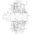
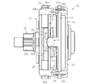
- FIG. 1 is a cross-sectional view showing an entire configuration of a clutch unit according to an embodiment of the present invention.
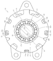
- FIG. 2 is a cross-sectional view taken along the line PP of FIG. 1;
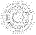
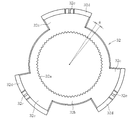
- FIG. 2 is a cross-sectional view taken along the line QQ in FIG.
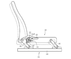
- It is a block diagram which shows the seat of a motor vehicle, and a seat lifter part.
- FIG. 6 is an exploded perspective view showing a slide gear, an elastic member and a side plate in the clutch unit of FIG. 1; It is the side view which looked at the slide gear of FIG. 5 from the input side.
- It is a top view which shows the clutch unit of FIG.
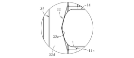
- It is an enlarged view which shows the X section of FIG.
- It is sectional drawing which shows the operation state of the clutch unit of FIG.
- FIG. 1 is a cross-sectional view showing the entire configuration of the clutch unit
- FIG. 2 is a cross-sectional view taken along the line PP in FIG. 1
- FIG. 3 is a cross-sectional view taken along the line QQ in FIG.
- the clutch unit 10 of this embodiment has a structure in which a lever side clutch portion 11 as an input side clutch portion and a brake side clutch portion 12 as an output side clutch portion are unitized.
- the lever side clutch unit 11 controls transmission and interruption of rotational torque input by lever operation.
- the brake side clutch unit 12 has a reverse input blocking function of transmitting the rotational torque from the lever side clutch unit 11 to the output side and blocking the rotational torque reversely input from the output side.
- the lever-side clutch portion 11 includes the side plate 13 and the outer ring 14, the inner ring 15, a plurality of cylindrical rollers 16, a cage 17, an inner centering spring 18, and an outer centering spring 19. And the main part is composed.
- the side plate 13 and the outer ring 14 are integrated by fitting the claws 13a formed on the outer peripheral edge of the side plate 13 into the notched concave portions 14a formed on the outer peripheral edge of the outer ring 14, and caulking The rotational torque is input by the operation.
- a plurality of cam surfaces 14 b are formed on the inner periphery of the outer ring 14 at equal intervals in the circumferential direction.
- the rotational torque is input to the outer ring 14 by an operation lever 43 (see FIG. 4) attached to the side plate 13 by screwing or the like.
- the inner ring 15 has a cylindrical portion 15a through which the output shaft 22 is inserted, an enlarged diameter portion 15b in which a brake side end of the cylindrical portion 15a extends radially outward, and an outer peripheral end of the enlarged diameter portion 15b. It consists of a plurality of column parts 15c (refer to Drawing 3) which projected by bending a part in the direction of an axis.
- the inner ring 15 transmits the rotational torque input from the outer ring 14 to the brake clutch portion 12.
- a weir 20 is formed between the cylindrical outer peripheral surface 15 d of the cylindrical portion 15 a of the inner ring 15 and the cam surface 14 b formed on the inner periphery of the outer ring 14.
- the cylindrical rollers 16 transmit and block the rotational torque from the outer ring 14 by engagement and disengagement at the wedging gap 20 formed between the cam surface 14 b of the outer ring 14 and the outer peripheral surface 15 d of the cylindrical portion 15 a of the inner ring 15. Control.
- a plurality of pockets 17 a for accommodating the cylindrical rollers 16 are formed at equal intervals in the circumferential direction.
- the cylindrical roller 16 is held at equal intervals in the circumferential direction by the cage gap 20 between the cam surface 14 b of the outer ring 14 and the outer peripheral surface 15 d of the cylindrical portion 15 a of the inner ring 15 by the cage 17.
- the inner centering spring 18 is a C-shaped elastic member having a circular cross section and disposed between the retainer 17 and the cover 24 of the brake-side clutch portion 12, and both ends thereof are a part of the retainer 17 and the cover 24. It is locked.
- the outer centering spring 19 located radially outward of the inner centering spring 18 is a C-shaped band plate elastic member disposed between the outer ring 14 and the above-mentioned cover 24, and both ends thereof are the outer ring 14 and the cover 24. It is locked to a part of
- the brake clutch portion 12 includes the inner ring 15 of the lever clutch portion 11, the output shaft 22 which is an output member, the outer ring 23 which is a stationary member, the cover 24 and the side plate 25;
- a main portion is constituted by a plurality of pairs of engaging elements, a cylindrical roller 27 and a plate spring 28 having an N-shaped cross section, and a friction ring 29.
- the output shaft 22 has a shaft portion 22a on which the cylindrical portion 15a of the inner ring 15 is extrapolated, a large diameter portion 22b integrally formed substantially at the center of the shaft portion 22a, and an output side end of the shaft portion 22a It consists of a pinion gear portion 22d coaxially formed in the portion, and the rotational torque from the lever side clutch portion 11 is output.
- the pinion gear portion 22d of the output shaft 22 is connected to the seat lifter portion 39 (see FIG. 4).
- the components of the lever side clutch unit 11 are prevented from coming off by press-fitting the washer 31 to the input side end of the shaft portion 22 a of the output shaft 22 via the wave washer 30.
- a plurality of flat cam surfaces 22 e are formed at equal intervals in the circumferential direction on the outer periphery of the large diameter portion 22 b of the output shaft 22. Between the cam surface 22e of the large diameter portion 22b and the cylindrical inner peripheral surface 23a of the outer ring 23, a wedging gap 26 is formed.
- Two cylindrical rollers 27 and one plate spring 28 interposed therebetween are disposed in the wedging gap 26 respectively.
- the cylindrical roller 27 controls the blocking of the rotational torque reversely input from the output shaft 22 and the transmission of the rotational torque input from the inner ring 15 by engagement and disengagement at the weir clearance 26.
- the leaf spring 28 biases the cylindrical rollers 27 against each other in the circumferential direction.
- the cylindrical rollers 27 and the plate springs 28 are disposed at equal intervals in the circumferential direction by the column portions 15 c of the inner ring 15 having a function of transmitting the rotational torque input from the outer ring 14 to the output shaft 22. That is, the column portion 15c of the inner ring 15 has a function of accommodating the cylindrical roller 27 and the plate spring 28 in the pocket 15f and maintaining the same in the circumferential direction.
- the large diameter portion 22 b of the output shaft 22 is provided with a projection 22 f for transmitting the rotational torque from the inner ring 15 to the output shaft 22.
- the projection 22 f is inserted and arranged in a hole 15 e formed in the enlarged diameter portion 15 b of the inner ring 15 with a clearance in the circumferential direction.
- the outer ring 23, the cover 24, and the side plate 25 are provided in the notch recess 23b formed on the outer peripheral edge of the outer ring 23, and the notch recess (not shown) formed on the outer peripheral edge of the cover 24.
- the claws 25a formed on the outer peripheral edge are integrated and integrated by fitting and caulking.
- the friction ring 29 is a member made of resin, for example, and is fixed to the side plate 25.
- the friction ring 29 is press-fitted to the inner peripheral surface 22g of the annular recess 22c formed in the large diameter portion 22b of the output shaft 22 with a fitting margin.
- a rotational resistance (sliding torque) is applied to the reference numeral 22.
- lever side clutch part 11 and the brake side clutch part 12 which comprise the above structures is demonstrated below.
- the cylindrical roller 27 separates from the weir clearance 26.
- the locked state of the output shaft 22 is released and the output shaft 22 becomes rotatable.
- the friction ring 29 applies a rotational resistance to the output shaft 22.
- FIG. 4 shows a seat 40 mounted in the passenger compartment of a motor vehicle.
- the seating surface height of the seat 40 in the seat lifter 39 is adjusted by the operation lever 43 attached to the side plate 13 (see FIG. 1) of the lever side clutch 11 in the clutch unit 10.
- the seat lifter unit 39 has the following structure.
- each of the link members 45 and 46 is pivotably connected to the slide movable member 44.
- the other ends of the link members 45 and 46 are pivotably attached to the seat 40 respectively.
- a sector gear 47 is integrally provided at the other end of the link member 45.
- the sector gear 47 meshes with the pinion gear portion 22 d of the output shaft 22 of the clutch unit 10.
- the pinion gear portion 22d of the output shaft 22 of the brake clutch portion 12 rotates clockwise (FIG. 4) by the rotational torque transmitted from the lever clutch portion 11 to the brake clutch portion 12 when the brake clutch portion 12 is unlocked. In the direction of the arrow).
- the sector gear 47 meshing with the pinion gear portion 22d pivots counterclockwise (in the direction of the arrow in FIG. 4), and the link member 45 and the link member 46 both tilt to lower the seat surface of the seat 40 become.
- the overall configuration of the clutch unit 10 in this embodiment is as described above, and its characteristic configuration will be described in detail below.
- the clutch unit 10 of this embodiment has the following structure in order to reliably lock the output shaft 22 even if the rotational torque in the forward and reverse directions as described above is continuously reversely input to the output shaft 22.
- the brake-side clutch portion 12 is a gear member that meshes with the output shaft 22 at the time of blocking the rotational torque, and is disengaged from the output shaft 22 at the time of transmitting the rotational torque.
- a structure in which the gear 32 is attached to the outer ring 23 is provided.
- the slide gear 32 is arranged to be movable in the axial direction with respect to the output shaft 22.
- the slide gear 32 has a ring-shaped main body 32b having teeth portions 32a (hereinafter referred to as internal teeth) formed on the inner periphery thereof, and a plurality of circumferential positions (3 points in FIG. 5) on the outer periphery of the ring-shaped main body 32b.
- the flange portion 32c extends radially outward at equal intervals, and the flange portion 32d axially extends from the flange portion 32c.
- the number of teeth of the internal teeth 32a of the slide gear 32 is set to 60 to 100. That is, as shown in FIG. 6, the central angle ⁇ per tooth of the internal teeth 32a of the slide gear 32 is set to 3.6 ° or more and 6 ° or less. Table 1 shows the correspondence between the number of teeth and the central angle per tooth.
- the module is set to 0.4 to 0.8 for the internal teeth 32a of the slide gear 32.
- the module is the pitch circle diameter divided by the number of teeth.
- Table 2 shows the relationship between the number of teeth and the module.
- the numerical range of the module for the internal teeth 32a of the slide gear 32 it is possible to easily secure the tooth thickness of the internal teeth 32a, and to ensure good operability and sufficient strength.
- the internal teeth 32a can be realized. Further, by defining the numerical range of the module as described above, a large torque load can be achieved, and the number of cylindrical rollers can be reduced.
- the number of teeth is 60
- the module is 0.6, 0.8
- the number of teeth is 70
- the module is 0.5, 0.6
- the number of teeth It was found that 80 modules with 0.5, 0.6, 90 teeth, 0.4, 0.5 with module, 100 teeth with 0.4 with 0.4 module are effective. .
- the central angle ⁇ per tooth is set to about 5 °, the number of teeth to 70, and the module to 0.5.
- a tooth portion 22 h (hereinafter referred to as an external tooth) corresponding to the internal tooth 32 a of the slide gear 32 is formed.
- a recess 23c corresponding to the flange portion 32c of the slide gear 32 is formed on the end face of the outer ring 23 . Furthermore, on the outer peripheral surface of the outer ring 23, a recess 23d corresponding to the flange portion 32d of the slide gear 32 is formed.
- the slide gear 32 is assembled to the outer ring 23 by housing the flange portion 32 c in the recess 23 c of the end face of the outer ring 23 and fitting the flange portion 32 d into the recess 23 d of the outer peripheral surface of the outer ring 23.
- a cam mechanism 33 for moving the slide gear 32 in the axial direction to control engagement and disengagement with the output shaft 22 is interposed between the slide gear 32 and the outer ring 14 of the lever side clutch portion 11.
- the cam mechanism 33 has a V-shaped cam groove 32 e formed on the end face of the flange portion 32 d of the slide gear 32 and an outer periphery of the outer ring 14 of the lever side clutch portion 11. It is comprised by the convex part 14c extended to direction.
- the tip bent portion of the convex portion 14 c of the outer ring 14 is in contact with the cam surface of the cam groove 32 e of the slide gear 32.
- an elastic member 34 elastically urging the slide gear 32 in the direction of meshing with the output shaft 22 between the side plate 25 of the brake clutch 12 and the slide gear 32. Intervenes.
- the elastic member 34 for example, a ring-shaped wave spring as shown in FIG.
- the outer ring 14 is maintained in the neutral state by the outer centering spring 19 in the state where the rotational torque is not input from the outer ring 14 of the lever side clutch portion 11.
- the slide gear 32 is axially pressed by the elastic force of the elastic member 34, and the internal teeth 32a of the slide gear 32 mesh with the external teeth 22h of the output shaft 22 (see FIG. 1). As a result, the output shaft 22 is locked.
- the contact position of the cylindrical roller 27 is slightly shifted between the outer ring 23 and the output shaft 22, or hysteresis of elastic deformation exists in the output shaft 22, the outer ring 23, and the cylindrical roller 27 on which the rotational torque is loaded
- the meshing between the internal teeth 32a of the slide gear 32 and the external teeth 22h of the output shaft 22 can prevent the output shaft 22 from rotating gradually. As a result, it is possible to prevent the occurrence of a phenomenon in which the seat 40 slightly drops.
- the meshing of the internal teeth 32 a of the slide gear 32 and the external teeth 22 h of the output shaft 22 enables a large capacity torque load on the brake clutch portion 12.
- the number of pairs of cylindrical rollers 27 constituting the brake-side clutch unit 12 can be reduced, and the weight and cost of the clutch unit 10 can be reduced.
- six pairs of cylindrical rollers 27 are used, but the present invention is not limited thereto.
- the present invention is not limited thereto.
- the number of teeth is 70 and the module is 0.5, the number of teeth is five, Sufficient strength can be ensured even if the number of cylindrical rollers 27 is reduced, such as 4 pairs for 60 modules and 0.6 for 70 pairs of teeth with 70 teeth and 0.6 modules. it can.
- an elastic member 34 is interposed between the side plate 25 of the brake clutch 12 and the slide gear 32 to elastically bias the slide gear 32 in the direction of meshing with the output shaft 22. doing.
- the axial movement of the slide gear 32 separates the internal teeth 32a of the slide gear 32 from the external teeth 22h of the output shaft 22, and the engagement between the internal teeth 32a of the slide gear 32 and the external teeth 22h of the output shaft 22 is released. Be done. As a result, the output shaft 22 becomes rotatable with respect to the outer ring 23.
- the engagement of the cylindrical roller 27 is the inner ring until the internal teeth 32a of the slide gear 32 completely separate from the external teeth 22h of the output shaft 22 and the output shaft 22 becomes rotatable. It is necessary to prevent release by 15.
- the cylindrical roller 27 has a gap 26 between the outer ring 23 and the output shaft 22. It also requires a structure to engage with the
Landscapes
- Engineering & Computer Science (AREA)
- General Engineering & Computer Science (AREA)
- Mechanical Engineering (AREA)
- Aviation & Aerospace Engineering (AREA)
- Transportation (AREA)
- Seats For Vehicles (AREA)
- Braking Arrangements (AREA)
Abstract
La présente invention comprend : une partie d'embrayage côté levier qui commande la transmission et le blocage d'un couple de rotation introduit par l'actionnement du levier, et une partie d'embrayage côté frein qui transmet le couple de rotation de la partie d'embrayage côté levier au côté de sortie et bloque le couple de rotation introduit inversement depuis le côté de sortie. La partie d'embrayage côté frein est pourvue d'une bague externe, dont la rotation est limitée, et d'un arbre de sortie depuis lequel la rotation est délivrée, et fixe, à la bague externe, un engrenage coulissant 32 qui vient en prise avec l'arbre de sortie tandis que le couple de rotation est bloqué, et le sépare de l'arbre de sortie lorsque le couple de rotation est transmis. L'engrenage coulissant 32 a un module de 0,4 à 0,8 et a des dents internes 32a qui sont en un nombre limité de 60 à 100.
Applications Claiming Priority (2)
| Application Number | Priority Date | Filing Date | Title |
|---|---|---|---|
| JP2017180265A JP6474871B1 (ja) | 2017-09-20 | 2017-09-20 | クラッチユニット |
| JP2017-180265 | 2017-09-20 |
Publications (1)
| Publication Number | Publication Date |
|---|---|
| WO2019059141A1 true WO2019059141A1 (fr) | 2019-03-28 |
Family
ID=65516983
Family Applications (1)
| Application Number | Title | Priority Date | Filing Date |
|---|---|---|---|
| PCT/JP2018/034308 Ceased WO2019059141A1 (fr) | 2017-09-20 | 2018-09-14 | Unité d'embrayage |
Country Status (2)
| Country | Link |
|---|---|
| JP (1) | JP6474871B1 (fr) |
| WO (1) | WO2019059141A1 (fr) |
Families Citing this family (1)
| Publication number | Priority date | Publication date | Assignee | Title |
|---|---|---|---|---|
| JP7188291B2 (ja) * | 2019-06-25 | 2022-12-13 | 豊田合成株式会社 | 作業車両用コンソールユニット |
Citations (4)
| Publication number | Priority date | Publication date | Assignee | Title |
|---|---|---|---|---|
| JP2001520605A (ja) * | 1998-02-10 | 2001-10-30 | シュヴァルツビッヒ,イェルク | シートアジャスタ |
| US8496098B1 (en) * | 2008-12-23 | 2013-07-30 | Crh North America, Inc. | Manual seat height adjuster mechanism |
| JP2013224692A (ja) * | 2012-04-20 | 2013-10-31 | Ntn Corp | クラッチユニット |
| WO2017150401A1 (fr) * | 2016-03-01 | 2017-09-08 | Ntn株式会社 | Unité d'embrayage |
-
2017
- 2017-09-20 JP JP2017180265A patent/JP6474871B1/ja active Active
-
2018
- 2018-09-14 WO PCT/JP2018/034308 patent/WO2019059141A1/fr not_active Ceased
Patent Citations (4)
| Publication number | Priority date | Publication date | Assignee | Title |
|---|---|---|---|---|
| JP2001520605A (ja) * | 1998-02-10 | 2001-10-30 | シュヴァルツビッヒ,イェルク | シートアジャスタ |
| US8496098B1 (en) * | 2008-12-23 | 2013-07-30 | Crh North America, Inc. | Manual seat height adjuster mechanism |
| JP2013224692A (ja) * | 2012-04-20 | 2013-10-31 | Ntn Corp | クラッチユニット |
| WO2017150401A1 (fr) * | 2016-03-01 | 2017-09-08 | Ntn株式会社 | Unité d'embrayage |
Also Published As
| Publication number | Publication date |
|---|---|
| JP2019056397A (ja) | 2019-04-11 |
| JP6474871B1 (ja) | 2019-02-27 |
Similar Documents
| Publication | Publication Date | Title |
|---|---|---|
| CN109642625B (zh) | 离合器单元 | |
| CN108603545B (zh) | 离合器单元 | |
| JP6636366B2 (ja) | クラッチユニット | |
| US20190210490A1 (en) | Clutch unit | |
| JP2015148332A (ja) | クラッチユニット | |
| WO2018042991A1 (fr) | Unité d'embrayage | |
| JP2019132424A (ja) | クラッチユニット | |
| WO2019059141A1 (fr) | Unité d'embrayage | |
| JP6509983B2 (ja) | クラッチユニット | |
| JP2020041665A (ja) | クラッチユニット | |
| JP2018112277A (ja) | クラッチユニット | |
| WO2019151261A1 (fr) | Unité d'embrayage | |
| JP7336907B2 (ja) | クラッチユニット | |
| WO2017150401A1 (fr) | Unité d'embrayage | |
| JP7152869B2 (ja) | クラッチユニット | |
| JP2018119647A (ja) | クラッチユニット | |
| WO2019059287A1 (fr) | Unité d'embrayage | |
| JP7110062B2 (ja) | クラッチユニット | |
| JP2019007543A (ja) | クラッチユニット | |
| WO2020059811A1 (fr) | Unité d'embrayage | |
| EP3686453A1 (fr) | Unité d'embrayage | |
| JP2021001654A (ja) | クラッチユニット | |
| JP2019044859A (ja) | クラッチユニット | |
| JP2014037868A (ja) | クラッチユニット | |
| JP2018155322A (ja) | クラッチユニット |
Legal Events
| Date | Code | Title | Description |
|---|---|---|---|
| 121 | Ep: the epo has been informed by wipo that ep was designated in this application |
Ref document number: 18858714 Country of ref document: EP Kind code of ref document: A1 |
|
| NENP | Non-entry into the national phase |
Ref country code: DE |
|
| 122 | Ep: pct application non-entry in european phase |
Ref document number: 18858714 Country of ref document: EP Kind code of ref document: A1 |