WO2019059157A1 - Embrayage de ventilateur - Google Patents
Embrayage de ventilateur Download PDFInfo
- Publication number
- WO2019059157A1 WO2019059157A1 PCT/JP2018/034385 JP2018034385W WO2019059157A1 WO 2019059157 A1 WO2019059157 A1 WO 2019059157A1 JP 2018034385 W JP2018034385 W JP 2018034385W WO 2019059157 A1 WO2019059157 A1 WO 2019059157A1
- Authority
- WO
- WIPO (PCT)
- Prior art keywords
- clutch
- oil chamber
- fan
- drive shaft
- clutch case
- Prior art date
- Legal status (The legal status is an assumption and is not a legal conclusion. Google has not performed a legal analysis and makes no representation as to the accuracy of the status listed.)
- Ceased
Links
Images


Classifications
-
- F—MECHANICAL ENGINEERING; LIGHTING; HEATING; WEAPONS; BLASTING
- F16—ENGINEERING ELEMENTS AND UNITS; GENERAL MEASURES FOR PRODUCING AND MAINTAINING EFFECTIVE FUNCTIONING OF MACHINES OR INSTALLATIONS; THERMAL INSULATION IN GENERAL
- F16D—COUPLINGS FOR TRANSMITTING ROTATION; CLUTCHES; BRAKES
- F16D35/00—Fluid clutches in which the clutching is predominantly obtained by fluid adhesion
- F16D35/02—Fluid clutches in which the clutching is predominantly obtained by fluid adhesion with rotary working chambers and rotary reservoirs, e.g. in one coupling part
Definitions
- the elastic support member and the viscous fluid flowing into the oil chamber perform the function of the attenuator, and the mass placed in the oil chamber is a mass (weight)
- the vibration transmitted from the engine can be suppressed by exhibiting the function of
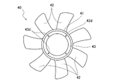
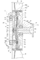
- the fan clutch 1 is a temperature-sensitive viscous coupling applied to a cooling fan of a radiator mounted on a vehicle. As shown in FIG. 1, the fan clutch 1 is rotatably supported by an input side rotation member 10 rotationally driven by the engine and a bearing 30 with respect to the input side rotation member 10, and also has an input side rotation. An output side rotation member 20 is provided to rotate by receiving rotation of the member 10 via a viscous fluid, and a fan 40 attached to the output side rotation member 20.
- the output side rotation member 20 is fixed to the first clutch case 21 rotatably supported by the drive shaft 11 and the first clutch case 21, and the drive disk 12 and the viscous fluid are interposed between the first clutch case 21 and the output side rotation member 20.
- a second clutch case 22 that forms an internal space K that accommodates the The first and second clutch cases 21 and 22 form a clutch case.
- viscous fluid is silicone oil, for example.
- the second clutch case 22 is a plate-shaped member made of an aluminum alloy that covers the drive disk 12, and the peripheral flange portion 22 a is fixed to the peripheral portion of the first clutch case 21 via a bolt B. Thereby, the first clutch case 21 and the second clutch case 22 are integrally rotatable. Further, in the second clutch case 22, the fan 40 is bolted to the peripheral flange portion 22a, and a case-side labyrinth groove 22c is formed at a position facing the disc-side labyrinth groove 12c of the inner side surface 22b.
- the second clutch case 22 and the first clutch case 21 are not limited to those made of aluminum alloy. For example, it may be formed of a metal such as magnesium, steel or copper, or a heat resistant resin such as polyphenylene sulfide resin.
- the bimetal 23 opens and closes the opening 24 c by the valve 25 according to the ambient temperature, and adjusts the flow rate of the viscous fluid returned from the oil chamber 24 b to the torque transmission chamber 24 a. Then, by adjusting the circulation amount of the viscous fluid, the torque transmitted from the drive disk 12 to the second clutch case 22 changes.
- the bimetal 23 has a strip-like flat plate shape, but a temperature sensitive spiral spring may be used.
- the elastic support member 53 is formed of foam rubber, steel wool, metal sponge, a spring, a resin or the like.
- the elastic support member 53 may be supported in contact with a part of the mass 52, as shown in FIGS. 1 and 3, or may be covered in the oil chamber 50 while covering the entire surface of the mass 52. It may be filled and hold
- FIG. 1 shows the fan clutch 1 in the cold state when the engine is stopped.
- the opening 24 c formed in the partition wall 24 is closed by the valve 25.
- the drive shaft 11 coupled to the pulley shaft is integrally rotationally driven.
- the drive disk 12 rotates with the drive shaft 11.
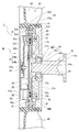
- the viscous fluid in the torque transfer chamber 24 a flows to the oil chamber 24 b through the oil circulation path 24 d by the action of the centrifugal force generated by the rotation of the drive disk 12.
- the oil chamber 50 communicating with the torque transfer chamber 24 a is formed in the first clutch case 21, and the mass 52 supported by the elastic support member 53 is formed in the oil chamber 50. It is arranged. Therefore, the amplitude energy of the vibration input to the drive shaft 11 is transmitted to the first clutch case 21 through the bearing 30, and is applied to the elastic support member 53 supporting the viscous fluid and the mass 52 in the oil chamber 50. It is stored once. And the amplitude energy stored in this viscous fluid etc. is released at the time of the reverse amplitude which vibrates in the reverse direction. That is, the viscous fluid and the elastic support member 53 in the oil chamber 50 exhibit the function of the attenuator, and the vibration of the first clutch case 21 can be suppressed.
- the mass 52 disposed in the oil chamber 50 is also formed in an arc shape extending in the circumferential direction around the drive shaft 11. Therefore, the weight can be changed without largely changing the position of the center of gravity of the first clutch case 21. Thus, the natural frequency of the first clutch case 21 can be easily adjusted, and the vibration of the first clutch case 21 can be appropriately suppressed.
- the oil chamber communicating with the internal space K via the communication passage 51 may be formed outside the first clutch case 21.
- the oil chamber 50C may be formed at the boundary position between the first clutch case 21 and the second clutch case 22. That is, concave portions facing each other are formed in both the first clutch case 21 and the second clutch case 22 to form an oil chamber 50C.
- the oil chamber 50C is formed along the outer periphery of the drive disk 12.
Landscapes
- Engineering & Computer Science (AREA)
- General Engineering & Computer Science (AREA)
- Mechanical Engineering (AREA)
- Structures Of Non-Positive Displacement Pumps (AREA)
Abstract
L'invention fournit un embrayage de ventilateur qui permet d'inhiber l'augmentation de vibrations lors de la production d'une entrée de vibrations provenant d'un moteur. Plus précisément, l'invention concerne un embrayage de ventilateur (1) qui est équipé : d'un axe d'entraînement (11) entraîné en rotation par un moteur ; d'un disque d'entraînement (12) fixé sur l'axe d'entraînement (11) ; d'un premier et d'un second carter d'embrayage (21, 22) qui sont supportés en rotation libre sur l'axe d'entraînement (11), et auxquels la rotation du disque d'entraînement (12) est transmise par l'intermédiaire d'un fluide visqueux ; et d'un ventilateur (40) installé sur le second carter d'embrayage (22). Le premier et le second carter d'embrayage (21, 22) possèdent un caisson de transmission de couple (24a) dans lequel est disposé le disque d'entraînement (12), un caisson d'huile (24b) compartimenté vis-à-vis de la chambre de transmission de couple (24a) par l'intermédiaire d'une paroi de séparation (24), et une chambre d'huile (50) communiquant avec le caisson d'huile (24b). Enfin, une masse (52) est configurée de manière à être supportée par l'intermédiaire d'un élément de support élastique, dans la partie interne de la chambre d'huile (50).
Applications Claiming Priority (2)
| Application Number | Priority Date | Filing Date | Title |
|---|---|---|---|
| JP2017-182812 | 2017-09-22 | ||
| JP2017182812A JP2019056477A (ja) | 2017-09-22 | 2017-09-22 | ファンクラッチ |
Publications (1)
| Publication Number | Publication Date |
|---|---|
| WO2019059157A1 true WO2019059157A1 (fr) | 2019-03-28 |
Family
ID=65809752
Family Applications (1)
| Application Number | Title | Priority Date | Filing Date |
|---|---|---|---|
| PCT/JP2018/034385 Ceased WO2019059157A1 (fr) | 2017-09-22 | 2018-09-18 | Embrayage de ventilateur |
Country Status (2)
| Country | Link |
|---|---|
| JP (1) | JP2019056477A (fr) |
| WO (1) | WO2019059157A1 (fr) |
Citations (6)
| Publication number | Priority date | Publication date | Assignee | Title |
|---|---|---|---|---|
| JPS5376242A (en) * | 1976-12-17 | 1978-07-06 | Isuzu Motors Ltd | Fluid coupling cotrol system for cooling fan |
| JPS547064A (en) * | 1977-06-18 | 1979-01-19 | Aisin Seiki Co Ltd | Viscous fluid coupling for driving automotive engine cooling fan |
| JPH028518A (ja) * | 1988-06-24 | 1990-01-12 | Usui Internatl Ind Co Ltd | 温度感応型流体式フアン・カツプリング装置 |
| JPH02127828U (fr) * | 1989-03-30 | 1990-10-22 | ||
| JPH0378140U (fr) * | 1989-12-01 | 1991-08-07 | ||
| US20160123408A1 (en) * | 2014-11-01 | 2016-05-05 | Borgwarner Inc. | Viscous clutch with high-speed reservoir and bimetal strip member |
-
2017
- 2017-09-22 JP JP2017182812A patent/JP2019056477A/ja active Pending
-
2018
- 2018-09-18 WO PCT/JP2018/034385 patent/WO2019059157A1/fr not_active Ceased
Patent Citations (6)
| Publication number | Priority date | Publication date | Assignee | Title |
|---|---|---|---|---|
| JPS5376242A (en) * | 1976-12-17 | 1978-07-06 | Isuzu Motors Ltd | Fluid coupling cotrol system for cooling fan |
| JPS547064A (en) * | 1977-06-18 | 1979-01-19 | Aisin Seiki Co Ltd | Viscous fluid coupling for driving automotive engine cooling fan |
| JPH028518A (ja) * | 1988-06-24 | 1990-01-12 | Usui Internatl Ind Co Ltd | 温度感応型流体式フアン・カツプリング装置 |
| JPH02127828U (fr) * | 1989-03-30 | 1990-10-22 | ||
| JPH0378140U (fr) * | 1989-12-01 | 1991-08-07 | ||
| US20160123408A1 (en) * | 2014-11-01 | 2016-05-05 | Borgwarner Inc. | Viscous clutch with high-speed reservoir and bimetal strip member |
Also Published As
| Publication number | Publication date |
|---|---|
| JP2019056477A (ja) | 2019-04-11 |
Similar Documents
| Publication | Publication Date | Title |
|---|---|---|
| US8240442B2 (en) | Lock-up device | |
| JP3457683B2 (ja) | 分割されているフライホイール | |
| RU2640938C2 (ru) | Гидродинамическая муфта | |
| US20160281830A1 (en) | Vibration damping device | |
| US2514139A (en) | Torsional vibration damper | |
| JP2005282617A (ja) | ロックアップクラッチ付きトルクコンバータ | |
| US20010025762A1 (en) | Torsional vibration damper | |
| EP3513087A1 (fr) | Amortisseur visqueux à torsion à dissipation d'énergie élevée | |
| JPS6120694B2 (fr) | ||
| CN110848325B (zh) | 扭转振动减振器 | |
| US6782983B2 (en) | Fluid torque transmission device equipped with lockup device | |
| WO2019059157A1 (fr) | Embrayage de ventilateur | |
| JP7486280B2 (ja) | ファンクラッチ | |
| JP2000074146A (ja) | 回転振動を緩衝する装置 | |
| US4313531A (en) | Viscous fluid coupling | |
| JP6952600B2 (ja) | 車両用ファン装置 | |
| WO2019059154A1 (fr) | Embrayage du ventilateur | |
| WO2019059156A1 (fr) | Embrayage de ventilateur | |
| WO2019059155A1 (fr) | Embrayage du ventilateur | |
| US7455158B2 (en) | Viscous fluid coupling device | |
| JP2013076419A (ja) | 車両用流体伝動装置 | |
| JP5306433B2 (ja) | トルク変動吸収装置 | |
| JP2007177852A (ja) | ビスカスダンパー | |
| JP2002515574A (ja) | 振動を減衰するための装置、特に振動ダンパ | |
| CN221237111U (zh) | 改进的粘性阻尼器 |
Legal Events
| Date | Code | Title | Description |
|---|---|---|---|
| 121 | Ep: the epo has been informed by wipo that ep was designated in this application |
Ref document number: 18857818 Country of ref document: EP Kind code of ref document: A1 |
|
| NENP | Non-entry into the national phase |
Ref country code: DE |
|
| 122 | Ep: pct application non-entry in european phase |
Ref document number: 18857818 Country of ref document: EP Kind code of ref document: A1 |