WO2019059341A1 - シールリング - Google Patents
シールリング Download PDFInfo
- Publication number
- WO2019059341A1 WO2019059341A1 PCT/JP2018/035013 JP2018035013W WO2019059341A1 WO 2019059341 A1 WO2019059341 A1 WO 2019059341A1 JP 2018035013 W JP2018035013 W JP 2018035013W WO 2019059341 A1 WO2019059341 A1 WO 2019059341A1
- Authority
- WO
- WIPO (PCT)
- Prior art keywords
- dynamic pressure
- seal ring
- inner peripheral
- introduction
- peripheral wall
- Prior art date
- Legal status (The legal status is an assumption and is not a legal conclusion. Google has not performed a legal analysis and makes no representation as to the accuracy of the status listed.)
- Ceased
Links
Images
























Classifications
-
- F—MECHANICAL ENGINEERING; LIGHTING; HEATING; WEAPONS; BLASTING
- F16—ENGINEERING ELEMENTS AND UNITS; GENERAL MEASURES FOR PRODUCING AND MAINTAINING EFFECTIVE FUNCTIONING OF MACHINES OR INSTALLATIONS; THERMAL INSULATION IN GENERAL
- F16J—PISTONS; CYLINDERS; SEALINGS
- F16J15/00—Sealings
- F16J15/16—Sealings between relatively-moving surfaces
- F16J15/32—Sealings between relatively-moving surfaces with elastic sealings, e.g. O-rings
- F16J15/3284—Sealings between relatively-moving surfaces with elastic sealings, e.g. O-rings characterised by their structure; Selection of materials
-
- F—MECHANICAL ENGINEERING; LIGHTING; HEATING; WEAPONS; BLASTING
- F16—ENGINEERING ELEMENTS AND UNITS; GENERAL MEASURES FOR PRODUCING AND MAINTAINING EFFECTIVE FUNCTIONING OF MACHINES OR INSTALLATIONS; THERMAL INSULATION IN GENERAL
- F16J—PISTONS; CYLINDERS; SEALINGS
- F16J15/00—Sealings
- F16J15/16—Sealings between relatively-moving surfaces
- F16J15/26—Sealings between relatively-moving surfaces with stuffing-boxes for rigid sealing rings
-
- F—MECHANICAL ENGINEERING; LIGHTING; HEATING; WEAPONS; BLASTING
- F16—ENGINEERING ELEMENTS AND UNITS; GENERAL MEASURES FOR PRODUCING AND MAINTAINING EFFECTIVE FUNCTIONING OF MACHINES OR INSTALLATIONS; THERMAL INSULATION IN GENERAL
- F16J—PISTONS; CYLINDERS; SEALINGS
- F16J15/00—Sealings
- F16J15/46—Sealings with packing ring expanded or pressed into place by fluid pressure, e.g. inflatable packings
- F16J15/48—Sealings with packing ring expanded or pressed into place by fluid pressure, e.g. inflatable packings influenced by the pressure within the member to be sealed
-
- F—MECHANICAL ENGINEERING; LIGHTING; HEATING; WEAPONS; BLASTING
- F16—ENGINEERING ELEMENTS AND UNITS; GENERAL MEASURES FOR PRODUCING AND MAINTAINING EFFECTIVE FUNCTIONING OF MACHINES OR INSTALLATIONS; THERMAL INSULATION IN GENERAL
- F16J—PISTONS; CYLINDERS; SEALINGS
- F16J15/00—Sealings
- F16J15/16—Sealings between relatively-moving surfaces
- F16J15/164—Sealings between relatively-moving surfaces the sealing action depending on movements; pressure difference, temperature or presence of leaking fluid
-
- F—MECHANICAL ENGINEERING; LIGHTING; HEATING; WEAPONS; BLASTING
- F16—ENGINEERING ELEMENTS AND UNITS; GENERAL MEASURES FOR PRODUCING AND MAINTAINING EFFECTIVE FUNCTIONING OF MACHINES OR INSTALLATIONS; THERMAL INSULATION IN GENERAL
- F16J—PISTONS; CYLINDERS; SEALINGS
- F16J15/00—Sealings
- F16J15/16—Sealings between relatively-moving surfaces
- F16J15/18—Sealings between relatively-moving surfaces with stuffing-boxes for elastic or plastic packings
- F16J15/182—Sealings between relatively-moving surfaces with stuffing-boxes for elastic or plastic packings with lubricating, cooling or draining means
-
- F—MECHANICAL ENGINEERING; LIGHTING; HEATING; WEAPONS; BLASTING
- F16—ENGINEERING ELEMENTS AND UNITS; GENERAL MEASURES FOR PRODUCING AND MAINTAINING EFFECTIVE FUNCTIONING OF MACHINES OR INSTALLATIONS; THERMAL INSULATION IN GENERAL
- F16J—PISTONS; CYLINDERS; SEALINGS
- F16J15/00—Sealings
- F16J15/16—Sealings between relatively-moving surfaces
- F16J15/32—Sealings between relatively-moving surfaces with elastic sealings, e.g. O-rings
- F16J15/3244—Sealings between relatively-moving surfaces with elastic sealings, e.g. O-rings with hydrodynamic pumping action
-
- F—MECHANICAL ENGINEERING; LIGHTING; HEATING; WEAPONS; BLASTING
- F16—ENGINEERING ELEMENTS AND UNITS; GENERAL MEASURES FOR PRODUCING AND MAINTAINING EFFECTIVE FUNCTIONING OF MACHINES OR INSTALLATIONS; THERMAL INSULATION IN GENERAL
- F16J—PISTONS; CYLINDERS; SEALINGS
- F16J15/00—Sealings
- F16J15/16—Sealings between relatively-moving surfaces
- F16J15/32—Sealings between relatively-moving surfaces with elastic sealings, e.g. O-rings
- F16J15/3268—Mounting of sealing rings
- F16J15/3272—Mounting of sealing rings the rings having a break or opening, e.g. to enable mounting on a shaft otherwise than from a shaft end
-
- F—MECHANICAL ENGINEERING; LIGHTING; HEATING; WEAPONS; BLASTING
- F16—ENGINEERING ELEMENTS AND UNITS; GENERAL MEASURES FOR PRODUCING AND MAINTAINING EFFECTIVE FUNCTIONING OF MACHINES OR INSTALLATIONS; THERMAL INSULATION IN GENERAL
- F16J—PISTONS; CYLINDERS; SEALINGS
- F16J15/00—Sealings
- F16J15/44—Free-space packings
- F16J15/441—Free-space packings with floating ring
Definitions
- the present invention relates to a seal ring for sealing a shaft and a shaft hole into which the shaft is inserted.
- sealing devices are conventionally used to prevent leakage of hydraulic oil used for hydraulic control.
- a sealing ring which is used to seal between the shaft and the axial hole into which this shaft is inserted.
- the seal ring is attached to a groove formed on the outer peripheral surface of the shaft and contacts the side surface of the groove and the inner peripheral surface of the shaft hole to seal the space between the shaft and the shaft hole And hold the oil pressure of the hydraulic oil between the shaft and the shaft hole.
- This invention is made in view of the above-mentioned subject, and the purpose provides the seal ring which can aim at reduction of the further sliding resistance, or aims at the reduction of the further sliding resistance, and is durable.
- An object of the present invention is to provide a seal ring which can be improved in the property.
- the seal ring according to the present invention is a seal ring for sealing an annular gap between a shaft and a shaft hole into which the shaft is inserted, and is annular around an axis. And at least one side surface that faces the axial direction, a plurality of recesses formed in the side surfaces in the circumferential direction so as to be separated from one another, and a plurality of interiors formed corresponding to the plurality of recesses, respectively.
- a circumferential wall portion is provided, and the recessed portion is an introduction that opens the dynamic pressure portion extending in the circumferential direction converging on the side surface and the dynamic pressure portion extending inwardly from the dynamic pressure portion to the inner peripheral side
- the inner circumferential wall is provided one or two for each of the recesses, and each of the inner circumferential walls is associated with the dynamic pressure portion of the corresponding recess and the inner circumferential wall.
- a portion defined on the inner peripheral side of the corresponding recess by the introduction portion The inner peripheral wall surface is a surface continuing from the side surface, and the inner peripheral wall surface is inclined toward the side surface so as to sink from the side surface and extends in the circumferential direction toward the introduction portion. I assume.
- the inner peripheral wall surface is formed of at least one plane.
- the inner peripheral wall surface is a curved surface.
- the dynamic pressure portion has a bottom surface that is a surface facing the side facing the side surface, and the bottom surface is an introduction surface connected to the introduction portion;
- the dynamic pressure surface includes one or two dynamic pressure surfaces extending between the introduction surface and the side surface, and the dynamic pressure surface is circumferentially inclined to the side surface so as to rise from the introduction surface. It extends towards.
- the dynamic pressure surface is more inclined to the side surface than the inner peripheral wall surface.
- the seal ring according to the present invention is a seal ring for sealing an annular gap between a shaft and a shaft hole into which the shaft is inserted, and is annular around an axis. And at least one side surface which is a surface facing in the axial direction, a plurality of recesses formed on the side surfaces in the circumferential direction so as to be separated from one another, and a plurality of inner circumferential walls respectively formed corresponding to the plurality of recesses And the recess includes a dynamic pressure unit extending in a circumferential direction so as to converge on the side surface, and extending from the dynamic pressure unit toward the inner peripheral side to open the dynamic pressure unit toward the inner peripheral side.
- the inner peripheral wall portion is provided one or two for each of the recessed portions, and each of the inner peripheral wall portions is provided with the dynamic pressure portion of the corresponding recessed portion A portion defined on the inner peripheral side of the corresponding recess by the introduction portion
- the inner peripheral wall surface is a surface continuing from the side surface, and the inner peripheral wall surface sinks by a predetermined depth from the side surface, and is circumferentially parallel to the side surface in the lead-in portion It is characterized by extending toward.
- the inner peripheral wall surface is a flat surface sunk from the side surface by a predetermined depth via a vertical surface.
- the inner peripheral wall surface is a curved surface.
- the dynamic pressure portion has a bottom surface that is a surface facing the side facing the side surface, and the bottom surface is an introduction surface connected to the introduction portion;
- the dynamic pressure surface includes one or two dynamic pressure surfaces extending between the introduction surface and the side surface, and the dynamic pressure surface is inclined to the side surface in a circumferential direction toward the side surface so as to rise from the introduction surface. It extends towards.
- the seal ring according to the present invention is a seal ring for sealing an annular gap between a shaft and a shaft hole into which the shaft is inserted, and is annular around an axis. And at least one side surface which is a surface facing in the axial direction, a plurality of recesses formed on the side surfaces in the circumferential direction so as to be separated from one another, and a plurality of inner circumferential walls respectively formed corresponding to the plurality of recesses And the recess includes a dynamic pressure unit extending in a circumferential direction so as to converge on the side surface, and extending from the dynamic pressure unit toward the inner peripheral side to open the dynamic pressure unit toward the inner peripheral side.
- the inner peripheral wall portion is provided one or two for each of the recessed portions, and each of the inner peripheral wall portions is provided with the dynamic pressure portion of the corresponding recessed portion A portion defined on the inner peripheral side of the corresponding recess by the introduction portion It has an inner peripheral wall surface which is a surface continuing from the side surface, and the inner peripheral wall surface extends toward the introduction portion circumferentially in a step-like manner in which the predetermined peripheral depth sinks stepwise from the side surface. It is characterized by
- the lowest part in the step shape is higher than the dynamic pressure surface of the dynamic pressure portion.
- the dynamic pressure portion has a bottom surface that is a surface facing the side facing the side surface, and the bottom surface is an introduction surface connected to the introduction portion;
- the dynamic pressure surface includes one or two dynamic pressure surfaces extending between the introduction surface and the side surface, and the dynamic pressure surface is inclined to the side surface in a circumferential direction toward the side surface so as to rise from the introduction surface. It extends towards.
- the seal ring according to the present invention is a seal ring for sealing an annular gap between a shaft and a shaft hole into which the shaft is inserted, and is annular around an axis.
- Side faces which are the surfaces facing the axial direction, a plurality of dynamic pressure parts which are formed apart from each other in the circumferential direction on the side faces, and the side faces which are formed on the inner peripheral side of the side faces
- An inner peripheral wall portion which is an annular portion which protrudes on the side from the side surface, and an outer peripheral wall portion which is formed on the outer peripheral side of the side surface and which is an annular portion which protrudes on the side facing the side surface.
- the dynamic pressure portion is a recess extending in the circumferential direction that converges to the side surface, and the inner peripheral wall portion is formed on an inner peripheral wall surface that is a surface facing the axial direction, and the inner peripheral wall surface Concave that opens the above-mentioned dynamic pressure portion extending between the outer periphery and the inner Has an inlet portion at the outer peripheral wall, characterized in that it has an outer peripheral wall surface which is a surface facing in the axial direction.
- the outer peripheral wall surface extends along a plane orthogonal to the axis.
- the inner peripheral wall surface extends along a plane orthogonal to the axis.
- the inner peripheral wall surface and the outer peripheral wall surface are located at the same position in the axis x direction.
- the outer peripheral wall surface protrudes more than the inner peripheral wall surface on the side facing the side surface.
- the dynamic pressure portion has a bottom surface that is a surface facing the side facing the side surface, and the bottom surface is an introduction surface connected to the introduction portion;
- the dynamic pressure surface includes one or two dynamic pressure surfaces extending between the introduction surface and the side surface, and the dynamic pressure surface is circumferentially inclined to the side surface so as to rise from the introduction surface. It extends towards.
- the seal ring according to the present invention is a seal ring for sealing an annular gap between a shaft and a shaft hole into which the shaft is inserted, and is annular around an axis. And at least one side surface which is a surface facing in the axial direction, and a plurality of recesses formed in the side surface so as to be separated from each other in the circumferential direction, the recess being in the circumferential direction converging on the side surface It has the dynamic pressure part which extends, and the introduction part which opens the dynamic pressure part which extends from the dynamic pressure part to the inner peripheral side to the inner peripheral side, and the concave parts adjacent to each other in the plurality of concave parts It has a communicating groove which connects the above and the above-mentioned crevice.
- the communication groove communicates the dynamic pressure portion of the recess adjacent to each other with the dynamic pressure portion of the recess.
- the communication groove communicates the dynamic pressure portion of the recess adjacent to each other with the introduction portion of the recess.
- the communication groove is a slit having a predetermined depth which is recessed inward from the side surface.
- the dynamic pressure portion has a bottom surface that is a surface facing the side facing the side surface, and the bottom surface is an introduction surface connected to the introduction portion;
- the dynamic pressure surface includes one or two dynamic pressure surfaces extending between the introduction surface and the side surface, and the dynamic pressure surface is circumferentially inclined to the side surface so as to rise from the introduction surface. It extends towards.
- the seal ring according to the present invention is a seal ring for sealing an annular gap between a shaft and a shaft hole into which the shaft is inserted, and is annular around an axis. And at least one side surface that faces the axial direction, a plurality of recesses formed in the side surfaces in the circumferential direction so as to be separated from one another, and a plurality of interiors formed corresponding to the plurality of recesses, respectively.
- a circumferential wall portion is provided, and the recessed portion is an introduction that opens the dynamic pressure portion extending in the circumferential direction converging on the side surface and the dynamic pressure portion extending inwardly from the dynamic pressure portion to the inner peripheral side
- the inner circumferential wall is provided one or two for each of the recesses, and each of the inner circumferential walls is associated with the dynamic pressure portion of the corresponding recess and the inner circumferential wall.
- a portion defined on the inner peripheral side of the corresponding recess by the introduction portion Has an inner peripheral wall surface is a surface continued from the side, the said inner wall surface, wherein at least one recess formed apart from each other in the circumferential direction is formed.
- the recess extends from the outer peripheral side to the middle between the outer peripheral side and the inner peripheral side of the inner peripheral wall surface.
- the recess extends over the entire width between the outer peripheral side and the inner peripheral side of the inner peripheral wall surface.
- the recessed portion is formed midway between the outer peripheral side and the inner peripheral side of the inner peripheral wall surface.
- the inner peripheral wall surface is flush with the side surface.
- the dynamic pressure portion has a bottom surface that is a surface facing the side facing the side surface, and the bottom surface is an introduction surface connected to the introduction portion;
- the dynamic pressure surface includes one or two dynamic pressure surfaces extending between the introduction surface and the side surface, and the dynamic pressure surface is circumferentially inclined to the side surface so as to rise from the introduction surface. It extends towards.
- the introduction portion is connected to the hydrodynamic portion between circumferential ends of the hydrodynamic portion.
- the introduction portion is connected to the dynamic pressure portion at one end in a circumferential direction of the dynamic pressure portion.
- the sliding resistance can be further reduced or the sliding resistance can be further reduced to improve the durability.
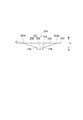
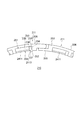
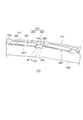
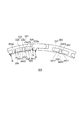
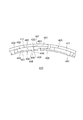
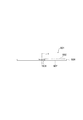
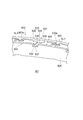
- FIG. 1 is a partially enlarged perspective view showing a schematic configuration of a seal ring according to a first embodiment of the present invention. It is the elements on larger scale of the seal ring shown in FIG.
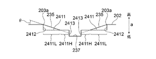
- FIG. 6 is a partial enlarged cross-sectional view taken along the line AA in FIG. 5; FIG.
- FIG. 6 is a partially enlarged cross-sectional view of the cross section BB in FIG. 5;
- FIG. 6 is a partially enlarged cross-sectional view of the BB cross section in FIG. 5 for showing a modification of the inner peripheral wall surface.
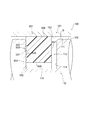
- a seal ring according to a first embodiment of the present invention is mounted on a housing of a hydraulic device to be attached and a shaft inserted in an axial hole which is a through hole formed in the housing. It is a partial expanded sectional view.
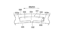
- FIG. 10 is a partially enlarged side view showing a part of a side surface of one side of a seal ring showing a schematic configuration of a seal ring according to a second embodiment of the present invention.
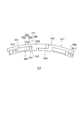
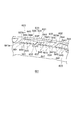
- FIG. 1 It is a partially expanded perspective view which shows schematic structure of the seal ring which concerns on the 2nd Embodiment of this invention. It is a side view of one side showing a schematic configuration of a seal ring according to a third embodiment of the present invention. It is a front view which shows schematic structure of the seal ring which concerns on the 3rd Embodiment of this invention. It is a side view of the other side which shows schematic structure of the seal ring which concerns on the 3rd Embodiment of this invention. It is a partially expanded perspective view which shows schematic structure of the seal ring which concerns on the 3rd Embodiment of this invention. It is the elements on larger scale of the seal ring shown in FIG. FIG.
- a seal ring according to a third embodiment of the present invention is mounted on a housing of a hydraulic device to be attached and a shaft inserted in an axial hole which is a through hole formed in the housing. It is a partial expanded sectional view. It is a partial enlarged side view which expands and shows a part of side of one side of a seal ring which shows a schematic structure of a seal ring concerning a 4th embodiment of the present invention.
- FIG. 1 It is a partially expanded perspective view which shows schematic structure of the seal ring which concerns on the 4th Embodiment of this invention. It is a side view of the one side which shows schematic structure of the seal ring which concerns on the 5th Embodiment of this invention. It is a front view which shows schematic structure of the seal ring which concerns on the 5th Embodiment of this invention. It is a side view of the other side which shows schematic structure of the seal ring which concerns on the 5th Embodiment of this invention. It is a partially expanded perspective view which shows schematic structure of the seal ring which concerns on the 5th Embodiment of this invention. It is the elements on larger scale of the seal ring shown in FIG. FIG.
- FIG. 28 is a partially enlarged cross-sectional view taken along the line AA in FIG.
- FIG. 28 is a partially enlarged cross-sectional view taken along line BB in FIG. 27.
- FIG. 28 is a partially enlarged cross-sectional view of the BB cross section in FIG. 27 for showing a modification of the inner peripheral wall surface.
- a seal ring according to a fifth embodiment of the present invention mounted in a housing inserted into an axial hole which is a housing of a hydraulic device to be attached and a through hole formed in the housing. It is a partial expanded sectional view.
- 16 is a partial enlarged side view showing a part of a side surface of one side of a seal ring showing a schematic configuration of a seal ring according to a sixth embodiment of the present invention. It is a partially expanded perspective view which shows schematic structure of the seal ring which concerns on the 6th Embodiment of this invention. It is a side view of the one side which shows schematic structure of the seal ring which concerns on the 7th Embodiment of this invention. It is a front view which shows schematic structure of the seal ring which concerns on the 7th Embodiment of this invention. It is a side view of the other side which shows schematic structure of the seal ring which concerns on the 7th Embodiment of this invention.
- FIG. 39 is a partial enlarged cross sectional view taken along the line AA in FIG. 38.
- FIG. 39 is a cross sectional view taken along the line BB in FIG. 38.
- a seal ring according to a seventh embodiment of the present invention is mounted on a housing of a hydraulic device to be attached and a shaft inserted in an axial hole which is a through hole formed in the housing, in use. It is a partial expanded sectional view.
- FIG. 21 is a partial enlarged side view showing a part of a side surface of one side of a seal ring showing a schematic configuration of a seal ring according to an eighth embodiment of the present invention.
- FIG. 21 is a partially enlarged perspective view showing a schematic configuration of a seal ring according to an eighth embodiment of the present invention. It is a side view of one side showing a schematic configuration of a seal ring according to a ninth embodiment of the present invention. It is a front view showing a schematic structure of a seal ring concerning a 9th embodiment of the present invention. It is a side view of the other side which shows schematic structure of the seal ring which concerns on the 9th Embodiment of this invention.
- FIG. 49 is a partial enlarged cross sectional view taken along the line AA in FIG. 48.
- a seal ring according to a ninth embodiment of the present invention is mounted on a housing of a hydraulic device to be mounted and a shaft inserted into an axial hole which is a through hole formed in the housing, in use. It is a partial expanded sectional view. It is the elements on larger scale which show the structure of the conventional seal ring. It is the elements on larger scale used for description of the effect by the slit of the seal ring of this invention.
- FIG. 49 is a partial enlarged cross sectional view taken along the line AA in FIG. 48.
- a seal ring according to a ninth embodiment of the present invention is mounted on a housing of a hydraulic device to be mounted and a shaft inserted into an axial hole which is a through hole formed in the housing, in use. It is a partial expanded sectional view. It is the elements on larger scale which show the structure of the conventional seal ring. It is the elements on larger scale used for description of
- FIG. 21 is a partial enlarged side view showing a part of a side surface of one side of a seal ring showing a schematic configuration of a seal ring according to a tenth embodiment of the present invention.
- FIG. 21 is a partially enlarged perspective view showing a schematic configuration of a seal ring according to a tenth embodiment of the present invention. It is a side view of the one side which shows schematic structure of the seal ring which concerns on the 11th Embodiment of this invention. It is a front view showing a schematic structure of a seal ring concerning an 11th embodiment of the present invention. It is a side view of the other side which shows schematic structure of the seal ring which concerns on the 11th Embodiment of this invention.
- FIG. 60 is a partial enlarged cross sectional view taken along the line AA in FIG. 59.
- FIG. 60 is a partial enlarged cross sectional view taken along line BB in FIG. 59.
- a seal ring according to an eleventh embodiment of the present invention attached to a housing of a hydraulic device to be attached and a shaft inserted into an axial hole which is a through hole formed in the housing. It is a partial expanded sectional view.
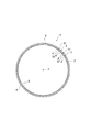
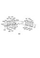
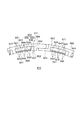
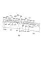
- FIG. 1 is a side view showing one side of a schematic configuration of a seal ring 1 according to a first embodiment of the present invention
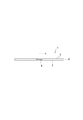
- FIG. 2 is a front view showing a schematic configuration of the seal ring 1.
- 3 is a side view of the other side showing a schematic configuration of the seal ring 1;
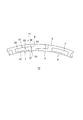
- 4 is a partially enlarged perspective view showing a schematic configuration of the seal ring 1. As shown in FIG.
- the seal ring 1 is a sealing device for sealing an annular gap between a shaft and a shaft hole into which the shaft is inserted, and in a vehicle or a general-purpose machine, the shafts rotate relative to each other. And the shaft hole formed in the housing or the like is used to seal between the shaft holes into which the shaft is inserted.
- the seal ring 1 is used by being attached to a groove formed on an outer peripheral surface of a shaft in order to hold the hydraulic pressure of hydraulic fluid.
- the target to which the seal ring 1 according to the embodiment of the present invention is applied is not limited to the above.
- the seal ring 1 is annular around the axis x, and at least one side 2 which is a surface facing in the direction of the axis x, and a plurality of the side 2 are circumferentially separated from each other And a plurality of inner peripheral wall portions 4 respectively formed corresponding to the plurality of concave portions 3.
- the recessed portion 3 has a dynamic pressure portion 31 extending in the circumferential direction converging on the side surface 2 and an introduction portion 32 opening the dynamic pressure portion 31 extending from the dynamic pressure portion 31 toward the inner peripheral side to the inner peripheral side There is.
- One or two inner circumferential wall portions 4 are provided for each of the concave portions 3, and each of the inner circumferential wall portions 4 is a corresponding concave portion by the dynamic pressure portion 31 and the introduction portion 32 of the corresponding concave portion 3.
- An inner peripheral wall surface 41 which is a portion defined on the inner peripheral side of 3 and continues from the side surface 2 is provided. The inner peripheral wall surface 41 is inclined to the side surface 2 so as to sink from the side surface 2 and extends in the circumferential direction toward the introducing portion 32.
- the side surface 2 is a side surface formed as a sliding surface pressed against the groove side surface of the groove formed on the shaft in the use state described later, and the seal ring 1 according to the present embodiment is shown in FIG. As shown in 3 and 3, only one side surface 2 as a sliding surface is provided.
- the seal ring 1 may have two side surfaces 2 as sliding surfaces, that is, the other side surface may also have side surfaces 2 as sliding surfaces. In this case, the mounting direction of the seal ring 1 with respect to the groove formed in the shaft disappears, and the mounting of the seal ring 1 becomes easy.
- the seal ring 1 has a rectangular or substantially rectangular cross section along the axis x, and the inner peripheral surface 5, which is a surface facing the inner peripheral side, and the outer peripheral side And a side surface 7 which is the other side surface.
- the inner peripheral surface 5 is, for example, a cylindrical surface or a substantially cylindrical surface centering or substantially centered on the axis x
- the outer peripheral surface 6 is a surface facing the inner peripheral surface 5, for example, the center x or It is a cylindrical surface or a substantially cylindrical surface that is substantially centered.
- the side surface 2 is an annular surface extending along or substantially perpendicular to or substantially perpendicular to the axis x, and extends between the inner peripheral surface 5 and the outer peripheral surface 6. It is a facing surface, and is an annular surface along or a plane substantially perpendicular to or substantially perpendicular to the axis x, and extends between the inner circumferential surface 5 and the outer circumferential surface 6.
- the plurality of recesses 3 are formed on the side surface 2 which is the sliding surface, and the recesses 3 are formed at equal angular intervals or substantially equal angular intervals around the axis x.
- the recess 3 is a recess that is recessed from the side surface 2 to the side surface 7 and is substantially T-shaped when viewed in the direction of the axis x.
- the concave portion 3 is provided on the inner peripheral surface 5 side in the side surface 2 so as not to protrude to the outer peripheral side than the side surface of the groove of the shaft in the use state.
- the dynamic pressure portion 31 of the recess 3 is radially separated from the outer circumferential surface 6 and the inner circumferential surface 5 and is arc-shaped with the axis x as a center or substantially center Or it extends in the circumferential direction in a substantially arc shape.
- the dynamic pressure portion 31 is provided on the inner circumferential surface 5 side in the radial direction.
- the dynamic pressure portion 31 has a bottom surface 33 which is a surface facing the side on which the side surface 2 faces, and the bottom surface 33 has an introduction surface 34 connected to the introduction portion 32, and an introduction surface 34 It has one or two dynamic pressure surfaces 35 extending between it and the side surface 2.
- the bottom surface 33 has two dynamic pressure surfaces 35.
- the introduction surface 34 is located at the lowest side in the dynamic pressure unit 31, is a flat surface or a substantially flat surface, and extends in a rectangular shape or a substantially rectangular shape.
- the axis x direction is also referred to as the height direction, and in the height direction (the direction of the arrow a in FIGS. 6 and 7), the inside of the seal ring 1 is the low side and the side 2 is the high side.
- the introduction surface 34 may be a curved surface, and may not extend in a rectangular shape.
- the dynamic pressure surface 35 is inclined to the side surface 2 so as to ascend from the introduction surface 34 and extends in the circumferential direction toward the side surface 2, is flat or substantially flat, and extends in a rectangular shape or a substantially rectangular shape .
- the dynamic pressure surface 35 extends between the introduction surface 34 and the side surface 2 and is smoothly connected to the side surface 2.
- the dynamic pressure surface 35 may be a curved surface, and may not extend in a rectangular shape.
- the dynamic pressure surface 35 may have a trapezoidal shape that widens or narrows toward the side surface 2 side.
- the dynamic pressure surface 35 is connected to the introduction surface 34 via a step surface 36 that forms a step that sinks to the side surface 7 side in the axis x direction.
- the recess 3 may not have the step surface 36, and the dynamic pressure surface 35 may be directly connected to the introduction surface 34.
- the two dynamic pressure surfaces 35 are formed in the recess 3 as described above, and the dynamic pressure surfaces 35 are circumferentially symmetrical in the bottom surface 33 with respect to the introduction surface 34. That is, one dynamic pressure surface 35 extends from one end in the circumferential direction of the introduction surface 34 in one direction in the circumferential direction to the side surface 2, and the other dynamic pressure surface 35 is the other in the circumferential direction of the introduction surface 34. Extends to the side surface 2 in the other direction in the circumferential direction from the end of the.
- the dynamic pressure portion 31 is formed so as not to protrude from the side surface of the groove of the contacting shaft in the use state described later.
- the introductory portion 32 of the concave portion 3 has a notch opened to the side surface 2 side in the inner circumferential surface 5, and the introductory portion 32 is an end in the circumferential direction of the hydrodynamic portion 31 It connects with the dynamic pressure part 31 between the parts (end part 3a).
- the introduction portion 32 is connected to the introduction surface 34 and the step surface 36 of the dynamic pressure portion 31 and has a bottom surface 37 connected to the introduction surface 34.
- the bottom surface 37 is smoothly connected to the introduction surface 34 of the dynamic pressure section 31, and the bottom surface 37 is a surface located at the same height as the introduction surface 34, for example.
- a passage communicating with the dynamic pressure portion 31 from the inner circumferential surface 5 is formed in the seal ring 1 by the introduction portion 32.
- the recess 3 communicates with the space in contact with the inner peripheral surface 5. More specifically, the dynamic pressure portion 31 is introduced It communicates with the space in contact with the inner circumferential surface 5 via the portion 32. And, in use, the dynamic pressure portion 31 forms a space extending in the circumferential direction between the shaft and the side surface of the groove, and the dynamic pressure surface 35 extends in the circumferential direction between the shaft and the side surface of the groove. A space is formed in which the height (width in the height direction) gradually decreases from the 34 side to the side 2 side.
- the inner circumferential wall portion 4 is a portion defined by a circumferential direction portion where one dynamic pressure surface 35 of the dynamic pressure portion 31 extends, the introduction portion 32 and the inner circumferential surface 5, and the dynamic pressure surface of the dynamic pressure portion 31 Adjacent to the inner circumferential side 35, it protrudes higher than the dynamic pressure surface 35.
- the inner circumferential wall portion 4 has an inner circumferential wall surface 41 and an end face 42 which is a surface extending along an axis x formed by the introduction portion 32.
- the inner peripheral wall surface 41 of the inner peripheral wall portion 4 faces the side on which the side surface 2 faces, and extends in the same or substantially the same range as the dynamic pressure surface 35 in the circumferential direction.
- inner circumferential wall surface 41 extends from the same position as step surface 36 of dynamic pressure portion 31 to the same position as end 3 a of dynamic pressure portion 31 in the circumferential direction, or the step surface 36 of dynamic pressure portion 31. It extends to the vicinity of the end 3a of the dynamic pressure section 31 from the same position. That is, the end 41a which is a portion connected to the side surface 2 of the inner peripheral wall surface 41 may be the same as the end 3a which is a portion where the dynamic pressure surface 35 is connected to the side 2 in the circumferential direction.
- the end 41a and the end 3a are at the same position in the circumferential direction. Further, when the end 41 a is in the vicinity of the end 3 a in the circumferential direction, the end 41 a of the inner peripheral wall surface 41 is on the introduction portion 32 side (inner side) than the end 3 a of the dynamic pressure surface 35 in the circumferential direction. Is preferred.
- the inner circumferential wall surface 41 is inclined to the side surface 2 and extends in the circumferential direction toward the side surface 2 so as to rise from the portion connected with the end surface 42. It is connected smoothly.
- the inner peripheral wall surface 41 is a flat surface or a substantially flat surface, and extends in a rectangular shape or a substantially rectangular shape.
- the inner circumferential wall surface 41 may be a curved surface, and may not extend in a rectangular shape.
- the inner circumferential wall surface 41 may have a trapezoidal shape that widens or narrows toward the side surface 2 side.
- the inner circumferential wall surface 41 may be formed by connecting a flat surface or a substantially flat surface in which the inclination angle with respect to the side surface 2 gradually increases.
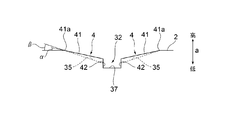
- the inclination angle ⁇ of the inner peripheral wall surface 41 to the side surface 2 is smaller than the inclination angle ⁇ (see FIG. 6) of the dynamic pressure surface 35 to the side surface 2 (see FIGS. 6 and 7).
- two inner peripheral wall portions 4 are formed for each recess 3, and the inner peripheral wall portions 4 are formed symmetrically in the circumferential direction with respect to the introduction portion 32. That is, one inner circumferential wall portion 4 extends from one end in the circumferential direction of the introducing portion 32 to the side surface 2 in one direction in the circumferential direction, and the other inner circumferential wall portion 4 extends in the circumferential direction of the introducing portion 32 Extends from the other end in the circumferential direction to the side surface 2 in the other direction in the circumferential direction.
- the inner peripheral wall surface 41 of the inner peripheral wall portion 4 faces the side surface of the groove of the shaft.
- the inner peripheral wall surface 41 is inclined with respect to the side surface 2, so that the inner peripheral wall surface 41 does not contact the side surface of the groove and forms a space between the side surface of the groove. This space is wedge-shaped, and its height gradually decreases from the end face 42 to the end 41 a.
- the seal ring 1 is formed of a resin material such as polyetheretherketone (PEEK), polyphenylene sulfide (PPS), polytetrafluoroethylene (PTFE) or the like.
- PEEK polyetheretherketone
- PPS polyphenylene sulfide
- PTFE polytetrafluoroethylene
- the circumferential length of the outer circumferential surface 6 of the seal ring 1 is shorter than the circumferential length of the inner circumferential surface of the axial hole through which the shaft is inserted, and no interference is given to the axial hole. For this reason, in a state where fluid pressure does not act on the seal ring 1 in the use state, the outer peripheral surface 6 of the seal ring 1 is in a state of being separated from the inner peripheral surface of the shaft hole.
- the seal ring 1 is not endless, and as shown in FIGS. 1 to 3, the abutment portion 8 is provided at one place in the circumferential direction.
- the joint portion 8 has a known structure that can maintain stable sealing performance even if the circumferential length of the seal ring 1 changes due to thermal expansion or thermal contraction of the seal ring 1.
- a low elasticity material PTFE or the like
- the seal ring 1 may be endless without providing the joint 8 in the seal ring 1.
- FIG. 9 shows a seal ring 1 mounted on a housing 101 of a hydraulic device 100 to be mounted and a shaft 110 inserted in an axial hole 102 which is a through hole formed in the housing 101. It is a partial expanded sectional view.
- the shaft 110 is rotatable relative to the housing 101, and an annular groove 112 recessed toward the center is formed on the outer peripheral surface 111 of the shaft 110.
- the groove 112 has a rectangular or substantially rectangular cross-sectional shape, and is defined by flat side surfaces 113 and 114 and a bottom surface 115.
- an annular space is formed between the inner peripheral surface 103 of the shaft hole 102 and the outer peripheral surface 111 of the shaft 110, and the shaft 110 and the housing 101 are filled with hydraulic oil not shown.
- a hydraulic path is formed.
- the seal ring 1 is attached to the groove 112 to seal the gap G between the shaft 110 and the shaft hole 102 in order to prevent loss of hydraulic pressure of the hydraulic fluid in the hydraulic path.
- the right side of the groove 112 is a hydraulic path
- the side surface 113 on the left side of the groove 112 is a sliding side surface pressed against the seal ring 1
- the right side of the groove 112 is high pressure
- the left side of the groove 112 is low pressure. It becomes.
- the seal ring 1 is attached to the groove 112 such that the side surface 2 faces the sliding side surface 113 of the groove 112.
- the hydraulic oil enters the recess 3 from the introduction portion 32 of the seal ring 1, and the hydraulic oil is guided to the dynamic pressure portion 31, and the hydraulic pressure ends the dynamic pressure portion 31 circumferentially along the dynamic pressure surface 35.
- section 3a Although the side surface 2 of the seal ring 1 and the sliding side surface 113 of the groove 112 are in contact with each other, the pressure of the end 3 a side of the dynamic pressure portion 31 is increased by the movement of the hydraulic oil in the dynamic pressure portion 31.
- the pressure of the hydraulic fluid on the end 3a side increases to a size that separates the side surface 2 of the seal ring 1 from the sliding side surface 113, and the hydraulic fluid leaks from the end 3a of the dynamic pressure portion 31 to the side surface 2.
- the inner peripheral wall surface 41 of the inner peripheral wall portion 4 is inclined with respect to the side surface 2, and a wedge-shaped space which narrows in the moving direction of the hydraulic oil in the dynamic pressure portion 31 with the sliding side surface 113 of the groove 112 Form. Therefore, the inner peripheral wall surface 41 can obtain the dynamic pressure effect by the hydraulic oil similarly to the dynamic pressure effect of the recess 3 described above, and the inner peripheral wall surface 41 also reduces the sliding resistance of the groove 112 to the seal ring 1 It can be done. Further, the inner peripheral wall surface 41 is inclined with respect to the side surface 2, and the amount of wear of the inner peripheral wall surface 41 is small. Therefore, it is possible to suppress the reduction of the dynamic pressure effect.
- the space formed between the inner peripheral wall surface 41 and the sliding side surface 113 of the groove 112 makes it possible to reduce the contact area of the groove 112 of the seal ring 1 with respect to the sliding side surface 113.
- the sliding resistance of the groove 112 to 1 can be reduced.
- the seal ring 1 can reduce the sliding resistance of the groove 112 with respect to the seal ring 1 as described above. For this reason, the heat generation which generate
- the seal ring 1 can also be used for the flexible shaft 110.
- the sliding resistance can be further reduced.
- FIG. 10 is a partially enlarged side view showing a part of the side surface of one side of seal ring 10 showing a schematic configuration of seal ring 10.
- FIG. 11 is a partially enlarged view showing a schematic configuration of seal ring 10. It is a perspective view.
- the seal ring 10 according to the second embodiment of the present invention is different from the seal ring 1 according to the first embodiment of the present invention in the configuration of the recess and the inner peripheral wall portion.
- components having the same or similar functions as those of the seal ring 1 according to the first embodiment of the present invention are given the same reference numerals. The description is omitted and different configurations are described.
- the seal ring 10 has a recess 11 different from the recess 3 of the seal ring 1. As shown in FIGS. 10 and 11, the recess 11 has a dynamic pressure portion 51 and an introduction portion 52, and the dynamic pressure portion 51 has only one dynamic pressure surface 35. The details will be described below.
- the dynamic pressure portion 51 of the recess 11 is radially separated from the outer circumferential surface 6 and the inner circumferential surface 5 and extends in the circumferential direction in an arc or substantially arc shape with the axis x as the center or substantially the center.
- the dynamic pressure portion 51 is provided on the inner circumferential surface 5 side in the radial direction.
- the dynamic pressure portion 51 has a bottom surface 53 which is a surface facing the side on which the side surface 2 faces, and the bottom surface 53 has an introduction surface 34 connected to the introduction portion 52 and an introduction surface 34 It has one dynamic pressure surface 35 extending between it and the side surface 2.
- the dynamic pressure surface 35 is connected to the introduction surface 34 via the step surface 36.
- the dynamic pressure portion 51 has an end surface 54 which is a flat surface or a substantially flat surface extending along the axis x on the opposite side to the dynamic pressure surface 35 in the circumferential direction with respect to the introduction surface 34.
- the end surface 54 extends from the end opposite to the end connected to the dynamic pressure surface 35 (step surface 36) of the introduction surface 34 from the end on the opposite side to the side surface 2.
- the dynamic pressure portion 51 is formed so as not to protrude from the sliding side surface 113 of the groove 112 of the shaft 110 in contact with the outer peripheral side in use.
- the introductory portion 52 of the concave portion 3 has a notch opened to the side surface 2 side in the inner peripheral surface 5, and the introductory portion 52 is one side in the circumferential direction of the dynamic pressure portion 51.
- the introduction portion 52 is connected to the introduction surface 34, the step surface 36, and the end surface 54 of the dynamic pressure portion 51, and has a bottom surface 37 connected to the introduction surface 34.
- a passage communicating with the dynamic pressure portion 51 from the inner circumferential surface 5 is formed by the introduction portion 52.
- the recess 11 of the seal ring 10 is L-shaped.
- the seal ring 10 has only one inner circumferential wall portion 4 with respect to each recess 11. As shown in FIGS. 10 and 11, the inner circumferential wall 4 is not formed on the end face 54 side in the circumferential direction with respect to the introducing part 52, and is only inside the dynamic pressure surface 35 in the circumferential direction with respect to the introducing part 52 A peripheral wall 4 is formed.
- a wedge shape is formed between the sliding side surface 113 of the groove 112 of the shaft 110 and the dynamic pressure surface 35 in use. Space is formed. The height of the wedge-shaped space gradually decreases from the introduction surface 34 side to the side surface 2 side. For this reason, the seal ring 10 can exhibit the same effect as the seal ring 1 described above.
- two dynamic pressure surfaces 35 are provided, and the dynamic pressure surfaces 35 are provided in both directions in the circumferential direction with respect to the introduction surface 34 (introduction portion 32). For this reason, the seal ring 1 can exhibit the above-mentioned effect with respect to rotation in both rotational directions of the shaft 110.
- the seal ring 10 in the seal ring 10, one dynamic pressure surface 35 is provided, and the dynamic pressure surface 35 is provided in one direction in the circumferential direction with respect to the introduction surface 34 (introduction portion 52). For this reason, the seal ring 10 can exhibit the above-described effect with respect to the rotation of the shaft 110 in one rotation direction.
- FIG. 12 is a side view showing a schematic configuration of a seal ring 201 according to a third embodiment of the present invention
- FIG. 13 is a front view showing a schematic configuration of the seal ring 201
- 14 is a side view of the other side showing a schematic configuration of the seal ring 201.
- FIG. FIG. 15 is a partially enlarged perspective view showing a schematic configuration of the seal ring 201. As shown in FIG.
- the seal ring 201 according to the third embodiment is a sealing device for sealing an annular gap between a shaft and a shaft hole into which the shaft is inserted, and is relative to each other in a vehicle or a general-purpose machine. It is used to seal between a rotating shaft and a shaft hole formed in a housing or the like into which the shaft is inserted.
- the seal ring 201 is used by being attached to a groove formed on the outer peripheral surface of the shaft in order to hold the hydraulic pressure of the hydraulic fluid.
- the object to which the seal ring 201 according to the third embodiment of the present invention is applied is not limited to the above.
- the seal ring 201 is annular around the axis x, and at least one side 202 which is a surface facing in the direction of the axis x, and a plurality of mutually formed in the circumferential direction of the side 202 And a plurality of inner peripheral wall portions 204 formed corresponding to the plurality of concave portions 203, respectively.
- the recessed portion 203 includes a dynamic pressure portion 231 extending in the circumferential direction so as to converge on the side surface 202, and an introduction portion 232 extending from the dynamic pressure portion 231 toward the inner peripheral side and opening the dynamic pressure portion 231 to the inner peripheral side.
- each of the inner circumferential wall portions 204 is a corresponding recessed portion by the dynamic pressure portion 231 and the introducing portion 232 of the corresponding recessed portion 203. It has an inner peripheral wall surface 2411 which is a portion defined on the inner peripheral side of 203 and continuing from the side surface 202.
- the inner peripheral wall surface 2411 sinks from the side surface 202 by a predetermined depth, and extends in the circumferential direction toward the introduction portion 232 in a state parallel to the side surface 202. More specifically, the inner peripheral wall surface 2411 is a flat step surface sunk from the side surface 202 via the vertical surface 2412 by a predetermined depth.
- the side surface 202 is a surface formed as a sliding surface pressed against the side surface of the groove formed on the shaft in the use state described later
- the seal ring 201 according to the third embodiment is a diagram as shown in FIG. As shown to 12, 14, it has only one side 202 as a sliding surface.
- the seal ring 201 may have two side surfaces 202 as a sliding surface, that is, the other surface may also have a side surface 202 as a sliding surface. In this case, the mounting direction of the seal ring 201 with respect to the groove formed in the shaft is not restricted, and the mounting of the seal ring 201 is facilitated.
- the seal ring 201 has a rectangular or substantially rectangular cross section along the axis x, and the inner peripheral surface 205, which is a surface facing the inner peripheral side, and a surface on the outer peripheral side. It has an outer peripheral surface 206 which is a surface to be cut, a side surface 202, and a side surface 207 which is a surface on the other side.
- the inner peripheral surface 205 is, for example, a cylindrical surface or a substantially cylindrical surface centering or substantially centered on the axis x
- the outer peripheral surface 206 is a surface facing the inner peripheral surface 205, for example, centered on the axis x or It is a cylindrical surface or a substantially cylindrical surface that is substantially centered.
- the side surface 202 is an annular surface along or a plane substantially perpendicular to or substantially perpendicular to the axis x, and extends between the inner circumferential surface 205 and the outer circumferential surface 206.
- the side surface 207 is a surface facing the side surface 202, is a plane orthogonal to or substantially perpendicular to the axis x, or an annular surface along a substantially plane, and extends between the inner circumferential surface 205 and the outer circumferential surface 206.
- a plurality of recesses 203 are formed on the side surface 202 which is a sliding surface, and the recesses 203 are formed at equal angular intervals or substantially equal angular intervals around the axis x.
- the recess 203 is a recess that is recessed from the side surface 202 toward the side surface 207, and is substantially T-shaped when viewed in the direction of the axis x.
- the concave portion 203 is provided on the side surface 202 on the side of the inner circumferential surface 205, and does not protrude to the outer peripheral side than the side surface of the groove of the shaft in the use state.
- the dynamic pressure portion 231 of the recess 203 is an arc having a radial distance from the outer circumferential surface 206 and the inner circumferential surface 205 and having the axis x as the center or substantially the center. Or it extends in the circumferential direction in a substantially arc shape.
- the dynamic pressure portion 231 is provided on the inner circumferential surface 205 side in the radial direction.
- the dynamic pressure portion 231 has a bottom surface 233 which is a surface facing the side on which the side surface 202 faces, and the bottom surface 233 has an introduction surface 234 connected to the introduction portion 232 and an introduction surface 234 It has one or two dynamic pressure surfaces 235 extending between it and the side surface 202.
- bottom surface 233 has two dynamic pressure surfaces 235.
- the introduction surface 234 is located at the lowest side in the dynamic pressure portion 231, is a flat surface or a substantially flat surface, and extends in a rectangular shape or a substantially rectangular shape.
- the axis x direction is also referred to as the height direction, and in the height direction (the direction of the arrow a in FIGS. 17 and 18), the inside of the seal ring 201 is the low side and the side 202 is the high side.
- the introduction surface 234 may be a curved surface, and may not extend in a rectangular shape.
- the dynamic pressure surface 235 is a flat surface or a substantially flat surface which is inclined with respect to the side surface 202 so as to ascend from the introduction surface 234 and extends in a rectangular or substantially rectangular shape toward the side surface 202 in the circumferential direction.
- the dynamic pressure surface 235 extends between the introduction surface 234 and the side surface 202 and is smoothly connected to the side surface 202.
- the inclination of the dynamic pressure surface 235 with respect to the side surface 202 is an inclination angle ⁇ , and may be an arbitrary angle in accordance with the length of the recess 203 in the circumferential direction.
- the dynamic pressure surface 235 is described as a flat surface or a substantially flat surface, the present invention is not limited to this, and the dynamic pressure surface 235 may be a curved surface, and may not spread in a rectangular shape.
- the dynamic pressure surface 235 may have a trapezoidal shape that widens or narrows toward the side surface 202 side.
- the dynamic pressure surface 235 is connected to the introduction surface 234 via a step surface 236 that forms a step that sinks toward the side surface 207 in the direction of the axis x.
- the recess 203 may not have the step surface 236, and the dynamic pressure surface 235 may be directly connected to the introduction surface 234.
- the two dynamic pressure surfaces 235 are formed in the recess 203, and the dynamic pressure surfaces 235 are circumferentially symmetrical on the bottom surface 233 with respect to the introduction surface 234. That is, one dynamic pressure surface 235 extends from one end in the circumferential direction of the introduction surface 234 in one direction in the circumferential direction to the side surface 202, and the other dynamic pressure surface 235 is the other in the circumferential direction of the introduction surface 234. And extends in the other direction in the circumferential direction to the side surface 202.
- the dynamic pressure portion 231 is formed so as not to protrude from the side surface of the groove of the contacting shaft in the use state described later.
- a substantially U-shaped notch opened to the side surface 207 side is formed in the inner circumferential surface 205, and the end in the circumferential direction of the dynamic pressure portion 231
- the dynamic pressure portion 231 is connected between the portions (end portions 203a).
- the introduction portion 232 is connected to the introduction surface 234 and the step surface 236 of the dynamic pressure portion 231, and has a bottom surface 237 connected to the introduction surface 234.
- the bottom surface 237 is smoothly connected to the introduction surface 234 of the dynamic pressure portion 231, and the bottom surface 237 is a surface located at the same height as the introduction surface 234, for example.
- a passage communicating with the dynamic pressure portion 231 from the inner circumferential surface 205 is formed in the seal ring 201 by the introduction portion 232.
- the recess 203 communicates with the space in contact with the inner peripheral surface 205, more specifically, the dynamic pressure portion 231 is introduced. It communicates with the space in contact with the inner circumferential surface 205 via the portion 232. And, in use, the dynamic pressure portion 231 forms a circumferentially extending space between the shaft and the side surface of the groove, and the dynamic pressure surface 235 extends circumferentially between the shaft and the side surface of the groove. A space is formed in which the height (width in the height direction) gradually decreases from the 234 side to the side surface 202 side.
- the plurality of inner circumferential wall portions 204 are formed corresponding to the plurality of recesses 203, and more specifically, as shown in FIGS.
- the peripheral wall portion 204 is formed closer to the inner circumferential surface 205 than the dynamic pressure surface 235 of the dynamic pressure portion 231.
- the inner circumferential wall portion 204 is a portion defined by a circumferential direction portion in which one dynamic pressure surface 235 of the dynamic pressure portion 231 extends, the introduction portion 232, and the inner circumferential surface 205.
- the inner circumferential wall portion 204 is adjacent to the dynamic pressure surface 235 of the dynamic pressure portion 231 on the inner peripheral side, and a part thereof is higher than the dynamic pressure surface 235 in the height direction (arrow a direction) so as to be lower than the dynamic pressure surface 235
- An inner peripheral wall surface 2411 partially protrudes in a height direction (direction of arrow a) higher than the dynamic pressure surface 235 so as to sink to a lower position and to be higher than the dynamic pressure surface 235.
- the inner peripheral wall portion 204 is formed by an inner peripheral wall surface 2411, a vertical surface 2412 which is a surface perpendicular to the side surface 202 from the end portion 203a to the inner side of the side surface 202, and extends along the axis x And a vertical surface 2413 which is a surface extending along the axis x.
- the inner peripheral wall surface 2411 of the inner peripheral wall portion 204 faces the side on which the side surface 202 faces, and extends in the same or substantially the same range as the dynamic pressure surface 235 in the circumferential direction. Specifically, in the circumferential direction, inner circumferential wall surface 2411 extends from the same position as step surface 236 of dynamic pressure portion 231 to the same position as end portion 203 a of dynamic pressure portion 231 or the step surface 236 of dynamic pressure portion 231. And extends close to the end 203 a of the dynamic pressure portion 231.
- the end 2411a which is a portion connected to the side surface 202 of the inner peripheral wall surface 2411 may be the same as the end 203a which is a portion where the dynamic pressure surface 235 is connected to the side surface 202 in the circumferential direction. It may be in the vicinity of In the illustrated seal ring 201, the end 2411a and the end 203a are at the same position in the circumferential direction. Further, when the end 2411 a is in the vicinity of the end 203 a in the circumferential direction, the end 2411 a of the inner circumferential wall surface 2411 is on the inner side than the end 203 a of the dynamic pressure surface 235 in the circumferential direction. Is preferred.
- the inner peripheral wall surface 2411 extends in a planar manner in a circumferential direction parallel to the side surface 202 from the vertical surface 2412 toward the vertical surface 2413, and the lead-in portion via the vertical surface 2413 It is connected with 232.
- the inner peripheral wall surface 2411 has a low wall surface portion 2411 L which is a portion lower than the dynamic pressure surface 235 when viewed in the axis x direction, and a high wall surface portion 2411 H which is a portion higher than the dynamic pressure surface 235.
- the height of the inner peripheral wall surface 2411 is always lower than that of the side surface 202.
- the inner peripheral wall surface 2411 has the low wall surface portion 2411L and the high wall surface portion 2411H, the invention is not limited to this, and it may have only the low wall surface portion 2411L which is lower than the dynamic pressure surface 235.
- the inner peripheral wall surface 2411 is a flat surface or a substantially flat surface, and extends in a rectangular shape in a plan view or a substantially rectangular shape in a planar view.
- the inner circumferential wall surface 2411 may be a curved surface, and may not extend in a rectangular shape in plan view.
- the inner circumferential wall surface 2411 may have a trapezoidal shape in a plan view that widens or narrows toward the side surface 202 side. Also, it may be a plurality of flat surfaces or substantially flat surfaces, or a plurality of curved surfaces or substantially flat surfaces, or surfaces formed by continuously connecting a plurality of these surfaces.
- the inner circumferential wall surface 2411 may be formed by a curved surface slightly curved so as to sink from the vertical surface 2412 toward the vertical surface 2413.
- the inner circumferential wall surface 2411 b may be formed by a curved surface slightly curved so as to project from the vertical surface 2412 toward the vertical surface 2413.
- the inner circumferential wall surface 2411 b has a height which does not pop out in the height direction (the direction of the arrow a) than the side surface 202.
- the inner circumferential wall surface 2411 c may be formed by a curved curved surface in a wavelike manner from the vertical surface 2412 to the vertical surface 2413.
- two inner peripheral wall portions 204 are formed for each of the concave portions 203, and the inner peripheral wall portions 204 are formed symmetrically in the circumferential direction with respect to the introduction portion 232. That is, one inner circumferential wall portion 204 extends from one end in the circumferential direction of the introducing portion 232 to the side surface 202 in one direction in the circumferential direction, and the other inner circumferential wall portion 204 extends in the circumferential direction of the introducing portion 232 Extends from the other end of the to the side surface 202 in the other direction in the circumferential direction.
- the inner peripheral wall surface 2411 of the inner peripheral wall portion 204 faces the side surface of the groove of the shaft.
- the inner peripheral wall surface 2411 is parallel to the side surface 202, so the inner peripheral wall surface 2411 does not contact the side surface of the groove and forms a rectangular space in cross section with the side surface of the groove.
- the seal ring 201 is formed of a resin material such as polyetheretherketone (PEEK), polyphenylene sulfide (PPS), polytetrafluoroethylene (PTFE) or the like.
- PEEK polyetheretherketone
- PPS polyphenylene sulfide
- PTFE polytetrafluoroethylene
- the circumferential length of the outer circumferential surface 206 of the seal ring 201 is shorter than the circumferential length of the inner circumferential surface of the axial hole through which the shaft is inserted, and no interference is given to the axial hole. Therefore, when the fluid pressure does not act on the seal ring 201 in the use state, the outer peripheral surface 206 of the seal ring 201 is separated from the inner peripheral surface of the shaft hole.
- the seal ring 201 is not endless, and as shown in FIGS. 12 to 14, an abutment portion 208 is provided at one circumferential position.
- the joint portion 208 has a known structure that can maintain stable sealing performance even if the circumferential length of the seal ring 201 changes due to thermal expansion or thermal contraction of the seal ring 201.
- a structure of the abutment portion 208 for example, a so-called special step cut structure, a straight cut structure, a bias cut structure, or a step cut in a step shape as viewed from any of the outer peripheral surface 206 side and both side surfaces 202 and 207 side There is a cut structure etc.
- a low elastic material PTFE or the like
- the seal ring 201 may be endless without providing the joint portion 208 in the seal ring 201.
- FIG. 20 shows the seal ring 201 attached to the housing 101 of the hydraulic apparatus 100 to be attached and the shaft 110 inserted into the shaft hole 102 which is a through hole formed in the housing 101. It is a partial expanded sectional view.
- the shaft 110 is rotatable relative to the housing 101, and an annular groove 112 recessed toward the center is formed on the outer peripheral surface 111 of the shaft 110.
- the groove 112 has a rectangular or substantially rectangular cross-sectional shape, and is defined by flat side surfaces 113 and 114 and a bottom surface 115.
- an annular space is formed between the inner peripheral surface 103 of the shaft hole 102 and the outer peripheral surface 111 of the shaft 110, and the shaft 110 and the housing 101 are filled with hydraulic oil not shown.
- a hydraulic path is formed.
- the seal ring 201 is attached to the groove 112 to seal the gap G between the shaft 110 and the shaft hole 102 in order to prevent the loss of hydraulic pressure of the hydraulic fluid in the hydraulic path.
- the right side of the groove 112 is a hydraulic path
- the side surface 113 on the left side of the groove 112 is a sliding side surface pressed against the seal ring 1
- the right side of the groove 112 is high pressure
- the left side of the groove 112 is low pressure. It becomes.
- the seal ring 201 is attached to the groove 112 such that the side surface 202 faces the sliding side surface 113 of the groove 112.
- the hydraulic oil enters the recess 203 from the introduction portion 232 of the seal ring 201, and the hydraulic oil is guided to the dynamic pressure portion 231, and the hydraulic pressure ends the dynamic pressure portion 231 circumferentially along the dynamic pressure surface 235 Move to the part 203a.
- the side surface 202 of the seal ring 201 and the sliding side surface 113 of the groove 112 are in contact with each other, the pressure of the end 203 a of the dynamic pressure portion 231 is increased by the movement of the hydraulic oil in the dynamic pressure portion 231.
- the pressure of the hydraulic oil at the end 203 a side increases to a size that separates the side surface 202 of the seal ring 201 from the sliding side surface 113, and the hydraulic oil leaks from the end 203 a of the dynamic pressure portion 231 to the side surface 202.
- a thin lubricating film of hydraulic fluid is formed between the side surface 202 of the seal ring 201 and the sliding side surface 113 of the groove 112, and the sliding resistance of the groove 112 to the seal ring 201 is reduced.
- the recess 203 reduces the sliding resistance of the groove 112 with respect to the seal ring 201 by the dynamic pressure effect.
- the inner peripheral wall surface 2411 of the inner peripheral wall portion 204 is provided in parallel with and flat with the side surface 202 in a state of being recessed from the side surface 202, and has a rectangular cross section with the sliding side surface 113 of the groove 112. Form the space of Therefore, the inner peripheral wall surface 2411 can obtain the dynamic pressure effect by the hydraulic fluid similarly to the dynamic pressure effect of the recess 203 described above, and the inner peripheral wall surface 2411 also reduces the sliding resistance of the groove 112 to the seal ring 201 It can be done.
- the inner peripheral wall surface 2411 is recessed in parallel with the side surface 202 via the vertical surface 2412 with respect to the side surface 202, the hydraulic oil in the recess 203 can be released to the space to provide a cooling effect. Furthermore, since the inner peripheral wall surface 2411 is recessed parallel to the side surface 202 via the vertical surface 2412 with respect to the side surface 202, even when the side surface 202 of the seal ring 201 is worn, the inner peripheral wall surface 2411 is The amount of wear is smaller than in the case of a flat shape, and the reduction of the dynamic pressure effect can be suppressed.
- the space of a rectangular cross section formed between the inner peripheral wall surface 2411 and the sliding side surface 113 of the groove 112 can reduce the contact area of the groove 112 of the seal ring 201 with the sliding side surface 113, The sliding resistance of the groove 112 with respect to the seal ring 201 can be reduced also by this.
- the seal ring 201 can reduce the sliding resistance of the groove 112 with respect to the seal ring 201 as described above. For this reason, it is possible to suppress the heat generation generated in the sliding part at the time of use, and use under further high PV conditions under P (Pressure) ⁇ V (velocity) conditions, which is an index for confirming the durability. Becomes possible.
- the seal ring 201 can also be used for the flexible shaft 110.
- the sliding resistance can be further reduced.
- FIG. 21 is a partial enlarged side view showing a part of the side surface of one side of seal ring 210 showing a schematic configuration of seal ring 210.
- FIG. 22 is a partial enlargement showing a schematic configuration of seal ring 210. It is a perspective view.
- the seal ring 210 according to the fourth embodiment of the present invention is different from the seal ring 201 according to the third embodiment of the present invention in the configuration of the recess and the inner peripheral wall portion.
- seal ring 210 in the seal ring 210 according to the fourth embodiment of the present invention, components having the same or similar functions as or to those of the seal ring 201 according to the third embodiment of the present invention are assigned the same reference numerals. The description is omitted and different configurations are described.
- the seal ring 210 has a recess 211 different from the recess 203 of the seal ring 201. As shown in FIGS. 21 and 22, the recess 211 includes a dynamic pressure portion 251 and an introduction portion 252, and the dynamic pressure portion 251 includes only one dynamic pressure surface 235. The details will be described below.
- the dynamic pressure portion 251 of the concave portion 211 is radially spaced from the outer circumferential surface 206 and the inner circumferential surface 205, and extends in the circumferential direction in an arc or substantially arc shape with the axis x as a center or substantially center.
- the dynamic pressure portion 251 is provided on the inner circumferential surface 205 side in the radial direction.
- the dynamic pressure portion 251 has a bottom surface 253 which is a surface facing the side on which the side surface 202 faces, and the bottom surface 253 has an introduction surface 234 connected to the introduction portion 252 and an introduction surface 234 It has one dynamic pressure surface 235 extending between it and the side surface 202.
- the dynamic pressure surface 235 is connected to the introduction surface 234 via the step surface 236. Further, the dynamic pressure portion 251 has an end surface 254 which is a flat surface or a substantially flat surface extending along the axis x on the opposite side to the dynamic pressure surface 235 in the circumferential direction with respect to the introduction surface 234. The end surface 254 extends from the end opposite to the end connected to the dynamic pressure surface 235 of the introduction surface 234 to the side surface 202.
- the dynamic pressure portion 251 is formed so as not to protrude from the sliding side surface 113 of the groove 112 of the shaft 110 in contact with the outer peripheral side in use.
- the introduction portion 252 of the recess 211 forms a substantially U-shaped notch opened to the side surface 202 side in the inner circumferential surface 205, and the introduction portion 252 is a dynamic pressure portion 251. It connects with the dynamic pressure part 251 in the one end part in the circumferential direction.
- the introduction portion 252 is connected to the introduction surface 234, the step surface 236, and the end surface 254 of the dynamic pressure portion 251, and has a bottom surface 237 connected to the introduction surface 234.
- a passage communicating with the dynamic pressure portion 251 from the inner circumferential surface 205 is formed in the seal ring 210 by the introduction portion 252.
- the recess 211 of the seal ring 210 is L-shaped.
- seal ring 210 has only one inner peripheral wall portion 204 in which inner peripheral wall surface 2411 is formed for each recess 211.
- the inner circumferential wall portion 204 is not formed on the end surface 254 side in the circumferential direction with respect to the introducing portion 252, and is only in the dynamic pressure surface 235 side in the circumferential direction with respect to the introducing portion 252.
- a peripheral wall portion 204 is formed.
- a wedge-shaped space is formed between the sliding side surface 113 of the groove 112 of the shaft 110 and the dynamic pressure surface 235 in use. Be done.
- the wedge-shaped space gradually decreases in height from the introduction surface 234 side to the side surface 202 side. For this reason, the seal ring 210 can exhibit the same effect as the seal ring 201 described above.
- the seal ring 201 In the seal ring 201, two dynamic pressure surfaces 235 are provided, and the dynamic pressure surfaces 235 are provided in both directions in the circumferential direction with respect to the introduction surface 234 (introduction portion 232). For this reason, the seal ring 201 can exhibit the above-described effect on the rotation of the shaft 110 in both rotational directions.
- one dynamic pressure surface 235 is provided on the seal ring 210, and the dynamic pressure surface 235 is provided in one direction in the circumferential direction with respect to the introduction surface 234 (introduction portion 252). For this reason, the seal ring 210 can exhibit the above-described effect on the rotation of the shaft 110 in one rotation direction.
- the inner peripheral wall surface 2411 of the inner peripheral wall portion 204 forms a space having a rectangular cross section with the sliding side surface 113 of the groove 112, the hydraulic oil similar to the dynamic pressure effect of the recess 203 described above Thus, the dynamic pressure effect can be obtained, and the sliding resistance of the groove 112 to the seal ring 201 can be reduced also by the inner peripheral wall surface 2411.
- the inner peripheral wall surface 2411 is recessed parallel to the side surface 202 via the vertical surface 2412 with respect to the side surface 202, the pressure receiving area of the side surface 202 is reduced when oil pressure is generated, and The hydraulic oil can be released to provide a cooling effect. Furthermore, since the inner peripheral wall surface 2411 is recessed parallel to the side surface 202 via the vertical surface 2412 with respect to the side surface 202, the dynamic pressure effect is reduced even when the side surface 202 of the seal ring 201 is worn. It can be suppressed.
- the space of the rectangular cross section formed between the inner peripheral wall surface 2411 and the sliding side surface 113 of the groove 112 can reduce the contact area of the sealing ring 201 with the sliding side surface 113 of the groove 112.
- the sliding resistance of the groove 112 with respect to the seal ring 201 can be reduced also by this.
- FIG. 23 is a side view showing a schematic configuration of a seal ring 301 according to a fifth embodiment of the present invention
- FIG. 24 is a front view showing a schematic configuration of the seal ring 301
- 25 is a side view of the other side showing a schematic configuration of the seal ring 301.
- FIG. 26 is a partially enlarged perspective view showing a schematic configuration of the seal ring 301. As shown in FIG.
- the seal ring 301 according to the fifth embodiment is a sealing device for sealing an annular gap between a shaft and a shaft hole into which the shaft is inserted, and in a vehicle or a general-purpose machine, the seal ring 301 rotates relative to each other. And a shaft hole formed in a housing or the like to be inserted therein.
- the seal ring 301 is used by being attached to a groove formed on the outer peripheral surface of the shaft in order to hold the hydraulic pressure of the hydraulic fluid.
- the object to which the seal ring 301 according to the fifth embodiment of the present invention is applied is not limited to the above.
- the seal ring 301 is annular around the axis x, and at least one side 302 which is a surface facing in the direction of the axis x, and a plurality of mutually formed in the circumferential direction of the side 302 And a plurality of inner peripheral wall portions 304 formed corresponding to the plurality of concave portions 303, respectively.
- the recess 303 includes a dynamic pressure portion 331 extending in the circumferential direction so as to converge on the side surface 302, and an introduction portion 332 extending from the dynamic pressure portion 331 toward the inner peripheral side and opening the dynamic pressure portion 331 to the inner peripheral side.
- One or two inner peripheral wall portions 304 are provided for each of the recessed portions 303, and each of the inner peripheral wall portions 304 is a corresponding recessed portion by the dynamic pressure portion 331 and the introduction portion 332 of the corresponding recessed portion 303.
- An inner peripheral wall surface 3421 which is a portion defined on the inner peripheral side of 303 and continuing from the side surface 302 is provided.
- the inner peripheral wall surface 3421 is sunk from the side surface 302 by a predetermined depth, and extends in a step-like manner toward the introduction portion 332 in the circumferential direction in parallel with the side surface 302. More specifically, the inner circumferential wall surface 3421 is a flat stepped surface formed in a step-like shape with a predetermined depth from the side surface 302 via the vertical surface 3412.
- the side surface 302 is a surface formed as a sliding surface pressed against the side surface of the groove formed in the shaft in the use state described later
- the seal ring 301 according to the fifth embodiment is a diagram as shown in FIG. As shown in 23 and 25, only one side surface 302 is provided as a sliding surface.
- the seal ring 301 may have two side surfaces 302 as a sliding surface, that is, the other surface may have a side surface 302 as a sliding surface. In this case, the mounting direction of the seal ring 301 with respect to the groove formed in the shaft is not restricted, and the mounting of the seal ring 301 is facilitated.
- the shape of the cross section along the axis x is rectangular or substantially rectangular, and the inner peripheral surface 305, which is the surface facing the inner peripheral side, and the outer peripheral side It has an outer peripheral surface 306 which is a surface to be formed, a side surface 302, and a side surface 307 which is a surface on the other side.
- the inner peripheral surface 305 is, for example, a cylindrical surface or a substantially cylindrical surface centering or substantially centered on the axis x
- the outer peripheral surface 306 is a surface facing the inner peripheral surface 305, for example, centered on the axis x or It is a cylindrical surface or a substantially cylindrical surface that is substantially centered.
- the side surface 302 is an annular surface extending along or substantially perpendicular to or substantially perpendicular to the axis x, and extends between the inner circumferential surface 305 and the outer circumferential surface 306.
- the side surface 307 is a surface facing the side surface 302, is a plane orthogonal to or substantially perpendicular to the axis x, or an annular surface along a substantially flat surface, and extends between the inner circumferential surface 305 and the outer circumferential surface 306.
- a plurality of recessed portions 303 are formed on the side surface 302 which is a sliding surface, and the recessed portions 303 are formed at equal angular intervals or substantially equal angular intervals around the axis x.
- the recess 303 is a recess that is recessed from the side surface 302 toward the side surface 307, and is substantially T-shaped when viewed in the direction of the axis x.
- the concave portion 303 is provided on the side surface 302 on the inner peripheral surface 305 side, and does not protrude to the outer peripheral side than the side surface of the groove of the shaft in the use state.
- the dynamic pressure portion 331 of the recess 303 is an arc having a radial distance from the outer circumferential surface 306 and the inner circumferential surface 305 and centering or substantially centering on the axis x Or it extends in the circumferential direction in a substantially arc shape.
- the dynamic pressure portion 331 is provided on the inner circumferential surface 305 side in the radial direction.
- the dynamic pressure portion 331 has a bottom surface 333 which is a surface facing the side on which the side surface 302 faces, and the bottom surface 333 has an introduction surface 334 connected to the introduction portion 332 and an introduction surface 334. It has one or two dynamic pressure surfaces 335 extending between the side surface 302 and the side surface 302.
- bottom surface 333 has two dynamic pressure surfaces 335.
- the introduction surface 334 is located at the lowest side in the dynamic pressure portion 331, is a flat surface or a substantially flat surface, and extends in a rectangular shape or a substantially rectangular shape.
- the axis x direction is also referred to as the height direction, and in the height direction (the direction of the arrow a in FIGS. 28 and 29), the inside of the seal ring 301 is the low side and the side 302 is the high side.
- the introduction surface 334 may be a curved surface, and may not extend in a rectangular shape.
- the dynamic pressure surface 335 is a flat surface or a substantially flat surface which is inclined with respect to the side surface 302 so as to ascend from the introduction surface 334 and extends in a rectangular or substantially rectangular shape toward the side surface 302 in the circumferential direction.
- the dynamic pressure surface 335 extends between the introduction surface 334 and the side surface 302 and is in smooth connection with the side surface 302.
- the inclination of the dynamic pressure surface 335 with respect to the side surface 302 is an inclination angle ⁇ , and may be an arbitrary angle in accordance with the circumferential length of the concave portion 303.
- the dynamic pressure surface 335 is described as a flat surface or a substantially flat surface, the present invention is not limited to this, and the dynamic pressure surface 335 may be a curved surface, and may not spread in a rectangular shape.
- the dynamic pressure surface 335 may have a trapezoidal shape that widens or narrows toward the side surface 302.
- the dynamic pressure surface 335 is connected to the introduction surface 334 via a step surface 336 that forms a step that sinks to the side surface 307 side in the axis x direction.
- the recess 303 may not have the step surface 336, and the dynamic pressure surface 335 may be directly connected to the introduction surface 334.
- the two dynamic pressure surfaces 335 are formed in the recess 303, and the dynamic pressure surfaces 335 are circumferentially symmetrical at the bottom surface 333 with respect to the introduction surface 334. That is, one dynamic pressure surface 335 extends from one end in the circumferential direction of the introduction surface 334 in one direction in the circumferential direction to the side surface 302, and the other dynamic pressure surface 335 is the other in the circumferential direction of the introduction surface 334. And extends in the other circumferential direction to the side surface 302.
- the dynamic pressure portion 331 is formed so as not to protrude from the side surface of the groove of the contacting shaft in the use state described later.
- a substantially U-shaped notch opened to the side surface 307 side is formed in the inner circumferential surface 305, and the end in the circumferential direction of the dynamic pressure portion 331
- the dynamic pressure portion 331 is connected between the portions (end portions 303a).
- the introduction portion 332 is connected to the introduction surface 334 and the step surface 336 of the dynamic pressure portion 331, and has a bottom surface 337 connected to the introduction surface 334.
- the bottom surface 337 is smoothly connected to the introduction surface 334 of the dynamic pressure portion 331, and the bottom surface 337 is a surface located at the same height as the introduction surface 334, for example.
- a passage communicating with the dynamic pressure portion 331 from the inner circumferential surface 305 is formed in the seal ring 301 by the introduction portion 332.
- the recess 303 communicates with the space in contact with the inner circumferential surface 305, more specifically, the dynamic pressure portion 331 is introduced. It communicates with the space in contact with the inner circumferential surface 305 via the portion 332. And, in use, the dynamic pressure portion 331 forms a space extending in the circumferential direction between the shaft and the side surface of the groove, and the dynamic pressure surface 335 extends in the circumferential direction between the shaft and the side surface of the groove. A space is formed in which the height (width in the height direction) gradually decreases from the 334 side toward the side surface 302 side.
- the plurality of inner peripheral wall portions 304 are formed corresponding to the plurality of recessed portions 303. Specifically, as shown in FIGS.
- the peripheral wall portion 304 is formed closer to the inner circumferential surface 305 than the dynamic pressure surface 335 of the dynamic pressure portion 331.
- the inner circumferential wall portion 304 is a portion defined by a circumferential direction portion in which one dynamic pressure surface 335 of the dynamic pressure portion 331 extends, the introduction portion 332, and the inner circumferential surface 305.
- the inner circumferential wall portion 304 is adjacent to the dynamic pressure surface 335 of the dynamic pressure portion 331 on the inner peripheral side, and gradually sinks from the side surface 302 by a predetermined depth so as to be lower than the side surface 302 but higher than the dynamic pressure surface 335 It has an inner peripheral wall surface 3421 which is a stepped surface extending in a step-like manner toward the introduction portion 332 in the circumferential direction.
- the inner peripheral wall portion 304 is a vertical surface which is perpendicular to the inner peripheral wall surface 3421 and the side surface 302 from the end of the inner peripheral wall surface 3421 on the introduction portion 332 side to the inner side of the side surface 302 and extends along the axis x. And a surface 3422.
- the inner peripheral wall surface 3421 of the inner peripheral wall portion 304 faces the side on which the side surface 302 faces, and extends in the same or substantially the same range as the dynamic pressure surface 335 in the circumferential direction. Specifically, in the circumferential direction, the inner circumferential wall surface 3421 extends from the same position as the step surface 336 of the dynamic pressure portion 331 to the same position as the end portion 303 a of the dynamic pressure portion 331 or the step surface 336 of the dynamic pressure portion 331 From the same position to the vicinity of the end 303a of the dynamic pressure portion 331 with a step-like step.
- the inner circumferential wall surface 3421 extends from the side surface 302 in parallel with the side surface 302 while providing a step in the shape of a step in the circumferential direction. And connected.
- the inner peripheral wall surface 3421 is a flat surface or a substantially flat surface and extends in a rectangular shape or a substantially rectangular shape in a plan view, it is not limited thereto, and may be a curved surface in a plan view. It does not have to spread.
- the inner circumferential wall surface 3421 may have a trapezoidal shape in a plan view that widens or narrows toward the side surface 302 side.
- the inner circumferential wall surface 3421 is formed in a four-step staircase shape, but the present invention is not limited to this, and as shown in FIG. It may be more than a row. Furthermore, as shown in FIG. 30B, in the inner circumferential wall surface 3421, each of the lengths L1 to L4 extending to the circumferential introduction portion 332 may not be equal, and may gradually become longer, and vice versa It may be gradually shortened. Furthermore, the inner circumferential wall surface 3421 may not only have all the heights of the step-like steps equal, but the heights of the steps may be different for each step.
- two inner peripheral wall portions 304 are formed for each recess 303, and the inner peripheral wall portions 304 are formed symmetrically in the circumferential direction with respect to the introduction portion 332. That is, one inner circumferential wall portion 304 extends from one end in the circumferential direction of the introduction portion 332 to the side surface 302 in one direction in the circumferential direction, and the other inner circumferential wall portion 304 extends in the circumferential direction of the introduction portion 332 It extends to the side surface 302 in the other direction in the circumferential direction from the other end of the.
- the inner peripheral wall surface 3421 of the inner peripheral wall 304 faces the side surface of the groove of the shaft.
- the inner peripheral wall surface 3421 has a step-like shape parallel to the side surface 302. Therefore, the inner peripheral wall surface 3421 does not contact the side surface of the groove, and a rectangular space with a different size in cross section with the side surface of the groove. Form a multi-tiered staircase-like space. This space is shaped such that the height gradually decreases from the introduction portion 332 side to the side surface 302 side.
- the seal ring 301 is formed of a resin material such as polyetheretherketone (PEEK), polyphenylene sulfide (PPS), polytetrafluoroethylene (PTFE) or the like.
- PEEK polyetheretherketone
- PPS polyphenylene sulfide
- PTFE polytetrafluoroethylene
- the circumferential length of the outer circumferential surface 306 of the seal ring 301 is shorter than the circumferential length of the inner circumferential surface of the axial hole through which the shaft is inserted, and no interference is given to the axial hole. For this reason, in a state where fluid pressure does not act on the seal ring 301 in the use state, the outer peripheral surface 306 of the seal ring 301 is separated from the inner peripheral surface of the shaft hole.
- the seal ring 301 is not endless, and as shown in FIGS. 23 to 25, an abutment portion 308 is provided at one place in the circumferential direction.
- the joint portion 308 has a known structure that can maintain stable sealing performance even if the circumferential length of the seal ring 301 changes due to thermal expansion or thermal contraction of the seal ring 301.
- a structure of the abutment portion 308 for example, a so-called special step cut structure, a straight cut structure, a bias cut structure, or a step cut which is cut in a step shape as viewed from any of the outer peripheral surface 306 side and both side surfaces 302 and 307 side There is a cut structure etc.
- a low elasticity material PTFE or the like
- the seal ring 301 may be endless without providing the joint portion 308 in the seal ring 301.
- FIG. 31 shows a seal ring 301 mounted on a housing 101 of a hydraulic device 100 to be attached and a shaft 110 inserted in an axial hole 102 which is a through hole formed in the housing 101. It is a partial expanded sectional view.
- the shaft 110 is rotatable relative to the housing 101, and an annular groove 112 recessed toward the center is formed on the outer peripheral surface 111 of the shaft 110.
- the groove 112 has a rectangular or substantially rectangular cross-sectional shape, and is defined by flat side surfaces 113 and 114 and a bottom surface 115.
- an annular space is formed between the inner peripheral surface 103 of the shaft hole 102 and the outer peripheral surface 111 of the shaft 110, and the shaft 110 and the housing 101 are filled with hydraulic oil not shown.
- a hydraulic path is formed.
- the seal ring 301 is attached to the groove 112 to seal the gap G between the shaft 110 and the shaft hole 102 in order to prevent loss of hydraulic pressure of the hydraulic fluid in the hydraulic path.
- the right side of the groove 112 is a hydraulic path
- the side surface 113 on the left side of the groove 112 is the sliding side face against which the seal ring 301 is pressed
- the right side of the groove 112 is high pressure
- the left side of the groove 112 is low pressure. It becomes.
- the seal ring 301 is attached to the groove 112 such that the side surface 302 faces the sliding side surface 113 of the groove 112.
- the hydraulic oil enters the recess 303 from the introduction portion 332 of the seal ring 301, and the hydraulic oil is guided to the dynamic pressure portion 331, and the hydraulic pressure ends the dynamic pressure portion 331 circumferentially along the dynamic pressure surface 335 It moves to the part 303a.
- the side surface 302 of the seal ring 301 and the sliding side surface 113 of the groove 112 are in contact with each other, the pressure of the end portion 303 a of the dynamic pressure portion 331 is increased by the movement of hydraulic fluid in the dynamic pressure portion 331.
- the pressure of the hydraulic fluid on the end 303 a side increases to a size that separates the side surface 302 of the seal ring 301 from the sliding side surface 113, and the hydraulic fluid leaks from the end 303 a of the dynamic pressure portion 331 to the side surface 302.
- a thin lubricating film of hydraulic oil is formed between the side surface 302 of the seal ring 301 and the sliding side surface 113 of the groove 112, and the sliding resistance of the groove 112 to the seal ring 301 is reduced.
- the recess 303 reduces the sliding resistance of the groove 112 with respect to the seal ring 301 by the dynamic pressure effect.
- the inner circumferential wall surface 3421 of the inner circumferential wall portion 304 has a step-like shape which is recessed stepwise than the side surface 302 and is provided parallel and flat with the side surface 302, and between the sliding side surface 113 of the groove 112 Form a step-like space.
- the inner peripheral wall surface 3421 can obtain the dynamic pressure effect by the hydraulic oil similarly to the above-mentioned dynamic pressure effect of the recess 303, and the inner peripheral wall surface 3421 also reduces the sliding resistance of the groove 112 to the seal ring 301 It can be done.
- the inner peripheral wall surface 3421 is recessed parallel to the side surface 302 so that the height thereof changes stepwise, the hydraulic oil in the recess 303 can be easily released from the introduction portion 332, and a high cooling effect is achieved. Can be granted. Furthermore, since the inner peripheral wall surface 3421 is recessed stepwise in parallel with the side surface 302 via the vertical surface 3422 with respect to the side surface 302, even when the side surface 302 of the seal ring 301 is worn, the inner periphery The amount of wear is smaller than when the wall surface 3421 has a flat shape, and it is possible to suppress the decrease in the dynamic pressure effect.
- the step-like space formed between the inner circumferential wall surface 3421 and the sliding side surface 113 of the groove 112 can reduce the contact area of the groove 112 of the seal ring 301 with the sliding side surface 113, thereby Also, the sliding resistance of the groove 112 to the seal ring 301 can be reduced.
- the seal ring 301 can reduce the sliding resistance of the groove 112 with respect to the seal ring 301 as described above. For this reason, it is possible to suppress the heat generation generated in the sliding part at the time of use, and use under further high PV conditions under P (Pressure) ⁇ V (velocity) conditions, which is an index for confirming the durability. Becomes possible.
- the seal ring 301 can also be used for the flexible shaft 110.
- the sliding resistance can be further reduced.
- FIG. 32 is a partial enlarged side view showing a part of the side surface of one side of seal ring 310 showing a schematic configuration of seal ring 310.
- FIG. 33 is a partial enlargement showing a schematic configuration of seal ring 310. It is a perspective view.
- the seal ring 310 according to the sixth embodiment of the present invention is different from the seal ring 301 according to the fifth embodiment of the present invention in the configuration of the recess and the inner circumferential wall.
- seal ring 310 in the seal ring 310 according to the sixth embodiment of the present invention, components having the same or similar functions as or to those of the seal ring 301 according to the fifth embodiment of the present invention are assigned the same reference numerals. The description is omitted and different configurations are described.
- the seal ring 310 has a recess 311 different from the recess 303 of the seal ring 301. As shown in FIGS. 32 and 33, the recess 311 has a dynamic pressure portion 351 and an introduction portion 352, and the dynamic pressure portion 351 has only one dynamic pressure surface 335. The details will be described below.
- the dynamic pressure portion 351 of the concave portion 311 is radially separated from the outer circumferential surface 306 and the inner circumferential surface 305, and extends in the circumferential direction in an arc or substantially arc shape with the axis x as a center or substantially center.
- the dynamic pressure portion 351 is provided on the inner circumferential surface 305 side in the radial direction.
- the dynamic pressure portion 351 has a bottom surface 353 which is a surface facing the side on which the side surface 302 faces, and the bottom surface 353 has an introduction surface 334 connected to the introduction portion 352 and an introduction surface 334. It has one dynamic pressure surface 335 extending between it and the side surface 302.
- the dynamic pressure surface 335 is connected to the introduction surface 334 via the step surface 336. Further, the dynamic pressure portion 351 has an end surface 354 which is a flat surface or a substantially flat surface extending along the axis x on the opposite side to the dynamic pressure surface 335 in the circumferential direction with respect to the introduction surface 334.
- the end surface 354 extends from the end on the circumferential direction opposite to the end connected to the dynamic pressure surface 335 of the introduction surface 334 to the side surface 302.
- the dynamic pressure portion 351 is formed so as not to protrude from the sliding side surface 113 of the groove 112 of the shaft 110 in contact with the outer peripheral side in use.
- the introduction portion 352 of the concave portion 311 forms a substantially U-shaped notch opened to the side surface 302 side in the inner circumferential surface 305, and the introduction portion 352 has a dynamic pressure portion 351. It connects with the dynamic pressure part 351 in the one end part in the circumferential direction.
- the introduction portion 352 is connected to the introduction surface 334, the step surface 336, and the end surface 354 of the dynamic pressure portion 351, and has a bottom surface 337 connected to the introduction surface 334.
- a passage communicating with the dynamic pressure portion 351 from the inner circumferential surface 305 is formed in the seal ring 310 by the introduction portion 352.
- the recess 311 of the seal ring 310 is L-shaped.
- seal ring 310 has only one inner peripheral wall portion 304 in which inner peripheral wall surface 3421 is formed for each recess 311. As shown in FIGS. 32 and 33, the inner circumferential wall portion 304 is not formed on the end face 354 side in the circumferential direction with respect to the introducing portion 352, and the inside is only on the dynamic pressure surface 335 side in the circumferential direction with respect to the introducing portion 352. A peripheral wall portion 304 is formed.
- a wedge-shaped space is formed between the sliding side surface 113 of the groove 112 of the shaft 110 and the dynamic pressure surface 335 in use. Be done.
- the wedge-shaped space gradually decreases in height from the introduction surface 334 to the side surface 302. For this reason, the seal ring 310 can exhibit the same effect as the seal ring 301 described above.
- the seal ring 301 In the seal ring 301, two dynamic pressure surfaces 335 are provided, and the dynamic pressure surfaces 335 are provided in both directions in the circumferential direction with respect to the introduction surface 334 (introduction portion 332). For this reason, the seal ring 301 can exhibit the above-described effect on the rotation of the shaft 110 in both rotational directions.
- one dynamic pressure surface 335 is provided on the seal ring 310, and the dynamic pressure surface 335 is provided in one direction in the circumferential direction with respect to the introduction surface 334 (introduction portion 352). For this reason, the seal ring 310 can exhibit the above-described effect on the rotation of the shaft 110 in one rotation direction.
- the hydraulic oil is produced by the hydraulic fluid as in the case of the above-mentioned dynamic pressure effect of the recess 303 A dynamic pressure effect can be obtained, and the sliding resistance of the groove 112 to the seal ring 301 can be reduced also by the inner peripheral wall surface 3421.
- the inner peripheral wall surface 3421 is recessed stepwise in parallel with the side surface 302 with respect to the side surface 302, the pressure receiving area of the side surface 302 is reduced when hydraulic pressure is generated, and the operating oil in the recess 303 is reduced. It can be easily released to provide a high cooling effect.
- the inner peripheral wall surface 3421 is recessed in parallel with the side surface 302 in a stepwise parallel manner with respect to the side surface 302, even if the side surface 302 of the seal ring 301 is worn down, the reduction of the dynamic pressure effect is suppressed. Can.
- the step-like space formed between the inner peripheral wall surface 3421 and the sliding side surface 113 of the groove 112 can reduce the contact area of the groove 112 of the seal ring 301 with the sliding side surface 113, thereby Also, the sliding resistance of the groove 112 to the seal ring 301 can be reduced.
- FIG. 34 is a side view showing one side of the seal ring 401 according to the seventh embodiment of the present invention.
- FIG. 35 is a front view showing the seal ring 401 according to the seventh embodiment.
- 36 is a side view of the other side showing a schematic configuration of the seal ring 401.
- FIG. 37 is a partially enlarged perspective view showing a schematic configuration of the seal ring 401. As shown in FIG.
- Seal ring 401 is a sealing device for sealing an annular gap between a shaft and a shaft hole into which the shaft is inserted, and in a vehicle or a general-purpose machine, the shafts rotate relative to each other. And the shaft hole formed in the housing or the like is used to seal between the shaft holes into which the shaft is inserted.
- the seal ring 401 is used by being attached to a groove formed on the outer peripheral surface of the shaft in order to hold the hydraulic pressure of the hydraulic fluid.
- the object to which the seal ring 401 according to the embodiment of the present invention is applied is not limited to the above.
- the seal ring 401 is annular around the axis x, and a plurality of dynamic pressures formed on the side 402 and the side 402 which are surfaces facing in the x direction are separated from each other in the circumferential direction.
- a portion 403, an inner peripheral wall portion 404 formed on the inner peripheral side of the side surface 402, and an outer peripheral wall portion 405 formed on the outer peripheral side of the side surface 402 are provided.
- the inner circumferential wall portion 404 is an annular portion which protrudes from the side surface 402 on the side facing the side surface 402 (hereinafter, also referred to as a sliding surface side), and the outer peripheral wall portion 405 faces the side surface on which the side surface 402 faces.
- the dynamic pressure portion 403 is a recess extending in the circumferential direction that converges to the side surface 402.
- the inner peripheral wall portion 404 opens an inner peripheral wall surface 441 which is a surface facing in the direction of the axis x, and a dynamic pressure portion 403 extending between the outer peripheral side and the inner peripheral side formed on the inner peripheral wall surface 441 to the inner peripheral side.
- an introduction portion 442 which is a recessed portion.
- the outer peripheral wall portion 405 has an outer peripheral wall surface 451 which is a surface facing in the direction of the axis x.
- the seal ring 401 has a rectangular or substantially rectangular cross section along the axis x
- the inner peripheral surface 406 is a surface facing the inner peripheral side, and a surface on the outer peripheral side.
- a side surface 408 which is the other side surface.
- the inner peripheral surface 406 is, for example, a cylindrical surface or a substantially cylindrical surface centered or substantially centered on the axis x
- the outer peripheral surface 407 is a surface facing the inner peripheral surface 406, for example, centered on the axis x or It is a cylindrical surface or a substantially cylindrical surface that is substantially centered.
- the side surface 402 is an annular surface extending along or substantially perpendicular to or substantially perpendicular to the axis x, and extends halfway between the inner peripheral surface 406 and the outer peripheral surface 407, and the side surface 408 slides It is a surface facing the surface on the surface side, and is a plane orthogonal to or substantially perpendicular to the axis x or an annular surface along a substantially flat surface, and extends between the inner circumferential surface 406 and the outer circumferential surface 407.
- the plurality of dynamic pressure portions 403 are formed on the side surface 402, and the dynamic pressure portions 403 are formed at equal angular intervals or substantially equal angular intervals around the axis x.
- the dynamic pressure portion 403 is a concave portion recessed from the side surface 402 to the side surface 408, and has the same width as the side surface 402 in the radial direction. It is designed so that it does not fly out to the outer peripheral side.
- the radial width of the dynamic pressure portion 403 may be smaller than the radial width of the side surface 402.
- the dynamic pressure portion 403 is radially spaced from the outer circumferential surface 407 and the inner circumferential surface 406, and is arc-shaped or substantially circular centered on or substantially at the axis x. It extends circumferentially in an arc.
- the dynamic pressure portion 403 is provided on the inner circumferential surface 406 side in the radial direction.
- the dynamic pressure portion 403 has a bottom surface 431 which is a surface facing the side on which the side surface 402 faces, and the bottom surface 431 has an introduction surface 432 connected to the introduction portion 442 and an introduction surface 432 It has one or two dynamic pressure surfaces 433 extending between it and the side surface 402.
- bottom surface 431 has two dynamic pressure surfaces 433.
- the introduction surface 432 is located at the lowest side in the dynamic pressure portion 403, is a flat surface or a substantially flat surface, and extends in a rectangular shape or a substantially rectangular shape.
- the axis x direction is also referred to as the height direction, and in this height direction (the direction of the arrow a in FIGS. 39 and 40), the inner side of the seal ring 401 is the low side and the side 402 is high.
- the introduction surface 432 may be a curved surface, and may not extend in a rectangular shape.
- the dynamic pressure surface 433 is inclined toward the side surface 402 so as to ascend from the introduction surface 432 and extends in the circumferential direction toward the side surface 402, is flat or substantially flat, and extends in a rectangular shape or a substantially rectangular shape .
- the dynamic pressure surface 433 extends between the introduction surface 432 and the side surface 402 and is smoothly connected to the side surface 402.
- the dynamic pressure surface 433 may be a curved surface, and may not extend in a rectangular shape.
- the dynamic pressure surface 433 may have a trapezoidal shape that widens or narrows toward the side surface 402 side.
- the dynamic pressure surface 433 is connected to the introduction surface 432 via a step surface 434 that forms a step that sinks to the side surface 408 side in the axis x direction.
- the dynamic pressure portion 403 may not have the step surface 434, and the dynamic pressure surface 433 may be directly connected to the introduction surface 432.
- the two dynamic pressure surfaces 433 are formed in the dynamic pressure portion 403, and the dynamic pressure surfaces 433 are circumferentially symmetrical with respect to the introduction surface 432 at the bottom surface 431. That is, one dynamic pressure surface 433 extends from one end in the circumferential direction of the introduction surface 432 in one direction in the circumferential direction to the side surface 402, and the other dynamic pressure surface 433 is the other in the circumferential direction of the introduction surface 432. And extends in the other circumferential direction to the side surface 402.
- the dynamic pressure portion 403 or the side surface 402 is formed so as not to protrude from the side surface of the groove of the contacting shaft in the use state described later.
- the annular inner peripheral wall portion 404 projecting to the sliding surface side is formed on the inner peripheral side of the side surface 402, the annular inner peripheral wall portion 404 projecting to the sliding surface side is formed. Specifically, as shown in FIGS. 38 and 40, the inner circumferential wall portion 404 slides from a portion on the sliding surface side of the inner circumferential surface 406, the inner circumferential wall surface 441, and the inner circumferential edge of the side surface 402.
- the moving surface side is defined by an outer peripheral surface 443 which is an annular surface extending to the inner peripheral wall surface 441.
- the inner circumferential wall surface 441 is a flat surface or a substantially flat surface extending along a plane orthogonal to the axis x.
- the inner peripheral wall surface 441 is located at such a position as to contact the side surface of the groove of the shaft when the seal ring 401 described later is in use.
- the inner peripheral wall surface 441 may be a curved surface, but in this case, it is preferable that the inner peripheral wall surface 441 contact annularly (over the entire circumference) with the plane.
- the inner circumferential wall portion 404 is formed with the introduction portion 442 which extends in the radial direction, penetrates the inner circumferential wall portion 404 and communicates with the dynamic pressure portion 403.
- the introduction portion 442 divides the inner peripheral wall surface 441 and opens it to the sliding surface side.
- one introduction portion 442 is provided corresponding to each dynamic pressure portion 403, and is connected to the dynamic pressure portion 403 between the end portions (end portions 403a) in the circumferential direction of the dynamic pressure portion 403. .
- the introduction portion 442 is defined by a bottom surface 444 and a pair of end surfaces 445 facing each other, and the bottom surface 444 is connected to the introduction surface 432 of the dynamic pressure portion 403.
- the end face 445 is connected to the step surface 434 of the dynamic pressure portion 403.
- the bottom surface 444 is smoothly connected to the introduction surface 432 and, for example, is flush with the introduction surface 432.
- the end surface 445 is smoothly connected to the step surface 434, and is flush with, for example, the introduction surface 432.
- a passage communicating with the dynamic pressure portion 403 from the inner circumferential surface 406 is formed in the seal ring 401 by the introduction portion 442. As shown in FIG.
- the recess formed by the dynamic pressure portion 403 and the introduction portion 442 is T-shaped as viewed from the sliding surface side.
- the introduction surface 432 and the step surface 434 of the dynamic pressure portion 403 extend beyond the side surface 402 to the introduction portion 442.
- an annular outer peripheral wall portion 405 projecting to the sliding surface side is formed on the outer peripheral side of the side surface 402.
- the outer peripheral wall portion 405 is a part of the outer peripheral surface 407 on the sliding surface side, the outer peripheral wall surface 451, and the outer peripheral edge of the side surface 402 from the sliding surface side.
- an inner circumferential surface 452 which is an annular surface extending to the outer circumferential wall surface 451.
- the outer peripheral wall surface 451 is a flat surface or a substantially flat surface extending along a plane orthogonal to the axis x.
- the outer peripheral wall surface 451 is located at such a position as to be in contact with the side surface of the groove of the shaft when the seal ring 401 described later is in use.
- the outer peripheral wall portion 405 protrudes to the same height (position) as the inner peripheral wall portion 404 in the height direction (arrow a direction in FIG. 40), and the outer peripheral wall surface 451 and the inner peripheral wall surface 441 are , And are positioned on the same plane orthogonal to the axis x direction (height direction).
- the outer peripheral wall surface 451 is formed at a radial position such that at least a part of the inner peripheral side of the groove of the shaft is in contact with the side surface of the shaft in the use state described later.
- the outer peripheral wall surface 451 may be a curved surface, in this case, it is preferable that the outer peripheral wall surface 451 be in annular contact with the plane.
- the outer peripheral wall surface 451 of the outer peripheral wall portion 405 and the inner peripheral wall surface 41 of the inner peripheral wall portion 4 contact the side surface of the groove of the shaft, and the dynamic pressure portion 403 It communicates with the space in contact with the inner circumferential surface 406 via the same.
- the dynamic pressure portion 403 forms a circumferentially extending space between the shaft and the side surface of the groove, and the dynamic pressure surface 433 extends circumferentially between the shaft and the side surface of the groove.
- a bowl-shaped space is formed in which the height (width in the height direction) gradually decreases from the side 432 to the side 402.
- the seal ring 401 is formed of a resin material such as polyetheretherketone (PEEK), polyphenylene sulfide (PPS), polytetrafluoroethylene (PTFE) or the like.
- PEEK polyetheretherketone
- PPS polyphenylene sulfide
- PTFE polytetrafluoroethylene
- the circumferential length of the outer circumferential surface 407 of the seal ring 401 is shorter than the circumferential length of the inner circumferential surface of the axial hole through which the shaft is inserted, and no interference is given to the axial hole. For this reason, in a state where fluid pressure does not act on the seal ring 401 in the use state, the outer peripheral surface 407 of the seal ring 401 is separated from the inner peripheral surface of the shaft hole.
- the seal ring 401 is not endless, and as shown in FIGS. 34 to 36, an abutment portion 409 is provided at one circumferential position.
- the joint portion 409 has a known structure that can maintain stable sealing performance even if the circumferential length of the seal ring 401 changes due to thermal expansion or thermal contraction of the seal ring 401.
- a structure of the abutment portion 409 for example, a so-called special step cut structure, a straight cut structure, a bias cut which is cut in a step shape as viewed from any of the outer peripheral surface 407 side, the sliding surface side and the side surface 408 side
- a low elastic material PTFE or the like
- the seal ring 401 may be endless without providing the joint portion 409 on the seal ring 1.
- FIG. 41 shows a seal ring 401 mounted on a housing 101 of a hydraulic device 100 to be mounted and a shaft 110 inserted in an axial hole 102 which is a through hole formed in the housing 101. It is a partial expanded sectional view.
- the shaft 110 is rotatable relative to the housing 101, and an annular groove 112 recessed toward the center is formed on the outer peripheral surface 111 of the shaft 110.
- the groove 112 has a rectangular or substantially rectangular cross-sectional shape, and is defined by flat side surfaces 113 and 114 and a bottom surface 115.
- an annular space is formed between the inner peripheral surface 103 of the shaft hole 102 and the outer peripheral surface 111 of the shaft 110, and the shaft 110 and the housing 101 are filled with hydraulic oil not shown.
- a hydraulic path is formed.
- the seal ring 401 is attached to the groove 112 and seals the gap G between the shaft 110 and the shaft hole 102 in order to prevent loss of hydraulic pressure of the hydraulic fluid in the hydraulic path.
- the right side of the groove 112 is a hydraulic path
- the side surface 113 on the left side of the groove 112 is the sliding side face against which the seal ring 401 is pressed
- the right side of the groove 112 is high pressure
- the left side of the groove 112 is low pressure. It becomes.
- the seal ring 401 is attached to the groove 112 so that the sliding surface side (dynamic pressure portion 403) faces the sliding side surface 113 of the groove 112.
- the hydraulic oil enters the dynamic pressure portion 403 from the introduction portion 442 of the seal ring 401, and the hydraulic oil is guided to the dynamic pressure portion 403, and the hydraulic pressure circumferentially extends along the dynamic pressure surface 433 by the hydraulic pressure. Move to the end 403a.
- a minute space is formed between the side surface 402 of the seal ring 401 and the sliding side surface 113 of the groove 112, but the space is sealed by the outer peripheral wall portion 405 and the inner peripheral wall portion 404.
- the pressure on the end 403 a side of the dynamic pressure portion 403 is increased by the movement of the hydraulic oil, and finally the pressure of the hydraulic oil on the end 403 a side is transmitted from the sliding side surface 113 to the outer peripheral wall surface 451 of the seal ring 401 and the inner peripheral wall surface 441 Raise to the size to separate the
- a thin lubricating film of hydraulic oil is formed between the outer peripheral wall surface 451 and the inner peripheral wall surface 441 of the seal ring 401 and the sliding side surface 113 of the groove 112, and the sliding resistance of the groove 112 to the seal ring 401 is reduced. Be done.
- the dynamic pressure portion 403 reduces the sliding resistance of the groove 112 with respect to the seal ring 401 by the dynamic pressure effect.
- the space formed between the side surface 402 and the sliding side surface 113 of the groove 112 makes it possible to reduce the contact area of the groove 112 of the seal ring 401 with the sliding side surface 113.
- the sliding resistance of the groove 112 can be reduced.
- the seal ring 401 can reduce the sliding resistance of the groove 112 with respect to the seal ring 401 as described above. For this reason, the heat generation which generate
- the seal ring 401 can also be used for the flexible shaft 110.
- the sliding resistance can be further reduced.
- FIG. 42 is a partial enlarged side view showing a part of the side surface of one side of seal ring 410 showing a schematic configuration of seal ring 410
- FIG. 43 is a partial enlargement showing a schematic configuration of seal ring 410. It is a perspective view.
- the seal ring 410 according to the eighth embodiment of the present invention differs from the seal ring 401 according to the seventh embodiment of the present invention in the configurations of the dynamic pressure portion and the inner circumferential wall portion.
- seal ring 410 according to the eighth embodiment of the present invention, the components having the same or similar functions as or to those of the seal ring 401 according to the seventh embodiment of the present invention The description will be omitted and different configurations will be described.
- the seal ring 410 has a dynamic pressure portion 411 and an introduction portion 461 different from the dynamic pressure portion 403 and the introduction portion 442 of the seal ring 401.
- the dynamic pressure section 411 has a bottom surface 462, and the bottom surface 462 has only one dynamic pressure surface 433. The details will be described below.
- the dynamic pressure portion 411 is provided on the side surface 402 at equal angular intervals or substantially equal angular intervals around the axis x, and extends circumferentially in an arc or substantially arc having the axis x as a center or substantially center.
- the dynamic pressure portion 411 has a bottom surface 462 which is a surface facing the side on which the side surface 402 faces, and the bottom surface 462 has an introduction surface 432 connected to the introduction portion 461 and an introduction surface 432 It has one dynamic pressure surface 433 extending between it and the side surface 402.
- the dynamic pressure surface 433 is connected to the introduction surface 432 via the step surface 434.
- the dynamic pressure portion 411 has an end surface 463 which is a flat surface or a substantially flat surface extending along the axis x on the opposite side to the dynamic pressure surface 433 in the circumferential direction with respect to the introduction surface 432.
- the end face 463 extends from the end opposite to the end connected to the dynamic pressure surface 433 (step surface 434) of the introduction surface 432 from the end on the opposite side to the side surface 402, and faces the step surface 434.
- the dynamic pressure portion 411 or the side surface 402 is formed so as not to protrude from the sliding side surface 113 of the groove 112 of the contacting shaft 110 to the outer peripheral side in the use state. That is, as in the seal ring 401 described above, the outer peripheral wall surface 451 of the outer peripheral wall portion 405 is formed at a radial position where the sliding side surface 113 and at least a part on the inner peripheral side contact in use. There is.
- the introduction portion 461 of the inner circumferential wall portion 404 extends in the radial direction, penetrates the inner circumferential wall portion 404 and is in communication with the dynamic pressure portion 411, and divides the inner circumferential wall surface 441. Open on the sliding surface side. Further, one introduction portion 461 is provided corresponding to each dynamic pressure portion 411, and is connected to the dynamic pressure portion 411 at one end in the circumferential direction of the dynamic pressure portion 411. Specifically, the introduction unit 461 is connected to the introduction surface 432, the step surface 434, and the end surface 463 of the dynamic pressure unit 411.
- the introduction portion 461 is defined by the bottom surface 444, the end surface 445, and the end surface 446 opposite to the end surface 445.
- the end surface 445 is connected to the step surface 434, and the end surface 446 is connected to the end surface 463.
- a passage communicating with the dynamic pressure portion 411 from the inner circumferential surface 406 is formed in the seal ring 410 by the introduction portion 461.
- the recess formed by the dynamic pressure portion 411 and the introduction portion 461 is L-shaped as viewed from the sliding surface side.
- the inner circumferential wall portion 404 extends in two regions with respect to each dynamic pressure portion 403, but in the seal ring 410, only in one region with respect to each dynamic pressure portion 411.
- An inner circumferential wall portion 404 extends.
- a wedge-shaped space is formed between the sliding side surface 113 of the groove 112 of the shaft 110 and the dynamic pressure surface 433 as in the above-described seal ring 401.
- the wedge-shaped space gradually decreases in height from the introduction surface 432 side to the side surface 402 side. For this reason, the seal ring 410 can exhibit the same effect as the seal ring 401 described above.
- two dynamic pressure surfaces 433 are provided, and the dynamic pressure surfaces 433 are provided in both directions in the circumferential direction with respect to the introduction surface 432. For this reason, the seal ring 401 can exhibit the above-described effect on the rotation of the shaft 110 in both rotational directions.
- one dynamic pressure surface 433 is provided on the seal ring 410, and the dynamic pressure surface 433 is provided in one direction in the circumferential direction with respect to the introduction surface 432.
- the seal ring 410 can exhibit the above-described effect on the rotation of the shaft 110 in one rotational direction.
- the outer peripheral wall portion 405 protrudes from the side surface 402 to the same height (position) as the inner peripheral wall portion 404 in the height direction (the arrow a direction in FIG. 40).
- the outer peripheral wall surface 451 and the inner peripheral wall surface 441 are located on the same plane orthogonal to the axis x direction, but the positional relationship between the outer peripheral wall surface 451 and the inner peripheral wall surface 441 in the axis x direction is the same. It is not limited to.
- the outer peripheral wall surface 451 may be located on the sliding surface side relative to the inner peripheral wall surface 441 in the axis x direction, and the outer peripheral wall portion 405 may project on the sliding surface side relative to the inner peripheral wall portion 404 .
- the inner peripheral wall surface 441 does not contact the sliding side surface 113 of the groove 112, and a space is formed between the inner peripheral wall surface 441 and the sliding side surface 113.
- the contact area of the groove 112 of the seal ring 401, 410 with respect to the sliding side surface 113 can be reduced, which also reduces the sliding resistance of the groove 112 with respect to the seal ring 401, 410.
- FIG. 44 is a side view showing a schematic configuration of a seal ring 501 according to a ninth embodiment of the present invention
- FIG. 45 is a front view showing a schematic configuration of the seal ring 501
- 46 is a side view of the other side showing a schematic configuration of the seal ring 501.
- FIG. FIG. 47 is a partially enlarged perspective view showing a schematic configuration of the seal ring 501. As shown in FIG. 44 is a side view showing a schematic configuration of a seal ring 501 according to a ninth embodiment of the present invention
- FIG. 45 is a front view showing a schematic configuration of the seal ring 501.
- 46 is a side view of the other side showing a schematic configuration of the seal ring 501.
- FIG. FIG. 47 is a partially enlarged perspective view showing a schematic configuration of the seal ring 501. As shown in FIG.
- the seal ring 501 according to the ninth embodiment is a sealing device for sealing an annular gap between a shaft and a shaft hole into which the shaft is inserted, and in a vehicle or a general-purpose machine, the seal ring 501 rotates relative to each other. And a shaft hole formed in a housing or the like to be inserted therein.
- the seal ring 501 is used by being attached to a groove formed on the outer peripheral surface of the shaft in order to hold the hydraulic pressure of the hydraulic fluid.
- the object to which the seal ring 501 according to the ninth embodiment of the present invention is applied is not limited to the above.
- the seal ring 501 is annular around the axis x, and at least one side 502 which is a surface facing in the direction of the axis x, and a plurality of the sides 502 are formed apart from each other in the circumferential direction.
- the recess 503 of The recess 503 has a dynamic pressure portion 531 extending in the circumferential direction converging on the side surface 502, and an introduction portion 532 opening the dynamic pressure portion 531 extending from the dynamic pressure portion 531 toward the inner peripheral side to the inner peripheral side There is.
- the side surface 502 is a side surface formed as a sliding surface pressed against the groove side surface of the groove formed on the shaft in the use state described later, and the seal ring 501 according to the present embodiment is shown in FIG. , 46, it has only one side surface 502 as a sliding surface.
- the seal ring 501 may have two side surfaces 502 as a sliding surface, that is, the other side surface may also have a side surface 502 as a sliding surface. In this case, the mounting direction of the seal ring 501 with respect to the groove formed in the shaft disappears, and the mounting of the seal ring 501 becomes easy.
- the seal ring 501 has a rectangular or substantially rectangular cross section along the axis x, and the inner peripheral surface 505, which is a surface facing the inner peripheral side, and a surface on the outer peripheral side. And a side surface 507 which is the other side surface.
- the inner peripheral surface 505 is, for example, a cylindrical surface or a substantially cylindrical surface centering or substantially centered on the axis x
- the outer peripheral surface 506 is a surface facing the inner peripheral surface 505, for example, centered on the axis x or It is a cylindrical surface or a substantially cylindrical surface that is substantially centered.
- the side surface 502 is an annular surface extending along or substantially perpendicular to or substantially perpendicular to the axis x, and extends between the inner peripheral surface 505 and the outer peripheral surface 506, and the side surface 507 is It is a facing surface, and is an annular surface extending along or substantially perpendicular to or substantially perpendicular to the axis x, and extends between the inner circumferential surface 505 and the outer circumferential surface 506.
- the plurality of recesses 503 are formed on the side surface 502 which is the sliding surface, and the recesses 503 are formed at equal angular intervals or substantially equal angular intervals around the axis x.
- the recess 503 is a recess that is recessed from the side surface 502 toward the side surface 507, and is substantially T-shaped when viewed in the direction of the axis x.
- the concave portion 503 is provided on the side surface 502 on the side of the inner circumferential surface 505, and does not protrude to the outer peripheral side than the side surface of the groove of the shaft in the use state.
- the dynamic pressure portion 531 of the concave portion 503 is radially spaced from the outer peripheral surface 506 and the inner peripheral surface 505, and is arc-shaped with the axis x as the center or substantially center Or it extends in the circumferential direction in a substantially arc shape.
- the dynamic pressure portion 531 is provided on the inner circumferential surface 505 side in the radial direction.
- the dynamic pressure portion 531 has a bottom surface 533 which is a surface facing the side on which the side surface 502 faces, and the bottom surface 533 has an introduction surface 534 connected to the introduction portion 532 and an introduction surface 534 It has one or two dynamic pressure surfaces 535 extending between it and the side surface 502.
- bottom surface 533 has two dynamic pressure surfaces 535.
- the introduction surface 534 is located at the lowest side in the dynamic pressure portion 531, is a flat surface or a substantially flat surface, and extends in a rectangular shape or a substantially rectangular shape.
- the axis x direction is also referred to as the height direction, and in the height direction (the direction of the arrow a in FIG. 49), the inside of the seal ring 501 is the low side and the side 502 is the high side.
- the introduction surface 534 may be a curved surface, and may not extend in a rectangular shape.
- the dynamic pressure surface 535 is inclined toward the side surface 502 so as to rise from the introduction surface 534, extends in the circumferential direction toward the side surface 502, is flat or substantially flat, and extends in a rectangular shape or a substantially rectangular shape .
- the dynamic pressure surface 535 extends between the introduction surface 534 and the side surface 502 and is smoothly connected to the side surface 502.
- the dynamic pressure surface 535 may be a curved surface, and may not extend in a rectangular shape.
- the dynamic pressure surface 535 may have a trapezoidal shape that widens or narrows toward the side surface 502 side.
- the dynamic pressure surface 535 is connected to the introduction surface 534 via a step surface 536 forming a step that sinks toward the side surface 507 in the axis x direction.
- the recess 503 may not have the step surface 536, and the dynamic pressure surface 535 may be directly connected to the introduction surface 534.
- the two dynamic pressure surfaces 535 are formed in the recess 503 as described above, and the dynamic pressure surfaces 535 are circumferentially symmetrical on the bottom surface 533 with respect to the introduction surface 534. That is, one dynamic pressure surface 535 extends from one end in the circumferential direction of the introduction surface 534 in one direction in the circumferential direction to the side surface 502, and the other dynamic pressure surface 535 is the other in the circumferential direction of the introduction surface 534 And extends in the other direction in the circumferential direction to the side surface 502.
- the dynamic pressure portion 531 is formed so as not to protrude from the side surface of the groove of the contacting shaft in the use state described later.
- a substantially U-shaped notch opened to the side surface 507 side is formed in the inner circumferential surface 505, and the end in the circumferential direction of the dynamic pressure portion 531
- the dynamic pressure portion 531 is connected between the portions (end portions 503a).
- the introduction portion 532 is connected to the introduction surface 534 and the step surface 536 of the dynamic pressure portion 531, and has a bottom surface 537 connected to the introduction surface 534.
- the bottom surface 537 is smoothly connected to the introduction surface 534 of the dynamic pressure portion 531, and the bottom surface 537 is a surface located at the same height as the introduction surface 534, for example.
- a passage communicating with the dynamic pressure portion 531 from the inner circumferential surface 505 is formed in the seal ring 501 by the introduction portion 532.
- the recess 503 communicates with the space in contact with the inner peripheral surface 505, more specifically, the dynamic pressure portion 531 is introduced. It communicates with the space in contact with the inner circumferential surface 505 via the portion 532. And, in use, the dynamic pressure portion 531 forms a circumferentially extending space between the shaft and the side surface of the groove, and the dynamic pressure surface 535 extends circumferentially between the shaft and the side surface of the groove. A space is formed in which the height (width in the height direction) gradually decreases from the 534 side to the side surface 502 side.
- a communication groove SL1 which communicates the concave portions 503 and the concave portions 503 adjacent to each other.
- the communication groove SL1 is a substantially curved slit having a rectangular cross section and communicating with the dynamic pressure portion 531 of the concave portion 503 and the dynamic pressure portion 531 of the concave portion 503 adjacent to each other.
- the communication groove SL1 is also a flow path that connects the spaces of the dynamic pressure sections 531 adjacent to each other, and the depth thereof can be set arbitrarily.
- the width of the communication groove SL1 is shorter than the width of the dynamic pressure surface 535, but the width of the communication groove SL1 may have a width substantially equal to the width of the dynamic pressure surface 535.
- the communication groove SL1 is not limited to a rectangular cross section, and may be a recess having a substantially U-shaped cross section, or may have other various cross sectional shapes. Furthermore, the communication groove SL1 may be curved in a plan view along the circumferential direction of the side surface 502, but may be linear. The important point is that the dynamic pressure portion 531 of the recess 503 and the dynamic pressure portion 531 of the recess 503 As long as communication can be made, the cross-sectional shape, the shape in plan view, etc. are arbitrary.
- the communication groove SL1 is provided in all of the plurality of concave portions 503, but the present invention is not limited to this.
- the three concave portions 503 are divided and the three concave portions 503 are divided.
- the communication groove SL1 may not be provided between the adjacent three recesses 503.
- the concave portions 503 may be connected by the communication groove SL1 by dividing into four, eight, or n pieces.
- the seal ring 501 is formed of a resin material such as polyetheretherketone (PEEK), polyphenylene sulfide (PPS), polytetrafluoroethylene (PTFE) or the like.
- PEEK polyetheretherketone
- PPS polyphenylene sulfide
- PTFE polytetrafluoroethylene
- the circumferential length of the outer circumferential surface 506 of the seal ring 1 is shorter than the circumferential length of the inner circumferential surface of the axial hole through which the shaft is inserted, and no interference is given to the axial hole. For this reason, in a state where fluid pressure does not act on the seal ring 501 in the use state, the outer peripheral surface 506 of the seal ring 501 is in a state of being separated from the inner peripheral surface of the shaft hole.
- the seal ring 501 is not endless, and as shown in FIGS. 44 to 46, an abutment portion 508 is provided at one circumferential position.
- the joint portion 508 has a known structure that can maintain stable sealing performance even if the circumferential length of the seal ring 501 changes due to thermal expansion or thermal contraction of the seal ring 501.
- the structure of the joint portion 508 includes, for example, a so-called special step cut structure, a straight cut structure, a bias cut structure, and a step cut in a step shape as viewed from any of the outer peripheral surface 506 side and both side surfaces 502 and 507 side. There is a cut structure etc.
- a low elastic material PTFE or the like
- the seal ring 501 may be endless without providing the joint portion 508 in the seal ring 501.
- FIG. 50 shows a seal ring 501 mounted on a housing 101 of a hydraulic device 100 to be mounted and a shaft 110 inserted in an axial hole 102 which is a through hole formed in the housing 101. It is a partial expanded sectional view.
- the shaft 110 is rotatable relative to the housing 101, and an annular groove 112 recessed toward the center is formed on the outer peripheral surface 111 of the shaft 110.
- the groove 112 has a rectangular or substantially rectangular cross-sectional shape, and is defined by flat side surfaces 113 and 114 and a bottom surface 115.
- an annular space is formed between the inner peripheral surface 103 of the shaft hole 102 and the outer peripheral surface 111 of the shaft 110, and the shaft 110 and the housing 101 are filled with hydraulic oil not shown.
- a hydraulic path is formed.
- the seal ring 501 is attached to the groove 112 to seal the gap G between the shaft 110 and the shaft hole 102 in order to prevent loss of hydraulic pressure of the hydraulic fluid in the hydraulic path.
- the right side of the groove 112 is a hydraulic path
- the side surface 113 on the left side of the groove 112 is a sliding side surface against which the seal ring 501 is pressed
- the right side of the groove 112 is high pressure
- the left side of the groove 112 is low pressure. It becomes.
- the seal ring 501 is attached to the groove 112 such that the side surface 2 faces the sliding side surface 113 of the groove 112.
- the hydraulic oil enters the recess 503 from the introduction portion 532 of the seal ring 501, and the hydraulic oil is guided to the dynamic pressure portion 531, and the hydraulic pressure ends the dynamic pressure portion 531 circumferentially along the dynamic pressure surface 535 Move to the part 503a.
- the side surface 502 of the seal ring 501 and the sliding side surface 113 of the groove 112 are in contact with each other, the pressure of the end 503 a of the dynamic pressure portion 531 is increased by the movement of hydraulic fluid in the dynamic pressure portion 531.
- the pressure of the hydraulic fluid at the end 503a increases to a size that separates the side surface 502 of the seal ring 501 from the sliding side surface 113, and the hydraulic fluid leaks from the end 503a of the dynamic pressure portion 531 to the side surface 502.
- a thin lubricating film of hydraulic fluid is formed between the side surface 502 of the seal ring 501 and the sliding side surface 113 of the groove 112, and the sliding resistance of the groove 112 to the seal ring 501 is reduced.
- the concave portion 503 reduces the sliding resistance of the groove 112 with respect to the seal ring 501 by the dynamic pressure effect.
- the seal ring 501 can reduce the sliding resistance of the groove 112 with respect to the seal ring 501 as described above. For this reason, it is possible to suppress the heat generation generated in the sliding part at the time of use, and use under further high PV conditions under P (Pressure) ⁇ V (velocity) conditions, which is an index for confirming the durability. Becomes possible. Also, the seal ring 501 can be used for the flexible shaft 110.
- a communication groove SL1 formed of a recess having a rectangular cross section, which communicates the dynamic pressure portion 531 of the concave portion 503 and the dynamic pressure portion 531 of the concave portion 503 adjacent to each other.
- the communication groove SL1 when the communication groove SL1 is not provided, the foreign matter 590 existing in the space of the dynamic pressure portion 531 accumulates in the vicinity of the end portion 503a and damages the sliding side surface 113 of the groove 112 of the shaft 110.
- the foreign matter 590 does not stay in the vicinity of the end 503 a of the recess 503 due to the presence of the communication groove SL 1 communicating the recess 503 and the recess 503 adjacent to each other. Since it flows to the adjacent recessed part 503, the sliding side surface 113 of the groove 112 of the shaft 110 can be prevented from being damaged in advance. Further, since the foreign matter 590 flows between the concave portion 503 and the concave portion 503, it can be naturally discharged from the introduction portion 532 of the concave portion 503.
- the sliding resistance can be further reduced, and the durability can be improved.
- FIG. 53 is a partially enlarged side view showing a part of the side surface of one side of seal ring 510 showing a schematic configuration of seal ring 510
- FIG. 54 is a partially enlarged view showing a schematic configuration of seal ring 510. It is a perspective view.
- the seal ring 510 according to the tenth embodiment of the present invention is different from the seal ring 501 according to the ninth embodiment of the present invention in the configuration of the recess and the inner peripheral wall portion.
- seal ring 510 according to the tenth embodiment of the present invention, components having the same or similar functions as seal ring 501 according to the ninth embodiment of the present invention are assigned the same reference numerals. The description will be omitted and different configurations will be described.
- the seal ring 510 has a recess 511 different from the recess 503 of the seal ring 501. As shown in FIGS. 53 and 54, the recess 511 has a dynamic pressure portion 551 and an introduction portion 552, and the dynamic pressure portion 551 has only one dynamic pressure surface 535. The details will be described below.
- the dynamic pressure portion 551 of the concave portion 511 is radially separated from the outer circumferential surface 506 and the inner circumferential surface 505, and extends in the circumferential direction in an arc shape or a substantially arc shape with the axis x as a center or substantially center.
- the dynamic pressure portion 551 is provided on the inner circumferential surface 505 side in the radial direction.
- the dynamic pressure portion 551 has a bottom surface 553 which is a surface facing the side on which the side surface 502 faces, and the bottom surface 553 has an introduction surface 534 connected to the introduction portion 552 and an introduction surface 534 It has one dynamic pressure surface 535 extending between it and the side surface 502.
- the dynamic pressure surface 535 is connected to the introduction surface 534 via the step surface 536. Further, the dynamic pressure portion 551 has an end surface 554 which is a flat surface or a substantially flat surface extending along the axis x on the opposite side to the dynamic pressure surface 535 in the circumferential direction with respect to the introduction surface 534.
- the end surface 554 extends from the end that is circumferentially opposite to the end connected to the dynamic pressure surface 535 of the introduction surface 534 to the side surface 502.
- the dynamic pressure portion 551 is formed so as not to protrude from the sliding side surface 113 of the groove 112 of the shaft 110 in contact with the outer peripheral side in use.
- the introduction portion 552 of the recess 511 forms a substantially U-shaped notch opened to the side surface 502 in the inner circumferential surface 505, and the introduction portion 552 is a dynamic pressure portion 551. It connects with the dynamic pressure part 551 in the one end part in the circumferential direction.
- the introduction portion 552 is connected to the introduction surface 534, the step surface 536, and the end surface 554 of the dynamic pressure portion 551, and has a bottom surface 537 connected to the introduction surface 534.
- a passage communicating with the dynamic pressure portion 551 from the inner circumferential surface 505 is formed in the seal ring 510 by the introduction portion 552.
- the recess 511 of the seal ring 510 is L-shaped.
- a communication groove SL2 is provided which communicates the concave space of the introduction portion 552 of the concave portion 511 with the concave space of the dynamic pressure portion 551 of the adjacent concave portion 511.
- the structure of the communication groove SL2 is the same as that of the ninth embodiment except that the length in the circumferential direction is different from that of the communication groove SL1 in the ninth embodiment.
- a wedge-shaped space is formed between the sliding side surface 113 of the groove 112 of the shaft 110 and the dynamic pressure surface 535 as in the above-described seal ring 501. .
- the wedge-shaped space gradually decreases in height from the introduction surface 534 side to the side surface 502 side. For this reason, the seal ring 510 can exhibit the same effect as the seal ring 501 described above.
- the communication groove SL2 communicating the introduction portion 552 of the concave portion 511 and the dynamic pressure portion 551 of the concave portion 511 is provided, so the foreign matter 590 (FIG. 52) is the introduction portion 552 of the concave portion 511. Since the fluid flows to the adjacent recess 511 without staying in the vicinity, the sliding side surface 113 of the groove 112 of the shaft 110 can be prevented from being damaged in advance. In addition, since the foreign matter 590 flows between the concave portion 511 and the concave portion 511, it can be naturally discharged from the introduction portion 552 of the concave portion 511.
- FIG. 55 is a side view showing a schematic configuration of a seal ring 601 according to an eleventh embodiment of the present invention
- FIG. 56 is a front view showing a schematic configuration of the seal ring 601.
- 57 is a side view of the other side showing a schematic configuration of the seal ring 601.
- FIG. 58 is a partially enlarged perspective view showing a schematic configuration of the seal ring 601. As shown in FIG.
- the seal ring 601 is a sealing device for sealing an annular gap between a shaft and a shaft hole into which the shaft is inserted, and the shafts rotate relative to each other in a vehicle or a general-purpose machine. And the shaft hole formed in the housing or the like is used to seal between the shaft holes into which the shaft is inserted.
- the seal ring 601 is used by being attached to a groove formed on the outer peripheral surface of the shaft in order to hold the hydraulic pressure of the hydraulic fluid.
- the object to which the seal ring 601 according to the embodiment of the present invention is applied is not limited to the above.
- the seal ring 601 is annularly formed around the axis x, and is formed to be circumferentially spaced apart from each other in at least one side 602 which is a surface facing in the x direction.
- a plurality of recessed portions 603 and a plurality of inner circumferential wall portions 604 respectively formed corresponding to the plurality of recessed portions 603 are provided.
- the recessed portion 603 has a dynamic pressure portion 631 extending in the circumferential direction converging on the side surface 602 and an introduction portion 632 opening the dynamic pressure portion 631 extending from the dynamic pressure portion 631 to the inner peripheral side to the inner peripheral side There is.
- each of the inner circumferential wall portions 604 is a corresponding recessed portion by the dynamic pressure portion 631 and the introduction portion 632 of the corresponding recessed portion 603. It has an inner peripheral wall surface 641 which is a portion defined on the inner peripheral side of 603 and continuing from the side surface 602.
- the inner peripheral wall surface 641 is formed with at least one depressed portion 644 formed to be separated from each other in the circumferential direction.
- the side surface 602 is a side surface formed as a sliding surface pressed against the groove side surface of the groove formed on the shaft in the use state described later, and the seal ring 601 according to the present embodiment is shown in FIG. , 57, it has only one side surface 602 as a sliding surface.
- the seal ring 601 may have two side surfaces 602 as sliding surfaces, that is, the other side surface may also have side surfaces 602 as sliding surfaces. In this case, the mounting direction of the seal ring 601 with respect to the groove formed in the shaft is eliminated, and the mounting of the seal ring 601 is facilitated.
- the seal ring 601 has a rectangular or substantially rectangular cross section along the axis x, and the inner peripheral surface 605, which is a surface facing the inner peripheral side, and the outer peripheral side. And a side surface 607 which is the other side surface.
- the inner peripheral surface 605 is, for example, a cylindrical surface or a substantially cylindrical surface centering or substantially centered on the axis x
- the outer peripheral surface 606 is a surface facing the inner peripheral surface 605, for example, centered on the axis x or It is a cylindrical surface or a substantially cylindrical surface that is substantially centered.
- the side surface 602 is an annular surface extending along or substantially perpendicular to or substantially perpendicular to the axis x, and extends between the inner peripheral surface 605 and the outer peripheral surface 606. It is a facing surface, and is an annular surface extending along or substantially perpendicular to or substantially perpendicular to the axis x, and extends between the inner circumferential surface 605 and the outer circumferential surface 606.
- a plurality of recesses 603 are formed on the side surface 602 which is a sliding surface, and the recesses 603 are formed at equal angular intervals or substantially equal angular intervals around the axis x.
- the recess 603 is a recess that is recessed from the side surface 602 toward the side surface 607, and is substantially T-shaped when viewed in the direction of the axis x.
- the recessed portion 603 is provided on the side surface 602 on the side of the inner circumferential surface 605 so that it does not protrude outward beyond the side surface of the groove of the shaft in use.
- the dynamic pressure portion 631 of the recess 603 is radially spaced from the outer circumferential surface 606 and the inner circumferential surface 605, and is arc-shaped with the axis x as the center or substantially center Or it extends in the circumferential direction in a substantially arc shape.
- the dynamic pressure portion 631 is provided on the inner circumferential surface 605 side in the radial direction.
- the dynamic pressure portion 631 has a bottom surface 633 which is a surface facing the side on which the side surface 602 faces, and the bottom surface 633 has an introduction surface 634 connected to the introduction portion 632 and an introduction surface 634.
- one or two dynamic pressure surfaces 635 extending between the side surfaces 602.
- bottom surface 633 has two dynamic pressure surfaces 635.
- the introduction surface 634 is located on the lowest side in the dynamic pressure portion 631 and is flat or substantially flat, and extends in a rectangular shape or a substantially rectangular shape.
- the axis x direction is also referred to as the height direction, and in the height direction (the direction of the arrow a in FIGS. 60 and 61), the inside of the seal ring 601 is the low side and the side 602 is the high side.
- the introduction surface 634 may be a curved surface, and may not extend in a rectangular shape.
- the dynamic pressure surface 635 extends in a circumferential direction toward the side surface 602 while being inclined with respect to the side surface 602 so as to ascend from the introduction surface 634, is flat or substantially flat, and extends in a rectangular shape or a substantially rectangular shape .
- the dynamic pressure surface 635 extends between the introduction surface 634 and the side surface 602 and is smoothly connected to the side surface 602.
- the dynamic pressure surface 635 may be a curved surface, and may not extend in a rectangular shape.
- the dynamic pressure surface 635 may have a trapezoidal shape that widens or narrows toward the side surface 602 side.
- the dynamic pressure surface 635 is connected to the introduction surface 634 via a step surface 636 that forms a step that sinks toward the side surface 607 in the direction of the axis x.
- the recess 603 may not have the step surface 636, and the dynamic pressure surface 635 may be directly connected to the introduction surface 634.
- the two dynamic pressure surfaces 635 are formed in the recess 603 as described above, and the dynamic pressure surfaces 635 are circumferentially symmetrical on the bottom surface 633 with respect to the introduction surface 634. That is, one dynamic pressure surface 635 extends from one end in the circumferential direction of the introduction surface 634 to the side surface 602 in one direction in the circumferential direction, and the other dynamic pressure surface 635 is the other in the circumferential direction of the introduction surface 634 And extends in the other direction in the circumferential direction to the side surface 602.
- the dynamic pressure portion 631 is formed so as not to protrude from the side surface of the groove of the contacting shaft in the use state described later.
- the introductory portion 632 of the concave portion 603 has a notch opened to the side surface 602 side in the inner circumferential surface 605, and the introductory portion 632 is an end in the circumferential direction of the dynamic pressure portion 631. It connects to the dynamic pressure part 631 between the parts (end part 603a).
- the introduction portion 632 is connected to the introduction surface 634 and the step surface 636 of the dynamic pressure portion 631 and has a bottom surface 637 connected to the introduction surface 634.
- the bottom surface 637 is smoothly connected to the introduction surface 634 of the dynamic pressure portion 631, and the bottom surface 637 is, for example, a surface located at the same height as the introduction surface 634.
- a passage communicating with the dynamic pressure portion 631 from the inner circumferential surface 605 is formed in the seal ring 601 by the introduction portion 632.
- the recessed portion 603 communicates with the space in contact with the inner peripheral surface 605, more specifically, the dynamic pressure portion 631 is introduced. It communicates with the space in contact with the inner circumferential surface 605 through the portion 632. And, in use, the dynamic pressure portion 631 forms a circumferentially extending space between the shaft and the side surface of the groove, and the dynamic pressure surface 365 extends circumferentially between the shaft and the side surface of the groove. A space is formed in which the height (width in the height direction) gradually decreases from the 634 side to the side surface 602 side.
- the plurality of inner circumferential wall portions 604 are formed corresponding to the plurality of recesses 603, and more specifically, as shown in FIGS.
- a peripheral wall portion 604 is formed.
- the inner circumferential wall portion 604 is a portion defined by a circumferential direction portion in which one dynamic pressure surface 635 of the dynamic pressure portion 631 extends, the introduction portion 632 and the inner circumferential surface 605, and the dynamic pressure surface of the dynamic pressure portion 631 It is adjacent to the inner circumferential side of 635 and protrudes higher than the dynamic pressure surface 635.
- the inner circumferential wall portion 604 has an inner circumferential wall surface 641, an end face 642 extending along the axis x formed by the introduction portion 632, and a surface facing the outer circumferential side extending circumferentially formed by the dynamic pressure portion 631. And the outer circumferential surface 643.
- the inner circumferential wall surface 641 is flush or substantially flush with the side surface 602, and is smoothly connected to the side surface 602.
- the inner peripheral wall surface 641 is a flat surface or a substantially flat surface located at the same height as the side surface 602, and extends in a rectangular shape or a substantially rectangular shape.
- the inner peripheral wall surface 641 may be a curved surface, and may not extend in a rectangular shape.
- the inner circumferential wall surface 641 may have a trapezoidal shape that widens or narrows toward the side surface 602 side.
- two inner peripheral wall portions 604 are formed for each of the concave portions 603, and the inner peripheral wall portions 604 are formed symmetrically in the circumferential direction with respect to the introduction portion 632. That is, one inner circumferential wall portion 604 extends from one end in the circumferential direction of the introduction portion 632 to the side surface 602 in one direction in the circumferential direction, and the other inner circumferential wall portion 604 extends in the circumferential direction of the introduction portion 632 Extends from the other end of the to the side surface 602 in the other direction in the circumferential direction.
- the depressed portion 644 extends from the outer peripheral side to the middle between the outer peripheral side and the inner peripheral side of the inner peripheral wall surface 641. That is, the depressed portion 644 extends halfway on the inner peripheral wall surface 641 from the outer peripheral surface 643 of the inner peripheral wall portion 4 in the radial direction, opens from the outer peripheral surface 643 to the dynamic pressure portion 631, and extends to the inner peripheral surface 605. Has not reached.
- the recessed portion 644 is a bottom-shaped recessed portion having a curve 645 that is convex toward the inner peripheral side on the inner peripheral wall surface 641 and has a depth (in FIG. 61, from the outer peripheral side toward the inner peripheral side in the radial direction).
- Recesses 644 have the same or substantially the same contour.
- the recessed portion 644 may have a linear portion on the inner circumferential wall surface 641.
- the portion on the outer circumferential side of the recess 644 may extend in the same circumferential width in the radial direction.
- the recessed portions 644 extend from the inner peripheral wall surface 641 to the same depth or in the vicinity of the dynamic pressure surface 635 of the dynamic pressure portion 631 in the depth direction (arrow a direction).
- the depth of each recess 644 is preferably shallower than the dynamic pressure surface 635. That is, the depth of the depressed portion 644 gradually decreases from the end face 642 toward the end 641 a.
- the recessed portion 644 may be formed in a wedge shape so as to be shallow from the outer peripheral surface 643 to the inner peripheral surface 605 side.
- the depressions 644 may be formed at the same depth.
- Each recess 644 may form a rectangular space and have the same depth.
- four indented portions 644 are formed in one inner circumferential wall portion 604 and four in the other inner circumferential wall portion 604, for a total of eight. At least one depressed portion 644 may be formed in the inner circumferential wall portion 604.
- the inner peripheral wall surface 641 of the inner peripheral wall portion 604 faces the side surface of the groove of the shaft.
- the inner peripheral wall surface 641 has at least one depressed portion 644. Therefore, the inner peripheral wall surface 641 partially does not contact the side surface of the groove and forms a space between the side surfaces of the groove. This space has a bottom shape in the present embodiment, and the depth gradually decreases from the end face 642 toward the end 641a.
- the seal ring 601 is formed of a resin material such as polyetheretherketone (PEEK), polyphenylene sulfide (PPS), polytetrafluoroethylene (PTFE) or the like.
- PEEK polyetheretherketone
- PPS polyphenylene sulfide
- PTFE polytetrafluoroethylene
- the circumferential length of the outer circumferential surface 606 of the seal ring 601 is shorter than the circumferential length of the inner circumferential surface of the axial hole through which the shaft is inserted, and no interference is given to the axial hole. For this reason, in a state where fluid pressure does not act on the seal ring 601 in the use state, the outer peripheral surface 606 of the seal ring 601 is separated from the inner peripheral surface of the shaft hole.
- the seal ring 601 is not endless, and as shown in FIGS. 55 to 57, an abutment portion 608 is provided at one circumferential position.
- the joint portion 608 has a known structure that can maintain stable sealing performance even if the circumferential length of the seal ring 601 changes due to thermal expansion or thermal contraction of the seal ring 601.
- a structure of the abutment portion 608 for example, a so-called special step cut structure, a straight cut structure, a bias cut structure, or a step cut in a step shape as viewed from any of the outer peripheral surface 606 side and both side surfaces 602 and 607 side There is a cut structure etc.
- a low elasticity material PTFE or the like
- the seal ring 601 may be endless without providing the joint portion 608 in the seal ring 601.
- FIG. 62 shows a state where the seal ring 601 is attached to the housing 101 of the hydraulic apparatus 100 to be attached and the shaft 110 inserted into the shaft hole 102 which is a through hole formed in the housing 101. It is a partial expanded sectional view.
- the shaft 110 is rotatable relative to the housing 101, and an annular groove 112 recessed toward the center is formed on the outer peripheral surface 111 of the shaft 110.
- the groove 112 has a rectangular or substantially rectangular cross-sectional shape, and is defined by flat side surfaces 113 and 114 and a bottom surface 115.
- an annular space is formed between the inner peripheral surface 103 of the shaft hole 102 and the outer peripheral surface 111 of the shaft 110, and the shaft 110 and the housing 101 are filled with hydraulic oil not shown.
- a hydraulic path is formed.
- the seal ring 601 is attached to the groove 112 and seals the gap G between the shaft 110 and the shaft hole 102 in order to prevent loss of hydraulic pressure of the hydraulic fluid in the hydraulic path.
- the right side of the groove 112 is a hydraulic path
- the side surface 113 on the left side of the groove 112 is a sliding side surface pressed against the seal ring 601
- the right side of the groove 112 is high pressure
- the left side of the groove 112 is low pressure. It becomes.
- the seal ring 601 is attached to the groove 112 such that the side surface 2 faces the sliding side surface 113 of the groove 112.
- the hydraulic oil enters the recess 603 from the introduction portion 632 of the seal ring 601, and the hydraulic oil is guided to the dynamic pressure portion 631, and the hydraulic pressure ends the dynamic pressure portion 631 circumferentially along the dynamic pressure surface 635. It moves to the part 603a.
- the side surface 602 of the seal ring 601 and the sliding side surface 113 of the groove 112 are in contact with each other, the pressure of the end portion 603 a of the dynamic pressure portion 631 is increased by the movement of hydraulic fluid in the dynamic pressure portion 631.
- the pressure of the hydraulic fluid at the end portion 603a increases to a size that separates the side surface 602 of the seal ring 601 from the sliding side surface 113, and the hydraulic fluid leaks from the end portion 603a of the dynamic pressure portion 631 to the side surface 602.
- a thin lubricating film of hydraulic fluid is formed between the side surface 602 of the seal ring 601 and the sliding side surface 113 of the groove 112, and the sliding resistance of the groove 112 to the seal ring 601 is reduced.
- the concave portion 603 reduces the sliding resistance of the groove 112 with respect to the seal ring 601 by the dynamic pressure effect.
- the inner peripheral wall surface 641 of the inner peripheral wall portion 604 has a recessed portion 644, and a space is formed between the inner peripheral wall surface 641 and the sliding side surface 113 of the groove 112. Therefore, the working oil can be stored in the recessed portion 644, and the sliding resistance of the groove 112 with respect to the seal ring 601 can be reduced also in the inner peripheral wall surface 641.
- the recessed portion 644 is open to the dynamic pressure portion 631. Therefore, the recessed portion 644 allows the hydraulic fluid to obtain the dynamic pressure effect similar to the above-described dynamic pressure effect of the recessed portion 603.
- the sliding resistance of the groove 112 to the seal ring 601 can be reduced also on the wall surface 641.
- the inner peripheral wall surface 641 has the depressed portion 644, the amount of wear of the inner peripheral wall surface 641 is small, and the reduction of the dynamic pressure effect can be suppressed.
- the space formed by the recessed portion 644 between the inner peripheral wall surface 641 and the sliding side surface 113 of the groove 112 can reduce the contact area of the groove 112 of the seal ring 601 with the sliding side surface 113.
- the sliding resistance of the groove 112 with respect to the seal ring 601 can be reduced also by this.
- the seal ring 601 can reduce the sliding resistance of the groove 112 with respect to the seal ring 601 as described above. For this reason, the heat generation which generate
- the seal ring 601 can also be used for the flexible shaft 110.
- the sliding resistance can be further reduced.
- FIG. 63 is a partial enlarged side view showing a part of the side surface of one side of seal ring 610 showing a schematic configuration of seal ring 610
- FIG. 64 is a partial enlargement showing a schematic configuration of seal ring 610. It is a perspective view.
- the seal ring 610 according to the twelfth embodiment of the present invention differs from the seal ring 601 according to the eleventh embodiment of the present invention in the configuration of the recess and the inner peripheral wall portion.
- seal ring 610 according to the twelfth embodiment of the present invention, components having the same or similar functions as or to those of the seal ring 601 according to the eleventh embodiment of the present invention are assigned the same reference numerals. The description will be omitted and different configurations will be described.
- the seal ring 610 has a recess 611 different from the recess 603 of the seal ring 61. As shown in FIGS. 63 and 64, the recess 611 has a dynamic pressure portion 651 and an introduction portion 652, and the dynamic pressure portion 651 has only one dynamic pressure surface 635. The details will be described below.
- the dynamic pressure portion 651 of the concave portion 611 is radially separated from the outer circumferential surface 606 and the inner circumferential surface 605, and extends in the circumferential direction in an arc or substantially arc shape with the axis x as a center or substantially center.
- the dynamic pressure portion 651 is provided on the inner circumferential surface 605 side in the radial direction.
- the dynamic pressure portion 651 has a bottom surface 653 which is a surface facing the side on which the side surface 602 faces, and the bottom surface 653 has an introduction surface 634 connected to the introduction portion 652 and an introduction surface 634 It has one dynamic pressure surface 635 extending between it and the side surface 602.
- the dynamic pressure surface 635 is connected to the introduction surface 634 via the step surface 636.
- the dynamic pressure portion 651 has an end surface 654 which is a flat surface or a substantially flat surface extending along the axis x on the opposite side to the dynamic pressure surface 635 in the circumferential direction with respect to the introduction surface 634.
- the end surface 654 extends from the end opposite to the end connected to the dynamic pressure surface 635 (step surface 636) of the introduction surface 634 from the end on the opposite side to the side surface 602.
- the dynamic pressure portion 651 is formed so as not to protrude from the sliding side surface 113 of the groove 112 of the shaft 110 in contact with the outer peripheral side in the use state.
- the introductory portion 652 of the concave portion 603 forms a notch opened to the side surface 62 side in the inner circumferential surface 605, and the introductory portion 652 is one side in the circumferential direction of the dynamic pressure portion 651.
- the introduction portion 652 is connected to the introduction surface 634, the step surface 636, and the end surface 654 of the dynamic pressure portion 651, and has a bottom surface 637 connected to the introduction surface 634.
- a passage communicating with the dynamic pressure portion 651 from the inner circumferential surface 605 is formed in the seal ring 610 by the introduction portion 652.
- the recess 611 of the seal ring 610 is L-shaped.
- seal ring 610 has only one inner circumferential wall portion 604 for each recess 611. As shown in FIGS. 63 and 64, the inner circumferential wall portion 604 is not formed on the end surface 654 side in the circumferential direction with respect to the introduction portion 652, and the inside is only on the dynamic pressure surface 635 side in the circumferential direction with respect to the introduction portion 652. A peripheral wall portion 604 is formed. In this case, more recesses 644 can be formed in the inner circumferential wall 604 than the seal ring 601 described above. For example, eight recesses 644 are formed in the inner circumferential wall 604. At least one depressed portion 644 may be formed in the inner circumferential wall portion 604.
- inner circumferential wall surface 641 of inner circumferential wall portion 604 has a recessed portion 644, and the sliding of inner circumferential wall surface 641 and groove 112 A space is formed between the moving side 113.
- the seal ring 610 can exhibit the same effect as the seal ring 601 described above.
- two dynamic pressure surfaces 635 are provided, and the dynamic pressure surfaces 635 are provided in both directions in the circumferential direction with respect to the introduction surface 634 (introduction portion 632). For this reason, the seal ring 601 can exhibit the above-described effect on the rotation of the shaft 110 in both rotational directions.
- one dynamic pressure surface 635 is provided on the seal ring 610, and the dynamic pressure surface 635 is provided in one direction in the circumferential direction with respect to the introduction surface 634 (introduction portion 652). For this reason, the seal ring 610 can exert the above-described effect on the rotation of the shaft 110 in one rotation direction.
- the recess 644 may extend over the entire width between the outer peripheral side and the inner peripheral side of the inner peripheral wall surface 641.
- the recessed portion 644 extends in the radial direction from the outer peripheral surface 643 to the inner peripheral surface 605, that is, in the shape of a slit penetrating the inner peripheral wall portion 604 between the outer peripheral surface 643 and the inner peripheral surface 605. It may be formed. Further, as shown in FIGS.
- the depressed portion 644 may be formed midway between the outer peripheral surface 643 and the inner peripheral surface 605 of the inner peripheral wall surface 641.
- the recess 644 may be a recess that forms a circular or substantially circular contour on the inner circumferential wall surface 641.
- the recess 644 may not be circular or substantially circular, and the contour is not limited thereto. Even in such a case, the same effect as the above-described seal rings 601 and 610 can be obtained.
- the relationship between the depressions 644 is not limited to the above, and may be similar to each other.
- the present invention is directed to the seal rings 1, 10, 201, 210, 301, 310, 401, 410, 501, 510, 601, 610 according to the above-described embodiments. It is not limited to the above, but includes all aspects included in the concept and claims of the present invention.
- the respective configurations may be selectively combined as appropriate so as to achieve at least a part of the problems and the effects described above.
- the shape, material, arrangement, size, and the like of each component in the above-described embodiment may be appropriately changed according to the specific use mode of the present invention.
- Introduction part, 23 , 253 bottom surface, 234, introduction surface, 235, dynamic pressure surface, 236, step surface, 237, bottom surface, 241a, end portion, 242, end surface, 254, end surface, 2411, inner peripheral wall surface, 2411a, end portion, 2412, 2413: vertical surface, 301, 310: seal ring, 302: side surface (sliding surface), 303, 311: recessed portion, 303a: end portion, 304: inner peripheral wall portion, 305: inner peripheral surface, 306: outer peripheral surface, 307 ... side surface 308 joint portion 331, 351 dynamic pressure portion 332, 352 introduction portion 333, 353 bottom surface 334 introduction surface 335 dynamic pressure surface 336 step surface 337 bottom surface 342 End face 354 ...
- outer peripheral wall portion 406 inner peripheral surface 407 outer peripheral surface 408 side surface 409 joint portion 431 462 bottom surface 432 introduction surface 433 dynamic pressure surface 434 step surface 441 inner peripheral surface Wall surface 442, 461 introduction portion 443 outer peripheral surface 444 bottom surface 454, 446 end surface 451 outer peripheral wall surface 452 inner peripheral surface 463 end surface 501, 510 seal ring 502 side surface Sliding surface), 503, 511: recessed portion, 503a: end portion, 505: inner circumferential surface, 506: outer peripheral surface, 507: side surface, 508: joint portion, 531, 551: dynamic pressure portion, 532, 552: introducing portion , 533, 553 ... bottom surface, 534 ... introduction surface, 535 ...
- dynamic pressure surface 536 ... step surface, 537 ... bottom surface, 554 ... end surface, 590 ... foreign matter, SL1, SL2 ... communication groove, 601, 610 ... seal ring, 602 ... side (Sliding surface), 603, 611 ... recessed portion, 603a ... end, 604 ... inner circumferential wall, 605 ... inner circumferential surface, 606 ... outer circumferential surface, 607 ... side surface, 608 ... joint portion, 631, 651 ...
- dynamic pressure portion 632, 652 introduction portion 633, 653 bottom surface 634 introduction surface 635 dynamic pressure surface 636 step surface 637 bottom surface 641 inner peripheral wall surface 641a end portion 642 end surface 643 Outer circumferential surface, 644 ... recessed portion, 645 ... curve, 654 ... end surface.
Landscapes
- Engineering & Computer Science (AREA)
- General Engineering & Computer Science (AREA)
- Mechanical Engineering (AREA)
- Physics & Mathematics (AREA)
- Fluid Mechanics (AREA)
- Architecture (AREA)
- Sealing Devices (AREA)
Abstract
Description
図1は、本発明の第1の実施の形態に係るシールリング1の概略構成を示す一方の側の側面図であり、図2は、シールリング1の概略構成を示す正面図であり、図3は、シールリング1の概略構成を示す他方の側の側面図である。また、図4は、シールリング1の概略構成を示す部分拡大斜視図である。
1,10…シールリング、2…側面(摺動面)、3,11…凹部、3a…端部、4…内周壁部、5…内周面、6…外周面、7…側面、8…合口部、31,51…動圧部、32,52…導入部、33,53…底面、34…導入面、35…動圧面、36…段差面、37…底面、41…内周壁面、41a…端部、42…端面、54…端面、100…油圧装置、101…ハウジング、102…軸孔、103…内周面、110…軸、111…外周面、112…溝、113,114…側面、115…底面、201,210…シールリング、202…側面(摺動面)、203,211…凹部、203a…端部、204…内周壁部、205…内周面、206…外周面、207…側面、208…合口部、231,251…動圧部、232,252…導入部、233,253…底面、234…導入面、235…動圧面、236…段差面、237…底面、241a…端部、242…端面、254…端面、2411…内周壁面、2411a…端部、2412、2413…垂直面、301,310…シールリング、302…側面(摺動面)、303,311…凹部、303a…端部、304…内周壁部、305…内周面、306…外周面、307…側面、308…合口部、331,351…動圧部、332,352…導入部、333,353…底面、334…導入面、335…動圧面、336…段差面、337…底面、342…端面、354…端面、3421…内周壁面、3422…垂直面、401,410…シールリング、402…側面、403,411…動圧部、403a…端部、404…内周壁部、405…外周壁部、406…内周面、407…外周面、408…側面、409…合口部、431,462…底面、432…導入面、433…動圧面、434…段差面、441…内周壁面、442,461…導入部、443…外周面、444…底面、445,446…端面、451…外周壁面、452…内周面、463…端面、501,510…シールリング、502…側面(摺動面)、503,511…凹部、503a…端部、505…内周面、506…外周面、507…側面、508…合口部、531,551…動圧部、532,552…導入部、533,553…底面、534…導入面、535…動圧面、536…段差面、537…底面、554…端面、590…異物、SL1、SL2…連通溝、601,610…シールリング、602…側面(摺動面)、603,611…凹部、603a…端部、604…内周壁部、605…内周面、606…外周面、607…側面、608…合口部、631,651…動圧部、632,652…導入部、633,653…底面、634…導入面、635…動圧面、636…段差面、637…底面、641…内周壁面、641a…端部、642…端面、643…外周面、644…くぼみ部、645…曲線、654…端面。
Claims (31)
- 軸と該軸が挿入される軸孔との間の環状の隙間の密封を図るためのシールリングであって、
軸線周りに環状であり、
前記軸線方向に面する面である少なくとも1つの側面と、
前記側面に周方向において互いに離間して形成された複数の凹部と、
複数の前記凹部に対応して夫々形成された複数の内周壁部とを備えており、
前記凹部は、前記側面に収束する周方向に延びる動圧部と、前記動圧部から内周側に向かって延びる前記動圧部を内周側に開放する導入部とを有しており、
前記内周壁部は、前記凹部の各々に対して1つ又は2つ設けられており、前記内周壁部の各々は、対応する前記凹部の前記動圧部と前記導入部とによって、前記対応する凹部の内周側に画成された部分であり、前記側面から続く面である内周壁面を有しており、
前記内周壁面は、前記側面から沈むように前記側面に対して傾いて周方向に前記導入部に向かって延びていることを特徴とするシールリング。 - 前記内周壁面は少なくとも1つの平面から形成されていることを特徴とする請求項1記載のシールリング。
- 前記内周壁面は曲面であることを特徴とする請求項1記載のシールリング。
- 前記動圧部は、前記側面が面する側に面する面である底面を有しており、該底面は、前記導入部に接続する導入面と、該導入面と前記側面との間に延びる1つ又は2つの動圧面とを有しており、該動圧面は、前記導入面から昇るように前記側面に対して傾いて周方向に前記側面に向かって延びていることを特徴とする請求項1乃至3のいずれか1項記載のシールリング。
- 前記動圧面は、前記内周壁面よりも前記側面に対して大きく傾いていることを特徴とする請求項4記載のシールリング。
- 軸と該軸が挿入される軸孔との間の環状の隙間の密封を図るためのシールリングであって、
軸線周りに環状であって軸線方向に面する面である少なくとも1つの側面と、
前記側面に周方向において互いに離間して形成された複数の凹部と、
複数の前記凹部に対応して夫々形成された複数の内周壁部とを備えており、
前記凹部は、前記側面に収束するように周方向へ延びる動圧部と、前記動圧部から内周側へ向かって延び前記動圧部を内周側へ開放する導入部とを有しており、
前記内周壁部は、前記凹部の各々に対して1つ又は2つ設けられており、前記内周壁部の各々は、対応する前記凹部の前記動圧部と前記導入部とによって、前記対応する凹部の内周側に画成された部分であり、前記側面から続く面である内周壁面を有しており、
前記内周壁面は、前記側面から所定深さだけ沈み、かつ、前記側面に対して平行な状態で周方向へ前記導入部に向かって延びていることを特徴とするシールリング。 - 前記内周壁面は、前記側面から垂直面を介して所定深さだけ沈んだ平坦な面であることを特徴とする請求項6記載のシールリング。
- 前記内周壁面は曲面であることを特徴とする請求項6記載のシールリング。
- 前記動圧部は、前記側面が面する側に面する面である底面を有しており、該底面は、前記導入部に接続する導入面と、該導入面と前記側面との間に延びる1つ又は2つの動圧面とを有しており、該動圧面は、前記導入面から昇るように前記側面に対して傾いて周方向へ前記側面に向かって延びていることを特徴とする請求項6乃至8のいずれか1項記載のシールリング。
- 軸と該軸が挿入される軸孔との間の環状の隙間の密封を図るためのシールリングであって、
軸線周りに環状であって軸線方向に面する面である少なくとも1つの側面と、
前記側面に周方向において互いに離間して形成された複数の凹部と、
複数の前記凹部に対応して夫々形成された複数の内周壁部とを備えており、
前記凹部は、前記側面に収束するように周方向へ延びる動圧部と、前記動圧部から内周側へ向かって延び前記動圧部を内周側へ開放する導入部とを有しており、
前記内周壁部は、前記凹部の各々に対して1つ又は2つ設けられており、前記内周壁部の各々は、対応する前記凹部の前記動圧部と前記導入部とによって、前記対応する凹部の内周側に画成された部分であり、前記側面から続く面である内周壁面を有しており、
前記内周壁面は、前記側面から段階的に所定深さづつ沈む階段状に周方向へ前記導入部に向かって延びていることを特徴とするシールリング。 - 前記内周壁面は、階段状の最も低い部分が前記動圧部の動圧面よりも高いことを特徴とする請求項10記載のシールリング。
- 前記動圧部は、前記側面が面する側に面する面である底面を有しており、該底面は、前記導入部に接続する導入面と、該導入面と前記側面との間に延びる1つ又は2つの動圧面とを有しており、該動圧面は、前記導入面から昇るように前記側面に対して傾いて周方向へ前記側面に向かって延びていることを特徴とする請求項10又は11記載のシールリング。
- 軸と該軸が挿入される軸孔との間の環状の隙間の密封を図るためのシールリングであって、
軸線周りに環状であり、
前記軸線方向に面する面である側面と、
前記側面に周方向において互いに離間して形成された複数の動圧部と、
前記側面の内周側に形成された、前記側面の面する側に前記側面よりも突出する環状の部分である内周壁部と、
前記側面の外周側に形成された、前記側面の面する側に前記側面よりも突出する環状の部分である外周壁部とを備えており、
前記動圧部は、前記側面に収束する周方向に延びる凹部であり、
前記内周壁部は、前記軸線方向に面する面である内周壁面と、該内周壁面に形成された外周側と内周側との間に延びる前記動圧部を内周側に開放する凹部である導入部とを有しており、
前記外周壁部は、前記軸線方向に面する面である外周壁面を有していることを特徴とするシールリング。 - 前記外周壁面は、前記軸線に直交する平面に沿って延びていることを特徴とする請求項13記載のシールリング。
- 前記内周壁面は、前記軸線に直交する平面に沿って延びていることを特徴とする請求項13又は14記載のシールリング。
- 前記内周壁面と前記外周壁面とは、前記軸線x方向において同じ位置に位置していることを特徴とする請求項13乃至15のいずれか1項記載のシールリング。
- 前記外周壁面は、前記側面の面する側に前記内周壁面よりも突出していることを特徴とする請求項13乃至15のいずれか1項記載のシールリング。
- 前記動圧部は、前記側面が面する側に面する面である底面を有しており、該底面は、前記導入部に接続する導入面と、該導入面と前記側面との間に延びる1つ又は2つの動圧面とを有しており、該動圧面は、前記導入面から昇るように前記側面に対して傾いて周方向に前記側面に向かって延びていることを特徴とする請求項13乃至17のいずれか1項記載のシールリング。
- 軸と該軸が挿入される軸孔との間の環状の隙間の密封を図るためのシールリングであって、
軸線周りに環状であって軸線方向に面する面である少なくとも1つの側面と、
前記側面に周方向において互いに離間して形成された複数の凹部とを備えており、
前記凹部は、前記側面に収束する周方向に延びる動圧部と、前記動圧部から内周側に向かって延びる前記動圧部を内周側に開放する導入部とを有しており、
前記複数の凹部には、互いに隣接する前記凹部と前記凹部とを連通する連通溝を有することを特徴とするシールリング。 - 前記連通溝は、互いに隣接する前記凹部の動圧部と前記凹部の動圧部とを連通することを特徴とする請求項19記載のシールリング。
- 前記連通溝は、互いに隣接する前記凹部の動圧部と前記凹部の導入部とを連通することを特徴とする請求項19記載のシールリング。
- 前記連通溝は、前記側面から内部側へ向かって凹んだ所定深さのスリットであることを特徴とする請求項20又は21記載のシールリング。
- 前記動圧部は、前記側面が面する側に面する面である底面を有しており、該底面は、前記導入部に接続する導入面と、該導入面と前記側面との間に延びる1つ又は2つの動圧面とを有しており、該動圧面は、前記導入面から昇るように前記側面に対して傾いて周方向に前記側面に向かって延びていることを特徴とする請求項19乃至22のいずれか1項記載のシールリング。
- 軸と該軸が挿入される軸孔との間の環状の隙間の密封を図るためのシールリングであって、
軸線周りに環状であり、
前記軸線方向に面する面である少なくとも1つの側面と、
前記側面に周方向において互いに離間して形成された複数の凹部と、
複数の前記凹部に対応して夫々形成された複数の内周壁部とを備えており、
前記凹部は、前記側面に収束する周方向に延びる動圧部と、前記動圧部から内周側に向かって延びる前記動圧部を内周側に開放する導入部とを有しており、
前記内周壁部は、前記凹部の各々に対して1つ又は2つ設けられており、前記内周壁部の各々は、対応する前記凹部の前記動圧部と前記導入部とによって、前記対応する凹部の内周側に画成された部分であり、前記側面から続く面である内周壁面を有しており、
前記内周壁面には、周方向において互いに離間して形成された少なくとも1つのくぼみ部が形成されていることを特徴とするシールリング。 - 前記くぼみ部は、前記内周壁面の外周側から内周側の間において外周側から途中まで延びていることを特徴とする請求項24記載のシールリング。
- 前記くぼみ部は、前記内周壁面の外周側と内周側との間の幅全体に延びていることを特徴とする請求項24記載のシールリング。
- 前記くぼみ部は、前記内周壁面の外周側と内周側との間の途中に形成されていることを特徴とする請求項24記載のシールリング。
- 前記内周壁面は、前記側面と面一であることを特徴とする請求項24乃至27のいずれか1項記載のシールリング。
- 前記動圧部は、前記側面が面する側に面する面である底面を有しており、該底面は、前記導入部に接続する導入面と、該導入面と前記側面との間に延びる1つ又は2つの動圧面とを有しており、該動圧面は、前記導入面から昇るように前記側面に対して傾いて周方向に前記側面に向かって延びていることを特徴とする請求項24乃至28のいずれか1項記載のシールリング。
- 前記導入部は、前記動圧部に該動圧部の周方向における端部の間において接続していることを特徴とする請求項1乃至29のいずれか1項記載のシールリング。
-
前記導入部は、前記動圧部に該動圧部の周方向における一方の端部において接続していることを特徴とする請求項1乃至29のいずれか1項記載のシールリング。
Priority Applications (5)
| Application Number | Priority Date | Filing Date | Title |
|---|---|---|---|
| KR1020207009358A KR102387229B1 (ko) | 2017-09-21 | 2018-09-21 | 밀봉 링 |
| DE112018004245.6T DE112018004245B4 (de) | 2017-09-21 | 2018-09-21 | Dichtring |
| CN201880061814.2A CN111108312B (zh) | 2017-09-21 | 2018-09-21 | 密封环 |
| JP2019543727A JP7164533B2 (ja) | 2017-09-21 | 2018-09-21 | シールリング |
| US16/825,152 US11320051B2 (en) | 2017-09-21 | 2020-03-20 | Seal ring |
Applications Claiming Priority (12)
| Application Number | Priority Date | Filing Date | Title |
|---|---|---|---|
| JP2017181573 | 2017-09-21 | ||
| JP2017181575 | 2017-09-21 | ||
| JP2017-181575 | 2017-09-21 | ||
| JP2017-181574 | 2017-09-21 | ||
| JP2017181576 | 2017-09-21 | ||
| JP2017-181576 | 2017-09-21 | ||
| JP2017181572 | 2017-09-21 | ||
| JP2017-181577 | 2017-09-21 | ||
| JP2017-181572 | 2017-09-21 | ||
| JP2017181574 | 2017-09-21 | ||
| JP2017181577 | 2017-09-21 | ||
| JP2017-181573 | 2017-09-21 |
Related Child Applications (1)
| Application Number | Title | Priority Date | Filing Date |
|---|---|---|---|
| US16/825,152 Continuation US11320051B2 (en) | 2017-09-21 | 2020-03-20 | Seal ring |
Publications (1)
| Publication Number | Publication Date |
|---|---|
| WO2019059341A1 true WO2019059341A1 (ja) | 2019-03-28 |
Family
ID=65810253
Family Applications (1)
| Application Number | Title | Priority Date | Filing Date |
|---|---|---|---|
| PCT/JP2018/035013 Ceased WO2019059341A1 (ja) | 2017-09-21 | 2018-09-21 | シールリング |
Country Status (6)
| Country | Link |
|---|---|
| US (1) | US11320051B2 (ja) |
| JP (1) | JP7164533B2 (ja) |
| KR (1) | KR102387229B1 (ja) |
| CN (1) | CN111108312B (ja) |
| DE (1) | DE112018004245B4 (ja) |
| WO (1) | WO2019059341A1 (ja) |
Cited By (5)
| Publication number | Priority date | Publication date | Assignee | Title |
|---|---|---|---|---|
| KR20210114634A (ko) * | 2020-03-11 | 2021-09-24 | 평화오일씰공업주식회사 | 오일 씰 링 |
| KR20210114632A (ko) * | 2020-03-11 | 2021-09-24 | 평화오일씰공업주식회사 | 오일 씰 링 |
| WO2024128274A1 (ja) * | 2022-12-16 | 2024-06-20 | Nok株式会社 | シールリング |
| WO2025023217A1 (ja) * | 2023-07-27 | 2025-01-30 | イーグル工業株式会社 | シールリング |
| WO2025023214A1 (ja) * | 2023-07-27 | 2025-01-30 | イーグル工業株式会社 | シールリング |
Families Citing this family (8)
| Publication number | Priority date | Publication date | Assignee | Title |
|---|---|---|---|---|
| CN112088268B (zh) | 2018-05-17 | 2023-06-23 | 伊格尔工业股份有限公司 | 密封环 |
| JP7210566B2 (ja) * | 2018-05-17 | 2023-01-23 | イーグル工業株式会社 | シールリング |
| WO2019221228A1 (ja) | 2018-05-17 | 2019-11-21 | イーグル工業株式会社 | シールリング |
| US11530749B2 (en) * | 2018-05-17 | 2022-12-20 | Eagle Industry Co., Ltd. | Seal ring |
| JP6872671B2 (ja) * | 2018-08-09 | 2021-05-19 | Nok株式会社 | シールリング |
| KR20210121203A (ko) * | 2019-03-15 | 2021-10-07 | 엔오케이 가부시키가이샤 | 실링 링 및 밀봉 구조 |
| CN114761714B (zh) * | 2019-12-09 | 2025-07-01 | Nok株式会社 | 密封装置 |
| KR102921449B1 (ko) * | 2023-11-30 | 2026-02-02 | 평화오일씰공업주식회사 | 오일 씰 링 |
Citations (6)
| Publication number | Priority date | Publication date | Assignee | Title |
|---|---|---|---|---|
| WO2011105513A1 (ja) * | 2010-02-26 | 2011-09-01 | Nok株式会社 | シールリング |
| WO2013094657A1 (ja) * | 2011-12-23 | 2013-06-27 | 株式会社リケン | シールリング |
| WO2015111707A1 (ja) * | 2014-01-24 | 2015-07-30 | Nok株式会社 | シールリング |
| JP2015175474A (ja) * | 2014-03-17 | 2015-10-05 | Nok株式会社 | シールリング |
| WO2016148006A1 (ja) * | 2015-03-16 | 2016-09-22 | Nok株式会社 | シールリング |
| WO2016148048A1 (ja) * | 2015-03-16 | 2016-09-22 | Nok株式会社 | シールリング |
Family Cites Families (5)
| Publication number | Priority date | Publication date | Assignee | Title |
|---|---|---|---|---|
| JP4676333B2 (ja) * | 2003-04-02 | 2011-04-27 | 株式会社リケン | シールリング |
| US7828299B2 (en) * | 2004-11-22 | 2010-11-09 | Mide Technology Corporation | Fluid-activated shaft seal |
| EP2587101A4 (en) * | 2010-06-23 | 2015-08-26 | Riken Kk | SEAL RING |
| US9644742B2 (en) * | 2013-03-15 | 2017-05-09 | Fisher Controls International Llc | Two-stage seal for a valve |
| JP6476121B2 (ja) * | 2013-09-27 | 2019-02-27 | 株式会社リケン | シールリング |
-
2018
- 2018-09-21 DE DE112018004245.6T patent/DE112018004245B4/de active Active
- 2018-09-21 CN CN201880061814.2A patent/CN111108312B/zh active Active
- 2018-09-21 WO PCT/JP2018/035013 patent/WO2019059341A1/ja not_active Ceased
- 2018-09-21 JP JP2019543727A patent/JP7164533B2/ja active Active
- 2018-09-21 KR KR1020207009358A patent/KR102387229B1/ko active Active
-
2020
- 2020-03-20 US US16/825,152 patent/US11320051B2/en active Active
Patent Citations (6)
| Publication number | Priority date | Publication date | Assignee | Title |
|---|---|---|---|---|
| WO2011105513A1 (ja) * | 2010-02-26 | 2011-09-01 | Nok株式会社 | シールリング |
| WO2013094657A1 (ja) * | 2011-12-23 | 2013-06-27 | 株式会社リケン | シールリング |
| WO2015111707A1 (ja) * | 2014-01-24 | 2015-07-30 | Nok株式会社 | シールリング |
| JP2015175474A (ja) * | 2014-03-17 | 2015-10-05 | Nok株式会社 | シールリング |
| WO2016148006A1 (ja) * | 2015-03-16 | 2016-09-22 | Nok株式会社 | シールリング |
| WO2016148048A1 (ja) * | 2015-03-16 | 2016-09-22 | Nok株式会社 | シールリング |
Cited By (8)
| Publication number | Priority date | Publication date | Assignee | Title |
|---|---|---|---|---|
| KR20210114634A (ko) * | 2020-03-11 | 2021-09-24 | 평화오일씰공업주식회사 | 오일 씰 링 |
| KR20210114632A (ko) * | 2020-03-11 | 2021-09-24 | 평화오일씰공업주식회사 | 오일 씰 링 |
| KR102360995B1 (ko) | 2020-03-11 | 2022-02-09 | 평화오일씰공업 주식회사 | 오일 씰 링 |
| KR102361233B1 (ko) * | 2020-03-11 | 2022-02-10 | 평화오일씰공업 주식회사 | 오일 씰 링 |
| WO2024128274A1 (ja) * | 2022-12-16 | 2024-06-20 | Nok株式会社 | シールリング |
| JP7550344B1 (ja) * | 2022-12-16 | 2024-09-12 | Nok株式会社 | シールリング |
| WO2025023217A1 (ja) * | 2023-07-27 | 2025-01-30 | イーグル工業株式会社 | シールリング |
| WO2025023214A1 (ja) * | 2023-07-27 | 2025-01-30 | イーグル工業株式会社 | シールリング |
Also Published As
| Publication number | Publication date |
|---|---|
| KR102387229B1 (ko) | 2022-04-15 |
| CN111108312B (zh) | 2022-05-10 |
| US11320051B2 (en) | 2022-05-03 |
| CN111108312A (zh) | 2020-05-05 |
| US20200217419A1 (en) | 2020-07-09 |
| DE112018004245T5 (de) | 2020-05-07 |
| JPWO2019059341A1 (ja) | 2020-10-15 |
| KR20200044940A (ko) | 2020-04-29 |
| JP7164533B2 (ja) | 2022-11-01 |
| DE112018004245B4 (de) | 2025-05-22 |
Similar Documents
| Publication | Publication Date | Title |
|---|---|---|
| WO2019059341A1 (ja) | シールリング | |
| JP6491374B2 (ja) | シールリング | |
| US10634254B2 (en) | Seal ring | |
| KR102391390B1 (ko) | 밀봉 링 | |
| WO2019004268A1 (ja) | シールリング | |
| JP2015158215A (ja) | シールリング | |
| JP6428916B2 (ja) | シールリング | |
| KR102685516B1 (ko) | 밀봉장치 | |
| JP6597840B2 (ja) | 軸及び密封構造 | |
| WO2016140056A1 (ja) | シールリング |
Legal Events
| Date | Code | Title | Description |
|---|---|---|---|
| 121 | Ep: the epo has been informed by wipo that ep was designated in this application |
Ref document number: 18858728 Country of ref document: EP Kind code of ref document: A1 |
|
| ENP | Entry into the national phase |
Ref document number: 2019543727 Country of ref document: JP Kind code of ref document: A |
|
| ENP | Entry into the national phase |
Ref document number: 20207009358 Country of ref document: KR Kind code of ref document: A |
|
| 122 | Ep: pct application non-entry in european phase |
Ref document number: 18858728 Country of ref document: EP Kind code of ref document: A1 |
|
| WWG | Wipo information: grant in national office |
Ref document number: 112018004245 Country of ref document: DE |