WO2019059358A1 - Dispositif de transmission de rotation - Google Patents
Dispositif de transmission de rotation Download PDFInfo
- Publication number
- WO2019059358A1 WO2019059358A1 PCT/JP2018/035101 JP2018035101W WO2019059358A1 WO 2019059358 A1 WO2019059358 A1 WO 2019059358A1 JP 2018035101 W JP2018035101 W JP 2018035101W WO 2019059358 A1 WO2019059358 A1 WO 2019059358A1
- Authority
- WO
- WIPO (PCT)
- Prior art keywords
- armature
- shaft
- spring
- rotor
- transmission device
- Prior art date
- Legal status (The legal status is an assumption and is not a legal conclusion. Google has not performed a legal analysis and makes no representation as to the accuracy of the status listed.)
- Ceased
Links
Images


Classifications
-
- F—MECHANICAL ENGINEERING; LIGHTING; HEATING; WEAPONS; BLASTING
- F16—ENGINEERING ELEMENTS AND UNITS; GENERAL MEASURES FOR PRODUCING AND MAINTAINING EFFECTIVE FUNCTIONING OF MACHINES OR INSTALLATIONS; THERMAL INSULATION IN GENERAL
- F16D—COUPLINGS FOR TRANSMITTING ROTATION; CLUTCHES; BRAKES
- F16D27/00—Magnetically- or electrically- actuated clutches; Control or electric circuits therefor
- F16D27/10—Magnetically- or electrically- actuated clutches; Control or electric circuits therefor with an electromagnet not rotating with a clutching member, i.e. without collecting rings
- F16D27/108—Magnetically- or electrically- actuated clutches; Control or electric circuits therefor with an electromagnet not rotating with a clutching member, i.e. without collecting rings with axially movable clutching members
- F16D27/112—Magnetically- or electrically- actuated clutches; Control or electric circuits therefor with an electromagnet not rotating with a clutching member, i.e. without collecting rings with axially movable clutching members with flat friction surfaces, e.g. discs
-
- F—MECHANICAL ENGINEERING; LIGHTING; HEATING; WEAPONS; BLASTING
- F16—ENGINEERING ELEMENTS AND UNITS; GENERAL MEASURES FOR PRODUCING AND MAINTAINING EFFECTIVE FUNCTIONING OF MACHINES OR INSTALLATIONS; THERMAL INSULATION IN GENERAL
- F16D—COUPLINGS FOR TRANSMITTING ROTATION; CLUTCHES; BRAKES
- F16D41/00—Freewheels or freewheel clutches
- F16D41/06—Freewheels or freewheel clutches with intermediate wedging coupling members between an inner and an outer surface
- F16D41/08—Freewheels or freewheel clutches with intermediate wedging coupling members between an inner and an outer surface with provision for altering the freewheeling action
Definitions
- the present invention relates to a rotation transmission device used for switching between transmission and shutoff of power in a power transmission path.
- a cam surface is formed on the outer periphery of the inner member to form a wedge-shaped space with the cylindrical surface formed on the inner periphery of the outer member, and the cam surface and the cylindrical surface
- maintains the roller as an engaging element incorporated in between with a holder is employ
- a spring force of a switch spring is applied to the cage to elastically hold the cage in a neutral position where the engagement with the cam surface and the cylindrical surface of the roller is released.
- the electromagnetic clutch is detentated relative to the cage by energization of the electromagnet, and the armature slidably supported in the axial direction is attracted to the rotor decelerated by the outward member, thereby retaining the cage.
- a configuration that can be coupled to the outer member is employed.
- the separation spring which assists the separation of the armature from the rotor at the time of de-energizing the electromagnet in the electromagnetic clutch has one end portion contacting with the adsorption surface with the rotor of the armature. It was supported and the other end was supported by contacting the opposite surface of the rotor with the armature.
- the armature is rotated in the neutral state by the projection provided on the snap ring fixed to the inner ring (input shaft) to prevent mis-engagement at high speed rotation on the input side. It has a structure to prevent that.
- the problem to be solved by the present invention is to suppress the wear of the member due to the contact with the separation spring in the rotation transmission device which switches power transmission and disconnection by combining the two-way clutch and the electromagnetic clutch.
- the second task is to strengthen the means for fixing the rotation of the armature.
- a rotation transmission device includes an inner member, an outer member coaxial with the inner member, and an outer member disposed on the outer side of the inner member, and the inner member.
- Two-way clutch switchable between a torque transmission state for transmitting rotational torque in forward and reverse directions from a member to the outward member and a torque cutoff state for blocking the rotational torque, and operation of the two-way clutch
- an electromagnetic clutch that controls switching between the time of non-operation and the time of non-operation.
- the two-way clutch has an engaging element disposed between an outer diameter surface of the inward member and an inner diameter surface of the outer member, a holder for holding the engaging element, and a neutral position of the holder. And a switch spring for biasing the same.
- the retainer when the torque transmission state is performed, the retainer is displaced from the neutral position against the bias of the switch spring, whereby the engaging member is moved outward from the inward member.
- the retainer returns to the neutral position by the biasing of the switch spring, so that the inward member and the outward member of the engaging element are opposed to each other. The biting between the surfaces shall be released.
- the electromagnetic clutch is axially slidably fitted in the inward member and is rotatably supported by the outer member in an armature which is detentated by the retainer and axially opposed to the armature.
- an electromagnet for releasing the adsorption of
- the electromagnetic clutch is attracted to the rotor by the armature, and the retainer detentated by the armature is displaced from the neutral position by receiving rotational resistance from the rotor, and the electromagnet
- the armature is separated from the rotor by the biasing of the separating spring at the time of de-energization of the motor, and the cage released from the rotational resistance from the rotor returns to the neutral position by the biasing of the switch spring.
- the disengaging spring is supported at one end thereof on the suction surface of the armature to the rotor, and at the other end thereof is supported by a spring receiving convex portion formed on the outer periphery of the inward member.
- the end portion of the separation spring close to the rotor is supported by the spring receiving convex portion formed on the outer periphery of the inward member, and the inward member and the armature are of the electromagnetic clutch. Since the members rotate integrally when de-energizing, no difference in rotation occurs between the members supporting both ends of the separating spring. Therefore, unlike the case where one end of the separating spring is supported in contact with the rotor, the rotational difference does not cause wear on the separating spring.
- the spring force of the separation spring is maintained for a long time, and when the energization of the electromagnet is released, the armature quickly separates from the rotor, and the power is smoothly cut off from the inward member to the outward member.
- the spring receiving convex portion of the inward member is a snap ring externally fitted on the outer periphery of the inward member. In this way, the spring receiving convex portion can be formed inexpensively and easily.
- the present invention includes an electromagnetic clutch that engages and disengages a first shaft and a second shaft that are coaxially disposed, the electromagnetic clutch comprising the first clutch An armature axially movable with respect to the axis or the second axis, an electromagnet rotatably rotatable about the axis with respect to the armature and axially opposed to the armature, and urging the armature away from the electromagnet And the elastic member is supported by a locking portion provided on the first shaft or the second shaft which is rotatable with respect to the electromagnet and supports the armature axially movably. Adopted a rotation transmission device.
- the electromagnetic clutch controls engagement and release between the first shaft and the second shaft by a two-way clutch
- the two-way clutch is an inward member provided on the first shaft
- An outer member provided on the second shaft a holder incorporated between the inner member and the outer member, and a relative rotation of the holder relative to the inner member held by the holder
- a roller engaged between a cylindrical surface provided on one of the inner member and the outer member and a cam surface provided on the other, and the retainer in a neutral position where the roller is disengaged
- a neutral holding elastic member for biasing is an inward member provided on the first shaft,
- An outer member provided on the second shaft a holder incorporated between the inner member and the outer member, and a relative rotation of the holder relative to the inner member held by the holder
- a roller engaged between a cylindrical surface provided on one of the inner member and the outer member and a cam surface provided on the other, and the retainer in a neutral position where the roller is disengaged
- the armature is provided on one of the first shaft or the second shaft provided with the locking portion and the armature. Meshing between the projection and the notch provided on the other side prevents relative rotation between the armature or the first shaft or the second shaft provided with the locking portion when the electromagnet is deenergized. Adopted the configuration.
- the projection may be provided on the first axis or the second axis, and the notch may be provided on the armature.
- the configuration in which the locking portion is a snap ring fitted to the first shaft or the second shaft can be adopted.
- shaft can be employ
- the disengaging spring may adopt a configuration in which it is a coil spring.
- the elastic member may be a wave spring.
- the said elastic member can employ
- the armature can adopt a configuration in which a spring end storage groove in which one end of the separation spring is stored is provided on the suction surface to the rotor.
- a centrifugal force is generated in the separating spring as the armature rotates, the end of the spring is stored and positioned in the spring end storage groove, so the armature is dislocated in the radial direction. It is prevented from moving. Therefore, the load of the unbalanced load can be suppressed along with the partial contact of the disengaging spring, and the breakage can be prevented.
- the rotation transmission device is configured as described above, wear of the member due to contact with the separation spring can be suppressed. Also, the means for fixing the rotation of the armature can be made more robust.
- an inner ring (hereinafter, referred to as an inner ring 2) as the inner member 2 is incorporated in the housing 1.
- the inner ring 2 has a cam ring 3 at a central portion in the axial direction, and a pair of small diameter shaft portions 4 and 5 are provided at both ends of the cam ring 3.
- a spline 2a is formed on the inner diameter surface of the inner ring 2, and an input shaft (not shown) is fitted here.
- a seal 2 b is provided on the inner diameter surface of the inner ring 2.
- An outer ring (hereinafter referred to as an outer ring 6) 6 as an outer member 6 is provided on the outer side of the inner ring 2, and the outer ring 6 and the inner ring 2 are relatively rotatably supported via a bearing 7. Further, the outer ring 6 is rotatably supported via a bearing 8 incorporated in the housing 1.
- a seal 9 is provided between the outer ring 6 and the open end of the housing 1.
- a spline 6a is formed on the inner diameter surface of the outer ring 6, and an output shaft (not shown) is fitted here.
- An oil seal 1 a closes the space between the input shaft and the housing 1.
- a two-way clutch 10 is provided between the inner ring 2 and the outer ring 6, and an electromagnetic clutch 20 for controlling the operation and non-operation of the two-way clutch 10 is adjacent to the two-way clutch 10 in the axial direction of the rotation transmitting device. It is installed side by side.
- the two-way clutch 10 has a cylindrical surface 11 formed on the inner diameter surface of the outer ring 6, and a plurality of cams forming a wedge shaped space with the cylindrical surface 11 on the outer diameter surface of the cam ring 3.
- Surfaces 12 are circumferentially spaced apart, and rollers 13 as engaging elements are incorporated between each cam surface 12 and cylindrical surface 11, and a cage 14 is incorporated between the inner ring 2 and the outer ring 6. It consists of the held roller clutch.
- a switch spring 15 is incorporated between the inner ring 2 and the cage 14 for resiliently holding the cage 14 in a neutral position where the roller 13 is disengaged with respect to the cylindrical surface 11 and the cam surface 12 .
- the switch spring 15 is configured such that a pair of pressing pieces 15b are formed outward at both ends of the C-shaped ring portion 15a.
- the switch spring 15 is assembled such that the C-shaped ring portion 15 a is fitted in a spring receiving recess 16 formed in the end face of the cam ring 3.
- the pair of pressing pieces 15 b are inserted into the notches 18 provided on the end face of the holder 14 through the notches 17 formed on the peripheral wall of the spring housing recess 16.
- the switch spring 15 presses the end surfaces of the notch 17 and the notch 18 facing each other in the circumferential direction in opposite directions, and holds the roller 13 in the neutral position.
- the switch spring 15 is axially fixed by a spring retainer 19 fitted to the small diameter shaft portion 5 of the inner ring 2.
- the spring retainer 19 is locked against the retainer 14 by engaging with the retainer 14.
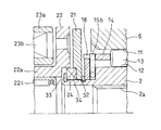
- the electromagnetic clutch 20 is slidably fitted on the small diameter shaft portion 5 of the inner ring 2 and has an armature 21 axially opposed to the end face of the cage 14, and the armature 21 and shaft thereof. It comprises a rotor 22 facing in the direction, an electromagnet 23 facing the rotor 22 in the axial direction, and a separating spring 24 for pressing the armature 21 in a direction away from the rotor 22.
- an engagement hole 25 is formed in the armature 21, and a projection piece 26 provided on the outer edge of the spring retainer 19 is inserted in the engagement hole 25.
- the engagement between the projection 26 and the engagement hole 25 prevents the armature 21 from rotating with respect to the holder 14 via the spring retainer 19 and is axially slidable.
- the rotor 22 has cylindrical portions 22 a and 22 b on the inner and outer peripheries, and a non-magnetic rotor guide 27 in which the cylindrical portion 22 b on the outer periphery is mounted in the open end of the outer ring 6. And is locked to the outer ring 6.
- a bearing 22 c for rotatably supporting an input shaft (not shown) is provided on the inner diameter surface of the inner cylindrical portion 22 a of the rotor 22.
- the electromagnet 23 comprises a field core 23a and an electromagnetic coil 23b supported by the field core 23a.
- the electromagnet 23 is disposed between the inner and outer cylindrical portions 22 a and 22 b of the rotor 22, and the field core 23 a is non-rotatably supported at the closed end of the housing 1.
- a washer 29 is interposed between the field core 23 a and the housing 1.
- an engagement groove 30 and an engagement groove 31 are formed in two rows, and a snap ring 32 and a snap ring 33 are fitted respectively.
- the retaining ring 32 on the side closer to the cam ring 3 abuts when the armature 21 separates from the rotor 22 to limit the amount of separation.
- the retaining ring 33 remote from the cam ring 3 supports the end of the separating spring 24 as described later.
- the separation spring 24 is provided between the armature 21 and the rotor 22.
- One end of the both ends of the separating spring 24 is supported by coming into contact with the attracting surface of the armature 21 to the rotor 22. Further, the other end of the separation spring 24 is supported by coming into contact with a snap ring 33 as a spring receiving convex portion. As illustrated, the separation spring 24 and the rotor 22 are in a non-contact state.
- the configuration of the rotation transmission device of the embodiment is as described above, and in the state where the energization of the electromagnetic coil 23b of the electromagnet 23 is cut off, the roller 13 is held in the neutral state by the spring force of the switch spring 15 as shown in FIG. Therefore, the rotation of the inner ring 2 is not transmitted to the outer ring 6, and the two-way clutch is in a torque cutoff state, causing the inner ring 2 to slip.
- the frictional resistance acting on the attraction surfaces of the rotor 22 and the armature 21 is the rotational resistance of the holder 14, but the frictional resistance is set to a value larger than the spring force of the switch spring 15 in advance. For this reason, the switch spring 15 is elastically deformed and the inner ring 2 and the retainer 14 rotate relative to each other. Due to the relative rotation, the cage 14 is displaced from the neutral position, and the roller 13 is pushed into the narrow portion of the wedge-shaped space and engaged with the cylindrical surface 11 and the cam surface 12. Therefore, the two-way clutch is in a torque transmitting state, and the rotation of the inner ring 2 is transmitted to the outer ring 6 via the roller 13.
- both ends of the separating spring 24 are supported by the armature 21 and the rotor 22, respectively, there is a risk that the separating spring 24 may be worn due to the rotational difference at the both ends, and the spring force may be reduced. Since both ends of the separating spring 24 are respectively supported by the retaining ring 33 provided on the inner ring 2 and the armature 21 rotating integrally with the inner ring 2, no difference in rotation occurs between the ends of the separating spring 24 and wear occurs. Can be suppressed. Therefore, a decrease in the spring force of the separation spring 24 is prevented, and a highly reliable rotation transmission device having high responsiveness of the two-way clutch 10 can be obtained.
- FIG. 5 shows the rotation transmission device of the second embodiment.
- the spring end storage groove 34 is provided on the inner diameter side of the suction surface of the armature 21 to the rotor 22 and the end of the separation spring 24 supported by the armature 21 is the spring end storage groove. It is stored in 34.
- the snap ring is shown as an example of the spring receiving convex portion for supporting the end opposite to the side supported by the armature 21 of the separating spring 24.
- the present invention is not limited to this. It may be a spring receiving convex portion integrally formed on the outer diameter surface of the inner ring 2. Further, the spring receiving convex portion does not have to be provided on the entire circumference of the outer diameter surface of the inner ring, and may be provided intermittently or partially.
- an inner ring and an outer ring separated from an input shaft or an output shaft were shown as an example of an inward member or an outward member, it is not limited to this, an inward member or an outward member is input It may be integrated with the shaft or the output shaft.
- the roller is shown as an example of the engaging element of the two-way clutch, it is not limited to this, and a ball or the like may be used.
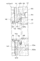
- the rotation transmission device includes a first axis S1, a second axis S2 coaxially disposed with the first axis S1, and transmission of rotation from the first axis S1 to the second axis S2. And an electromagnetic clutch 140 for controlling engagement and disengagement of the two-way clutch 110.
- an electromagnetic clutch 140 for controlling engagement and disengagement of the two-way clutch 110.
- the first axis S1 is on the input side, and the input shaft S1 'is inserted through the hole provided in the axial center of the first axis S1, and the connection shaft 117 such as serration or spline is used to The one axis S1 and the input shaft S1 'are integrally rotatable.
- the second shaft S2 is on the output side, and the output shaft S2 'is inserted through the hole provided at the axial center of the end of the second shaft S2, and the second shaft S2 and the output shaft S2' can be integrally rotated. It has become.
- shaft S2 and output-shaft S2' respectively with the integral member is also considered.
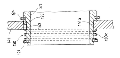
- the electromagnetic clutch 140 is provided on the first shaft S 1 and is juxtaposed to the two-way clutch 110, and the two-way clutch 110 and the electromagnetic clutch 140 are covered by a cylindrical housing 111.
- the shaft end of the input shaft S1 ′ is inserted into the shaft insertion hole 113 formed in the end wall 112 of the housing 111, and the bearing 118 incorporated in the shaft insertion hole 113 and the inner diameter side of the electromagnetic clutch 140 It is rotatably supported with respect to the housing 111 by the incorporated bearing 158 and the like.
- a seal member 159 seals the space between the shaft end of the input shaft S1 'and the inner periphery of the other end of the first shaft S1.
- the output shaft S2 ' is rotatable relative to the housing 111 by a bearing 115 incorporated in the opening at the other end of the housing 111, and is supported in a non-movable state in the axial direction by snap rings 115a, 115b, 150, etc. ing.
- a seal member 116 seals between the output shaft S 2 ′ and the inner periphery of the other end portion of the housing 111.
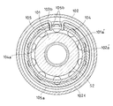
- the two-way clutch 110 includes an annular outer member 102 provided on the second shaft S2, an inner member 101 provided on the first shaft S1 and incorporated inside the outer member 102, and an inner member thereof. It is a two-way roller clutch provided with a roller 104 as an engaging element incorporated between opposing portions of the outer member 102 and the outer member 102, and an annular retainer 103 for holding the roller 104 and the like.
- the inward member 101 and the outward member 102 are each formed of a member integral with the first axis S1 and the second axis S2, respectively, the inward member 101 and the first axis S1 or the outward direction
- the member 102 and the second axis S2 may be configured as separate members, and may be integrated with each other by connection means such as serrations or splines.
- a small diameter cylindrical portion smaller in diameter than the inward member 101 is provided on both ends of the inward member 101 in the axial direction of the first shaft S1, and a small diameter cylindrical portion on the other axial end side facing the second shaft S2 Is rotatably supported by the bearing 119 relative to the second axis S2.
- the members indicated by reference numerals 119a and 119b in the figure are retaining rings for fixing the bearing 119 in the axial direction with respect to the first axis S1 and the second axis S2.
- a plurality of flat cam surfaces 101a forming a wedge space in which both ends in the circumferential direction are narrowed with the cylindrical surface 102a formed on the inner periphery of the outer member 102 It is formed at equal intervals along the direction.
- a cylindrical roller 104 is incorporated between each cam surface 101a and the cylindrical surface 102a.
- pockets 103a are formed at positions radially opposed to the cam surface 101a of the inward member 101, and the rollers 104 are accommodated in the pockets 103a.
- the roller 104 is a cylindrical member having a rolling surface 104 a on the outer periphery.
- the retainer 103 is provided with an inward flange 103 c at an end on the other axial end side facing the first axis S ⁇ b> 1.
- the flange 103 c is rotatably fitted in the small diameter cylindrical portion on the other axial end side of the inward member 1. Further, the flange 103 c is positioned in the axial direction by a snap ring 125 attached to the outer periphery of the small diameter cylindrical portion on the other axial end side of the inward member 1.
- a neutral holding elastic member 105 resiliently holds the cage 103 at a neutral position where the roller 104 disengages from the cylindrical surface 102a and the cam surface 101a on the small diameter cylindrical portion at one axial end side of the inward member 101. It is provided.
- a switch spring hereinafter referred to as a switch spring 105 shown in FIG. 10 is adopted as the neutral holding elastic member 105, but a spring or the like of another type may be used.
- the switch spring 105 has a configuration in which a pair of engagement pieces 105b are provided outward at both ends of a ring portion 105a having a separation end in a part in the circumferential direction.
- the ring portion 105a is fitted on the outer diameter surface of the small diameter cylindrical portion and fitted in a circular recess 101c formed on one end surface of the inner member 101, and the pair of engagement pieces 105b are circular. It inserts in the notch 103b formed in the end part of the holder
- the switch spring 105 By the incorporation of the switch spring 105, the pair of engagement pieces 105b press opposite ends in the circumferential direction of the notch 101b and the notch 103b in opposite directions. As a result of the pressure, the holder 103 is elastically held at the neutral position where the roller 104 is disengaged from the cylindrical surface 102a and the cam surface 101a. That is, when the switch spring 105 is elastically deformed by relative rotation of the holder 103 with respect to the inward member 101, the switch spring 105 biases the holder 103 in the circumferential direction so that the roller 104 is maintained at the neutral position by its elastic force. .
- a protruding piece portion 103 d is provided at an end of the holder 103 at one axial end side.
- the projecting portion 103 d is slidably fitted in a hole 143 provided in the armature 141. As a result, the armature 141 is locked against the holder 103.
- the electromagnetic clutch 140 is rotationally supported with respect to the first shaft S1 and an armature 141 supported in a rotatable manner in the axial direction with respect to the first shaft S1 while being prevented from rotating with respect to the retainer 103.
- An electromagnet 144 axially opposed to the armature 141 and a separating spring (hereinafter referred to as a separating spring 120) as an elastic member 120 biasing the armature 141 in a direction away from the electromagnet 144 are provided.
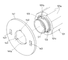
- the electromagnet 144 includes a rotor 145 made of a magnetic material, and an electromagnetic coil 146 held by the rotor 145.
- the rotor 145 is formed of a tubular member having a U-shaped cross section in which the inner cylinder portion and the outer cylinder portion are connected by an end wall on the other end side in the axial direction. An end wall of the other end side in the axial direction of the rotor 145 is opposed to the armature 141, and supported rotatably relative to the first axis S1 by a bearing 158 incorporated between the inner cylindrical portion and the first axis S1. ing.
- the rotor 145 is connected to the outward member 102 of the two-way clutch 110 via a nonmagnetic body cylinder 147 and rotates integrally with the outward member 102.
- a projection is provided on the outer diameter surface of the end of the outer member 102 in the axial direction one end side, and the projection is used as the other axial end of the cylinder 147 It is fitted in the notch which opens in the inside diameter side of the end of the side, and further, it is considered as the retention prevention of the projection by the snap ring 150 attached to the outside diameter side of the cylindrical body 147.
- the projection 151 is provided on the outer diameter surface of the one end of the outer cylinder fitted to the end of the cylinder 147 at one end in the axial direction.
- the protrusion 151 is engaged with a notch 152 which is open in the inner diameter surface on one end side in the axial direction of the cylindrical body 147, and is further prevented by the retaining ring 153 attached to the inner diameter surface of the cylindrical body 147.
- One axial end of the electromagnetic coil 146 is held in contact with a plate 154 fixed to the housing 111.
- the plate 154 is fixed in a state in which the axial movement is restricted with respect to the housing 111 via the retaining ring 155 and the shim 156.
- the armature 141 prevents relative rotation with the first axis S1 when the electromagnet 144 is deenergized by meshing between the protrusion 123 provided on the first axis S1 and the notch 142 provided on the armature 141. It is done. When the electromagnet 144 is energized, this meshing is released, and the first shaft S1 and the armature 141 are in a relatively rotatable state.
- the projection 123 is provided such that a portion thereof protrudes to the outer diameter side along the circumferential direction of the outer periphery of the cylindrical portion for supporting the armature 141 in the first axis S1, and the notch 142 is The part is provided so as to be recessed along the circumferential direction of the inner circumference 141a of the hole of the axial center of the armature 141.
- the protrusion 123 is provided on the outer circumference of the first axis S1.
- a portion of the flange portion is provided so as to protrude in the axial direction from the side surface (surface facing in the axial direction), and the notch 142 is partially recessed in the side surface (surface facing in the axial direction) of the armature 141 Aspects provided as such are also conceivable.
- the protrusions 123 and the corresponding notches 142 can be provided at a plurality of locations (three locations in the embodiment) along the circumferential direction, as shown in FIGS. 9 and 12, but can exhibit the function of preventing relative rotation. In this case, at least one protrusion 123 and the corresponding notch 142 may be provided at any one of the circumferential positions.
- the projection 123 is provided on the first axis S1, and the notch 141 corresponding to this is provided on the armature 141 to exhibit the relative rotation preventing function, so that the projection 123 can be used during forging of the first axis S1.
- the projection 123 can be molded at the same time.
- the projection 123 can be formed of a member integral with the first axis S1, there is no particular limitation in setting of the thickness, and securing of the strength is easy.
- the protrusion 123 and the notch 142 may be interchanged, and the notch 142 may be provided on the first axis S1 and the protrusion 123 may be provided on the armature 41.
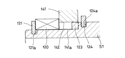
- the separating spring 120 is supported between the armature 141 and the locking portions 121 and 122 provided on the first axis S1.
- One end of the separating spring 120 is supported by the locking portions 121 and 122, and the other end of the separating spring 120 is supported by the armature 141, and is elastically tensioned in the direction of separating the locking portions 121 and 122 from the armature 141. It is a structure.
- the locking portion 121 is a locking ring fitted to the first shaft S1.
- the retaining ring 121 is a locking ring fitted to the first shaft S1.
- the cylindrical portion for supporting the armature 141 in the first axis S1 has a snap ring groove 121a at an end on one end side in the axial direction, and the snap ring 121 is inserted into the snap ring groove 121a.
- a C-shaped member in which one portion of the annular member is divided is adopted as the retaining ring 121.
- the separating spring 120 Since the separating spring 120 is disposed between the side surface of the retaining ring 121 and the side surface of the armature 141, the separating spring 120 bears the reaction force on the retaining ring 121, and the armature 141 is held by its elastic force. It always presses in the direction away from the rotor 145 (the other end side in the axial direction).
- the separating spring 120 separates the armature 141 and the rotor 145, when the armature 141 and the rotor 145 rotate relative to each other, the first shaft S1 and the separating spring 120, the separating spring 120, and the armature 141 Since there is no sliding part between them, it is possible to prevent the occurrence of wear of the members.
- the roller 104 of the two-way clutch 110 is against the cylindrical surface 102 a of the outer member 102 and the cam surface 101 a of the inner member 101 as shown in FIG. Is held in the neutral position for disengaging. That is, the roller 104 is located near the center of the cam surface 101a (near the center with respect to the circumferential direction), and the two-way clutch 110 is in the disengaged state.
- the rotation transmission device may use either the first axis S1 or the second axis S2 as the input side.
- the rotation in the case where the first shaft S1 is connected to the input shaft S1 ′ and used, when the first shaft S1 rotates in a state where the two-way clutch 110 is disengaged, the rotation is The first axis S1 and the inward member 1 are free rotated without being transmitted to the two axes S2 (see FIG. 10).
- the rotation of the inner member 101 is transmitted to the holder 103 via the switch spring 105, and the holder 103 and the roller 104 rotate together. Further, since the armature 141 is detentated by the holder 103, the armature 141 also rotates.
- the armature 141 moves in the axial direction toward the rotor 145, the meshing between the projection 123 and the notch 142 is released, and the armature 141 is in a state of being able to rotate relative to the first axis S1.
- the rotor 145 is connected to the outer member 102 through the cylindrical body 147, so the holder 103 is connected to the outer member 102 by adsorption of the armature 141, and the holder 103 and the inner member 101 rotate relative to each other.
- the holder 103 rotates relative to the first axis S1 (inner member 101) together with the armature 141.
- the movement of the armature 141 in the axial direction is guided by the projecting portion 103 d provided on the holder 103.
- the projecting piece portion 103 d is axially slidably inserted in the detent hole 143 provided in the armature 141, so that the projecting piece portion 103 d advances and retracts in the detent hole 143 as the armature 141 moves in the axial direction. By doing this, the axial movement of the armature 141 is guided.
- a connector (not shown) to which a wire for supplying electricity is connected is attached to the end wall 112 of the housing 111, and a brush provided on the connector and an annular contact provided on the rotor 145 The electric coil 146 is supplied with electricity by the contact of
- the relative rotation between the holder 103 and the inward member 101 causes the roller 104 to engage with the cylindrical surface 102a of the outward member 102 and the cam surface 101a of the inward member 101, and the two-way clutch 110 is engaged.
- the rotation of the inward member 101 is transmitted to the outward member 102, and the second shaft S2 is rotated.
- FIG. 13A to 13C show a specific configuration of the separation spring 120 used in each of the above embodiments.
- a disc spring 120 a is employed as the separation spring 120.
- a plurality of disc springs 120a may be arranged along the axial direction.
- the wave spring 120 b is adopted as the separation spring 120.
- a coil spring 120c is adopted as the separation spring 120.
- the separating spring 120 one having various configurations can be adopted.
- a fourth embodiment is shown in FIG.
- a recess provided in the first shaft S1 is employed as the locking portion 122 for supporting the separation spring 120 on the first shaft S1.
- a concave portion 122 it is referred to as a concave portion 122.
- the separating spring 120 Since the separating spring 120 is disposed between the side surface at one end in the axial direction in the recess 122 and the side surface of the armature 141, the separating spring 120 bears a reaction force on the side surface in the recess 122, The elastic force can always press the armature 141 in the direction (the other axial end side) away from the rotor 145.
- the recess 122 can be formed on the outer periphery of the first axis S1, there is an advantage that it is not necessary to attach a separate member as in the case where the snap ring 121 is adopted.
- the recess 122 also has an advantage that it can be formed simultaneously with the forging of the first axis S1.
- shaft S1 is employable as the latching
- the convex portion is formed of a member integral with the member constituting the first axis S1, there is also an advantage that it is not necessary to attach another member to the first axis S1.
- the convex portion has an advantage that it can be simultaneously formed at the time of forging of the first axis S1.
- the convex portion may be intermittent along the circumferential direction of the outer periphery of the first axis S1 as long as the separation spring 120 is locked, or may be continuous along the circumferential direction of the outer periphery It may be one.
- the convex portion may be a ridge extending over the entire outer periphery of the first axis S1.
- the separating spring 120 is expanded in diameter by the centrifugal force accompanying the high speed rotation depending on its structure, and predetermined performance is obtained. In some cases it can not be demonstrated. For this reason, it is desirable to properly select one of the plurality of types of disjunction springs 120 according to the range of rotation speed (centrifugal force) in which the rotation transmission device is used.
- a coil spring can be adopted as the separation spring 120 in a rotation transmission device used in a low rotation range where the centrifugal force is relatively small.
- Coil springs have the advantage of low cost.
- a disc spring can be adopted as the separation spring 120 in the rotation transmission device used in the high rotation range where the centrifugal force is relatively large.
- the disc spring may have a relatively high cost, but can exert predetermined performance even under a large centrifugal force.
- a wave spring can be employed as the separation spring 120 in an intermediate region between the high rotation region and the low rotation region. The wave spring can exert an intermediate performance between the coil spring and the disc spring in the resistance to centrifugal force, and is similar in cost.
- the separation spring 120 can be easily locked in the recess 122.
- a wave spring or a disc spring a notch is provided in a part of the annular member in the circumferential direction, and the outer diameter of the annular member changes with expansion and contraction of the width of the notch. .
- the wave spring or disc spring changes its outer diameter with respect to the shaft to which it is attached (expansion), and is fitted into the recess 122, and after being fitted, is returned to the original outer diameter and fixed .
- the two-way clutch 110 is configured between the inward member 101 provided on the first shaft S1 and the outward member 102 provided on the second shaft S2, and the outward member 102 is configured.
- a cylindrical surface 102a is provided on the inner periphery of the cam and a cam surface 101a is provided on the outer periphery of the inward member 101.
- a configuration in which the cam surface 101a is reversed inside and outside can be adopted.
- the two-way clutch 110 has a cylindrical surface 101 a ′ on the outer periphery of the member 101 and a cam surface 102 a ′ on the inner periphery of the outer member 102.
- the elastic member 120 is disposed on the inner periphery of the second axis S2, there is an advantage that it is not necessary to consider the deformation of the elastic member 120 due to the centrifugal force.
- the second shaft S2 is fixed to the electromagnet 144, the armature 141 is supported movably in the axial direction with respect to the first shaft S1, and the locking portions 121 and 122 for locking the separating spring 120 are the first shaft S1.
- the same points are provided to the
- the first shaft S1 is fixed to the electromagnet 144, the armature 141 is supported movably in the axial direction with respect to the second shaft S2, and the locking portions 121 and 122 for locking the separating spring 120 are the second
- shaft S2 is also considered.
- the locking portions 121 and 122 are provided on the second axis S2, the locking portions 121 and 122 can be provided on the outer periphery of the second axis S2.
- the locking portions 121 and 122 may be configured to be provided on the inner periphery of the second shaft S2.
- the locking portions 121 and 122 provided on the inner periphery of the second shaft S2 include, for example, a retaining ring 121 fitted on the inner periphery of the second shaft S2 and a convex integrally provided on the inner periphery of the second shaft S2.
- a concave portion 122 or the like provided on the inner circumference of the second shaft S2 can be employed.
- FIG. 16 a sixth embodiment is shown in FIG. In the embodiment of FIG. 16, the first shaft S1 and the second shaft S2 are engaged and released only by the electromagnetic clutch 140 without using the two-way clutch 110.
- the electromagnetic clutch 140 includes an armature 141 axially movable with respect to the first axis S1 or the second axis S2, an electromagnet 144 rotatable about the axis with respect to the armature 141 and axially facing the armature 141, and an armature And a separating spring 120 for urging the 141 in a direction away from the electromagnet 144.
- the armature 141 is axially movable with respect to the first axis S1, and the electromagnet 144 is supported so as to be rotatable around the first axis S1.
- the armature 141 and the first axis S1 are supported movably in the axial direction by engagement by splines indicated by reference numerals 148 and 126 in the figure, or by engagement of a convex portion and a concave portion provided along the circumferential direction, etc. Further, the armature 141 and the first axis S1 are integrally rotatable around the axis.
- the separation spring 120 is supported by locking portions 121 and 122 provided on a first axis S ⁇ b> 1 that supports the armature 141 so as to be movable in the axial direction. Therefore, the separation spring 120 is rotatable with respect to the electromagnet 144.
- the concave portion 122 is adopted as the locking portion 121, 122, but it is fixed to the convex portion integrally formed with the shaft as the locking portion 121, 122 or to the shaft as in the above embodiment. Retaining ring 121 grade
- the armature 141 is axially movable with respect to the second axis S2, and the electromagnet 144 is supported so as to be rotatable about the second axis S2.
- the locking portions 121 and 122 for supporting the separating spring 120 are provided on the second axis S2.
- the first axis S1 is the input side and the second axis S2 is the output side
- the first axis S1 is the output side
- the second axis S2 is the input side by reversing this. It is also good.
- the specification of the two-way clutch 110 is not limited to the above-described embodiment, and various clutches that can control engagement and release by the electromagnetic clutch 140 are adopted. be able to.
- the configuration of the spring end storage groove 34 used in the second embodiment can be adopted.
- the spring end storage groove 34 is provided on the inner diameter side of the suction surface of the armature 21 to the rotor 22, and the end of the separation spring 120 supported by the armature 141 is stored in the spring end storage groove 34.
Landscapes
- Engineering & Computer Science (AREA)
- General Engineering & Computer Science (AREA)
- Mechanical Engineering (AREA)
- Physics & Mathematics (AREA)
- Electromagnetism (AREA)
- Arrangement And Mounting Of Devices That Control Transmission Of Motive Force (AREA)
Abstract
La présente invention adopte un dispositif de transmission de rotation dans lequel une partie d'extrémité d'un ressort de séparation (24) est supportée en étant mise en contact avec une surface d'aspiration d'un induit (21) avec un rotor (22), et l'autre partie d'extrémité proche du rotor (22) est supportée par une bague de fixation (33) insérée dans une rainure de mise en prise (31) d'une partie d'arbre de petit diamètre d'une bague intérieure (2). Comme la bague intérieure (2) et l'induit (21) tournent d'un seul tenant lors de la coupure de l'alimentation électrique vers un embrayage électromagnétique, il n'y a pas de différence de rotation entre les éléments supportant les deux extrémités du ressort de séparation (24). Par conséquent, l'usure due à la différence de rotation ne se produit pas dans le ressort de séparation (24), contrairement au cas où la partie d'extrémité sur un côté du ressort de séparation (24) est supportée en étant mise en contact avec le rotor (22).
Applications Claiming Priority (4)
| Application Number | Priority Date | Filing Date | Title |
|---|---|---|---|
| JP2017-182299 | 2017-09-22 | ||
| JP2017182299A JP2019056453A (ja) | 2017-09-22 | 2017-09-22 | 回転伝達装置 |
| JP2018-001275 | 2018-01-09 | ||
| JP2018001275A JP2019120340A (ja) | 2018-01-09 | 2018-01-09 | 回転伝達装置 |
Publications (1)
| Publication Number | Publication Date |
|---|---|
| WO2019059358A1 true WO2019059358A1 (fr) | 2019-03-28 |
Family
ID=65811284
Family Applications (1)
| Application Number | Title | Priority Date | Filing Date |
|---|---|---|---|
| PCT/JP2018/035101 Ceased WO2019059358A1 (fr) | 2017-09-22 | 2018-09-21 | Dispositif de transmission de rotation |
Country Status (1)
| Country | Link |
|---|---|
| WO (1) | WO2019059358A1 (fr) |
Citations (6)
| Publication number | Priority date | Publication date | Assignee | Title |
|---|---|---|---|---|
| JPS5245725Y2 (fr) * | 1971-06-08 | 1977-10-18 | ||
| JPS5329868Y2 (fr) * | 1972-05-23 | 1978-07-26 | ||
| JPH0496626U (fr) * | 1991-01-30 | 1992-08-21 | ||
| JP2001050302A (ja) * | 1999-08-10 | 2001-02-23 | Ntn Corp | 回転伝達装置 |
| JP2004308784A (ja) * | 2003-04-07 | 2004-11-04 | Ntn Corp | 逆回転防止用クラッチユニットおよび坂道逆走行防止システム |
| JP2005307604A (ja) * | 2004-04-22 | 2005-11-04 | Ntn Corp | 自動車用電動ドア開閉装置 |
-
2018
- 2018-09-21 WO PCT/JP2018/035101 patent/WO2019059358A1/fr not_active Ceased
Patent Citations (6)
| Publication number | Priority date | Publication date | Assignee | Title |
|---|---|---|---|---|
| JPS5245725Y2 (fr) * | 1971-06-08 | 1977-10-18 | ||
| JPS5329868Y2 (fr) * | 1972-05-23 | 1978-07-26 | ||
| JPH0496626U (fr) * | 1991-01-30 | 1992-08-21 | ||
| JP2001050302A (ja) * | 1999-08-10 | 2001-02-23 | Ntn Corp | 回転伝達装置 |
| JP2004308784A (ja) * | 2003-04-07 | 2004-11-04 | Ntn Corp | 逆回転防止用クラッチユニットおよび坂道逆走行防止システム |
| JP2005307604A (ja) * | 2004-04-22 | 2005-11-04 | Ntn Corp | 自動車用電動ドア開閉装置 |
Similar Documents
| Publication | Publication Date | Title |
|---|---|---|
| US8448764B2 (en) | Rotation transmission device | |
| US8272487B2 (en) | Rotation transmission device | |
| US6257386B1 (en) | Power cut/connect device | |
| CN105934601B (zh) | 旋转传递装置 | |
| CN110945260A (zh) | 离合器以及车辆的动力传递结构 | |
| US9109642B2 (en) | Rotation transmission device | |
| EP3369958B1 (fr) | Agencement d'attraction pour und dispositif de transmission de rotation | |
| US11346403B2 (en) | Rotation braking device | |
| WO2019059358A1 (fr) | Dispositif de transmission de rotation | |
| JP7108506B2 (ja) | 回転伝達装置 | |
| JP4732200B2 (ja) | 回転伝達装置 | |
| US7086513B2 (en) | Rotation transmission device | |
| JP7262267B2 (ja) | 回転伝達装置 | |
| WO2019138933A1 (fr) | Dispositif de transmission de rotation | |
| JP2019120340A (ja) | 回転伝達装置 | |
| JP4907301B2 (ja) | 回転伝達装置 | |
| JP2019056453A (ja) | 回転伝達装置 | |
| JP2007187249A (ja) | 回転伝達装置 | |
| JP2020051530A (ja) | 回転伝達装置 | |
| WO2024043172A1 (fr) | Dispositif de transmission de rotation | |
| JP2012122563A (ja) | 係合装置 | |
| JP2020125811A (ja) | 回転伝達装置 | |
| JP2005308052A (ja) | 回転伝達装置 | |
| JP2005155659A (ja) | 回転伝達装置 | |
| JP2020003032A (ja) | 回転伝達装置 |
Legal Events
| Date | Code | Title | Description |
|---|---|---|---|
| 121 | Ep: the epo has been informed by wipo that ep was designated in this application |
Ref document number: 18859592 Country of ref document: EP Kind code of ref document: A1 |
|
| NENP | Non-entry into the national phase |
Ref country code: DE |
|
| 122 | Ep: pct application non-entry in european phase |
Ref document number: 18859592 Country of ref document: EP Kind code of ref document: A1 |