WO2019059383A1 - 油圧ショベル - Google Patents
油圧ショベル Download PDFInfo
- Publication number
- WO2019059383A1 WO2019059383A1 PCT/JP2018/035212 JP2018035212W WO2019059383A1 WO 2019059383 A1 WO2019059383 A1 WO 2019059383A1 JP 2018035212 W JP2018035212 W JP 2018035212W WO 2019059383 A1 WO2019059383 A1 WO 2019059383A1
- Authority
- WO
- WIPO (PCT)
- Prior art keywords
- load
- determination
- loading
- hydraulic shovel
- controller
- Prior art date
- Legal status (The legal status is an assumption and is not a legal conclusion. Google has not performed a legal analysis and makes no representation as to the accuracy of the status listed.)
- Ceased
Links
Images








Classifications
-
- E—FIXED CONSTRUCTIONS
- E02—HYDRAULIC ENGINEERING; FOUNDATIONS; SOIL SHIFTING
- E02F—DREDGING; SOIL-SHIFTING
- E02F3/00—Dredgers; Soil-shifting machines
- E02F3/04—Dredgers; Soil-shifting machines mechanically-driven
- E02F3/28—Dredgers; Soil-shifting machines mechanically-driven with digging tools mounted on a dipper- or bucket-arm, i.e. there is either one arm or a pair of arms, e.g. dippers, buckets
- E02F3/36—Component parts
- E02F3/42—Drives for dippers, buckets, dipper-arms or bucket-arms
- E02F3/43—Control of dipper or bucket position; Control of sequence of drive operations
- E02F3/431—Control of dipper or bucket position; Control of sequence of drive operations for bucket-arms, front-end loaders, dumpers or the like
- E02F3/434—Control of dipper or bucket position; Control of sequence of drive operations for bucket-arms, front-end loaders, dumpers or the like providing automatic sequences of movements, e.g. automatic dumping or loading, automatic return-to-dig
-
- E—FIXED CONSTRUCTIONS
- E02—HYDRAULIC ENGINEERING; FOUNDATIONS; SOIL SHIFTING
- E02F—DREDGING; SOIL-SHIFTING
- E02F9/00—Component parts of dredgers or soil-shifting machines, not restricted to one of the kinds covered by groups E02F3/00 - E02F7/00
- E02F9/26—Indicating devices
-
- E—FIXED CONSTRUCTIONS
- E02—HYDRAULIC ENGINEERING; FOUNDATIONS; SOIL SHIFTING
- E02F—DREDGING; SOIL-SHIFTING
- E02F3/00—Dredgers; Soil-shifting machines
- E02F3/04—Dredgers; Soil-shifting machines mechanically-driven
- E02F3/28—Dredgers; Soil-shifting machines mechanically-driven with digging tools mounted on a dipper- or bucket-arm, i.e. there is either one arm or a pair of arms, e.g. dippers, buckets
- E02F3/30—Dredgers; Soil-shifting machines mechanically-driven with digging tools mounted on a dipper- or bucket-arm, i.e. there is either one arm or a pair of arms, e.g. dippers, buckets with a dipper-arm pivoted on a cantilever beam, i.e. boom
- E02F3/32—Dredgers; Soil-shifting machines mechanically-driven with digging tools mounted on a dipper- or bucket-arm, i.e. there is either one arm or a pair of arms, e.g. dippers, buckets with a dipper-arm pivoted on a cantilever beam, i.e. boom working downwardly and towards the machine, e.g. with backhoes
-
- E—FIXED CONSTRUCTIONS
- E02—HYDRAULIC ENGINEERING; FOUNDATIONS; SOIL SHIFTING
- E02F—DREDGING; SOIL-SHIFTING
- E02F9/00—Component parts of dredgers or soil-shifting machines, not restricted to one of the kinds covered by groups E02F3/00 - E02F7/00
- E02F9/20—Drives; Control devices
- E02F9/2004—Control mechanisms, e.g. control levers
-
- E—FIXED CONSTRUCTIONS
- E02—HYDRAULIC ENGINEERING; FOUNDATIONS; SOIL SHIFTING
- E02F—DREDGING; SOIL-SHIFTING
- E02F9/00—Component parts of dredgers or soil-shifting machines, not restricted to one of the kinds covered by groups E02F3/00 - E02F7/00
- E02F9/20—Drives; Control devices
- E02F9/2025—Particular purposes of control systems not otherwise provided for
-
- E—FIXED CONSTRUCTIONS
- E02—HYDRAULIC ENGINEERING; FOUNDATIONS; SOIL SHIFTING
- E02F—DREDGING; SOIL-SHIFTING
- E02F9/00—Component parts of dredgers or soil-shifting machines, not restricted to one of the kinds covered by groups E02F3/00 - E02F7/00
- E02F9/20—Drives; Control devices
- E02F9/22—Hydraulic or pneumatic drives
- E02F9/2264—Arrangements or adaptations of elements for hydraulic drives
- E02F9/2271—Actuators and supports therefor and protection therefor
-
- G—PHYSICS
- G01—MEASURING; TESTING
- G01G—WEIGHING
- G01G19/00—Weighing apparatus or methods adapted for special purposes not provided for in the preceding groups
- G01G19/08—Weighing apparatus or methods adapted for special purposes not provided for in the preceding groups for incorporation in vehicles
- G01G19/10—Weighing apparatus or methods adapted for special purposes not provided for in the preceding groups for incorporation in vehicles having fluid weight-sensitive devices
-
- G—PHYSICS
- G01—MEASURING; TESTING
- G01G—WEIGHING
- G01G19/00—Weighing apparatus or methods adapted for special purposes not provided for in the preceding groups
- G01G19/14—Weighing apparatus or methods adapted for special purposes not provided for in the preceding groups for weighing suspended loads
- G01G19/16—Weighing apparatus or methods adapted for special purposes not provided for in the preceding groups for weighing suspended loads having fluid weight-sensitive devices
Definitions
- the present invention relates to a hydraulic shovel that calculates the loading weight of a work object loaded in a transport machine.
- a working machine represented by a hydraulic shovel, such as dumping of minerals in a mine and loading on a dump truck, dumps (sometimes referred to as "work objects” in this paper) such as dump trucks, etc.
- dumps sometimes referred to as "work objects” in this paper
- work trucks etc.
- the loading amount to the transport machine (total weight of the work objects on the transport machine) can be made appropriate during this kind of work, the drop in production due to lack of loading and the waste of reloading due to overloading To improve on-site production efficiency.
- the general method of adjusting the loading amount to the transport machine is to measure the load of the excavated object while transporting the excavated object while the hydraulic shovel (loading machine) transports the excavated object, and to measure it during the loading operation to the transport machine
- the loading amount to the transport machine is calculated by integrating the calculated load, and the calculated amount is presented to the operator of the hydraulic shovel. Since the loading amount to the transporting machine can be presented, the operator of the hydraulic shovel can adjust the digging amount after the next time, so that the loading amount to the transporting machine can be made appropriate. In addition, the operator of the hydraulic shovel can judge whether or not to be overloaded by loading the excavated material being transported by presenting the loading amount to the transport machine and the load of the excavated material being transported, It becomes possible to prevent overloading in advance.
- Japanese Patent No. 3787046 discloses a load in a bucket during a turning operation for transporting a transported object (object to be worked) to the transporting machine, and releasing the transported object as a transporting machine
- the load difference of the load in the bucket during the turning operation is greater than or equal to a predetermined value and the bucket dump operation is performed in a predetermined angular range in the turning direction, the load in the bucket immediately before the bucket dump operation
- a work load monitoring device for a hydraulic shovel is disclosed which measures and integrates as the weight of the transported object.
- An object of the present invention is to provide a hydraulic shovel capable of detecting the input of a work object to a transport machine without error and accurately outputting the loading amount of the transport machine.
- the present application includes a plurality of means for solving the above problems, and an example thereof is a hydraulic cylinder driven by pressure oil discharged from a hydraulic pump, a work machine driven by the hydraulic cylinder, and
- a hydraulic shovel provided with a controller for calculating the loading weight of a work object loaded in a transport machine by a work machine
- the controller is a work target for the transport machine by the hydraulic shovel based on the posture of the work machine
- a first determination is made to determine whether loading of an object has been performed, and the hydraulic shovel is loaded into the transport machine by the hydraulic shovel based on the thrust of the hydraulic cylinder and the determination result of the first determination.
- the first load which is the load of the work object, is calculated, and the determination result of the first determination and the transport machine side controller provided in the transport machine are transmitted. It is determined whether or not the first load is integrated based on the determination result of the second determination that determines whether loading of the work object onto the transport machine has been performed by the hydraulic shovel A third determination is performed, and when it is determined that the first load is integrated by the third determination, the loading weight of the transport machine is calculated by integrating the first load.
- the present invention it is determined based on the information of both the hydraulic shovel and the transport machine that the loading of the work target has been completed, so that there is no mistake that the hydraulic shovel has input the work target to the transport machine It can be detected and the loading amount to the transport machine can be calculated accurately.
- the side view of the hydraulic shovel concerning the embodiment of the present invention The side view of the dump truck concerning the embodiment of the present invention.
- the flowchart by which the controller 40 by the side of dump truck 2 determines the method of determining whether dump truck 2 is engaged in loading operation. 5 is an example of a graph showing the relationship between the detection value of the vehicle speed sensor 43 and the determination result by the loading operation determination unit 57.
- FIG. 9 is a flowchart showing a method of determining whether or not loading of a work target onto the dump truck 2 by the hydraulic excavator 1 has been performed by the controller 40 on the dump truck 2 side.
- the graph which shows an example of the time change of the detection value of suspension pressure sensor 39a of dump truck 2 engaged in loading work.
- the flowchart which shows the method the controller 21 side of the hydraulic shovel 1 determines whether loading of the operation
- 6 is an example of a graph showing the relationship between the detection value of the arm bottom pressure sensor 31 and the detection value of the bucket angle sensor 26 and the determination result by the conveyance determination unit 51.
- FIG. 6 is a flowchart showing a method of determining whether the load measurement system of the present embodiment is abnormal or not, by the controller 21 on the hydraulic shovel 1 side.
- FIG. 10 is a flowchart of processing executed by the load calculation unit 50, the load integration determination unit 55, and the load integration unit 56 in the controller 21 of the hydraulic shovel 1 side.
- the system configuration figure of the load measuring system concerning other embodiments of the present invention.
- the loading machine to which the present invention is applied is not limited to a hydraulic shovel having a bucket as an attachment, but also includes a hydraulic shovel having grapples, lifting magnets, and the like capable of holding and releasing cargo.
- the present invention is also applicable to a wheel loader or the like provided with a working arm without a turning function such as a hydraulic shovel.
- FIG. 1 is a side view of a hydraulic shovel according to the present embodiment
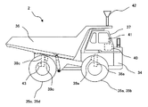
- FIG. 2 is a side view of a dump truck according to the present embodiment.
- the hydraulic shovel 1 shown in FIG. 1 includes a lower traveling body 10, an upper revolving body 11 rotatably provided at an upper portion of the lower traveling body 10, and an articulated work arm mounted in front of the upper revolving body 11.
- a front work machine 12 a swing motor 19 which is a hydraulic motor for rotating the upper swing body 11, an operation room 20 provided on the upper swing body 11 for the operator to get in and operating the shovel 1, and the inside of the operation room 20
- Control lever 22 provided in the control unit 22 for controlling the operation of an actuator mounted on the hydraulic shovel 1, a storage unit (eg, ROM, RAM), an arithmetic processing unit (eg, CPU), and an input / output unit
- a controller 21 that controls the operation of the hydraulic shovel 1.
- the front work machine 12 is provided with a boom 13 rotatably provided on the upper swing body 11, an arm 14 rotatably provided at the tip of the boom 13, and a tip of the arm 14.
- a bucket (attachment) 15 a boom cylinder 16 which is a hydraulic cylinder for driving the boom 13, an arm cylinder 17 which is a hydraulic cylinder for driving the arm 14, and a bucket cylinder 18 which is a hydraulic cylinder for driving the bucket 15 There is.
- the boom cylinder 16, the arm cylinder 17, and the bucket cylinder 18 are driven by pressure oil discharged from a hydraulic pump (not shown) mounted on the upper swing body 11, respectively.
- a boom angle sensor 24, an arm angle sensor 25, and a bucket angle sensor 26 are attached to the pivots of the boom 13, the arm 14 and the bucket 15, respectively.
- the rotation angles of the boom 13, the arm 14 and the bucket 15 can be obtained from the angle sensors 24, 25 and 26, respectively.
- a turning angular velocity sensor 27 and an inclination angle sensor 28 are attached to the upper turning body 11 so that the turning angular velocity of the top turning body 11 and the inclination angle in the front-rear direction of the top turning body 11 can be obtained. There is. From the detection values of the angle sensors 24, 25, 26, 27, 28, the attitude of the front working machine 12 can be specified.
- a boom bottom pressure sensor 29, a boom rod pressure sensor 30, an arm bottom pressure sensor 31, and an arm rod pressure sensor 32 are attached to the boom cylinder 16 and the arm cylinder 17, respectively, so that the pressure inside each hydraulic cylinder can be acquired. It is configured. From the detection values of the pressure sensors 29, 30, 31, 32, it is possible to specify the thrust of each of the cylinders 16, 18, that is, the driving force to be applied to the front working machine 12.
- the boom angle sensor 24, the arm angle sensor 25, the bucket angle sensor 26, the inclination angle sensor 28, and the turning angular velocity sensor 27 can be replaced with other sensors as long as they can detect physical quantities related to the posture of the front work machine 12 is there.
- the boom angle sensor 24, the arm angle sensor 25 and the bucket angle sensor 26 can be replaced by an inclination angle sensor or an inertial measurement unit (IMU), respectively.
- the boom bottom pressure sensor 29, the boom rod pressure sensor 30, the arm bottom pressure sensor 31, and the arm rod pressure sensor 32 relate to the thrust generated by the boom cylinder 16 and the arm cylinder 17, that is, the driving force applied to the front work machine 12.
- Other sensors can be substituted as long as physical quantities can be detected.
- the front work machine 12 can detect the operating speeds of the boom cylinder 16 and the arm cylinder 17 with a stroke sensor, or detect the operating speeds of the boom 13 and the arm 14 with an IMU. The operation of may be detected.
- An external input / output unit 23 for displaying the measurement results of the load measurement system is provided inside the operation room 20, and a wireless communication for the controller 21 to communicate with an external controller (for example, the controller 40) on the upper surface of the upper swing body 11 A transceiver 33 is attached.
- the external input / output unit 23 includes a display unit 23A (see FIG. 3) for displaying the calculation result of the controller 21 and the like, and an input unit 23B (see FIG. 3) for the operator to input information to the controller 21. Is equipped.
- a liquid crystal display can be used as the display device 23A, and a numeric keypad, a touch panel, a keyboard, or the like can be used as the input device 23B.
- the dump truck 2 shown in FIG. 2 includes a vehicle body 34, four tires 35a, 35b, 35c and 35d attached respectively to front and rear axles (not shown) provided on the vehicle body 34, and a load And the operation chamber 37 for the operator to operate the dump truck 2.
- suspensions 38a, 38b, 38c and 38d for supporting the vehicle body 34 are attached to the axle.
- Suspension pressure sensors 39a, 39b, 39c, 39d first vehicle state detectors
- the suspension pressure sensors 39a, 39b, 39c, 39d detect the suspension pressure as a physical quantity related to the weight of the work object loaded on the dump truck 2.
- the vehicle body 34 has a storage device (for example, ROM, RAM), an arithmetic processing unit (for example, CPU) and an input / output device, a controller 40 for controlling the dump truck 2, and an external controller (for example, controller 21). And a display device 41 for displaying the vehicle body information of the dump truck 2 is provided inside the operation room 37. As shown in FIG. As the display device 41, for example, a liquid crystal display can be used. Further, a vehicle speed sensor (third vehicle body state detector) 43 for measuring the traveling speed of the dump truck 2 is provided on the vehicle body 34.
- the suspension pressure sensors 39a, 39b, 39c and 39d can be replaced by other sensors as long as they can detect the physical quantity related to the weight of the work object loaded on the dump truck 2 by the hydraulic shovel 1.
- the vehicle speed sensor 43 may be replaced by another sensor as long as it can detect a physical quantity related to the traveling state of the dump truck 2.
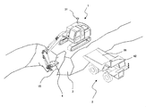
- FIG. 3 and 4 are schematic views showing an example of the operation of the hydraulic shovel 1 during the loading operation.
- the hydraulic shovel 1 of FIG. 3 excavates the work target (excitation target) 3 and loads the work target 4 in the bucket 15 and performs the “digging operation”, and the hydraulic shovel 1 of FIG.
- the “loading operation” is performed to release (release) the work object 4 to the loading platform 36 of the dump truck 2.
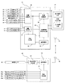
- FIG. 5 is a system configuration diagram of the load measuring system according to the present embodiment, and the functions of the controller 40 and the controller 21 are shown by block diagrams.
- the controller 40 on the dump truck 2 side receives the signals of the suspension pressure sensors 39a, 39b, 39c, 39d and the vehicle speed sensor 43, and calculates information (for example, loading determination and loading operation determination described later) based on these signals. It is comprised so that it can transmit to the controller 21 by the side of a shovel via the radio
- the controller 40 loads the work object onto the dump truck 2 by the hydraulic shovel 1 based on the weight of the work object calculated from the detection values output from the suspension pressure sensors 39a, 39b, 39c, 39d (work
- the dump truck 2 is hydraulically operated based on the speed of the dump truck 2 calculated from the detected value output from the loading determination unit 52 that determines whether or not the object has been loaded into the loading platform 36) and the vehicle speed sensor 43
- a loading operation determination unit 57 that determines whether the shovel 1 is engaged in the loading operation of the work object and information via the wireless transceiver 42 (for example, the loading determination unit 52 and the loading operation determination unit It functions as a transmission / reception unit 53 that controls transmission / reception of the judgment result (57).
- the controller 21 of the hydraulic shovel 1 receives the output of the angle sensor 24-28 and the pressure sensor 29-32, the reception signal of the wireless transceiver 33, and the information input from the input device 23B, and calculates based on these Configured to calculate calculated information (for example, the loading amount to the transporting machine 2) and display the information on the display device 23A or to the controller 40 on the dump truck side via the wireless transceiver 33 There is.
- the controller 21 uses the hydraulic shovel 1 based on the detection value of the bucket angle sensor 26 indicating the posture of the front work machine 12 and the detection values of the arm bottom pressure sensor 31 and the arm rod pressure sensor 32 indicating the load on the arm cylinder 17.
- the boom bottom pressure sensor 29 and the boom rod pressure sensor 30 Based on the load calculation unit 50 that calculates the load (first load) of the work object in the bucket 15 related to loading of the work object onto the dump truck 2 by the hydraulic shovel 1 based on the wireless transmitter / receiver 33 Transmission / reception unit 54 that controls transmission and reception of information (for example, determination results of loading determination unit 52 and loading operation determination unit 57);
- An abnormality determination unit 58 that determines the presence or absence of an abnormality of the load measurement system based on determination results of the loading determination unit 52 and the loading operation determination unit 57 and detection values output from the suspension pressure sensors 39a, 39b, 39c
- the load integration determination unit 55 determines whether to integrate the load calculated by the load calculation unit 50 based on the determination results of the transportation determination unit 51 and the loading determination unit 52, and the integration determination unit 55 determines the load. When it is determined that the load (first load) calculated by the calculation unit 50 is to be integrated, the load of the dump truck 2 is calculated by integrating the load, and the load based on the calculation result is output to the display device 23A It functions as the integration unit 56.
- the load measurement system loads the dump truck 2 by integrating the load in the bucket 15 based on the determination results of both the transport determination by the hydraulic shovel 1 and the loading determination by the dump truck 2
- the method of calculating the load will be described with reference to FIGS. 6 to 15.
- FIG. 6 is a flowchart showing a method (sixth determination) of a method of determining whether or not the dump truck 2 is engaged in the loading operation by the loading operation determination unit 57 in the controller 40 on the dump truck 2 side.
- 7 is an example of a graph showing the relationship between the detection value of the vehicle speed sensor 43 and the determination result by the loading operation determination unit 57.
- the flowchart of FIG. 6 is executed in the controller 40 of the dump truck 2 every predetermined sampling period.
- step S100 the loading operation determination unit 57 determines whether or not a predetermined time ⁇ tv has elapsed from the start of the flowchart. If it is determined that the predetermined time ⁇ tv has not elapsed, the process returns to the execution of step S100. Subsequently, the elapsed time is monitored in step S100. On the other hand, when it is determined that the predetermined time ⁇ tv has elapsed, the process proceeds to step S101.
- step S101 it is determined whether the loading operation determination is in the non-loading operation.
- loading operation determination “loading operation in progress” indicating that the dump truck 2 is engaged in loading operation with the hydraulic shovel 1 and a state in which the dump truck 2 is not engaged in loading operation
- the default value for loading operation determination (value at the start of the flow in FIG. 6) is assumed to be unloading operation. If it is determined in step S101 that the loading operation determination is in the non-loading operation (in the case of YES), the process moves to step S102. On the contrary, in the loading operation (in the case of NO), the process moves to step S104.
- step S102 it is determined based on the output of the vehicle speed sensor 43 whether the vehicle speed (traveling speed) of the dump truck 2 is equal to or less than a predetermined value.
- the predetermined value in this case is a value capable of determining whether the dump truck 2 is stopped, and can be set to, for example, 1 km / h. If the vehicle speed is equal to or less than the predetermined value, the loading operation determination is set as loading operation in step S103, and then the process moves to step S106. On the other hand, when the vehicle speed exceeds the predetermined value, the process of step S103 is skipped and the process moves to step S106. As shown in FIG. 7, when the vehicle speed reaches a predetermined value or less while the loading operation determination is set to "non-loading operation", the dump truck 2 is stopped for the loading operation. Change the loading operation judgment to "during loading operation".
- step S104 it is determined based on the output of the vehicle speed sensor 43 whether the vehicle speed of the dump truck 2 is equal to or greater than a predetermined value.
- the predetermined value in this case is the same as the predetermined value in step S102, and is a value capable of determining whether the dump truck 2 is stopped. If the vehicle speed is equal to or higher than the predetermined value, the loading operation determination is set as non-loading operation in step S105, and then the process moves to step S106. On the other hand, when the vehicle speed is less than the predetermined value, the process of step S105 is skipped and the process moves to step S106. As shown in FIG. 7, when the vehicle speed reaches a predetermined value or more while the loading operation determination is set to “loading operation”, the dump truck 2 ends the loading operation and starts traveling. Change the loading operation judgment to "non-loading operation".
- step S106 the loading operation determination unit 57 outputs the result of loading operation determination of the dump truck 2 (whether loading operation or non-loading operation) to the transmission / reception unit 53, and the transmission / reception unit 53 It transmits to the hydraulic shovel 1 via the wireless transmitter-receiver 42.
- step S106 the process returns to step S100, and the loading operation determination unit 57 monitors in step S100 whether or not a predetermined time has elapsed from the time of completion of step S106.
- step S102 or step S104 the flowchart may be configured to proceed to step S103 or step S105 and change the loading operation determination only when the vehicle speed satisfying the condition continues for a predetermined time.
- FIG. 8 shows a method (second determination) to determine whether the loading determination unit 52 of the controller 40 on the dump truck 2 side has loaded the work object onto the dump truck 2 by the hydraulic shovel 1 or not.
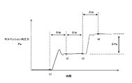
- FIG. 9 is a flowchart showing an example, and is a graph showing an example of the time change of the detection value of the suspension pressure sensor 39a of the dump truck 2 engaged in the loading operation.
- Each step in FIG. 8 is executed in the controller 40 of the dump truck 2 at a predetermined sampling period.
- step S110 the loading determination unit 52 determines whether or not a predetermined time ⁇ tp has elapsed from the start of the flowchart. If it is determined that the predetermined time ⁇ tp has not elapsed, the process returns to step S110 and continues. The elapsed time is monitored in step S110. On the other hand, when it is determined that the predetermined time ⁇ tp has elapsed, the process proceeds to step S111.
- step S111 pressure values output from the four suspension pressure sensors 39a to 39d are acquired.
- step S112 a difference ⁇ P between the pressure value in step S111 of each of the suspension pressure sensors 39a to 39d and the previous pressure value is calculated, and it is determined whether any one of the four differences is equal to or more than a predetermined value.
- predetermined value is a pressure value acquired in step S111 one control cycle before ( ⁇ tp before) and stored in step S115.
- the predetermined value in this case can be set to a value capable of determining whether or not the work object has been loaded into the loading platform 36 of the dump truck 2, and can be set, for example, as a pressure value that increases with the weight of the work object of half the bucket capacity.
- step S112 when any of the four differences ⁇ Pa- ⁇ Pd is equal to or greater than a predetermined value, it is determined that the work object has been loaded into the loading platform 36, and the process proceeds to step S113. If not, the process proceeds to step S115.
- step S113 the loading determination unit 52 calculates the weight (loading amount) M (second load) of the input work object. Assuming that the inner diameter of each of the suspensions 38a to 38d is Aa-Ad, and the gravitational acceleration is g, the weight M (second load) of the work target is expressed by the following equation (1).
- the loading determination unit 52 determines (loading determination) that loading of the work object onto the dump truck 2 by the hydraulic shovel 1 has been performed in step S114, and transmits and receives
- the unit 53 transmits the determination result (loading determination) and the loading amount M to the controller 21 of the hydraulic shovel 1 via the wireless transceiver 42, and the process proceeds to step S115.
- step S115 the loading determination unit 52 saves each suspension pressure acquired in this step S111 as the previous suspension pressure in the calculation of the next step S112, and the transmitting and receiving unit 53 uses the suspension pressure via the wireless transceiver 42. And sends it to the controller 21 on the hydraulic shovel 1 side. Thereafter, the process returns to the front of step S110, and the loading determination unit 52 stands by again until a predetermined time ⁇ tp elapses.
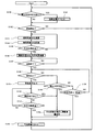
- FIG. 10 shows a method (first determination) for determining whether or not loading of the work object onto the dump truck 2 by the hydraulic shovel 1 has been performed by the transport determining unit 51 in the controller 21 on the hydraulic shovel 1 side.
- FIG. 11 is a flowchart showing the relationship between the detection value of the arm bottom pressure sensor 31 (arm cylinder bottom pressure) and the detection value of the bucket angle sensor 26 (arm-bucket relative angle) and the determination result by the conveyance determination unit 51. It is an example.
- the flowchart of FIG. 10 is executed in each controller 21 of the hydraulic shovel 1 at predetermined sampling intervals.
- the conveyance determination unit 51 monitors the output of the arm bottom pressure sensor 31 in step S120, and determines whether the threshold 1 has been exceeded from a state lower than the threshold 1 set in advance. Since the hydraulic shovel 1 extrudes the arm cylinder 17 and excavates, as shown in the lower graph of FIG. 11, the arm cylinder bottom pressure increases during the excavating operation, so the arm bottom pressure exceeds the threshold 1 in this embodiment. It is considered that the drilling operation has started at the right timing. When it is determined in step S120 that the arm bottom pressure is lower than the threshold 1 and the threshold 1 is exceeded, the transport determining unit 51 determines that the hydraulic shovel 1 has started the digging operation, and proceeds to step S121. Conversely, if the arm bottom pressure does not exceed the threshold 1 from the state of being lower than the threshold 1 (if the threshold 1 or lower is maintained), the process returns to step S120 and monitoring of the output of the arm bottom pressure sensor 31 is continued.
- step S121 the output of the arm bottom pressure sensor 31 is continuously monitored, and it is determined whether or not the threshold value 2 is exceeded from a state higher than the threshold value 2 set in advance.
- the arm cylinder bottom pressure decreases when the digging operation ends, so in the present embodiment, the digging operation ends at the timing when the arm bottom pressure falls below the threshold 2 and the transport operation starts I consider it to be. If it is determined in step S121 that the arm bottom pressure is higher than the threshold 2 and lower than the threshold 2 in step S121, the conveyance determining unit 51 determines that the hydraulic shovel 1 ends the digging operation and starts the conveyance operation (fourth The determination (part 1) is made, and the process proceeds to step S122.
- the transport determining unit 51 determines that the digging operation continues, and returns to step S121. Then, monitoring of the output of the arm bottom pressure sensor 31 is continued.
- threshold 1 With regard to the relationship between threshold 1 and threshold 2, in the example shown in FIG. 11, the relationship of threshold 1 ⁇ threshold 2 holds, but this is only an example, and the determination of the start and end of the excavation operation of hydraulic excavator 1 Any value can be set as far as possible. At that time, the magnitude relationship between the threshold 1 and the threshold 2 does not matter.
- step S122 the conveyance determination unit 51 outputs the determination that the conveyance operation has started to the outside, and the process proceeds to step S123.
- the load integration determination unit 55 is included in the output destination of the determination at this time.
- step S123 the conveyance determining unit 51 monitors the output of the bucket angle sensor 26, and determines whether the relative angle between the arm and the bucket (the angle formed by the arm 14 and the bucket 15) exceeds a preset threshold 3 or not.
- the hydraulic shovel 1 which completes the transportation operation and starts the loading operation operates to widen the angle between the arm 14 and the bucket 15 in order to discharge the soil (the object to be excavated) in the bucket 15. That is, as shown in the upper graph of FIG. 11, the relative angle between the arm 14 and the bucket 15 becomes large when transitioning from the carrying operation to the loading operation, so in this embodiment the relative angle between the arm 14 and the bucket 15 is the threshold 3 It is considered that the transport operation is finished and the loading operation is started at the timing when it exceeds.
- step S123 If it is determined in step S123 that the arm-bucket relative angle exceeds the threshold 3, the transport determining unit 51 determines that the hydraulic shovel 1 has finished the transport operation and has started the loading operation (the fourth determination ( 2)) and the process proceeds to step S124. Conversely, if it is determined that the arm-bucket relative angle does not exceed the threshold 3 (if the threshold 3 or less is maintained), the transport determining unit 51 determines that the transport operation is continuing, and before step S123 Then, the monitoring of the output of the bucket angle sensor 26 is continued.
- step S124 the transport determination unit 51 outputs a determination that the transport operation has ended (determination that the loading operation has started) to the outside, and returns to step S120.
- the output destination of the determination at this time includes the load integration determination unit 55 and the abnormality determination unit 58.
- FIG. 12 is a flowchart showing a method (fifth determination) of determining the presence or absence of an abnormality of the load measuring system of the present embodiment by the abnormality determining unit 58 in the controller 21 of the hydraulic shovel 1 side.
- the flowchart of FIG. 12 is executed in each controller 21 of the hydraulic shovel 1 at predetermined sampling intervals.
- step S130 the abnormality determination unit 58 first determines whether the loading operation determination received from the dump truck 2 (the result of the loading operation determination transmitted in step S106 of FIG. 6) is set as the loading operation. If it is determined that "loading operation” is set, the process proceeds to step S133, and if "unloading operation” is set, the process proceeds to step S131.
- the abnormality determination unit 58 determines whether or not a predetermined time ⁇ tw has elapsed from the start of the flowchart, and confirms whether there is no reception of the result of the loading operation determination.
- the predetermined time ⁇ tw in this case is a time longer than the execution cycle of the flowchart of FIG. 6 by the loading operation determination unit 57, that is, a time longer than the predetermined time ⁇ tv in step S100 of FIG.
- the value of ⁇ tw is not less than ⁇ tv and not more than twice the value of ⁇ tv. Since the controller 40 of the dump truck 2 transmits the result of the loading operation determination at a constant period ⁇ tv as shown in FIG.
- step S131 If it is determined in step S131 that the predetermined time ⁇ tw has not elapsed, the process returns to step S130, and in step S130, it is monitored again whether or not the result of the loading operation determination has been received. On the other hand, when it is determined that the predetermined time ⁇ tw has elapsed, the process proceeds to step S132.
- step S132 it is determined in the transport determination unit 51 whether or not it is determined that the hydraulic shovel 1 has finished the transport operation.
- the process returns to the front of step S130, and it is monitored again in step S130 whether or not the result of the loading operation determination has been received.
- the process proceeds to step S137, determines that the system has an abnormality, and outputs an abnormality determination.
- step S131 when it is determined in step S131 that the result of the loading operation determination has not been received for the predetermined period ⁇ tw, and it is determined in step S132 that the hydraulic shovel 1 has finished transporting, the hydraulic shovel 1 It can be determined that the loading is in progress but the communication between the two is not established. That is, when it is determined YES in step S132, it can be determined that there is an abnormality in the communication relationship.
- step S132 the start of the loading operation may be determined instead of the end of the transport operation.
- step S130 When the loading operation determination is set to "loading operation" in step S130, the output values of the suspension pressure sensors 39a to 39d transmitted from the controller 40 of the dump truck 2 in step S115 of FIG. 8 are abnormal. It is determined in step S133 whether there is any (fifth determination). Specifically, the average value of the pressure values of the four suspensions is calculated from the output values of the suspension pressure sensors 39a to 39d indicating the weight of the work object loaded in the dump truck 2, and the four pressures relative to the average value Deviations of the values are respectively calculated, and if all the four deviations are within the predetermined value, it is regarded that there is no abnormality in the suspension pressure sensors 39a to 39d, and the process proceeds to step S134.
- the four deviations include one having a predetermined value or more, it is determined that the system has an abnormality.
- one of the suspension pressure sensors 39a to 39d fails, the pressure value is not output normally, and the deviation of the output value from the non-failed sensor increases. Therefore, when it is determined NO in step S133, it can be determined that there is a possibility that the pressure sensors 39a to 39d are broken.
- step S134 the abnormality determination unit 58 determines that loading of the work object onto the dump truck 2 by the hydraulic shovel 1 has been performed (loading determination transmitted in step S114 of FIG. 8). It is determined whether it has been received from the controller 40 or not. If it is determined that the loading determination has been received, the process proceeds to step S135. If not, the process returns to step S130 to monitor again whether or not the loading determination has been received.
- step S135 the load value (first load) of the work object in the bucket 15 output from the load calculation unit 50 in step S146 of FIG. 14 described later and the loading determination unit 52 in step S114 of FIG.
- the output loading amount M (second load) is compared, and it is determined whether or not the deviation (weight deviation) between the two is within a predetermined value. If the weight deviation is within the predetermined value, it is determined in step S136 that the system is normal. On the other hand, when the weight deviation exceeds the predetermined value, it is determined in step S137 that there is an abnormality in the system. As described above, when NO is determined in step S135, it can be determined that there is a possibility that a problem has occurred in either the load calculation unit 50 of the hydraulic shovel 1 or the loading determination unit 52 of the dump truck 2.
- the determination result of the system abnormality based on the flowchart of FIG. 12 is stored in the controller 21 of the hydraulic shovel 1 and is referred to as appropriate by the controller 21 itself, another apparatus, or a computer. Even if the process is determined to be abnormal at step S137, if the process proceeds to step S136 after the dump truck 2 is replaced or the like, the determination result that the system is normal is stored.
- FIG. 13 is an explanatory view of a calculation method of the instantaneous load Ml of the work object in the bucket 15 by the load calculation unit 50 in the controller 21 on the hydraulic shovel 1 side.
- the torque acting around the pivot axis of the boom 13 the torque generated by the boom cylinder 16, the torque generated by the front work machine 12 by gravity and the turning centrifugal force, and the work object by gravity
- the load is calculated using the balance of the torque generated by the rotation centrifugal force.
- the thrust Fcyl of the boom cylinder 16 is calculated by multiplying each of the output signal of the boom bottom pressure sensor 29 and the output signal of the boom rod pressure sensor 30 by the pressure receiving area of the boom cylinder 16 and calculating the difference between them.
- the torque Tbm generated by the boom cylinder 16 is Lbm
- the direction of the thrust Fcyl of the boom cylinder 16, the line segment Lbm, and the thrust direction is the length of a line connecting the boom rotation shaft and the application point of the thrust Fcyl of the boom cylinder 16. It is calculated by the following equation (2) as the formed angle ⁇ bmcyl.
- Tbm Fcyl Lbm sin ( ⁇ bmcyl) (2)
- the torque Tgfr generated by gravity of the front working machine 12 is Mfr
- the gravity acceleration of the front working machine 12 is g
- the length of the boom rotation axis and the front gravity center is Lfr
- Tgfr Mfr ⁇ g ⁇ Lfr (3)
- the torque Tcfr generated by the front working machine 12 by the turning centrifugal force is calculated by the following equation (4), where the turning angular velocity is ⁇ , and the angle formed by the line connecting the boom rotation axis and the front center of gravity and the horizontal plane is ⁇ fr.
- Tcfr Mfr ⁇ Lfr ⁇ ⁇ 2 ⁇ sin ( ⁇ fr) (4) Mfr, Lfr and ⁇ fr are output from the position of the center of gravity and weight of boom 13, arm 14 and bucket 15 set in advance, and from boom angle sensor 24, arm angle sensor 25, bucket angle sensor 26 and inclination angle sensor 28 It is calculated from the angle signal to be
- the torque Tgl generated by gravity of the work object is calculated by the following equation (5), where the instantaneous load of the work object is Ml and the length of the boom rotation axis and the bucket center of gravity is Ll.
- Tgl Ml ⁇ g ⁇ Ll (5)
- the torque Tcl generated by the work object by the turning centrifugal force is calculated by the following equation (6), where the angle formed by the line connecting the boom rotation axis and the center of gravity of the work object and the horizontal plane is ⁇ l.
- FIG. 14 is a flowchart of processing executed by the load calculation unit 50, the load integration determination unit 55, and the load integration unit 56 in the controller 21 of the hydraulic excavator 1 side.
- the load calculation unit 50 determines the load (first load) of the work object in the bucket being transported
- the load integration determination unit 55 determines the load (first load).
- a method of outputting the load weight by determining whether or not to integrate (third determination) and integrating the load by the load integration unit 56 will be described.
- the flowchart of FIG. 14 is executed at a predetermined sampling cycle in the controller 21 on the hydraulic shovel 1 side.
- step S140 the load integration unit 56 determines whether or not the setting of the loading operation determination output from the dump truck 2 at a constant cycle ⁇ tv in step S106 of FIG. 6 has been switched. If it is determined that there is no switch in the loading operation determination, the process proceeds to step S142. If it is determined that the switch is performed, the load weight of the dump truck 2 is reset in step S141, and the process proceeds to step S142. By resetting the loading weight at the timing when the loading operation is switched to the non-loading operation, the load of the work object can be integrated only during the loading operation of the dump truck 2.
- step S142 the load calculation unit 50 monitors whether or not the conveyance determination unit 51 has output a start determination of the conveyance operation. If the start determination of the transport operation is output, the process proceeds to step S143. If not, the process returns to step S140 to monitor the output of the loading operation determination unit 57 (setting of the loading operation determination).
- step S143 the load calculation unit 50 calculates the instantaneous load Ml of the work object by performing calculations according to equations (2) to (8), and in step S144, records the instantaneous load Ml in the controller 21 and step S145. Go to
- step S145 the load calculation unit 50 determines whether or not a predetermined time has elapsed from the time of output of the start determination of the transportation operation (when YES is determined in step S142). If it is determined that the predetermined time has not elapsed, the process returns to the front of step S143, and steps S143 and S144 are executed again. By repeating steps S143 and S144 for a predetermined time, a plurality of instantaneous loads M1 calculated within the predetermined time can be recorded. On the other hand, if it is determined that the predetermined time has elapsed, the process proceeds to step S146. In step S146, the load calculation unit 50 calculates an average load of the plurality of instantaneous loads M1 recorded within the predetermined time, and the average load is used as a load value (first load) of the work object, and the process proceeds to step S147.
- step S147 the load integration availability determination unit 55 monitors whether or not the conveyance determination unit 51 has output a determination on the end of the conveyance operation. If it is determined that the transport operation end determination is not output, the process returns to the front of step S147, and monitoring of the transport operation end determination is continued. On the other hand, when it is determined that the transport operation end determination is output, it is considered that the loading operation by the hydraulic shovel 1 has started, and the process proceeds to step 148. In step S147, instead of the determination of the end of the transport operation, the determination of the start of the loading operation may be monitored.
- step S148 the load integration determination unit 55 determines whether the abnormality determination unit 58 determines that an abnormality has been made. That is, the determination is performed with reference to the result of the abnormality determination stored in the controller 21.
- the process proceeds to step S149, and if the abnormality determination is performed (that is, the abnormality determination is stored), the process proceeds to step S151.
- step S149 the load accumulation determination unit 55 determines that loading of the work object onto the dump truck 2 by the hydraulic shovel 1 has been performed (loading determination transmitted in step S114 of FIG. 8). It is determined whether or not it has been received from the controller 40 of If it is determined that the loading determination has been received, the load integration unit 56 integrates the average load calculated in step S145 into the previous load weight (integrated load) in step S154, and the process proceeds to step S155. On the other hand, if it is determined in step S149 that no loading determination has been received, the process proceeds to step S150.
- step S150 the load integration availability determination unit 55 determines whether or not a predetermined time ⁇ T has elapsed from the determination of the end of the transport operation in step S147.
- a predetermined time ⁇ T (1) from the time required for the loading operation of the hydraulic shovel 1 to (2) from the time required for a series of operations consisting of digging, carrying, loading and reaching during the loading operation of the hydraulic shovel 1 You can set any time between them.
- the predetermined time ⁇ T may be input and determined by the operator via the input device 23B in accordance with the tendency of the required time of each operator regarding the loading operation. If it is determined in step S150 that the predetermined time ⁇ T has not elapsed, the process returns to step S148 to monitor abnormality determination and loading determination again.
- step S155 As a specific example in the case of proceeding from step S150 to step S155, although the hydraulic shovel 1 dumps the bucket 15, there is no loading platform 36 for the dump truck 2 therebelow, and the work object to the dump truck 2 There are cases where loading has failed.
- the load integration possibility determination unit 55 inquires the operator of the necessity for integration along with a warning display notifying the operator that the load can not be automatically integrated due to a system abnormality in step S151.
- the display unit 23A is instructed to output an inquiry display to be displayed, whereby a warning display and an inquiry display are displayed on the display unit 23A (for the inquiry display, refer to the inquiry display portion 81 in FIG. 15 described later).
- an instruction of integration required is input through the input device 23B.
- the load integration availability determination unit 55 determines whether or not an instruction requiring integration (which may be referred to as “integration instruction” in this document) is input from the operator via the input device 23B.
- integration instruction an instruction requiring integration
- the load integration unit 56 integrates the average load calculated in step S145 into the load weight (accumulated load) obtained so far (step S154), and proceeds to step S155.
- the process proceeds to step S153, and it is determined whether a predetermined time has elapsed from the warning output of step S151.
- step S153 If it is determined in step S153 that the predetermined time has not elapsed, the process returns to step S152 to monitor again the presence or absence of the input of the integration instruction. On the other hand, when it is determined that the predetermined time has elapsed, the process skips step S154 and proceeds to step S155.
- step S155 the load calculation unit 50 resets the average load calculated in step S146 and returns to the step before step S140.
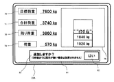
- FIG. 15 is an external view of a display screen (output screen) of the display device 23A.
- the display method of the load measurement result in the load measurement system of this embodiment and the method of integration execution instruction when there is an abnormality in the system will be described using FIG.
- the display device 23A is configured by a touch panel, and the display screen of the display device 23A displays a target load display unit 70 that displays the target loading weight (target load value) of the dump truck 2, and the bucket calculated in S146 of FIG.
- Internal load value display unit 72 for displaying the load value (average load value of instantaneous load Ml) of the work object in 15 and the integrated value of the load value of the work object in the bucket 15 calculated in step S154 (dump Of the total load display section 71 displaying the integrated weight of the truck 2), the value displayed on the target load display section 70 (target load weight), and the value displayed on the total load display section 71 (integrated value of load values)
- Remaining load display unit 72 for displaying the difference
- integration bar display unit 75 for displaying the accumulated load value history of the work object as a numerical value and a vertical bar graph (integration bar)
- step S15 Display of the query is a query display section 81 displayed.
- the value of the in-bucket load display unit 72 is updated to the latest value calculated in step S146 of FIG. 14 and is updated to 0 when reset in step S155.
- the value of the total load display unit 71 and the display of the integration bar display unit 75 are updated to the latest values when step S154 is performed, and are updated to 0 when reset in step S141.
- the inquiry display unit 81 displays an inquiry display 83 inquiring of the operator whether or not the loading is necessary in step S151.
- an integration instruction input unit 82 which is a button pressed when the operator desires integration, is displayed together with the inquiry display 83.
- the load integration determination unit 55 determines in step S152 that the integration instruction has been input.
- the integration instruction input unit 82 is not pressed, the integration in step S154 is not performed. In the example of FIG. 15, the remaining time (5 seconds in FIG.
- step 15 from the timing at which the warning display is output in step S151 to the elapse of the predetermined time in step S153 is referred to It is configured to display on the display unit 81, and when the remaining time reaches zero (ie, when the predetermined time in step S153 has elapsed), the display in the inquiry display unit 81 disappears.
- the loading operation determination unit 57 of the controller 40 determines the loading operation. It changes during the loading operation from the non-loading operation (FIG. 6: steps S102, S103) and transmits the result to the controller 21 of the hydraulic shovel 1 (FIG. 6: step S106).
- the controller 21 of the hydraulic shovel 1 having received the loading work judgment result recognizes that the loading work judgment result has been switched, resets the loading weight (FIG. 14: steps S140 and 141), and the hydraulic shovel 1 carries out the transport operation. Monitoring of whether or not to start is started (FIG. 14: step 142).
- the load associated with the digging causes the bottom pressure of the arm cylinder 17 to exceed the threshold 1 and then the digging operation is completed and the load is reduced.
- the bottom pressure is below threshold 2.
- the conveyance determination unit 51 of the controller 21 outputs a determination indicating that the hydraulic shovel 1 has started the conveyance operation (FIG. 10: step S122).
- the load integration unit 56 of the controller 21 repeatedly calculates and records the instantaneous load Ml of the work object in the bucket 15 for a predetermined time, and the predetermined time
- the average load value of the instantaneous load Ml calculated in is taken as the load value of the work object (FIG. 14: steps S143-146). That is, the calculation of the load value of the work object is performed during the transportation operation of the hydraulic shovel 1.
- the hydraulic shovel 1 having moved the bucket 15 to the upper side of the loading platform of the dump truck 2 by the transporting operation starts the dumping operation of the bucket 15 to start the loading operation.
- the arm-bucket relative angle exceeds the threshold value 3
- the conveyance determination unit 51 of the controller 21 outputs a determination indicating that the hydraulic shovel 1 has completed the conveyance operation (FIG. 10: step S124).
- the fact that the transport determination unit 51 outputs the end determination of the transport operation in this way indicates that the hydraulic shovel 1 has started the loading operation, and the hydraulic shovel 1 will soon be the work object on the loading platform 36 of the dump truck 2 Indicates that it will be injected.
- the controller 21 of the hydraulic shovel 1 receives the loading determination input from the controller 40 of the dump truck 2 using the output of the transport operation determination from the transport determining unit 51 as a trigger when the determination result by the abnormality determining unit 58 is normal determination. It is started to monitor whether or not it is received (FIG. 14: step S149).
- the controller 40 Sends a loading determination to the controller 21 of the hydraulic shovel 1 (FIG. 8: step S114).
- the controller 21 When the controller 21 confirms the reception of the loading determination from the dump truck 2, the controller 21 integrates the average load value of the instantaneous load Ml calculated above to calculate the loading weight of the dump truck 2.
- the loading weight at the first loading is the average load value.
- the calculation result of the load weight is displayed on the total load display section 71 of the display device 23A of the hydraulic shovel 1 (FIG. 15). Also in the second and subsequent loading operations, if loading from the hydraulic shovel 1 to the dump truck 2 is normally performed, the same processing as described above is repeated, and the load value of the work object calculated by the load calculation unit 50 is It is integrated to the load weight.
- the transport determination unit Even if the predetermined time ⁇ T has elapsed since the determination of the end of the transport operation from 51, the loading determination is not transmitted from the controller 40 of the dump truck 2.
- the controller 21 of the hydraulic shovel 1 carries out the loading operation of the hydraulic shovel 1, but considers that loading on the dump truck 2 has failed for some reason, and the load of the work object associated with the loading operation this time The integration of the values is canceled, the load value of the work object calculated during the transport operation is reset, and it is waited until the next start judgment of the transport operation is output.
- step S137 abnormality determination unit 58 of the controller 21 of the hydraulic excavator 1
- the flow until the end of the carrying operation of the hydraulic shovel 1 is the same as in the case of normality determination, so the description will be omitted.
- abnormality judgment unit 58 When the judgment result by the controller 21 (abnormality judgment unit 58) of the hydraulic shovel 1 is abnormality judgment, communication abnormality between the two controllers 21, 40, abnormality of the suspension pressure sensor 39 of the dump truck 2, or calculation abnormality of the load value there is a possibility.
- a warning display and an inquiry display 83 are output to the display device 23A (FIG. 14: step S151).
- the operator of the hydraulic shovel 1 can be made aware that a system abnormality has occurred and the integrated value of the load value of the work object can not be calculated automatically.
- the integration instruction input unit 82 is displayed on the display device 23A together with the inquiry display 83.
- the operator of the hydraulic shovel 1 inputs an integration instruction to the controller 21 via the integration instruction input unit 82.
- the controller 21 integrates the average load value of the instantaneous load Ml previously calculated in the same manner as in the case of the normality determination to calculate the loading weight of the dump truck 2.
- the load weight can be calculated.
- each of the controller 40 (loading determination unit 52) of the dump truck 2 and the controller 21 (transport determining unit 51) of the hydraulic shovel 1 It is determined whether the loading has been performed, and the controller 21 (load integration availability determination unit 55) of the hydraulic shovel 1 determines the availability of integration of the load value of the work object in the bucket based on both determination results.
- the controller 21 (load integration unit 56) of the hydraulic excavator 1 integrates the load value based on the determination result.
- the load value integration instruction is manually made only in the case of the system abnormality. You can reduce the operation burden of In addition, with this configuration, integration of load values can be continued even when an abnormality occurs.
- the present invention is not limited to the above-described embodiment, and includes various modifications within the scope of the present invention.
- the present invention is not limited to the one provided with all the configurations described in the above embodiment, but also includes one in which a part of the configuration is deleted.
- part of the configuration according to one embodiment can be added to or replaced with the configuration according to another embodiment.
- the determination method of the loading operation of the dump truck 2 is not limited to the method shown in FIG. 6 and FIG. FIG. 16 and FIG. 17 are explanatory views of a system that performs the loading work determination method of the dump truck 2 different from the above embodiment.
- FIG. 16 shows the system configuration of the load measuring system
- FIG. 17 is an explanatory view of the method of determining the loading operation of the dump truck 2 by the system of FIG.
- the dump truck 2 includes a GPS antenna 38.
- the controller 40 includes a transport machine position calculation unit 66 that calculates the absolute position of the dump truck 2 based on an input signal from the GPS antenna 38.
- the vehicle position calculated by the transport machine position calculation unit 66 is configured to be transmitted.
- the hydraulic shovel 1 also has a GPS antenna 38, and the controller 21 has a loading machine position calculation unit 65 for calculating the absolute position of the hydraulic shovel 1 based on an input signal from the GPS antenna 38, and loading machine position calculation
- the loading work determination unit 57 that determines the loading work state of the dump truck 2 based on the position information (relative distance) of the hydraulic shovel 1 and the dump truck 2 input from the unit 65 and the transport machine position calculation unit 66 is provided.
- the loading operation determination unit 57 sets the loading operation determination as loading operation when it is determined that the dump truck 2 is present at a position within a predetermined distance indicated by a broken line from the hydraulic shovel 1 as shown in FIG. If it is determined that the dump truck 2 is present at a position separated from the predetermined distance, the loading operation determination is set as non-loading operation. Even if the system is configured as described above, the same effect as that of the above embodiment can be exhibited.
- step S150 when YES is determined in step S150, the process may be configured to proceed to step S151 instead of proceeding to step S155.
- the process after step S151 in this case is as shown in FIG. If YES is determined in step S150, it is considered that the loading on the dump truck 2 has failed. Therefore, by displaying the warning display and the inquiry display on the display device 23A, the operator is prompted to input the accumulation instruction after the hydraulic shovel 1 performs the loading again. According to this configuration, the operator can recognize that the integration is interrupted due to the loading failure, and return to the state where the automatic integration before the loading failure can be triggered by the integration instruction. can do.
- step S 151 of FIG. 14 in the present embodiment, when abnormality determination is performed, it has been described that warning display and inquiry display 83 are performed on the display device 23A regardless of the cause. There is a possibility that the load value of the work object has an error if there is an abnormality in (in particular, it is determined as NO in step S135 of FIG. 12). Therefore, in this case, the system may be configured to perform only the abnormality display without performing the inquiry display 83, and may prevent the erroneous load value from being integrated by the operator's integration instruction.
- the abnormality determination unit 58 is provided in the controller 21 of the hydraulic excavator 1 in the above embodiment, this can be omitted.
- the process proceeds to step S149 when YES is determined in step S148 of the flowchart of FIG. 14, and the process is returned to step S149 when NO is determined in step S150. Just do it.
- the configuration of the load measurement system of the present invention is not limited to that shown in FIG.
- the loading determination unit 52 does not have to be mounted in the controller 40 of the dump truck 2 and inputs signals of the suspension pressure sensors 39a to 39d to the transmitting and receiving unit 53 to directly transmit the hydraulic excavator 1 from the wireless transceiver 42
- the controller 21 of the hydraulic shovel 1 may execute the processing corresponding to the arithmetic processing performed by the loading determination unit 52 by transmitting the information.
- the calculation of the instantaneous load Ml is not limited to the model shown in FIG. 13, and an arithmetic expression different from that described above may be used.
- the instantaneous load may be calculated using the equation of motion of the front working unit 12 configured by the boom 13, the arm 14, and the bucket 15.
- the method of calculating the load value of the work object is not limited to the method shown in FIG.
- the period during which the load is averaged may be determined using the magnitude of the turning angular velocity or the position of the bucket 15.
- the loading determination of the dump truck 2 is not limited to the contents shown in FIGS. 8 and 9.
- an acceleration sensor is attached to the vessel 36 or the vehicle body, and a change in acceleration in the vertical direction that occurs when the work object is thrown into the vessel 36 is detected by the acceleration sensor to output a loading determination. It is also good.
- the display content of the display device 23A is not limited to FIG.
- the ratio of the integrated load to the dump truck capacity may be displayed as a percentage, or a portion may be provided on the display screen in which the history of the past loading amount (loading weight) is arranged and displayed.
- the components of the controller 40 and the controller 21 and the functions and execution processes of the components are realized by hardware (for example, designing logic for executing each function by an integrated circuit). You may. Further, the configuration according to the controllers 40 and 21 may be a program (software) in which each function according to the configuration of the controllers 40 and 21 is realized by being read and executed by an arithmetic processing unit (for example, a CPU). .
- the information related to the program can be stored, for example, in a semiconductor memory (flash memory, SSD, etc.), a magnetic storage device (hard disk drive, etc.), a recording medium (magnetic disk, optical disc, etc.), and the like.
- Carrier bed 38 ... Suspension, 39 ... Suspension pressure sensor, 40 ... controller (transporter side controller), 41 ... display device, 42 ... wireless transmission Receiver, 43: Vehicle speed sensor, 50: Load calculation unit, 51: Transport determination unit, 52: Load determination unit, 53: Transmission and reception unit, 54: Transmission and reception unit, 55: Load integration availability determination unit, 56: Load integration unit , 57 ... loading operation determination unit, 58 ... abnormality determination unit, 70 ... target load display unit, 71 ... total load display unit, 72 ... load display unit, 81 ... inquiry display unit, 82 ... integration instruction input unit, 83 ... Display inquiry
Landscapes
- Engineering & Computer Science (AREA)
- Mining & Mineral Resources (AREA)
- Civil Engineering (AREA)
- General Engineering & Computer Science (AREA)
- Structural Engineering (AREA)
- Physics & Mathematics (AREA)
- General Physics & Mathematics (AREA)
- Mechanical Engineering (AREA)
- Operation Control Of Excavators (AREA)
- Component Parts Of Construction Machinery (AREA)
Abstract
Description
図1は本実施形態に係る油圧ショベルの側面図であり,図2は本実施形態に係るダンプトラックの側面図である。
図5は本実施形態の荷重計測システムのシステム構成図であり,コントローラ40とコントローラ21の内部にはそれぞれの機能をブロック図で示している。
ダンプトラック2側のコントローラ40は,サスペンション圧センサ39a,39b,39c,39dおよび車速センサ43の信号を入力とし,これらを基に算出した情報(例えば後述の積込判定と積込作業判定)を無線送受信機42を介してショベル側のコントローラ21に送信できるように構成されている。
図6はダンプトラック2側のコントローラ40における積込作業判定部57が,ダンプトラック2が積込作業に従事しているか否かを判定する方法(第6の判定)を示すフローチャートであり,図7は車速センサ43の検出値と積込作業判定部57による判定結果の関係を示すグラフの一例である。
図8はダンプトラック2側のコントローラ40の積込判定部52が,油圧ショベル1によるダンプトラック2への作業対象物の積込が行われたか否かという判定する方法(第2の判定)を示すフローチャートであり,図9は積込作業に従事しているダンプトラック2のサスペンション圧センサ39aの検出値の時間変化の一例を示すグラフである。
ステップS113で積込量Mを演算したら,積込判定部52はステップS114で油圧ショベル1によるダンプトラック2への作業対象物の積込が行われたという判定(積込判定)をし,送受信部53は無線送受信機42を介してその判定結果(積込判定)と積込量Mを油圧ショベル1側のコントローラ21に送信し,ステップS115に進む。
図10は油圧ショベル1側のコントローラ21における運搬判定部51が,油圧ショベル1によるダンプトラック2への作業対象物の積込が行われたか否かを判定する方法(第1の判定)を示すフローチャートであり,図11はアームボトム圧センサ31の検出値(アームシリンダボトム圧力)及びバケット角度センサ26の検出値(アーム-バケット相対角度)と運搬判定部51による判定結果の関係を示すグラフの一例である。
図12は油圧ショベル1側のコントローラ21における異常判定部58が本実施形態の荷重計測システムの異常の有無を判定する方法(第5の判定)を示すフローチャートである。
図13は油圧ショベル1側のコントローラ21における荷重演算部50によるバケット15内の作業対象物の瞬時荷重Mlの演算方法の説明図である。本実施形態では,ブーム13の回動軸周りに作用するトルクであって,ブームシリンダ16が発生するトルクと,フロント作業機12が重力と旋回遠心力により発生するトルクと,作業対象物が重力と旋回遠心力により発生するトルクの釣合を利用して荷重を算出する。
フロント作業機12が重力により発生するトルクTgfrは,フロント作業機12の重心重量をMfr,重力加速度をg,ブーム回動軸とフロント重心までの前後方向の長さをLfrとして以下の式(3)で算出される。
フロント作業機12が旋回遠心力により発生するトルクTcfrは,旋回角速度をω,ブーム回動軸とフロント重心を結ぶ線分と水平面が成す角度をθfrとして以下の式(4)で算出される。
なお,Mfr,Lfr,θfrは予め設定されたブーム13,アーム14,バケット15のそれぞれの重心位置,重量と,ブーム角度センサ24,アーム角度センサ25,バケット角度センサ26,傾斜角度センサ28から出力される角度信号から算出される。
作業対象物が旋回遠心力により発生するトルクTclは,ブーム回動軸と作業対象物の重心を結ぶ線分と水平面が成す角度をθlとして以下の式(6)で算出される。
式(1)から(5)の釣合いを変形して作業対象物の瞬時荷重Mlに関して展開すると,瞬時荷重Mlは以下の式(7)で算出される。
(Ll・(g+ω2・sin(θl))) …(7)
式(2)から(8)による荷重の演算は,センサのノイズや油圧回路の特性などにより運搬中常に一定の値を出力できないので,油圧ショベル1が運搬動作中の所定期間に算出した瞬時荷重Mlを平均化して,作業対象物の荷重(第1の荷重)を確定する。
図14は油圧ショベル1側のコントローラ21における荷重演算部50,荷重積算可否判定部55及び荷重積算部56が実行する処理のフローチャートである。ここでは図14を用いて,荷重演算部50が運搬中のバケット内の作業対象物の荷重(第1の荷重)を確定し,荷重積算可否判定部55がその荷重(第1の荷重)を積算するか否か判定し(第3の判定),荷重積算部56が荷重を積算することで積載重量を出力する方法について説明する。
図15は表示装置23Aの表示画面(出力画面)の外観図である。図15を用いて本実施形態の荷重計測システムにおける荷重計測結果の表示方法と,システムに異常がある場合の積算実施指示の方法について説明する。
(1)正常判定の場合
次に上記のように構成される荷重計測システムの動作を説明する。はじめに油圧ショベル1のコントローラ21の異常判定部58で正常判定(図11:ステップS136)がされている場合について説明する。
次に油圧ショベル1のコントローラ21の異常判定部58で異常判定(図11:ステップS137)がされている場合について説明する。この場合も,油圧ショベル1の運搬動作の終了までの流れは正常判定のとき同じなので説明は省略する。
以上のように,本実施形態では,ダンプトラック2のコントローラ40(積込判定部52)と油圧ショベル1のコントローラ21(運搬判定部51)のそれぞれが油圧ショベル1からダンプトラック2に対して積込が行われたか否かを判定し,その両方の判定結果に基づいて油圧ショベル1のコントローラ21(荷重積算可否判定部55)がバケット内の作業対象物の荷重値の積算の可否を判定し,その判定結果に基づいて油圧ショベル1のコントローラ21(荷重積算部56)が当該荷重値の積算することとした。このようにシステムを構成すると,油圧ショベル1からダンプトラック2に作業対象物が積み込まれたことが誤りなく検出されるので,ダンプトラック2への積込量(ダンプトラック2の積載重量)を正確に算出できる。
なお,本発明は,上記の実施の形態に限定されるものではなく,その要旨を逸脱しない範囲内の様々な変形例が含まれる。例えば,本発明は,上記の実施の形態で説明した全ての構成を備えるものに限定されず,その構成の一部を削除したものも含まれる。また,ある実施の形態に係る構成の一部を,他の実施の形態に係る構成に追加又は置換することが可能である。
Claims (6)
- 油圧ポンプから吐出される圧油によって駆動される油圧シリンダと,前記油圧シリンダによって駆動される作業機と,前記作業機により運搬機械に積み込まれた作業対象物の積載重量を演算するコントローラとを備えた油圧ショベルにおいて,
前記コントローラは,
前記作業機の姿勢に基づいて前記油圧ショベルによる前記運搬機械への作業対象物の積込が行われたか否かを判定する第1の判定を行い,
前記油圧シリンダの推力と前記第1の判定の判定結果とに基づいて前記油圧ショベルにより前記運搬機械へ積込まれた作業対象物の荷重である第1の荷重を演算し,
前記運搬機械に備えられた運搬機械側コントローラから送信された前記油圧ショベルによる前記運搬機械への作業対象物の積込が行われたか否かを判定する第2の判定の判定結果と前記第1の判定の判定結果とに基づいて前記第1の荷重を積算するか否かを判定する第3の判定を行い,
前記第3の判定により前記第1の荷重を積算すると判定された場合に前記第1の荷重を積算することで前記運搬機械の積載重量を演算すること
を特徴とする油圧ショベル。 - 請求項1の油圧ショベルにおいて,
前記コントローラは,前記第1の判定により前記運搬機械への作業対象物の積込が行われたと判定された時から所定時間内に,前記第2の判定により前記運搬機械への作業対象物の積込が行われたという判定結果を前記運搬機械側コントローラから受信した場合,前記第1の荷重を積算すること
を特徴とする油圧ショベル。 - 請求項1の油圧ショベルにおいて,
前記コントローラは,
前記作業機の姿勢に基づいて,前記運搬機械に対する前記油圧ショベルの運搬動作の開始と終了を判定する第4の判定を行い,
前記第4の判定により前記運搬動作の開始から終了までの間の前記油圧シリンダの推力に基づいて前記第1の荷重を演算し,
前記第4の判定により前記運搬動作が終了したと判定され,かつ,前記第2の判定により前記油圧ショベルによる前記運搬機械への作業対象物の積込が行われたと判定されたという判定結果を前記運搬機械側コントローラから受信した場合,前記第1の荷重を積算すること
を特徴とする油圧ショベル。 - 請求項1の油圧ショベルにおいて,
操作者からの指示を入力するための入力装置と,所定の情報を表示するための表示装置とをさらに有し,
前記コントローラは,
前記運搬機械側コントローラから送信される前記運搬機械に積み込まれた作業対象物の重量に基づいて前記運搬機械の異常の有無を判定する第5の判定を行い,
前記第5の判定により前記運搬機械に異常が有ると判定した場合,前記表示装置を介して前記異常の発生を報知し,前記運搬機械への作業対象物の積込が行われたことが前記入力装置を介して入力された場合に前記第1の荷重を積算すること
を特徴とする油圧ショベル。 - 請求項1の油圧ショベルにおいて,
操作者からの指示を入力するための入力装置と,所定の情報を表示するための表示装置とをさらに有し,
前記コントローラは,
前記運搬機械側コントローラで演算された前記油圧ショベルにより前記運搬機械へ積込まれた作業対象物の荷重である第2の荷重と前記第1の荷重との差分が所定値を越える場合、前記油圧ショベルと前記運搬機械のいずれかに異常が有ると判定し,
前記油圧ショベルと前記運搬機械のいずれかに異常が有ると判定した場合,前記表示装置を介して前記異常の発生を報知し,前記運搬機械への作業対象物の積込が行われたことが前記入力装置を介して入力された場合に前記第1の荷重を積算すること
を特徴とする油圧ショベル。 - 請求項1の油圧ショベルにおいて,
前記コントローラは,前記運搬機械から送信される,前記運搬機械の走行速度に基づいて前記運搬機械が前記油圧ショベルによる作業対象物の積込作業に従事しているか否かを判定する第6の判定を行い、前記第6の判定結果が切り替わった場合に,前記作業対象物の荷重の積算値をリセットすること
を特徴とする油圧ショベル。
Priority Applications (4)
| Application Number | Priority Date | Filing Date | Title |
|---|---|---|---|
| CN201880013791.8A CN110382789B (zh) | 2017-09-21 | 2018-09-21 | 液压挖掘机 |
| US16/493,010 US11454005B2 (en) | 2017-09-21 | 2018-09-21 | Hydraulic excavator |
| EP18858189.6A EP3686357B1 (en) | 2017-09-21 | 2018-09-21 | Hydraulic shovel |
| KR1020197025128A KR102234963B1 (ko) | 2017-09-21 | 2018-09-21 | 유압 셔블 |
Applications Claiming Priority (2)
| Application Number | Priority Date | Filing Date | Title |
|---|---|---|---|
| JP2017181789A JP6745254B2 (ja) | 2017-09-21 | 2017-09-21 | 油圧ショベル |
| JP2017-181789 | 2017-09-21 |
Publications (1)
| Publication Number | Publication Date |
|---|---|
| WO2019059383A1 true WO2019059383A1 (ja) | 2019-03-28 |
Family
ID=65811383
Family Applications (1)
| Application Number | Title | Priority Date | Filing Date |
|---|---|---|---|
| PCT/JP2018/035212 Ceased WO2019059383A1 (ja) | 2017-09-21 | 2018-09-21 | 油圧ショベル |
Country Status (6)
| Country | Link |
|---|---|
| US (1) | US11454005B2 (ja) |
| EP (1) | EP3686357B1 (ja) |
| JP (1) | JP6745254B2 (ja) |
| KR (1) | KR102234963B1 (ja) |
| CN (1) | CN110382789B (ja) |
| WO (1) | WO2019059383A1 (ja) |
Cited By (1)
| Publication number | Priority date | Publication date | Assignee | Title |
|---|---|---|---|---|
| CN113654630A (zh) * | 2021-07-30 | 2021-11-16 | 深圳市中金岭南有色金属股份有限公司凡口铅锌矿 | 矿物重量测量方法、装置、设备及存储介质 |
Families Citing this family (10)
| Publication number | Priority date | Publication date | Assignee | Title |
|---|---|---|---|---|
| US11125605B2 (en) * | 2017-03-03 | 2021-09-21 | Cnh Industrial America Llc | System and method for estimating implement load weights for a work vehicle |
| JP6868938B2 (ja) * | 2017-08-24 | 2021-05-12 | 日立建機株式会社 | 建設機械の荷重計測システム |
| US11498785B2 (en) * | 2019-01-30 | 2022-11-15 | Caterpillar Inc. | System and method of automated clean out of carryback in surface haulage |
| JP7253949B2 (ja) * | 2019-03-25 | 2023-04-07 | 株式会社小松製作所 | 作業機械、システムおよび作業機械の制御方法 |
| JP7300408B2 (ja) * | 2020-02-21 | 2023-06-29 | 日立建機株式会社 | 作業機械および制御システム |
| CN116438356B (zh) * | 2020-12-07 | 2026-04-21 | 住友重机械工业株式会社 | 施工机械及施工机械用控制装置 |
| CN117043421A (zh) * | 2021-03-29 | 2023-11-10 | 住友建机株式会社 | 挖土机的显示装置、挖土机及挖土机的支援装置 |
| CN113982060A (zh) * | 2021-11-12 | 2022-01-28 | 博雷顿科技有限公司 | 一种电动装载机双电机控制系统及方法 |
| JP7786145B2 (ja) * | 2021-11-17 | 2025-12-16 | コベルコ建機株式会社 | 作業システム |
| JP7807956B2 (ja) * | 2022-03-23 | 2026-01-28 | 日立建機株式会社 | 作業機械 |
Citations (6)
| Publication number | Priority date | Publication date | Assignee | Title |
|---|---|---|---|---|
| JPH1037254A (ja) * | 1996-07-29 | 1998-02-10 | Shin Caterpillar Mitsubishi Ltd | 作業機械における負荷重量計測装置 |
| JP3787046B2 (ja) | 1999-09-17 | 2006-06-21 | 日立建機株式会社 | 油圧ショベルの作業量モニタ装置 |
| JP3830151B2 (ja) * | 2001-10-18 | 2006-10-04 | 日立建機株式会社 | 油圧ショベルの作業量検出装置及び作業量検出方法並びに作業量検出結果表示装置 |
| JP2011516755A (ja) * | 2008-03-07 | 2011-05-26 | キャタピラー インコーポレイテッド | 適応型ペイロード監視システム |
| JP2012215495A (ja) * | 2011-04-01 | 2012-11-08 | Hitachi Constr Mach Co Ltd | 荷重計測装置 |
| JP2015040422A (ja) * | 2013-08-22 | 2015-03-02 | 日立建機株式会社 | 建設機械の表示装置 |
Family Cites Families (14)
| Publication number | Priority date | Publication date | Assignee | Title |
|---|---|---|---|---|
| AU2982584A (en) | 1983-06-17 | 1984-12-20 | Prgromet, L.S. | Excavator bucket load weigher |
| JPH0610378A (ja) | 1992-06-26 | 1994-01-18 | Komatsu Ltd | 掘削積込機の作業量検出装置 |
| US5528498A (en) * | 1994-06-20 | 1996-06-18 | Caterpillar Inc. | Laser referenced swing sensor |
| US6157889A (en) * | 1999-09-16 | 2000-12-05 | Modular Mining Systems, Inc. | Load distribution system for haulage trucks |
| JP2008240461A (ja) * | 2007-03-28 | 2008-10-09 | Komatsu Ltd | 過積載防止システムおよび過積載防止方法 |
| JP5419998B2 (ja) * | 2010-01-22 | 2014-02-19 | 日立建機株式会社 | 積載案内システム |
| JP2012036645A (ja) * | 2010-08-06 | 2012-02-23 | Ohbayashi Corp | 積込量管理システム及び積込量管理方法 |
| US8833861B2 (en) | 2010-12-03 | 2014-09-16 | Caterpillar Inc. | Loading analysis system and method |
| WO2012133410A1 (ja) * | 2011-03-31 | 2012-10-04 | 日立建機株式会社 | 運搬機械の位置調整支援システム |
| WO2013065415A1 (ja) | 2011-11-04 | 2013-05-10 | 株式会社小松製作所 | 積載システム及び運搬機 |
| EP3985184B1 (en) * | 2015-08-24 | 2025-10-29 | Komatsu Ltd. | Control system for wheel loader and control method thereof |
| US9714497B2 (en) * | 2015-10-21 | 2017-07-25 | Caterpillar Inc. | Control system and method for operating a machine |
| US10234368B2 (en) * | 2016-10-13 | 2019-03-19 | Deere & Company | System and method for load evaluation |
| US20180179732A1 (en) * | 2016-12-22 | 2018-06-28 | Caterpillar Inc. | Realtime payload mapping for loader/hauler system optimization |
-
2017
- 2017-09-21 JP JP2017181789A patent/JP6745254B2/ja active Active
-
2018
- 2018-09-21 EP EP18858189.6A patent/EP3686357B1/en active Active
- 2018-09-21 CN CN201880013791.8A patent/CN110382789B/zh active Active
- 2018-09-21 WO PCT/JP2018/035212 patent/WO2019059383A1/ja not_active Ceased
- 2018-09-21 KR KR1020197025128A patent/KR102234963B1/ko active Active
- 2018-09-21 US US16/493,010 patent/US11454005B2/en active Active
Patent Citations (6)
| Publication number | Priority date | Publication date | Assignee | Title |
|---|---|---|---|---|
| JPH1037254A (ja) * | 1996-07-29 | 1998-02-10 | Shin Caterpillar Mitsubishi Ltd | 作業機械における負荷重量計測装置 |
| JP3787046B2 (ja) | 1999-09-17 | 2006-06-21 | 日立建機株式会社 | 油圧ショベルの作業量モニタ装置 |
| JP3830151B2 (ja) * | 2001-10-18 | 2006-10-04 | 日立建機株式会社 | 油圧ショベルの作業量検出装置及び作業量検出方法並びに作業量検出結果表示装置 |
| JP2011516755A (ja) * | 2008-03-07 | 2011-05-26 | キャタピラー インコーポレイテッド | 適応型ペイロード監視システム |
| JP2012215495A (ja) * | 2011-04-01 | 2012-11-08 | Hitachi Constr Mach Co Ltd | 荷重計測装置 |
| JP2015040422A (ja) * | 2013-08-22 | 2015-03-02 | 日立建機株式会社 | 建設機械の表示装置 |
Non-Patent Citations (1)
| Title |
|---|
| See also references of EP3686357A4 |
Cited By (1)
| Publication number | Priority date | Publication date | Assignee | Title |
|---|---|---|---|---|
| CN113654630A (zh) * | 2021-07-30 | 2021-11-16 | 深圳市中金岭南有色金属股份有限公司凡口铅锌矿 | 矿物重量测量方法、装置、设备及存储介质 |
Also Published As
| Publication number | Publication date |
|---|---|
| KR102234963B1 (ko) | 2021-04-01 |
| US20200115888A1 (en) | 2020-04-16 |
| CN110382789B (zh) | 2021-08-31 |
| JP6745254B2 (ja) | 2020-08-26 |
| JP2019056246A (ja) | 2019-04-11 |
| US11454005B2 (en) | 2022-09-27 |
| CN110382789A (zh) | 2019-10-25 |
| EP3686357A1 (en) | 2020-07-29 |
| EP3686357B1 (en) | 2025-04-23 |
| KR20190112075A (ko) | 2019-10-02 |
| EP3686357A4 (en) | 2021-06-30 |
Similar Documents
| Publication | Publication Date | Title |
|---|---|---|
| JP6745254B2 (ja) | 油圧ショベル | |
| JP6849623B2 (ja) | 作業機械 | |
| KR102402515B1 (ko) | 작업 기계 | |
| JP5406223B2 (ja) | 適応型ペイロード監視システム | |
| JP6807293B2 (ja) | 作業機械 | |
| JP2018048548A (ja) | 輸送手段の荷積みにおいてショベル操縦者を補助する方法および補助システム | |
| US9108596B2 (en) | Controller for, and method of, operating a sensor cleaning system | |
| US8948977B2 (en) | Systems and methods for machine implement control | |
| CN106034398A (zh) | 确定作业机械的机架是否正接近翻倒点的方法 | |
| JP2020139330A (ja) | 作業機械 | |
| WO2025082626A1 (en) | System, method, and computer program product for determining work implement wear, damage, or change | |
| JP2018145754A (ja) | 作業機械の荷重計測装置 | |
| CN110366672B (zh) | 装载量累加装置以及装载量累加系统 | |
| JP6887401B2 (ja) | 作業機械 | |
| JP2026505297A (ja) | 採掘機械を制御するためのシステム及び方法 |
Legal Events
| Date | Code | Title | Description |
|---|---|---|---|
| 121 | Ep: the epo has been informed by wipo that ep was designated in this application |
Ref document number: 18858189 Country of ref document: EP Kind code of ref document: A1 |
|
| ENP | Entry into the national phase |
Ref document number: 20197025128 Country of ref document: KR Kind code of ref document: A |
|
| NENP | Non-entry into the national phase |
Ref country code: DE |
|
| ENP | Entry into the national phase |
Ref document number: 2018858189 Country of ref document: EP Effective date: 20200421 |
|
| WWG | Wipo information: grant in national office |
Ref document number: 2018858189 Country of ref document: EP |