WO2019062607A1 - Climatiseur du type sur fenêtre - Google Patents
Climatiseur du type sur fenêtre Download PDFInfo
- Publication number
- WO2019062607A1 WO2019062607A1 PCT/CN2018/106311 CN2018106311W WO2019062607A1 WO 2019062607 A1 WO2019062607 A1 WO 2019062607A1 CN 2018106311 W CN2018106311 W CN 2018106311W WO 2019062607 A1 WO2019062607 A1 WO 2019062607A1
- Authority
- WO
- WIPO (PCT)
- Prior art keywords
- air conditioner
- heat exchanger
- outer casing
- type air
- motor
- Prior art date
- Legal status (The legal status is an assumption and is not a legal conclusion. Google has not performed a legal analysis and makes no representation as to the accuracy of the status listed.)
- Ceased
Links
Images




Classifications
-
- F—MECHANICAL ENGINEERING; LIGHTING; HEATING; WEAPONS; BLASTING
- F24—HEATING; RANGES; VENTILATING
- F24F—AIR-CONDITIONING; AIR-HUMIDIFICATION; VENTILATION; USE OF AIR CURRENTS FOR SCREENING
- F24F1/00—Room units for air-conditioning, e.g. separate or self-contained units or units receiving primary air from a central station
- F24F1/02—Self-contained room units for air-conditioning, i.e. with all apparatus for treatment installed in a common casing
-
- F—MECHANICAL ENGINEERING; LIGHTING; HEATING; WEAPONS; BLASTING
- F24—HEATING; RANGES; VENTILATING
- F24F—AIR-CONDITIONING; AIR-HUMIDIFICATION; VENTILATION; USE OF AIR CURRENTS FOR SCREENING
- F24F13/00—Details common to, or for air-conditioning, air-humidification, ventilation or use of air currents for screening
- F24F13/20—Casings or covers
-
- F—MECHANICAL ENGINEERING; LIGHTING; HEATING; WEAPONS; BLASTING
- F24—HEATING; RANGES; VENTILATING
- F24F—AIR-CONDITIONING; AIR-HUMIDIFICATION; VENTILATION; USE OF AIR CURRENTS FOR SCREENING
- F24F1/00—Room units for air-conditioning, e.g. separate or self-contained units or units receiving primary air from a central station
- F24F1/02—Self-contained room units for air-conditioning, i.e. with all apparatus for treatment installed in a common casing
- F24F1/03—Self-contained room units for air-conditioning, i.e. with all apparatus for treatment installed in a common casing characterised by mounting arrangements
- F24F1/031—Self-contained room units for air-conditioning, i.e. with all apparatus for treatment installed in a common casing characterised by mounting arrangements penetrating a wall or window
-
- F—MECHANICAL ENGINEERING; LIGHTING; HEATING; WEAPONS; BLASTING
- F24—HEATING; RANGES; VENTILATING
- F24F—AIR-CONDITIONING; AIR-HUMIDIFICATION; VENTILATION; USE OF AIR CURRENTS FOR SCREENING
- F24F1/00—Room units for air-conditioning, e.g. separate or self-contained units or units receiving primary air from a central station
- F24F1/02—Self-contained room units for air-conditioning, i.e. with all apparatus for treatment installed in a common casing
- F24F1/032—Self-contained room units for air-conditioning, i.e. with all apparatus for treatment installed in a common casing characterised by heat exchangers
- F24F1/0323—Self-contained room units for air-conditioning, i.e. with all apparatus for treatment installed in a common casing characterised by heat exchangers by the mounting or arrangement of the heat exchangers
-
- F—MECHANICAL ENGINEERING; LIGHTING; HEATING; WEAPONS; BLASTING
- F24—HEATING; RANGES; VENTILATING
- F24F—AIR-CONDITIONING; AIR-HUMIDIFICATION; VENTILATION; USE OF AIR CURRENTS FOR SCREENING
- F24F13/00—Details common to, or for air-conditioning, air-humidification, ventilation or use of air currents for screening
- F24F13/08—Air-flow control members, e.g. louvres, grilles, flaps or guide plates
-
- F—MECHANICAL ENGINEERING; LIGHTING; HEATING; WEAPONS; BLASTING
- F24—HEATING; RANGES; VENTILATING
- F24F—AIR-CONDITIONING; AIR-HUMIDIFICATION; VENTILATION; USE OF AIR CURRENTS FOR SCREENING
- F24F13/00—Details common to, or for air-conditioning, air-humidification, ventilation or use of air currents for screening
- F24F13/22—Means for preventing condensation or evacuating condensate
- F24F13/222—Means for preventing condensation or evacuating condensate for evacuating condensate
-
- F—MECHANICAL ENGINEERING; LIGHTING; HEATING; WEAPONS; BLASTING
- F24—HEATING; RANGES; VENTILATING
- F24F—AIR-CONDITIONING; AIR-HUMIDIFICATION; VENTILATION; USE OF AIR CURRENTS FOR SCREENING
- F24F13/00—Details common to, or for air-conditioning, air-humidification, ventilation or use of air currents for screening
- F24F13/24—Means for preventing or suppressing noise
-
- F—MECHANICAL ENGINEERING; LIGHTING; HEATING; WEAPONS; BLASTING
- F24—HEATING; RANGES; VENTILATING
- F24F—AIR-CONDITIONING; AIR-HUMIDIFICATION; VENTILATION; USE OF AIR CURRENTS FOR SCREENING
- F24F13/00—Details common to, or for air-conditioning, air-humidification, ventilation or use of air currents for screening
- F24F13/20—Casings or covers
- F24F2013/205—Mounting a ventilator fan therein
-
- F—MECHANICAL ENGINEERING; LIGHTING; HEATING; WEAPONS; BLASTING
- F24—HEATING; RANGES; VENTILATING
- F24F—AIR-CONDITIONING; AIR-HUMIDIFICATION; VENTILATION; USE OF AIR CURRENTS FOR SCREENING
- F24F13/00—Details common to, or for air-conditioning, air-humidification, ventilation or use of air currents for screening
- F24F13/24—Means for preventing or suppressing noise
- F24F2013/247—Active noise-suppression
Definitions
- the present invention relates to an air conditioning apparatus, and more particularly to a window type air conditioner.
- window air conditioners are widely used because of their integrated structure for easy installation.
- the window type air conditioner is provided with a compressor, a condenser, an evaporator and a motor in the outer casing, wherein the motor coaxially drives the indoor and outdoor fan to rotate
- Chinese Patent No. 201520484077.0 discloses a window type air conditioner, and a partition is arranged in the outer casing. Divided into indoor side and outdoor side, wherein the motor and the condenser are respectively located on the outdoor side and fixed on the bottom plate of the outer casing, and the partition plate is respectively connected to the evaporator cover on the indoor side and the condenser cover on the outdoor side through the connecting column, Improve connection reliability.
- the technical problem to be solved by the present invention is to provide a window type air conditioner, which can improve the use reliability and user experience of the window type air conditioner.
- the technical solution provided by the present invention is a window type air conditioner, comprising an outer casing, and an indoor heat exchanger, an outdoor heat exchanger and a motor disposed in the outer casing, wherein the rotating shafts at both ends of the motor are respectively provided with an indoor fan and an outdoor a fan, the bottom plate of the outer casing is provided with a heat insulation partition, the heat insulation partition partitions the outer casing into an indoor side and an outdoor side, and the heat insulation partition comprises a front partition plate and a heat insulation volute, wherein the front partition plate is fixed in the On the bottom plate of the outer casing, the heat insulating volute is disposed on the front baffle, the indoor heat exchanger is disposed on the heat insulating volute, and the indoor fan is located in the heat insulating volute; the window type
- the air conditioner further includes an integral bracket configured to have a first mounting portion for mounting and fixing the outdoor heat exchanger, the integral bracket further configured to have a second mounting portion for mounting and fixing the motor,
- the one-piece bracket is
- the integrated bracket includes an integrally formed rear partition plate, a motor bracket and a connecting post, the motor bracket is formed on the rear partition, and the connecting post is formed on the motor bracket, and the rear
- the partition plate is the first mounting portion
- the motor bracket is the second mounting portion
- the connecting post is the third mounting portion.
- a support base is formed between the rear partition and the lower portion of the motor bracket, and the support base is fixed on the bottom plate of the outer casing.
- a cantilever is formed between the rear partition and the upper portion of the motor bracket.
- the rear partition plate is provided with a mounting hole, the outdoor fan is located in the mounting hole, and a plurality of air guiding plates are disposed around the mounting hole, and the plurality of the air guiding plates form an air guiding Circle structure.
- a bottom plate of the outer casing is formed with a water receiving tray below the indoor heat exchanger.
- a plurality of supporting ribs are disposed in the water receiving tray, and a lower portion of the indoor heat exchanger abuts on the supporting ribs.
- the front surface of the outer casing is provided with an air inlet and an air outlet, and the air inlet is provided with a detachable air inlet grille; and the air outlet is provided with a detachable air outlet frame.
- the window type air conditioner provided by the invention installs the outdoor heat exchanger and the motor by using the integral bracket, and the integral bracket is also fixedly connected with the front partition, and the position of the motor mounted on the integrated bracket is opposite to the front compartment.
- the insulating volute on the board and the mounting hole formed by the integrated bracket itself are stable and reliable.
- the posture of the motor can be prevented from tilting due to vibration or collision, and the position of the indoor fan relative to the insulating volute is maintained.
- Stable at the same time, ensure that the position of the outdoor fan relative to the mounting hole on the integral bracket is stable, so as to avoid the interference of the indoor fan and the insulating volute due to the change of the motor position, abnormal noise, noise reduction and reliability of use and User experience.
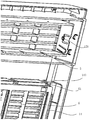
- FIG. 1 is a schematic block diagram of an embodiment of a window air conditioner of the present invention
- FIG. 2 is a partial exploded view of an embodiment of a window air conditioner of the present invention
- FIG. 3 is a partial structural schematic view 1 of an embodiment of a window air conditioner according to the present invention.
- FIG. 4 is a schematic structural view of an integrated bracket in an embodiment of a window type air conditioner according to the present invention.
- Figure 5 is a front elevational view showing an embodiment of a window type air conditioner of the present invention.
- FIG. 6 is a partial assembly view of an air outlet frame and an air inlet grille in an embodiment of a window air conditioner according to the present invention
- FIG. 7 is a partial structural schematic view of an air outlet in an embodiment of a window air conditioner according to the present invention.
- FIG. 8 is a partial structural schematic view of an air outlet frame in an embodiment of a window air conditioner according to the present invention.
- FIG. 9 is a partial schematic structural view of an air intake grille in an embodiment of a window air conditioner according to the present invention.
- a window type air conditioner 10 provided by the present invention comprises an outer casing and an indoor heat exchanger 22, an outdoor heat exchanger 23 and a motor 2 disposed in the outer casing.
- the rotating shafts at both ends of the motor are correspondingly provided with an indoor fan 20 and an outdoor fan 21.
- the outer casing is divided into an indoor side 10A and an outdoor side 10B.
- the indoor side is provided with an indoor heat exchanger 22, the indoor heat exchanger 22 is provided with an indoor fan, and corresponding air inlets and air outlets provided on the front surface of the outer casing, and the air inlet is provided with a detachable air inlet grille, and the air outlet is provided There is a detachable air outlet frame; the outdoor side is provided with a compressor, an outdoor heat exchanger 23, a motor 2, and an outdoor fan 21.
- the window air conditioner provided by the invention is improved for different parts, as follows:
- the bottom plate 11 of the outer casing 1 is provided with a heat insulating partition 4, and the heat insulating partition 4 divides the outer casing into an indoor side and an outdoor side, and the heat insulating partition 4 includes a front partition 41.
- the heat insulating volute 42 is fixed on the bottom plate 11 of the outer casing, the heat insulating volute 42 is disposed on the front partition 41, the indoor heat exchanger 22 is disposed on the heat insulating volute 42, and the indoor fan 20 is located in the heat insulating volute 42.
- the window type air conditioner further includes an integral bracket 3 configured to have a first mounting portion for mounting the fixed outdoor heat exchanger, and the integral bracket 3 is further configured to have a second mounting portion for mounting the fixed motor 2,
- the unitary bracket 3 is also configured to have a third mounting portion that connects the fixed front partition 41.
- the integrated bracket 3 is used to simultaneously mount the outdoor heat exchanger and the motor 2, and the motor 2 is directly fixed to the integral bracket 3 to ensure the position of the motor 2 is stable and reliable with respect to the integrated bracket 3, and at the same time, the integrated bracket 3 Also connected and fixed to the front partition 41, as a whole, after the rigid connection between the integrated bracket 3 and the front partition 41, the integral bracket 3 and the front partition 41 will be relatively unchanged, so that the integrated bracket is mounted on the integrated bracket.
- the position of the motor 2 on the 3 is stable and reliable with respect to the heat insulating volute 42 on the front partition 41.
- the posture of the motor 2 is not inclined by vibration or collision, and the position of the indoor fan relative to the heat insulating volute 42 is ensured, and at the same time, the outdoor fan is ensured relative to the tuyere of the integrated bracket 3.
- the position is kept stable, so that the interference between the indoor fan and the heat insulating volute 42 due to the change of the position of the motor 2 can be avoided, noise is generated, noise is reduced, and the reliability of use is improved.
- the heat insulating volute 42 is also connected with an air outlet 421, and the indoor air is sucked into the outer casing and exchanged with the indoor heat exchanger to enter the heat insulating volute 42 and output from the air outlet 421.
- the integrated bracket 3 includes an integrally formed rear partition 31, a motor bracket 32 and a connecting post 33.
- the motor bracket 32 is formed on the rear partition 31, and the connecting post 33 is formed on the motor bracket 32, and the rear partition 31 is In the first mounting portion, the motor bracket 32 is a second mounting portion, and the connecting post 33 is a third mounting portion.
- the integrated bracket 3 can be processed by injection molding, welding, etc., wherein the rear partition plate 31 serves as a first mounting portion for fixing the outdoor heat exchanger, and at the same time, the rear partition plate 31 is provided with a mounting hole 311.
- the outdoor fan 21 is located in the mounting hole 311.
- a plurality of air guiding plates 312 are disposed around the mounting hole 311.
- the plurality of air guiding plates 312 form a structure of the air guiding ring.
- the motor bracket 32 defines a mounting hole 321 for fixing the motor 2 to the motor.
- the connecting post 33 is fixedly coupled to the front partition 41 by screws, and a plurality of connecting posts 33 may be provided to be connected to the front partition 41 as needed.
- a support base 34 is formed between the rear partition plate 31 and the lower portion of the motor bracket 32.
- the support base 34 is fixed on the bottom plate 11 of the outer casing.
- the integrated bracket 3 is fixedly mounted on the bottom plate 11 through the support base 34.
- the support base 34 can be firmly and reliably connected to the bottom plate 11, and the support base 34 can further support the fixed rear partition 31 and the motor bracket 32.
- a cantilever 35 is formed between the rear partition plate 31 and the upper portion of the motor bracket 32.
- the cantilever 35 and the support base 34 can improve the connection reliability of the rear partition plate 31 and the motor bracket 32, and at the same time To improve the installation stability of the motor 2.
- the bottom of the indoor heat exchanger for the indoor side is further provided with a water receiving tray 12 on the bottom plate 11 of the outer casing.
- a water receiving tray 12 on the bottom plate 11 of the outer casing.
- the volute 42 affects the cooling effect.
- the water tray 12 is provided with a plurality of rows of support rib assemblies. Each row of support rib assemblies includes a plurality of support ribs 121, and the lower portion of the indoor heat exchanger abuts against the support ribs 121.
- the supporting rib 121 can carry the indoor heat exchanger on the one hand in the water receiving tray 12, and on the other hand, the supporting rib 121 can block the wind entering the indoor to reduce the air in the indoor side without passing through the indoor heat exchange.
- the device processes directly into the insulating volute 42.
- the support ribs 121 of one row of support rib assemblies and the corresponding support ribs 121 of the other row of support rib assemblies are formed with overlapping regions along the air inlet direction
- the supporting rib 121 is disposed in a gap formed between the indoor heat exchanger and the water receiving tray 12, and an overlapping area is formed between the corresponding supporting ribs 121 of the adjacent two rows, so that the air inlet resistance can be effectively increased.
- the support rib 121 may be an arc structure, a V-shaped structure or a U-shaped structure.
- the two sides of the air outlet 13 of the outer casing 1 are respectively provided with a connecting shaft 131 , and the two side walls of the air outlet frame 5 are respectively provided with shaft holes 51 ,
- the free end of the connecting shaft is provided with a guiding inclined surface 132, and the connecting shaft 131 is guided and fitted in the shaft hole 51 via the guiding inclined surface 132.
- the two side walls of the air outlet frame 5 can be guided via the guiding slope 132, and finally The assembly of the connecting shaft 131 into the shaft hole 51 realizes the assembly of the air outlet frame 5. Since the guiding inclined surface 132 is disposed on the connecting shaft 131, it is more convenient for the operator to move the air outlet frame 5 along the guiding inclined surface 132, and finally the connection is made.
- the shaft 131 is inserted into the shaft hole 51.
- the side wall of the air outlet frame 5 is further provided with an elastic plate 52, which is elastic.
- the plate 52 is located inside the shaft hole 51. Specifically, in the process of entering the shaft hole 51, the connecting shaft 131 will first abut against the elastic plate 52, and the elastic plate 52 is pressed by the connecting shaft 131 to be bent. After the connecting shaft 131 is engaged in the shaft hole 51, the elastic plate 52 is reset to release the blocking connecting shaft 131 from the shaft hole 51, and the elastic plate 52 is formed with the sliding rail 521, and the height of the sliding rail 521 is along The direction of the air outlet is gradually increased.
- the side wall of the air outlet frame 5 is further provided with a positioning rib 53.
- the positioning rib 53 is located inside the shaft hole 51, and the positioning rib 53 is an arc structure.
- the positioning rib 53 is half wrapped around the outside of the shaft hole 51, and passes through the protrusion.
- the positioning ribs 53 can limit the connecting shaft 131 during the process of installing the wind frame 5 by the operator, thereby improving assembly efficiency.
- a slot (not shown) is disposed at the bottom of the air inlet port 14, and the upper portion of the air inlet port 14 is provided with a first elastic claw 141 for entering the air.
- the bottom of the grid 6 is provided with a tongue (not shown), and the upper portion of the inlet grill 6 is provided with a second elastic claw 61, and the tongue is inserted into the slot, and the first elastic claw 141 and the second elastic claw 61 are inserted. Cards are packed together.
- the assembly of the air inlet grille 6 to the air inlet port 14 by means of two elastic claws being mutually engaged enables the operator to more easily fit the air inlet grille 6 into position, and at the same time, conventional techniques can be avoided.
- the claws When the claws are engaged with the slots, the claws on the air intake grille 6 easily interfere with the edges of the air inlets 14. After the air inlet grille 6 and the air inlet 14 are matched by the elastic claws, the hand feels light and is still not easy to fall off, the hand feeling has high tolerance to the tolerance of the components, the touch is uniform and the assembly reliability is stable.
- the top of the air inlet grille 6 is provided with a recess 62, and the second elastic claw 61 is located in the recess 62.
- the second elastic claw 61 is disposed in the recess 62 in a sunken manner, so that the first The two elastic claws 61 are lower than the top surface of the air inlet grille 6, so that the gap formed between the air inlet grille 6 and the air inlet grille 14 can be better narrowed, and the appearance effect is optimized to improve user experience.
- the first elastic claw 141 extends toward the inside of the outer casing, and the second elastic claw 61 extends toward the back of the air inlet grille 6.
- the front surface of the first elastic claw 141 is a first guiding surface
- the first elastic claw 141 is The back surface is a first positioning surface
- the front surface of the second elastic claw 61 is a second positioning surface
- the back surface of the second elastic claw 61 is a second guiding surface
- the slope of the first guiding surface and the second to lower surface is smaller than the first
- the slope of the positioning surface and the second positioning surface in particular, the difficulty of loading and unloading can be separately controlled by adjusting the slope of the positioning surface and the guiding surface, making the loading easier and the disassembly difficult.
Landscapes
- Engineering & Computer Science (AREA)
- Chemical & Material Sciences (AREA)
- Combustion & Propulsion (AREA)
- Mechanical Engineering (AREA)
- General Engineering & Computer Science (AREA)
- Physics & Mathematics (AREA)
- Thermal Sciences (AREA)
- Air-Conditioning Room Units, And Self-Contained Units In General (AREA)
- Structures Of Non-Positive Displacement Pumps (AREA)
- Air Filters, Heat-Exchange Apparatuses, And Housings Of Air-Conditioning Units (AREA)
Abstract
L'invention concerne un climatiseur de type sur fenêtre, lequel climatiseur comprend un boîtier, et un échangeur de chaleur intérieur, un échangeur de chaleur extérieur et un moteur électrique disposés à l'intérieur du boîtier, des axes rotatifs aux deux extrémités du moteur électrique comportant de manière correspondante un ventilateur intérieur et un ventilateur extérieur, une séparation d'isolation thermique étant disposée sur une plaque de base du boîtier, le boîtier étant divisé en un côté intérieur et un côté extérieur par la séparation d'isolation thermique, la séparation d'isolation thermique comprenant une plaque de séparation avant et une volute d'isolation thermique, la plaque de séparation avant étant fixée sur la plaque de base du boîtier, la volute d'isolation thermique étant disposée sur la plaque de séparation avant, l'échangeur de chaleur intérieur étant disposé sur la volute d'isolation thermique, et le ventilateur intérieur étant disposé dans la volute d'isolation thermique ; et lequel climatiseur du type sur fenêtre comprend en outre un support intégré, le support intégré étant configuré de façon à comporter une première partie de montage pour monter de manière fixe l'échangeur de chaleur extérieur sur celui-ci, le support intégré étant en outre configuré de façon à comporter une deuxième partie de montage pour monter de manière fixe le moteur électrique sur celui-ci, et le support intégré étant en outre configuré de façon à comporter une troisième partie de montage reliée de manière fixe à la plaque de séparation avant.
Priority Applications (1)
| Application Number | Priority Date | Filing Date | Title |
|---|---|---|---|
| US16/650,724 US11578879B2 (en) | 2017-09-30 | 2018-09-18 | Window-type air conditioner |
Applications Claiming Priority (2)
| Application Number | Priority Date | Filing Date | Title |
|---|---|---|---|
| CN201710917589.5A CN109611954A (zh) | 2017-09-30 | 2017-09-30 | 窗式空调 |
| CN201710917589.5 | 2017-09-30 |
Publications (1)
| Publication Number | Publication Date |
|---|---|
| WO2019062607A1 true WO2019062607A1 (fr) | 2019-04-04 |
Family
ID=65903738
Family Applications (1)
| Application Number | Title | Priority Date | Filing Date |
|---|---|---|---|
| PCT/CN2018/106311 Ceased WO2019062607A1 (fr) | 2017-09-30 | 2018-09-18 | Climatiseur du type sur fenêtre |
Country Status (3)
| Country | Link |
|---|---|
| US (1) | US11578879B2 (fr) |
| CN (1) | CN109611954A (fr) |
| WO (1) | WO2019062607A1 (fr) |
Cited By (3)
| Publication number | Priority date | Publication date | Assignee | Title |
|---|---|---|---|---|
| CN111256214A (zh) * | 2020-03-09 | 2020-06-09 | 江门市宝士制冷电器有限公司 | 一种窗式空调器 |
| CN114508842A (zh) * | 2020-11-17 | 2022-05-17 | 宁波奥克斯电气股份有限公司 | 一种风道组件以及空调器 |
| EP4043806A4 (fr) * | 2019-11-11 | 2022-12-07 | GD Midea Air-Conditioning Equipment Co., Ltd. | Climatiseur mobile |
Families Citing this family (2)
| Publication number | Priority date | Publication date | Assignee | Title |
|---|---|---|---|---|
| CN212511740U (zh) * | 2020-04-30 | 2021-02-09 | 广东美的制冷设备有限公司 | 空调器外壳组件与空调器 |
| CN111854135A (zh) * | 2020-08-24 | 2020-10-30 | 广东海悟科技有限公司 | 一种机柜空调的中框结构 |
Citations (8)
| Publication number | Priority date | Publication date | Assignee | Title |
|---|---|---|---|---|
| CN1727768A (zh) * | 2004-07-30 | 2006-02-01 | Lg电子株式会社 | 空调机 |
| CN106016487A (zh) * | 2016-06-30 | 2016-10-12 | 珠海格力电器股份有限公司 | 导流圈组件及空调穿墙机 |
| CN106885358A (zh) * | 2015-12-15 | 2017-06-23 | 珠海格力电器股份有限公司 | 接水盘及空调器 |
| CN106895497A (zh) * | 2017-02-21 | 2017-06-27 | 广东志高空调有限公司 | 一种静音顶出风窗式空调 |
| US9696044B2 (en) * | 2015-07-15 | 2017-07-04 | Haier US Applicance Solutions, Inc. | Air conditioner units and methods for providing make-up air |
| CN207422454U (zh) * | 2017-09-30 | 2018-05-29 | 青岛海尔空调器有限总公司 | 具有防漏风功能的窗式空调 |
| CN207584932U (zh) * | 2017-09-30 | 2018-07-06 | 青岛海尔空调器有限总公司 | 一体式空调 |
| CN207936330U (zh) * | 2017-09-30 | 2018-10-02 | 青岛海尔空调器有限总公司 | 窗机空调 |
Family Cites Families (9)
| Publication number | Priority date | Publication date | Assignee | Title |
|---|---|---|---|---|
| JPS62119333A (ja) * | 1985-11-19 | 1987-05-30 | Matsushita Seiko Co Ltd | 冷風扇風機 |
| KR100441000B1 (ko) * | 2001-11-08 | 2004-07-21 | 삼성전자주식회사 | 팬케이싱을 갖춘 일체형 공기조화기 |
| CN1542329A (zh) * | 2003-04-30 | 2004-11-03 | 乐金电子(天津)电器有限公司 | 窗式空调机的室外侧空气流动结构 |
| CN203396042U (zh) * | 2013-06-20 | 2014-01-15 | 海尔集团公司 | 一种窗式空调器及其电机固定机构 |
| JP6369684B2 (ja) * | 2014-10-10 | 2018-08-08 | 株式会社富士通ゼネラル | 天井埋込型空気調和機 |
| CN204757175U (zh) | 2015-07-06 | 2015-11-11 | 珠海格力电器股份有限公司 | 一种窗机空调 |
| CN205641445U (zh) * | 2016-03-28 | 2016-10-12 | 青岛海尔空调器有限总公司 | 一种窗式空调器的电机固定结构 |
| CN106247473A (zh) * | 2016-09-22 | 2016-12-21 | 珠海格力电器股份有限公司 | 窗式空调器 |
| CN106246581B (zh) * | 2016-09-22 | 2018-08-07 | 珠海格力电器股份有限公司 | 一种加压风机结构及具有该结构的空调 |
-
2017
- 2017-09-30 CN CN201710917589.5A patent/CN109611954A/zh active Pending
-
2018
- 2018-09-18 WO PCT/CN2018/106311 patent/WO2019062607A1/fr not_active Ceased
- 2018-09-18 US US16/650,724 patent/US11578879B2/en active Active
Patent Citations (8)
| Publication number | Priority date | Publication date | Assignee | Title |
|---|---|---|---|---|
| CN1727768A (zh) * | 2004-07-30 | 2006-02-01 | Lg电子株式会社 | 空调机 |
| US9696044B2 (en) * | 2015-07-15 | 2017-07-04 | Haier US Applicance Solutions, Inc. | Air conditioner units and methods for providing make-up air |
| CN106885358A (zh) * | 2015-12-15 | 2017-06-23 | 珠海格力电器股份有限公司 | 接水盘及空调器 |
| CN106016487A (zh) * | 2016-06-30 | 2016-10-12 | 珠海格力电器股份有限公司 | 导流圈组件及空调穿墙机 |
| CN106895497A (zh) * | 2017-02-21 | 2017-06-27 | 广东志高空调有限公司 | 一种静音顶出风窗式空调 |
| CN207422454U (zh) * | 2017-09-30 | 2018-05-29 | 青岛海尔空调器有限总公司 | 具有防漏风功能的窗式空调 |
| CN207584932U (zh) * | 2017-09-30 | 2018-07-06 | 青岛海尔空调器有限总公司 | 一体式空调 |
| CN207936330U (zh) * | 2017-09-30 | 2018-10-02 | 青岛海尔空调器有限总公司 | 窗机空调 |
Cited By (3)
| Publication number | Priority date | Publication date | Assignee | Title |
|---|---|---|---|---|
| EP4043806A4 (fr) * | 2019-11-11 | 2022-12-07 | GD Midea Air-Conditioning Equipment Co., Ltd. | Climatiseur mobile |
| CN111256214A (zh) * | 2020-03-09 | 2020-06-09 | 江门市宝士制冷电器有限公司 | 一种窗式空调器 |
| CN114508842A (zh) * | 2020-11-17 | 2022-05-17 | 宁波奥克斯电气股份有限公司 | 一种风道组件以及空调器 |
Also Published As
| Publication number | Publication date |
|---|---|
| US20200278122A1 (en) | 2020-09-03 |
| US11578879B2 (en) | 2023-02-14 |
| CN109611954A (zh) | 2019-04-12 |
Similar Documents
| Publication | Publication Date | Title |
|---|---|---|
| WO2019062607A1 (fr) | Climatiseur du type sur fenêtre | |
| CN105318438B (zh) | 空调室内机 | |
| CN106765654B (zh) | 空调装置 | |
| US11480346B2 (en) | Air conditioner | |
| WO2016154953A1 (fr) | Unité intérieure de climatiseur | |
| US10365007B2 (en) | Ceiling-embedded air conditioner | |
| EP3081876B1 (fr) | Conditionneur d'air intégré au plafond | |
| CN105333509B (zh) | 空调室内机 | |
| KR101852800B1 (ko) | 공기 조화기의 실내기 | |
| KR20180066546A (ko) | 공기조화기 | |
| JP7034341B2 (ja) | 空気調和機の室外機 | |
| CN207584932U (zh) | 一体式空调 | |
| US12092358B2 (en) | Fresh air assembly, air conditioner indoor unit, and air conditioner | |
| CN103429966B (zh) | 空调机 | |
| US20130025822A1 (en) | Ventilation apparatus | |
| CN207936330U (zh) | 窗机空调 | |
| CN207422454U (zh) | 具有防漏风功能的窗式空调 | |
| CN218495094U (zh) | 空调室内机 | |
| CN218495093U (zh) | 外壳组件及空调室内机 | |
| CN218119901U (zh) | 接水盘及空调室内机 | |
| CN203478453U (zh) | 室外机 | |
| CN100436952C (zh) | 空调机的室内机 | |
| CN221648714U (zh) | 空气处理设备 | |
| CN205878361U (zh) | 一种空调器室内机 | |
| WO2025035725A1 (fr) | Unité de climatisation intérieure |
Legal Events
| Date | Code | Title | Description |
|---|---|---|---|
| 121 | Ep: the epo has been informed by wipo that ep was designated in this application |
Ref document number: 18861137 Country of ref document: EP Kind code of ref document: A1 |
|
| NENP | Non-entry into the national phase |
Ref country code: DE |
|
| 122 | Ep: pct application non-entry in european phase |
Ref document number: 18861137 Country of ref document: EP Kind code of ref document: A1 |