WO2019065501A1 - Batterie secondaire rectangulaire, module de batterie, dispositif de stockage d'énergie, véhicule et objet volant - Google Patents
Batterie secondaire rectangulaire, module de batterie, dispositif de stockage d'énergie, véhicule et objet volant Download PDFInfo
- Publication number
- WO2019065501A1 WO2019065501A1 PCT/JP2018/035067 JP2018035067W WO2019065501A1 WO 2019065501 A1 WO2019065501 A1 WO 2019065501A1 JP 2018035067 W JP2018035067 W JP 2018035067W WO 2019065501 A1 WO2019065501 A1 WO 2019065501A1
- Authority
- WO
- WIPO (PCT)
- Prior art keywords
- electrode terminal
- lid
- secondary battery
- convex portion
- corners
- Prior art date
- Legal status (The legal status is an assumption and is not a legal conclusion. Google has not performed a legal analysis and makes no representation as to the accuracy of the status listed.)
- Ceased
Links
Images






Classifications
-
- H—ELECTRICITY
- H01—ELECTRIC ELEMENTS
- H01M—PROCESSES OR MEANS, e.g. BATTERIES, FOR THE DIRECT CONVERSION OF CHEMICAL ENERGY INTO ELECTRICAL ENERGY
- H01M50/00—Constructional details or processes of manufacture of the non-active parts of electrochemical cells other than fuel cells, e.g. hybrid cells
- H01M50/10—Primary casings; Jackets or wrappings
- H01M50/102—Primary casings; Jackets or wrappings characterised by their shape or physical structure
- H01M50/103—Primary casings; Jackets or wrappings characterised by their shape or physical structure prismatic or rectangular
-
- H—ELECTRICITY
- H01—ELECTRIC ELEMENTS
- H01M—PROCESSES OR MEANS, e.g. BATTERIES, FOR THE DIRECT CONVERSION OF CHEMICAL ENERGY INTO ELECTRICAL ENERGY
- H01M50/00—Constructional details or processes of manufacture of the non-active parts of electrochemical cells other than fuel cells, e.g. hybrid cells
- H01M50/20—Mountings; Secondary casings or frames; Racks, modules or packs; Suspension devices; Shock absorbers; Transport or carrying devices; Holders
- H01M50/204—Racks, modules or packs for multiple batteries or multiple cells
- H01M50/207—Racks, modules or packs for multiple batteries or multiple cells characterised by their shape
- H01M50/209—Racks, modules or packs for multiple batteries or multiple cells characterised by their shape adapted for prismatic or rectangular cells
-
- H—ELECTRICITY
- H01—ELECTRIC ELEMENTS
- H01M—PROCESSES OR MEANS, e.g. BATTERIES, FOR THE DIRECT CONVERSION OF CHEMICAL ENERGY INTO ELECTRICAL ENERGY
- H01M50/00—Constructional details or processes of manufacture of the non-active parts of electrochemical cells other than fuel cells, e.g. hybrid cells
- H01M50/10—Primary casings; Jackets or wrappings
- H01M50/147—Lids or covers
- H01M50/148—Lids or covers characterised by their shape
- H01M50/15—Lids or covers characterised by their shape for prismatic or rectangular cells
-
- H—ELECTRICITY
- H01—ELECTRIC ELEMENTS
- H01M—PROCESSES OR MEANS, e.g. BATTERIES, FOR THE DIRECT CONVERSION OF CHEMICAL ENERGY INTO ELECTRICAL ENERGY
- H01M50/00—Constructional details or processes of manufacture of the non-active parts of electrochemical cells other than fuel cells, e.g. hybrid cells
- H01M50/50—Current conducting connections for cells or batteries
- H01M50/543—Terminals
- H01M50/547—Terminals characterised by the disposition of the terminals on the cells
- H01M50/55—Terminals characterised by the disposition of the terminals on the cells on the same side of the cell
-
- H—ELECTRICITY
- H01—ELECTRIC ELEMENTS
- H01M—PROCESSES OR MEANS, e.g. BATTERIES, FOR THE DIRECT CONVERSION OF CHEMICAL ENERGY INTO ELECTRICAL ENERGY
- H01M50/00—Constructional details or processes of manufacture of the non-active parts of electrochemical cells other than fuel cells, e.g. hybrid cells
- H01M50/50—Current conducting connections for cells or batteries
- H01M50/543—Terminals
- H01M50/552—Terminals characterised by their shape
- H01M50/553—Terminals adapted for prismatic, pouch or rectangular cells
-
- H—ELECTRICITY
- H01—ELECTRIC ELEMENTS
- H01M—PROCESSES OR MEANS, e.g. BATTERIES, FOR THE DIRECT CONVERSION OF CHEMICAL ENERGY INTO ELECTRICAL ENERGY
- H01M2220/00—Batteries for particular applications
- H01M2220/20—Batteries in motive systems, e.g. vehicle, ship, plane
-
- H—ELECTRICITY
- H01—ELECTRIC ELEMENTS
- H01M—PROCESSES OR MEANS, e.g. BATTERIES, FOR THE DIRECT CONVERSION OF CHEMICAL ENERGY INTO ELECTRICAL ENERGY
- H01M50/00—Constructional details or processes of manufacture of the non-active parts of electrochemical cells other than fuel cells, e.g. hybrid cells
- H01M50/20—Mountings; Secondary casings or frames; Racks, modules or packs; Suspension devices; Shock absorbers; Transport or carrying devices; Holders
- H01M50/271—Lids or covers for the racks or secondary casings
-
- H—ELECTRICITY
- H01—ELECTRIC ELEMENTS
- H01M—PROCESSES OR MEANS, e.g. BATTERIES, FOR THE DIRECT CONVERSION OF CHEMICAL ENERGY INTO ELECTRICAL ENERGY
- H01M50/00—Constructional details or processes of manufacture of the non-active parts of electrochemical cells other than fuel cells, e.g. hybrid cells
- H01M50/20—Mountings; Secondary casings or frames; Racks, modules or packs; Suspension devices; Shock absorbers; Transport or carrying devices; Holders
- H01M50/296—Mountings; Secondary casings or frames; Racks, modules or packs; Suspension devices; Shock absorbers; Transport or carrying devices; Holders characterised by terminals of battery packs
-
- Y—GENERAL TAGGING OF NEW TECHNOLOGICAL DEVELOPMENTS; GENERAL TAGGING OF CROSS-SECTIONAL TECHNOLOGIES SPANNING OVER SEVERAL SECTIONS OF THE IPC; TECHNICAL SUBJECTS COVERED BY FORMER USPC CROSS-REFERENCE ART COLLECTIONS [XRACs] AND DIGESTS
- Y02—TECHNOLOGIES OR APPLICATIONS FOR MITIGATION OR ADAPTATION AGAINST CLIMATE CHANGE
- Y02E—REDUCTION OF GREENHOUSE GAS [GHG] EMISSIONS, RELATED TO ENERGY GENERATION, TRANSMISSION OR DISTRIBUTION
- Y02E60/00—Enabling technologies; Technologies with a potential or indirect contribution to GHG emissions mitigation
- Y02E60/10—Energy storage using batteries
-
- Y—GENERAL TAGGING OF NEW TECHNOLOGICAL DEVELOPMENTS; GENERAL TAGGING OF CROSS-SECTIONAL TECHNOLOGIES SPANNING OVER SEVERAL SECTIONS OF THE IPC; TECHNICAL SUBJECTS COVERED BY FORMER USPC CROSS-REFERENCE ART COLLECTIONS [XRACs] AND DIGESTS
- Y02—TECHNOLOGIES OR APPLICATIONS FOR MITIGATION OR ADAPTATION AGAINST CLIMATE CHANGE
- Y02P—CLIMATE CHANGE MITIGATION TECHNOLOGIES IN THE PRODUCTION OR PROCESSING OF GOODS
- Y02P70/00—Climate change mitigation technologies in the production process for final industrial or consumer products
- Y02P70/50—Manufacturing or production processes characterised by the final manufactured product
Definitions
- Embodiments relate to a square secondary battery, a battery module, a power storage device, a vehicle, and a projectile.
- a lithium ion secondary battery is raised as a secondary battery with a high energy density which responds to it.
- secondary batteries such as lead storage batteries and nickel hydrogen batteries are used as large-sized, large-capacity power sources represented by electric vehicles, hybrid vehicles, electric motorcycles, forklifts, etc.
- lithium ion with high energy density has been used Development for adoption of secondary batteries has become active. The development of lithium ion secondary batteries that respond to that has been made larger and larger while considering the long life and safety.
- a battery pack containing a large number of batteries connected in series or in parallel is used because the drive power is large, and a metal can that is lighter and thinner is used from the viewpoint of mounting density
- studies of rectangular batteries having a rectangular parallelepiped shape have been actively conducted.
- the embodiment provides a square secondary battery and a battery module using the square secondary battery, which is easy to evaluate the outer shape, a power storage device, a vehicle, and a vehicle.
- the prismatic secondary battery of the embodiment has an outer can having a bottom with a substantially rectangular cross section and having an opening, a power generation element housed in the outer can, a positive electrode terminal and a negative electrode terminal, A lid covering the opening of the can, and at least one of the side surface of the outer surface of the outer can, the bottom surface of the outer surface of the outer can and the positive and negative terminals of the outer surface of the lid There are two or more convex portions.
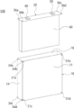
- FIG. 1 is a perspective view of a secondary battery of the embodiment.
- FIG. 2 is an exploded perspective view of the secondary battery of the embodiment.
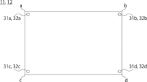
- Drawing 3 is a key map of the side of the armored can of an embodiment.
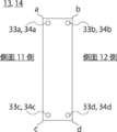
- Drawing 4 is a key map of the side of the armored can of an embodiment.
- Drawing 5 is a key map of the bottom of the armored can of an embodiment.
- Drawing 6 is a key map of the bottom of the armored can of an embodiment.
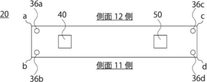
- FIG. 7 is a conceptual view of the lid of the embodiment.
- FIG. 8 is a conceptual view of the lid of the embodiment.
- FIG. 9 is a perspective development view of the battery module of the embodiment.
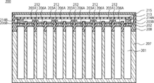
- FIG. 10 is a cross-sectional view of the battery module of the embodiment.
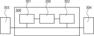
- FIG. 11 is a conceptual diagram of the power storage device of the embodiment.
- FIG. 12 is a conceptual view of a vehicle of the embodiment.
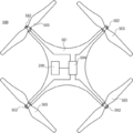
- FIG. 13 is a conceptual view of the projectile of the embodiment.
- the first embodiment relates to a rectangular secondary battery.
- the secondary battery of the first embodiment is shown in the perspective view of FIG.
- the secondary battery 100 shown in FIG. 1 includes an outer can 10, a power generation element accommodated in the outer can 10, and a lid 20, and the outer can 10 and the lid 20 have convex portions (31, 34, 36) Exists.
- the lid 20 has a positive electrode terminal 40 and a negative electrode terminal 50.
- the outer can 10 has four side surfaces 11, 12, 13 and 14 and a bottom surface 15. In the angle of the perspective view of FIG. 1, the side surface 12, the side surface 13, and the bottom surface 15 are at positions where they are blind.
- the distance between the convex portions present in different planes the distance between two or more convex portions present in one plane, the distance between one convex portion and the positive electrode terminal 40, one convex portion as the negative electrode terminal 50
- the external shape of the secondary battery 100 can be evaluated from the distance between
- the convex portion also on the lid 20
- the accuracy of the external shape evaluation can be enhanced, and the error evaluation of the battery shape can be easily performed.
- the secondary battery 100 whose external shape has been evaluated is easy to evaluate its shape error when being incorporated into a module or the like, it is also useful in module design.
- it is a perspective view from the direction where the side surface 11, the side surface 14, the bottom face 15, and the outer surface of the lid 20 of the outer surface of the armored can 10 of FIG. 1 can be confirmed, A convex part exists in each surface. The presence of two or more convex portions on one surface makes it possible to measure the shape of the secondary battery from the distance between the convex portions of the surface.
- the armored can 10 of embodiment has an opening part by the bottomed cylindrical form whose cross-sectional shape is a substantially square.
- the thickness of the outer can 10 is typically 0.2 ⁇ m or more and 1.5 mm or less.
- the outer can 10 and the lid 10 are preferably made of metal using aluminum, aluminum alloy, iron, stainless steel or the like.
- the cross-sectional shape of the outer can 10 is substantially square.
- the height of the opening outer case 10 of the outer can is typically 30 mm or more and 180 mm or less.
- variety of the armored can 10 is 60 mm or more and 180 mm or less typically.
- the depth of the outer can 10 is typically 4 mm or more and 45 mm or less.
- the cross-sectional shapes of the side surfaces 11, 12, 13, 14 and the bottom surface 15 of the outer can 10 may be semi-elliptical. By providing the convex portion even in the semi-elliptical shape, the outer shape evaluation of the square secondary battery 100 becomes easy.
- FIG. 2 shows an exploded perspective view of the secondary battery 100 of the first embodiment.
- the power generation element 60 connected to the positive electrode terminal 40 and the negative electrode terminal 50 of the lid 20 is shown.
- the positive electrode terminal 40 and the negative electrode terminal 50 of the lid 20 are electrically insulated from the lid 20.
- the power generation element 60 has a positive electrode, a separator and a negative electrode.
- the positive electrode of the power generation element 60 is electrically connected to the positive electrode terminal 40.
- the negative electrode of the power generation element 60 is electrically connected to the negative electrode terminal 50.
- An electrolyte (not shown) is accommodated in the outer can 10 together with the power generation element 60.
- the power generation element 60 includes, for example, a wound electrode group.
- the electrolyte is a non-aqueous electrolyte or a water-based electrolyte.
- the lid 20 may further have a gas valve, an electrolytic solution inlet, and the like (not shown).
- the opening 16 is shown.
- the opening 16 is covered by the lid 20 and joined to the lid 20.
- the outer can 10 is airtightly sealed by the lid 20 at the opening 16 of the outer can 10.
- the outer can 10 and the lid 20 are preferably joined by, for example, laser welding.
- the shape of the lid 20 depends on the shape of the opening 16, but is typically approximately square.
- the thickness of the lid 20 is typically 0.2 ⁇ m or more and 2.0 ⁇ m or less.
- the convex part of the side surface 11 of the armored can 10 is demonstrated.
- a convex portion 31 exists on the side surface 11.
- the side surface 12 has a convex portion 32.
- four corners a, b, c, d of the side surfaces 11, 12 are shown.
- the outer shape can be evaluated. Besides, the thickness of the outer can 10 can also be evaluated from the distance between the one or more protrusions 31 and the one or more protrusions 32. In addition, the distance between the one or more protrusions 31 and 32 and the positive electrode terminal 40 and the distance between the one or more protrusions 31 and 32 and the negative electrode terminal 50 can also be evaluated. If there are three convex portions 31 and 32, three distances between the convex portions 31 and 32 can be obtained. Therefore, the outer shape evaluation of the side surfaces 11 and 12 can be performed in more detail than the distance from two convex portions. It is preferable at the point which can be done.
- the outer shape evaluation of the side surfaces 11 and 12 can be performed in more detail than the distances from the three convex portions.
- the long side of the bottom surface 15 of the outer can 10 is included as the side of the side surfaces 11 and 12.
- the convex portions 31 and 32 are preferably present in the vicinity of at least one of the four corners a, b, c, and d. Specifically, the convex portions 31 and 32 are preferably 10 mm or less (the distance between the corner and the convex portion) from the corner.
- the protrusions 31 and 32 are more preferably 0.5 mm or more and 5 mm or less from the corners, and still more preferably 0.5 mm or more and 3 mm or less.
- the distances between the corners a, b, c, d and the protrusions 31, 32 are the distances from the corners to the vertices of the nearest protrusions 31, 32 in the vicinity thereof.
- the convex portions 31 and 32 are also present at the central portions of the side surfaces 11 and 12, it is preferable because detection of expansion at the central portions of the side surfaces 11 and 12 is further facilitated.
- the convex portions 31 and 32 be present in the vicinity of all the four corners a, b, c and d. Therefore, as shown in the conceptual view of FIG. 3, it is preferable that one convex portion 31, 32 be present at four corners a, b, c, d at 10 mm or less from the four corners a, b, c, d. . Further, it is preferable that one convex portion 31 or 32 is present at each of the corners a, b, c, d at four to ten mm from the four corners a, b, c, d.
- one convex portion 31 and 32 be present at each of the corners a, b, c and d at 0.5 mm or more and 3 mm or less from the four corners a, b, c, d.
- the difference between the maximum value and the minimum value of the distances between the convex portions 31 and 32 and the corners is within 20% of the average value of the distances between the convex portions 31 and 32 and the corners, There is little variation in the position of.
- the corners a, b, c and d of the side surfaces 11 and 12 are determined by the following method. Find the approximate straight lines of the four sides of the side faces 11 and 12, then define the four vertices of a square formed from the four approximate straight lines. Then, the diagonals of the diagonals of the four apexes are drawn, and the intersections of the diagonals and the contours of the side surfaces 11 and 12 are defined as corners a, b, c, and d.
- the convex part of the side surfaces 13 and 14 of the armored can 10 is demonstrated.
- the side view 13 and 14 of the outer surface of the armored can 10 in which the hemispherical or conical convex part 33 and 34 exists in the conceptual diagram of FIG. 4 is shown.
- the convex portion 33 is present on the side surface 13.
- the convex portion 34 is present on the side surface 14.
- four corners a, b, c, d of the side surfaces 13, 14 are shown.
- the outer shape can be evaluated. Besides, the width of the outer can 10 can also be evaluated from the distance between the one or more projections 33 and the one or more projections 34. The distance between one or more projections 33 and 34 and positive electrode terminal 40 and the distance between one or more projections 33 and 34 and negative electrode terminal 50 can also be evaluated. If there are three convex portions 33 and 34, three distances between the convex portions 33 and 34 can be obtained. Therefore, the outer shape evaluation of the side surfaces 13 and 14 can be performed in more detail than the distance from two convex portions. It is preferable at the point which can be done.
- the outer shape evaluation of the side faces 13 and 14 can be performed in more detail than the distances from the three convex parts.
- the short side of the bottom surface 15 of the outer can 10 is included as the side of the side surfaces 13 and 14. Since the side surfaces 13 and 14 are side surfaces narrower in area than the side surfaces 11 and 12, the distance between the projections is narrow. Therefore, if convex portions are provided on one or two sides of the side surfaces, it is preferable to provide the convex portions on the side surfaces 11 and 12 rather than the side surfaces 13 and 14.
- the protrusions 33 and 34 are preferably present in the vicinity of at least one of the four corners a, b, c, and d. Specifically, the protrusions 33 and 34 are preferably 10 mm or less (the distance between the corner and the protrusion) from the corner. The protrusions 33 and 34 are more preferably 0.5 mm or more and 5 mm or less from the corners, and still more preferably 0.5 mm or more and 3 mm or less.
- the distance between the corners a, b, c, d and the projections 33, 34 is the distance from each corner to the apex of the nearest projections 33, 34 in the vicinity.
- the convex portions 33 and 34 are also present at the central portions of the side surfaces 13 and 14, it is preferable because detection of expansion at the central portions of the side surfaces 13 and 14 is further facilitated.
- the convex portions 33 and 34 be present in the vicinity of all the four corners a, b, c and d. Accordingly, as shown in the conceptual view of FIG. 4, it is preferable that one convex portion 33, 34 be present at four corners a, b, c, d at 10 mm or less from the four corners a, b, c, d. . Further, it is preferable that one convex portion 33, 34 is present at each of the corners a, b, c, d at four to ten mm from the four corners a, b, c, d.
- one convex portion 33, 34 be present at each of the corners a, b, c, d at 0.5 mm or more and 3 mm or less from the four corners a, b, c, d.
- the difference between the maximum value and the minimum value of the distances between the convex portions 33 and 34 and the corners is within 20% of the average value of the distances between the convex portions 33 and 34 and the corners. There is little variation in the position of.
- the corners a, b, c and d of the side surfaces 13 and 14 are determined by the following method.
- the approximate straight lines of the four sides of the side surfaces 13 and 14 are obtained, and then the four vertices of a square formed from the four approximate straight lines are determined.
- the diagonals of the diagonals of the four vertices are drawn, and the intersections of the diagonals and the contours of the side surfaces 13 and 14 are set as corners a, b, c, and d.
- four corners are fixed even if the side surfaces 13 and 14 are not rectangular, and the distances from the corners to the convex portions 33a, 33b, 33c and 33d (34a, 34b, 34c and 34d) can be determined.
- the bottom view 15 of the outer surface of the armored can 10 in which the hemispherical or conical convex part 35 exists in the conceptual diagram of FIG. 5 is shown.
- a convex portion 35 is present on the bottom surface 15.
- four corners a, b, c, d of the bottom surface 15 are shown.
- the distance between the projection 35 on the bottom and the positive electrode terminal 40 or the negative electrode terminal 50 of the lid 16 can be evaluated.
- any one or more of the distance from the positive electrode terminal 40 to the bottom surface 15, the distance from the negative electrode terminal 50 to the bottom surface 15, the height of the secondary battery 100, or the height of the outer can 10 is evaluated can do.
- the convex portions 35 a, 35 b, 35 c, 35 d are present in the vicinity of all four corners a, b, c, d, two convex portions 35 are present on the bottom surface 15. If it exists, the outer shape of the bottom surface 15 can also be evaluated from the distance between the two projections 35.
- the outer shape evaluation of the bottom surface 15 can be performed in more detail than only the distance from the two convex portions. Since four distances between convex portions are required when there are four convex portions 35, it is preferable in that the outer shape of the bottom surface 15 can be evaluated in detail rather than distances from three convex portions.
- the convex portion 35 is preferably present in the vicinity of at least one of the four corners a, b, c, and d of the bottom surface 15.
- the protrusion 35 is preferably 10 mm or less (the distance between the corner and the protrusion) from the corner of the bottom surface 15.
- the protrusion 35 is more preferably 0.5 mm or more and 5 mm or less from the corner of the bottom surface 15, and still more preferably 0.5 mm or more and 3 mm or less.
- the distances between the corners a, b, c, d and the projections 35 are the distances from the corners to the apexes of the nearest projections 35 in the vicinity thereof.
- the projections 35 be present in the vicinity of all four corners a, b, c, d. Accordingly, as shown in the conceptual view of FIG. 5, it is preferable that one convex portion 35 be present at four corners a, b, c, d at 10 mm or less and at each corner a, b, c, d. Further, it is preferable that one convex portion 35 is present at four corners a, b, c, d from 0.5 mm to 10 mm and one at each corner a, b, c, d.
- one convex portion 35 exists at four corners a, b, c, d from 0.5 mm to 3 mm and at each corner a, b, c, d.
- the difference between the maximum value and the minimum value of the distance between each protrusion 35 and the corner is within 20% of the average value of the distance between each protrusion 35 and the corner, the variation in the position of the protrusion 35 is small. Preferred.
- the form in which the linear convex parts 35e and 35f exist in the bottom face 15 of the outer surface of the armored can 10 is also preferable.
- the distance between the projection 35 on the bottom and the positive electrode terminal 40 or the negative electrode terminal 50 of the lid 16 can be evaluated.
- any one or more of the distance from the positive electrode terminal 40 to the bottom surface 15, the distance from the negative electrode terminal 50 to the bottom surface 15, the height of the secondary battery 100, or the height of the outer can 10 is evaluated can do. Since there are two linear protrusions 35e and 35f, the outer shape of the bottom 15 of the secondary battery 100 can also be evaluated from the distance between the linear protrusions 35e and 35f.
- the aspect ratio (length / width) of the linear protrusions 35e and 35f is preferably 3 or more and 10 or less.
- linear convex parts 35e and 35f it is preferable that the distance from the two short sides e and f of bottom 15 is 10 mm or less, respectively. It is more preferable that the distance from the two short sides e and f of the bottom surface 15 be 0.5 mm or more and 5 mm or less, and the linear convex portions 35 e and 35 f be 0.5 mm or more and 3 mm or less More preferable. .
- the corners a, b, c, d of the bottom surface 15 are determined by the following method. An approximate straight line of the four sides of the bottom surface 15 is determined, and then four vertices of a square formed from the four approximate straight lines are determined. Then, the diagonals of the diagonals of the four vertices are drawn, and the intersections of the diagonals and the contour of the bottom surface 15 are set as corners a, b, c, d. By this method, four corners are determined even if the bottom surface 15 is not rectangular, and the distances from the corners to the convex portions 35a, 35b, 35c, 35d are determined.
- the line segment connecting the corners obtained as described above can be regarded as the short side side.
- the short side e is regarded as a line connecting the corner a and the corner b
- the short side f is considered as a line connecting the corner c and the corner d.
- cover 20 in which the hemispherical or conical convex part 36 exists in the conceptual diagram of FIG. 7 is shown.
- a convex portion 36 exists on the surface of the outer surface of the lid 20 having the positive electrode terminal and the negative electrode terminal.
- four corners a, b, c, d of the lid 20 are shown.
- the distance between the convex portion 36 of the lid 16 and the positive electrode terminal 40 or the negative electrode terminal 50 of the lid 16 can be evaluated.
- the convex portions 36 a, 36 b, 36 c and 36 d are present in the vicinity of all four corners a, b, c and d, two convex portions 35 are provided on the lid 20. If it is, the outer shape of the lid 16 can also be evaluated from the distance between the two projections 36. If there are three convex portions 36, three distances between the convex portions 36 are obtained, which is preferable in that the outer shape evaluation of the lid 20 can be performed in more detail than by the distance from the two convex portions. Since four distances between the convex portions are required when there are four convex portions 36, it is preferable in that the outer shape evaluation of the lid 20 can be performed in more detail than the distances from the three convex portions.
- the convex portion 36 is preferably present in the vicinity of at least one of the four corners a, b, c, and d.
- the protrusion 36 is preferably 10 mm or less (the distance between the corner and the protrusion) from the corner.
- the convex portion 36 is more preferably 0.5 mm or more and 5 mm or less from the corner, and still more preferably 0.5 mm or more and 3 mm or less.
- the distance between the corners a, b, c, d and the convex portion 36 is the distance from each corner to the vertex of the closest convex portion 36 in the vicinity thereof.
- the convex portion 36 be present in the vicinity of all four corners a, b, c, d. Accordingly, as shown in the conceptual view of FIG. 7, one convex portion 36 may be present at 10 mm or less from the four corners a, b, c, d of the lid 20 and at each corner a, b, c, d preferable. Further, it is preferable that one convex portion 36 exists at four corners a, b, c, d of the lid 20 at 0.5 mm or more and 10 mm or less and one at each corner a, b, c, d.
- one convex portion 36 exists at four corners a, b, c, d of the lid 20 at 0.5 mm or more and 3 mm or less and at each corner a, b, c, d. Further, the difference between the maximum value and the minimum value of the distance between each convex portion 36 and the corner is within 20% of the average value of the distance between each convex portion 36 and the corner, the variation in the position of the convex portion 36 is small. Preferred.
- cover 20 of the outer surface of the armored can 10 is also preferable.
- the distance between the convex portions 36 e and f of the lid 16 and the positive electrode terminal 40 or the negative electrode terminal 50 of the lid 16 can be evaluated. Since there are two linear convex portions 36e and 36f, it is possible to evaluate the outer shape of the secondary battery from the distance between the linear convex portions 36e and 36f.
- the aspect ratio (length / width) of the linear protrusions 36e and 36f is preferably 3 or more and 10 or less.
- the linear protrusions 36e and 36f preferably have a distance of 10 mm or less from the two short sides e and f of the lid 20, respectively.
- the linear protrusions 36e and 36f preferably have a distance from the two short sides e and f of the lid 20 of 0.5 mm or more and 5 mm or less, and more preferably 0.5 mm or more and 3 mm or less More preferable. .
- the corners a, b, c, d of the side surfaces 13, 14 are determined by the following method.
- the approximate straight lines of the four sides of the side surfaces 13 and 14 are obtained, and then the four vertices of a square formed from the four approximate straight lines are determined.
- the diagonals of the diagonals of the four vertices are drawn, and the intersections of the diagonals and the contours of the side surfaces 13 and 14 are set as corners a, b, c, and d.
- the line segment connecting the corners obtained as described above can be regarded as the short side side.
- the short side e is regarded as a line connecting the corner a and the corner b
- the short side f is considered as a line connecting the corner c and the corner d.
- the height of convex part 31, 32, 33, 34, 35, 36 0.05 mm or more and 0.5 mm or less are preferable. If the heights of the convex portions 31, 32, 33, 34, 35, 36 are too low, it is not preferable because distinction from slight unevenness of the outer can 10 and the lid 20 is difficult. In addition, when the height of the convex portions 31, 32, 33, 34, 35, 36 is too high, the secondary battery 100 becomes bulky due to the convex portions, so it is preferable when the secondary battery 100 is stored at high density. Absent.
- the height H1 (mm) of the protrusions 31, 32, 33, 34, 35 is the distance L1 (mm) between the apex of the protrusions 31, 32, 33, 34, 35 and the inner surface of the outer can 10, and
- the external shape evaluation of the secondary battery 100 is performed, for example, by performing three-dimensional scanning with laser light or pattern light to specify the position of the convex portion.
- the secondary battery 100 is placed on the surface plate so that the convex surface is in contact with the surface of the surface plate and stabilized, and the position of the convex portion of the lid 16 is height gauged.
- the height, the position of the positive electrode terminal 40 and the negative electrode terminal, and the height can also be measured.
- the height of the secondary battery 100 can be evaluated by sandwiching the convex portion 35 of the bottom 15 with the positive electrode terminal 40 and the negative electrode terminal 50 with a caliper or a micrometer.
- information obtained by evaluating the outer shape based on the convex portion can be stored in a two-dimensional code or the like, and the two-dimensional code or the like can be printed or attached to the secondary battery.
- the second embodiment relates to a battery module.
- one or more (one cell) or more of the secondary battery of the first embodiment is used as a unit cell (cell).
- the secondary battery of the first embodiment is easy to evaluate the outer shape, and therefore, in the battery module using this, the shape error can be accurately evaluated in the module design, and the single battery can be more efficiently It can be housed.
- the battery module includes a plurality of single cells, the single cells are electrically connected in series, in parallel, or in series and in parallel.
- the battery module 200 will be specifically described with reference to the perspective development view of FIG. 9 and the cross-sectional view of FIG.
- a secondary battery 100 having a convex portion on the outer surface of the first embodiment is used as a single battery 201.
- the cross-sectional view of FIG. 10 is a cross-section including the positive electrode terminal 203B and the negative electrode terminal 206B in the perspective development view of FIG.
- the plurality of unit cells 201 are provided outside the battery case, with the positive electrode terminals 203 (203A and 203B) provided on the positive electrode gasket 202, the safety valve 204, and the negative electrode terminals 206 (206A and 206B) provided on the negative electrode gasket 205.
- the single cells 201 shown in FIG. 9 are arranged so as to be alternately arranged.
- the unit cells 201 shown in FIG. 9 are connected in series, but may be connected in parallel by changing the arrangement method or the like.
- the unit cell 201 is accommodated in the lower case 207 and the upper case 208.
- the upper case 208 is provided with power supply input / output terminals 209 and 210 (positive electrode terminal 209, negative electrode terminal 210) of the battery module.
- An opening 211 is provided in the upper case 208 in accordance with the positions of the positive electrode terminal 203 and the negative electrode terminal 206 of the unit cell 201, and the positive electrode terminal 203 and the negative electrode terminal 206 are exposed from the opening 211.
- the exposed positive electrode terminal 203A is connected to the negative electrode terminal 206A of the adjacent cell 201 by the bus bar 212, and the exposed negative electrode terminal 206A is connected to the positive electrode terminal 203A of the adjacent cell 201 opposite to the above and the bus bar 212 Connected by.
- the positive electrode terminal 203B not connected by the bus bar 212 is connected to the positive electrode terminal 214A provided on the substrate 213, and the positive electrode terminal 214A is connected to the positive power input / output terminal 209 via the circuit on the substrate 213.
- the negative terminal 206B not connected by the bus bar 212 is connected to the negative terminal 214B provided on the substrate 213, and the negative terminal 214B is connected to the negative power input / output terminal 210 via the circuit on the substrate 213. doing.
- the power input / output terminals 209 and 210 are connected to a charging power source and a load (not shown) to charge and use the battery module 200.
- the upper case 208 is sealed by a lid 215. It is preferable that the substrate 213 be provided with a charge and discharge protection circuit.
- a configuration may be appropriately added such as a configuration in which information such as deterioration of the single battery 201 can be output from a terminal (not shown).
- the third embodiment relates to a power storage device.
- the battery module 200 of the second embodiment can be mounted on the power storage device 300.
- a power storage device 300 shown in the conceptual view of FIG. 11 includes a battery module 200, an inverter 302, and a converter 301.
- the external AC power supply 303 is DC converted by the converter 301, the battery module 200 is charged, AC converted by the inverter 302 of the DC power supply from the battery module 200, and electricity is supplied to the load 304 connected to the storage device 300. ing.
- the power storage device 300 of the present configuration having the battery module 200 of the embodiment, a power storage device having excellent battery characteristics is provided.
- the fourth embodiment relates to a vehicle.
- the vehicle of the fourth embodiment uses the battery module 200 of the second embodiment.
- the configuration of the vehicle according to the present embodiment will be briefly described using the conceptual diagram of the vehicle 400 of FIG.
- the vehicle 400 includes a battery module 200, a vehicle body 401, a motor 402, wheels 403, and a control unit 404.
- the battery module 200, the motor 402, the wheels 403, and the control unit 404 are disposed on the vehicle body 401.
- the control unit 404 converts the power output from the battery module 200 and adjusts the output.
- the motor 402 rotates the wheel 403 using the power output from the battery module 200.
- Vehicle 400 also includes an electric vehicle such as a train and a hybrid vehicle having another drive source such as an engine.
- the battery module 200 may be charged by the regenerative energy from the motor 402. What is driven by the electrical energy from the battery module 200 is not limited to the motor, and may be used as a power source for operating the electric device included in the vehicle 400. In addition, it is preferable to obtain regenerative energy at the time of deceleration of the vehicle 400 and to charge the battery module 200 using the obtained regenerative energy.
- the fifth embodiment relates to a projectile (for example, a multicopter).
- the projectile of the fifth embodiment uses the battery module 200 of the second embodiment.
- the configuration of the projectile according to the present embodiment will be briefly described using the conceptual diagram of the projectile (quadcopter) 500 of FIG.
- the projectile 500 has a battery module 200, an airframe skeleton 501, a motor 502, a rotary wing 503 and a control unit 504.
- the battery module 200, the motor 502, the rotary wings 503 and the control unit 504 are arranged in the airframe skeleton 501.
- the control unit 504 converts the power output from the battery module 200 or adjusts the output.
- the motor 502 rotates the rotor 503 using the power output from the battery module 200.
Landscapes
- Chemical & Material Sciences (AREA)
- Chemical Kinetics & Catalysis (AREA)
- Electrochemistry (AREA)
- General Chemical & Material Sciences (AREA)
- Sealing Battery Cases Or Jackets (AREA)
- Secondary Cells (AREA)
Abstract
Un mode de réalisation de la présente invention concerne une batterie secondaire ayant un aspect externe qui peut être facilement évalué, un module de batterie utilisant la batterie secondaire, un dispositif de stockage d'énergie, un véhicule et un objet volant. Une batterie secondaire rectangulaire 100 selon un mode de réalisation comporte : un boîtier externe 10 qui a une forme cylindrique à fond ayant une forme de section transversale approximativement rectangulaire et qui a une ouverture ; un élément de génération de puissance 60 stocké à l'intérieur du boîtier externe 10 ; et un couvercle 20 qui a une borne d'électrode positive 40 et une borne d'électrode négative 50 et recouvrant l'ouverture du boîtier externe 10, au moins une surface parmi les surfaces latérales 11, 12, 13, 14 de la surface externe du boîtier externe 10, la surface inférieure 15 de la surface externe du boîtier externe 10, et la surface, de la surface externe du couvercle 20, ayant la borne d'électrode positive 40 et la borne d'électrode négative 50 a deux ou plusieurs parties de saillie.
Priority Applications (2)
| Application Number | Priority Date | Filing Date | Title |
|---|---|---|---|
| EP18862934.9A EP3691014A4 (fr) | 2017-09-26 | 2018-09-21 | Batterie secondaire rectangulaire, module de batterie, dispositif de stockage d'énergie, véhicule et objet volant |
| US16/807,225 US11309603B2 (en) | 2017-09-26 | 2020-03-03 | Square secondary battery, battery module, storage device, vehicle, and flying object |
Applications Claiming Priority (2)
| Application Number | Priority Date | Filing Date | Title |
|---|---|---|---|
| JP2017-185145 | 2017-09-26 | ||
| JP2017185145A JP7055609B2 (ja) | 2017-09-26 | 2017-09-26 | 角型二次電池、電池モジュール、蓄電装置、車両及び飛翔体 |
Related Child Applications (1)
| Application Number | Title | Priority Date | Filing Date |
|---|---|---|---|
| US16/807,225 Continuation US11309603B2 (en) | 2017-09-26 | 2020-03-03 | Square secondary battery, battery module, storage device, vehicle, and flying object |
Publications (1)
| Publication Number | Publication Date |
|---|---|
| WO2019065501A1 true WO2019065501A1 (fr) | 2019-04-04 |
Family
ID=65901328
Family Applications (1)
| Application Number | Title | Priority Date | Filing Date |
|---|---|---|---|
| PCT/JP2018/035067 Ceased WO2019065501A1 (fr) | 2017-09-26 | 2018-09-21 | Batterie secondaire rectangulaire, module de batterie, dispositif de stockage d'énergie, véhicule et objet volant |
Country Status (4)
| Country | Link |
|---|---|
| US (1) | US11309603B2 (fr) |
| EP (1) | EP3691014A4 (fr) |
| JP (1) | JP7055609B2 (fr) |
| WO (1) | WO2019065501A1 (fr) |
Cited By (1)
| Publication number | Priority date | Publication date | Assignee | Title |
|---|---|---|---|---|
| CN114175390A (zh) * | 2019-07-30 | 2022-03-11 | 株式会社村田制作所 | 二次电池、电池包、电子设备、电动工具、电动航空器以及电动车辆 |
Families Citing this family (1)
| Publication number | Priority date | Publication date | Assignee | Title |
|---|---|---|---|---|
| WO2022252010A1 (fr) * | 2021-05-31 | 2022-12-08 | 宁德时代新能源科技股份有限公司 | Élément de batterie, son procédé de fabrication et son système de fabrication, batterie et dispositif à consommation d'énergie |
Citations (3)
| Publication number | Priority date | Publication date | Assignee | Title |
|---|---|---|---|---|
| JPH09219180A (ja) | 1996-02-08 | 1997-08-19 | Matsushita Electric Ind Co Ltd | 電 池 |
| JP2002329483A (ja) * | 2001-05-02 | 2002-11-15 | Daiwa Kasei Ind Co Ltd | 電池ケース及びその製造方法 |
| JP2015018790A (ja) * | 2013-06-14 | 2015-01-29 | 株式会社Gsユアサ | 蓄電モジュール |
Family Cites Families (10)
| Publication number | Priority date | Publication date | Assignee | Title |
|---|---|---|---|---|
| JPH10255861A (ja) | 1997-03-13 | 1998-09-25 | Toshiba Corp | 廃棄物の処理方法 |
| JP4416266B2 (ja) * | 1999-10-08 | 2010-02-17 | パナソニック株式会社 | 密閉角形蓄電池 |
| JP4921629B2 (ja) * | 2000-03-31 | 2012-04-25 | パナソニック株式会社 | 流体冷却式電池パックシステム |
| JP2003181669A (ja) | 2001-12-11 | 2003-07-02 | Nec Tokin Tochigi Ltd | レーザ溶接装置 |
| JP5527176B2 (ja) | 2010-11-25 | 2014-06-18 | ソニー株式会社 | 非水電解質電池 |
| JP5677130B2 (ja) | 2011-02-22 | 2015-02-25 | 三菱アルミニウム株式会社 | リチウムイオン二次電池用外装缶 |
| JP5684617B2 (ja) | 2011-03-22 | 2015-03-18 | 三菱アルミニウム株式会社 | レーザ溶接性に優れる二次電池大型角型缶用高強度アルミニウム合金板及びその製造方法 |
| JP5392368B2 (ja) | 2012-03-27 | 2014-01-22 | 株式会社豊田自動織機 | 蓄電装置 |
| JP5966916B2 (ja) | 2012-12-26 | 2016-08-10 | 株式会社豊田自動織機 | 蓄電装置 |
| JP6292035B2 (ja) | 2014-05-30 | 2018-03-14 | 株式会社豊田自動織機 | 蓄電装置の拘束治具 |
-
2017
- 2017-09-26 JP JP2017185145A patent/JP7055609B2/ja active Active
-
2018
- 2018-09-21 EP EP18862934.9A patent/EP3691014A4/fr not_active Withdrawn
- 2018-09-21 WO PCT/JP2018/035067 patent/WO2019065501A1/fr not_active Ceased
-
2020
- 2020-03-03 US US16/807,225 patent/US11309603B2/en active Active
Patent Citations (3)
| Publication number | Priority date | Publication date | Assignee | Title |
|---|---|---|---|---|
| JPH09219180A (ja) | 1996-02-08 | 1997-08-19 | Matsushita Electric Ind Co Ltd | 電 池 |
| JP2002329483A (ja) * | 2001-05-02 | 2002-11-15 | Daiwa Kasei Ind Co Ltd | 電池ケース及びその製造方法 |
| JP2015018790A (ja) * | 2013-06-14 | 2015-01-29 | 株式会社Gsユアサ | 蓄電モジュール |
Non-Patent Citations (1)
| Title |
|---|
| See also references of EP3691014A4 |
Cited By (1)
| Publication number | Priority date | Publication date | Assignee | Title |
|---|---|---|---|---|
| CN114175390A (zh) * | 2019-07-30 | 2022-03-11 | 株式会社村田制作所 | 二次电池、电池包、电子设备、电动工具、电动航空器以及电动车辆 |
Also Published As
| Publication number | Publication date |
|---|---|
| JP2019061851A (ja) | 2019-04-18 |
| US11309603B2 (en) | 2022-04-19 |
| US20200203678A1 (en) | 2020-06-25 |
| JP7055609B2 (ja) | 2022-04-18 |
| EP3691014A4 (fr) | 2021-06-02 |
| EP3691014A1 (fr) | 2020-08-05 |
Similar Documents
| Publication | Publication Date | Title |
|---|---|---|
| CN216085077U (zh) | 用于电池单体的端盖组件、电池单体、电池和用电装置 | |
| CN116154416B (zh) | 极片、电极组件、电池单体、电池及用电设备 | |
| US20240283099A1 (en) | Battery cell, battery, power consumption device, and method and device for producing battery cell | |
| KR20130124622A (ko) | 비정형 구조의 전지셀 및 이를 포함하는 전지모듈 | |
| KR20180126534A (ko) | 다중공동 배터리 모듈 | |
| US12494557B2 (en) | Battery cell, battery, and electric apparatus | |
| CN220652142U (zh) | 壳体、电池单体、电池和用电装置 | |
| CN116491019A (zh) | 电池单体、电池、用电装置、制备电池单体的方法和装置 | |
| EP4258441A1 (fr) | Batterie, dispositif électrique et procédé et dispositif de préparation de batterie | |
| CN220439742U (zh) | 电池单体、电池及用电装置 | |
| US20250096433A1 (en) | Battery cell, battery and electricity consumption device | |
| CN217507578U (zh) | 电极组件、电池单体、电池和用电设备 | |
| CN110504390B (zh) | 一种方形电池、电池模组和电动车 | |
| WO2019065501A1 (fr) | Batterie secondaire rectangulaire, module de batterie, dispositif de stockage d'énergie, véhicule et objet volant | |
| WO2023070523A1 (fr) | Élément de batterie, batterie, dispositif électrique, et procédé et appareil de fabrication d'élément de batterie | |
| US20240088447A1 (en) | Electrode assembly, battery cell, battery and electrical device | |
| CN216872125U (zh) | 电池单体、电池和用电设备 | |
| WO2022198672A1 (fr) | Ensemble électrode, cellule de batterie, batterie et dispositif électrique | |
| US20240072392A1 (en) | Battery and method of manufacturing battery | |
| CN219419220U (zh) | 电池单体、电池以及用电装置 | |
| CN118679590A (zh) | 电极组件、电池单体、电池和用电设备 | |
| CN114696022A (zh) | 电池的箱体、电池、用电设备、制备箱体的方法和装置 | |
| WO2022226964A1 (fr) | Élément de connexion, cellule de batterie, batterie et dispositif électrique | |
| CN222015525U (zh) | 电池单体、电池和用电设备 | |
| CN220439824U (zh) | 电池单体、电池及用电设备 |
Legal Events
| Date | Code | Title | Description |
|---|---|---|---|
| 121 | Ep: the epo has been informed by wipo that ep was designated in this application |
Ref document number: 18862934 Country of ref document: EP Kind code of ref document: A1 |
|
| NENP | Non-entry into the national phase |
Ref country code: DE |
|
| ENP | Entry into the national phase |
Ref document number: 2018862934 Country of ref document: EP Effective date: 20200428 |