WO2019065713A1 - Appareil d'alimentation, système de traitement et procédé de traitement - Google Patents
Appareil d'alimentation, système de traitement et procédé de traitement Download PDFInfo
- Publication number
- WO2019065713A1 WO2019065713A1 PCT/JP2018/035640 JP2018035640W WO2019065713A1 WO 2019065713 A1 WO2019065713 A1 WO 2019065713A1 JP 2018035640 W JP2018035640 W JP 2018035640W WO 2019065713 A1 WO2019065713 A1 WO 2019065713A1
- Authority
- WO
- WIPO (PCT)
- Prior art keywords
- holding surface
- supply
- supply device
- granular material
- holding
- Prior art date
- Legal status (The legal status is an assumption and is not a legal conclusion. Google has not performed a legal analysis and makes no representation as to the accuracy of the status listed.)
- Ceased
Links
Images









Classifications
-
- B—PERFORMING OPERATIONS; TRANSPORTING
- B22—CASTING; POWDER METALLURGY
- B22F—WORKING METALLIC POWDER; MANUFACTURE OF ARTICLES FROM METALLIC POWDER; MAKING METALLIC POWDER; APPARATUS OR DEVICES SPECIALLY ADAPTED FOR METALLIC POWDER
- B22F3/00—Manufacture of workpieces or articles from metallic powder characterised by the manner of compacting or sintering; Apparatus specially adapted therefor ; Presses and furnaces
- B22F3/10—Sintering only
- B22F3/105—Sintering only by using electric current other than for infrared radiant energy, laser radiation or plasma ; by ultrasonic bonding
-
- B—PERFORMING OPERATIONS; TRANSPORTING
- B22—CASTING; POWDER METALLURGY
- B22F—WORKING METALLIC POWDER; MANUFACTURE OF ARTICLES FROM METALLIC POWDER; MAKING METALLIC POWDER; APPARATUS OR DEVICES SPECIALLY ADAPTED FOR METALLIC POWDER
- B22F3/00—Manufacture of workpieces or articles from metallic powder characterised by the manner of compacting or sintering; Apparatus specially adapted therefor ; Presses and furnaces
- B22F3/12—Both compacting and sintering
- B22F3/16—Both compacting and sintering in successive or repeated steps
-
- B—PERFORMING OPERATIONS; TRANSPORTING
- B23—MACHINE TOOLS; METAL-WORKING NOT OTHERWISE PROVIDED FOR
- B23K—SOLDERING OR UNSOLDERING; WELDING; CLADDING OR PLATING BY SOLDERING OR WELDING; CUTTING BY APPLYING HEAT LOCALLY, e.g. FLAME CUTTING; WORKING BY LASER BEAM
- B23K26/00—Working by laser beam, e.g. welding, cutting or boring
- B23K26/20—Bonding
- B23K26/21—Bonding by welding
-
- B—PERFORMING OPERATIONS; TRANSPORTING
- B23—MACHINE TOOLS; METAL-WORKING NOT OTHERWISE PROVIDED FOR
- B23K—SOLDERING OR UNSOLDERING; WELDING; CLADDING OR PLATING BY SOLDERING OR WELDING; CUTTING BY APPLYING HEAT LOCALLY, e.g. FLAME CUTTING; WORKING BY LASER BEAM
- B23K26/00—Working by laser beam, e.g. welding, cutting or boring
- B23K26/34—Laser welding for purposes other than joining
- B23K26/342—Build-up welding
-
- B—PERFORMING OPERATIONS; TRANSPORTING
- B29—WORKING OF PLASTICS; WORKING OF SUBSTANCES IN A PLASTIC STATE IN GENERAL
- B29C—SHAPING OR JOINING OF PLASTICS; SHAPING OF MATERIAL IN A PLASTIC STATE, NOT OTHERWISE PROVIDED FOR; AFTER-TREATMENT OF THE SHAPED PRODUCTS, e.g. REPAIRING
- B29C31/00—Handling, e.g. feeding of the material to be shaped, storage of plastics material before moulding; Automation, i.e. automated handling lines in plastics processing plants, e.g. using manipulators or robots
- B29C31/02—Dispensing from vessels, e.g. hoppers
-
- B—PERFORMING OPERATIONS; TRANSPORTING
- B29—WORKING OF PLASTICS; WORKING OF SUBSTANCES IN A PLASTIC STATE IN GENERAL
- B29C—SHAPING OR JOINING OF PLASTICS; SHAPING OF MATERIAL IN A PLASTIC STATE, NOT OTHERWISE PROVIDED FOR; AFTER-TREATMENT OF THE SHAPED PRODUCTS, e.g. REPAIRING
- B29C64/00—Additive manufacturing, i.e. manufacturing of three-dimensional [3D] objects by additive deposition, additive agglomeration or additive layering, e.g. by 3D printing, stereolithography or selective laser sintering
- B29C64/10—Processes of additive manufacturing
- B29C64/141—Processes of additive manufacturing using only solid materials
- B29C64/153—Processes of additive manufacturing using only solid materials using layers of powder being selectively joined, e.g. by selective laser sintering or melting
-
- B—PERFORMING OPERATIONS; TRANSPORTING
- B29—WORKING OF PLASTICS; WORKING OF SUBSTANCES IN A PLASTIC STATE IN GENERAL
- B29C—SHAPING OR JOINING OF PLASTICS; SHAPING OF MATERIAL IN A PLASTIC STATE, NOT OTHERWISE PROVIDED FOR; AFTER-TREATMENT OF THE SHAPED PRODUCTS, e.g. REPAIRING
- B29C64/00—Additive manufacturing, i.e. manufacturing of three-dimensional [3D] objects by additive deposition, additive agglomeration or additive layering, e.g. by 3D printing, stereolithography or selective laser sintering
- B29C64/30—Auxiliary operations or equipment
- B29C64/307—Handling of material to be used in additive manufacturing
- B29C64/321—Feeding
- B29C64/329—Feeding using hoppers
-
- B—PERFORMING OPERATIONS; TRANSPORTING
- B33—ADDITIVE MANUFACTURING TECHNOLOGY
- B33Y—ADDITIVE MANUFACTURING, i.e. MANUFACTURING OF THREE-DIMENSIONAL [3D] OBJECTS BY ADDITIVE DEPOSITION, ADDITIVE AGGLOMERATION OR ADDITIVE LAYERING, e.g. BY 3D PRINTING, STEREOLITHOGRAPHY OR SELECTIVE LASER SINTERING
- B33Y30/00—Apparatus for additive manufacturing; Details thereof or accessories therefor
-
- B—PERFORMING OPERATIONS; TRANSPORTING
- B65—CONVEYING; PACKING; STORING; HANDLING THIN OR FILAMENTARY MATERIAL
- B65G—TRANSPORT OR STORAGE DEVICES, e.g. CONVEYORS FOR LOADING OR TIPPING, SHOP CONVEYOR SYSTEMS OR PNEUMATIC TUBE CONVEYORS
- B65G27/00—Jigging conveyors
- B65G27/04—Load carriers other than helical or spiral channels or conduits
-
- B—PERFORMING OPERATIONS; TRANSPORTING
- B65—CONVEYING; PACKING; STORING; HANDLING THIN OR FILAMENTARY MATERIAL
- B65G—TRANSPORT OR STORAGE DEVICES, e.g. CONVEYORS FOR LOADING OR TIPPING, SHOP CONVEYOR SYSTEMS OR PNEUMATIC TUBE CONVEYORS
- B65G65/00—Loading or unloading
- B65G65/30—Methods or devices for filling or emptying bunkers, hoppers, tanks, or like containers, of interest apart from their use in particular chemical or physical processes or their application in particular machines, e.g. not covered by a single other subclass
- B65G65/34—Emptying devices
- B65G65/40—Devices for emptying otherwise than from the top
-
- Y—GENERAL TAGGING OF NEW TECHNOLOGICAL DEVELOPMENTS; GENERAL TAGGING OF CROSS-SECTIONAL TECHNOLOGIES SPANNING OVER SEVERAL SECTIONS OF THE IPC; TECHNICAL SUBJECTS COVERED BY FORMER USPC CROSS-REFERENCE ART COLLECTIONS [XRACs] AND DIGESTS
- Y02—TECHNOLOGIES OR APPLICATIONS FOR MITIGATION OR ADAPTATION AGAINST CLIMATE CHANGE
- Y02P—CLIMATE CHANGE MITIGATION TECHNOLOGIES IN THE PRODUCTION OR PROCESSING OF GOODS
- Y02P10/00—Technologies related to metal processing
- Y02P10/25—Process efficiency
Definitions
- the present invention relates to the technical field of, for example, a feeding device for feeding powdery particles, and a processing system and method for processing using powdery particles fed from such a feeding device.
- a supply device for supplying powdery particles there is a supply device that supplies powder into a pipe attached to the tip of an ultrasonic motor and conveys the powder in a certain direction by elliptical vibration of the ultrasonic motor. (See Patent Document 1). In such a supply apparatus, it becomes a technical subject to carry
- a supply source having a supply port for supplying granular material, and a holding surface which is located below the supply port and which holds the granular material from the supply port. And a driving device for moving the holding surface, and moving the holding surface by the driving device to move a part of the granular material held at an angle of repose on the holding surface.
- a feeder is provided for dropping from the holding surface.
- a supply source having a supply port for supplying powder and granular material, and the powder and granular material from the supply port located at a lower position away from the supply port and the supply port.
- the particulate material provided with a holding member provided with a holding surface held between the holding surface and a driving device for moving the holding surface, and the holding surface is held by moving the holding surface with the driving device.
- the supply device in which the first virtual surface extending from the edge of the supply port to the end and the horizontal plane make an angle smaller than or equal to the repose angle of the powder or granular material. Provided.
- a supply source having a supply port for supplying powder and granular material, and a holding surface which is located below the supply port and which holds the powder and granular material from the supply port. And a driving device for moving the holding surface, and the driving device moves the holding surface to move a part of the granular material deposited between the holding surface and the supply port.
- a feeding device is provided for dropping from the holding surface.
- a holding member provided with a holding surface for holding powdery particles supplied from a supply source, and a driving device for moving the holding surface.
- the holding surface includes at least one of the amplitude and the frequency of the vibration of the holding surface, which causes part of the powder particles held at an angle of repose on the holding surface to fall from the holding surface by vibrating.
- the supply device is provided to control the vibration of the container to control the amount of the powdery material falling from the holding surface per unit time.
- a holding member having a holding surface for holding powdery particles
- a transport member having a conveyance surface including a surface for receiving the powdery particles falling from the holding surface
- the transport surface includes an inclined surface inclined with respect to a horizontal surface, and the transport member supplies the powder or granular material from the inclined surface, thereby causing the powder or granular material to fall from the holding surface per unit time.
- a supply device is provided that reduces the fluctuation of the amount of unloading of the powder and granular material per unit time from the transport surface, rather than the fluctuation of the amount of unloading.
- a feeding device provided by any one of the above-mentioned first to fifth aspects of the present invention, wherein the granular material fed from the feeding device is provided.
- a processing system is provided to perform processing using
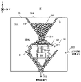
- FIG. 1 is a cross-sectional view showing the structure of the modeling system of the present embodiment.
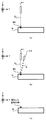
- FIGS. 2 (a) to 2 (c) are cross-sectional views each showing light irradiation and formation material supply in a certain area on the workpiece.
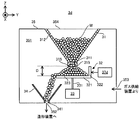
- FIG. 3 is a cross-sectional view showing the structure of the material supply device of the present embodiment.
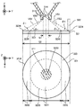
- FIG. 4 is a cross-sectional view and a plan view showing a part of the material supply device in an enlarged manner.
- FIG. 5 is a cross-sectional view showing the supply operation of the build material by the material supply device.
- FIG. 6 is a graph showing the relationship between the amplitude of vibration of the holding member and the supply amount of the forming material.
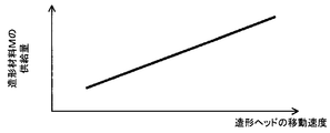
- FIG. 7 is a graph showing the relationship between the moving speed of the forming head and the supply amount of the forming material.
- FIG. 8 is a cross-sectional view showing the structure of the material supply device of the first modification.
- FIG. 9 is a cross-sectional view showing a structure of a material supply device of a second modified example.
- FIG. 10 is a cross-sectional view showing the structure of the material supply device of the third modification.
- FIG. 11 is a cross-sectional view showing the structure of the material supply device of the fourth modification.
- FIG. 12 is a cross-sectional view showing the structure of the material supply device of the fifth modification.
- FIG. 13 is a cross-sectional view showing the structure of the material supply device of the sixth modification.
- FIG. 14 is a cross-sectional view showing a structure of a material supply device of a seventh modified example.
- FIG. 15 is a cross-sectional view showing the structure of the material supply device of the eighth modification.
- each of the X-axis direction and the Y-axis direction is a horizontal direction (that is, a predetermined direction in a horizontal plane), and the Z-axis direction is a vertical direction (that is, a direction orthogonal to the horizontal plane). In the vertical direction).
- the rotational directions (in other words, the inclined directions) around the X axis, the Y axis and the Z axis are referred to as the ⁇ X direction, the ⁇ Y direction and the ⁇ Z direction, respectively.
- FIG. 1 is a cross-sectional view showing an example of the structure of a modeling system 1 of the present embodiment.
- the shaping system 1 can form a shaped object (specifically, a three-dimensional object).
- the shaping system 1 can form a shaped object on a work W as a basis for forming an object.
- the shaping system 1 can form a shaped object by performing additional processing on the workpiece W.
- the modeling system 1 can form a modeled object on the stage 43.
- the shaping system 1 can form a shaped object on the existing structure.
- the shaping system 1 may form a shaped object integrated with the existing structure.
- the operation of forming a shaped object integrated with an existing structure is equivalent to the operation of adding a new structure to the existing structure.
- the shaping system 1 may form a shaped object that can be separated from the existing structure.
- FIG. 1 shows an example in which the work W is an existing structure held by the stage 43. Also, in the following description, the description will be made using an example in which the workpiece W is an existing structure held by the stage 43.
- the shaping system 1 can form a shaped object by the laser buildup welding method. That is, it can be said that the modeling system 1 is a 3D printer that forms an object using the layered modeling technology.
- the additive manufacturing technology is also referred to as rapid prototyping, rapid manufacturing, or additive manufacturing.
- the shaping system 1 includes a material supply device 3, a shaping device 4, a light source 5, a gas supply device 6, and a control device 7, as shown in FIG.
- the material supply device 3, the modeling device 4, the light source 5, the gas supply device 6, and the control device 7 are housed in a housing C.
- the modeling apparatus 4 is accommodated in the upper space UC of the housing C, and the housing in which the material supply device 3, the light source 5, the gas supply device 6 and the control device 7 are located below the upper space UC. It is accommodated in the lower space LC of the body C.
- the arrangement positions of the material supply device 3, the modeling device 4, the light source 5, the gas supply device 6 and the control device 7 in the housing C are not limited to the arrangement positions shown in FIG. 1.
- the material supply device 3 supplies the modeling material M to the modeling device 4.
- the material supply device 3 is a desired supply according to the necessary amount so that the modeling material M is supplied to the modeling device 4 in an amount required for the modeling device 4 to form a modeled object per unit time.
- Supply molding material M at a rate. That is, the material supply device 3 supplies the modeling material M such that the supply amount of the modeling material M per unit time becomes the supply amount corresponding to the desired supply rate.
- the modeling material M is a material that can be melted by irradiation with light EL having a predetermined intensity or more.
- a modeling material M for example, at least one of a metallic material and a resinous material can be used.
- the shaping material M other materials different from metallic materials and resinous materials may be used.
- the shaping material M is a powdery or granular material. That is, the modeling material M is a granular material.
- the shaping device 4 processes the shaping material M supplied from the material supply device 3 to form a shaped object.
- the modeling apparatus 4 includes a modeling head 41, a drive system 42, and a stage 43.
- the forming head 41 includes an irradiation system 411 and a material nozzle (that is, a supply system that supplies the forming material M) 412.
- the modeling head 41, the drive system 42, and the stage 43 are accommodated in the chamber 44.
- the irradiation system 411 emits the light EL from the emission unit 411a. Specifically, the irradiation system 411 is optically connected to the light source 5 that emits the light EL via a light guide path (not shown) such as an optical fiber. The irradiation system 411 emits the light EL propagating from the light source 5 through the light guide path. The irradiation system 411 irradiates the light EL from the irradiation system 411 downward (that is, on the ⁇ Z side). Below the irradiation system 411, a stage 43 is disposed. When the work W is mounted on the stage 43, the irradiation system 411 irradiates the light EL toward the work W.
- the irradiation system 411 irradiates the workpiece W with the light EL. Furthermore, under the control of the control device 7, the state of the irradiation system 411 can be switched between the state in which the light EL is irradiated and the state in which the light EL is not irradiated.
- the material nozzle 412 has a supply outlet 412a for supplying the build material M.
- the material nozzle 412 supplies the build material M from the supply outlet 412.
- the material nozzle 412 is physically connected to the material supply device 3 which is a supply source of the forming material M via a pipe (not shown) or the like.
- the material nozzle 412 supplies the build material M supplied from the material supply device 3 at a desired supply rate via a pipe.
- the material nozzle 412 is drawn in a tube shape in FIG. 1, the shape of the material nozzle 412 is not limited to this shape.
- the material nozzle 412 supplies the build material M downward (ie, on the ⁇ Z side) from the material nozzle 412. Below the material nozzle 412, a stage 43 is disposed.
- the material nozzle 412 supplies the forming material M toward the workpiece W.
- the material nozzle 412 is aligned with the irradiation system 411 so as to supply the modeling material M toward the area (or the vicinity thereof) where the irradiation system 411 irradiates the light EL.
- the drive system 42 moves the shaping head 41.
- the drive system 42 moves the modeling head 41 along each of the X axis, the Y axis, and the Z axis.
- the drive system 42 may be moved along at least one of the ⁇ X direction, the ⁇ Y direction, and the ⁇ Z direction, in addition to each of the X axis, the Y axis, and the Z axis.
- the drive system 42 includes, for example, a motor.
- region where the modeling material M is supplied may be controllable separately.
- At least a part of the position of the ejection unit 411a, the orientation of the ejection unit 411a, the position of the supply outlet 412a, and the orientation of the supply outlet 412a may be adjustable. Further, the position of the area to be irradiated with the light EL may be adjusted by moving the optical member of the irradiation system 411.
- the stage 43 can hold the work W. Furthermore, the stage 43 can release the held work W.
- the irradiation system 411 described above irradiates the light EL in at least a part of a period in which the stage 43 holds the work W.
- the material nozzle 412 described above supplies the build material M in at least a part of a period in which the stage 43 holds the workpiece W.
- a part of the modeling material M supplied by the material nozzle 412 may scatter or spill out from the surface of the workpiece W to the outside of the workpiece W (for example, to the periphery of the stage 43).
- the shaping system 1 may be provided with a recovery device for recovering the scattered or spilled build material M around the stage 43.
- the light source 5 emits, for example, at least one of infrared light, visible light and ultraviolet light as light EL. However, other types of light may be used as the light EL.
- the light EL is a laser light.
- the light source 5 includes a laser light source (for example, a laser diode (LD: Laser Diode).
- LD Laser Diode
- the light EL may not be a laser light, and the light source 5 may be any light source (for example, LED (Light Emitting)). It may include a diode), a discharge lamp etc.).
- the gas supply device 6 is a supply source of an inert gas. Nitrogen gas or argon gas is mentioned as an example of inert gas.
- the gas supply device 6 supplies an inert gas into the chamber 44 of the modeling device 4. As a result, the internal space of the chamber 44 becomes a space purged with an inert gas.
- the gas supply device 6 further supplies an inert gas to the material supply device 3 as well.
- the inert gas supplied to the material supply device 3 is mainly used to pump the building material M, as described later. Therefore, the gas supply device 6 supplies the pressurized inert gas to the material supply device 3. Note that the gas supply to the chamber 44 and the gas supply to the material supply device 3 may be separately controlled.
- the gas supply amount per unit time to the chamber 44 and the gas supply amount per unit time to the material supply device 3 may be different.
- the gas supply to one of the chamber 44 and the material supply device 3 may be performed while the gas supply to the other is stopped.
- characteristics for example, temperature and the like
- the composition of the gas supplied to the chamber 44 and the gas supplied to the material supply device 3 may be different.
- the gas supply apparatus that supplies the gas to the chamber 44 and the gas supply apparatus that supplies the gas to the material supply apparatus 3 may be different.
- the control device 7 controls the operation of the modeling system 1.
- the control device 7 may include, for example, a central processing unit (CPU) and a memory.
- the control device 7 controls the emission mode of the light EL by the irradiation system 411.
- the emission mode includes, but is not limited to, at least one of the intensity of the light EL and the emission timing of the light EL.
- the emission mode may include at least one of the emission time of the pulsed light and the ratio (duty) of the emission time of the pulsed light to the extinction time when the light EL is pulsed light.
- the control device 7 controls the movement mode of the modeling head 41 by the drive system 42.
- the movement mode includes, but is not limited to, at least one of movement amount, movement speed, movement direction, and movement timing.
- the control device 7 controls the supply mode of the build material M by the material supply device 3. Delivery modes include, but are not limited to, delivery rates.
- the shaping system 1 forms a shaped object on the work W based on three-dimensional model data (for example, CAD (Computer Aided Design) data) of a shaped object to be formed.
- three-dimensional model data for example, measurement data of CT (Computed Tomography) and MRI (Magnetic resonance imaging) may be used.
- the modeling system 1 sequentially forms, for example, a plurality of layered partial structures (hereinafter, referred to as “structural layers”) aligned in the Z-axis direction in order to form a modeled object.
- the modeling system 1 sequentially forms a plurality of structural layers obtained by rounding the modeled object along the Z-axis direction.
- a three-dimensional object which is an assembly of a plurality of structural layers is formed.
- movement which forms a molded article by forming several structural layers one by one in order is demonstrated.
- the shaping system 1 controls the control unit 7 so as to eject a portion 411a of the irradiation system 411 with respect to a desired area on the workpiece W (specifically, an area where a structure for forming a certain structural layer is to be formed). Emits light EL.
- the condensing position of the light EL substantially coincides with the surface of the workpiece W.
- the molten pool that is, the pool of the metal melted by the light EL
- MA is formed on the work W by the light EL emitted from the emitting portion 411a of the irradiation system 411. .
- the shaping system 1 supplies the shaping material M from the material nozzle 412 to the molten pool MA as shown in FIG. 2 (b) under the control of the control device 7. As a result, the shaping material M supplied to the molten pool MA is melted. When the molten pool MA is not irradiated with the light EL with the movement of the shaping head 41, the modeling material M melted in the molten pool MA is cooled and solidified again (that is, solidified). As a result, as shown in FIG. 2 (c), the resolidified shaping material M is deposited on the work W. That is, a three-dimensional structure is formed by the deposit of the resolidified shaping material M.
- the formation of the molten pool MA by the light irradiation EL, the supply of the forming material M, the melting, and the resolidification thereof are repeated while moving the forming head 41 relative to the work W along the XY plane.
- the light EL is selectively irradiated to a region on the work W where it is desired to form a structure, while it is not selectively irradiated to the region on the work W where it is not desirable to form a structure.
- a structural layer corresponding to an aggregate of the solidified modeling material M is formed.
- the modeling system 1 performs an operation for forming such a structural layer under three-dimensional model data (in particular, three-dimensional model data corresponding to the first structural layer # 1) under the control of the control device 7. Do based on. As a result, the first structure layer # 1 is formed on the work W. Thereafter, the modeling system 1 forms a second structural layer # 2 on the workpiece W.
- the control device 7 first controls the drive system 42 so that the shaping head 41 moves along the Z-axis direction. Specifically, the control device 7 controls the drive system 42 so that the area to which the light EL is irradiated and the area to which the modeling material M is supplied are set on the surface of the first structural layer # 1. The molding head 41 is moved toward the + Z axis side.
- the condensing position of light EL substantially coincides with the surface of the structural layer # 1.
- the modeling system 1 performs an operation similar to the operation of forming the first structural layer # 1 under the control of the control device 7, based on the three-dimensional model data corresponding to the second structural layer # 2.
- the second structural layer # 2 is formed on the first structural layer # 1.
- the same operation is repeated until all structural layers constituting the object to be formed on the work W are formed.
- a three-dimensional object is formed by the assembly of the plurality of structural layers.
- the position of the shaping head 41 is changed in the Z-axis direction so that the light condensing position of the light EL substantially coincides with the lower structural layer (or the surface of the work W). It is also good.
- the condensing position of the light EL may be changed by, for example, the movement of the optical member of the irradiation system 411 without moving the modeling head 41.
- FIG. 3 is a cross-sectional view showing the structure of the material supply device 3.
- FIG. 4 is a cross-sectional view and a plan view showing a part of the material supply device 3 in an enlarged manner.
- the material supply device 3 includes a hopper 31, a holding member 32, a vibrating device 33, and a material delivery member 34.
- the hopper 31, the holding member 32, the vibrating device 33, and the material delivery member 34 are accommodated in the internal space 351 of the housing 35. Note that at least a part of the vibration device 33 may be disposed outside the housing 35.
- the hopper 31 is a device for storing the modeling material M.
- the hopper 31 has a funnel-like shape (that is, an inverted conical shape).
- a space surrounded by a partition having a funnel-like shape corresponds to the storage space 313 for storing the shaping material M.
- the hopper 31 may have another shape.
- the shape of the hopper 31 may be another shape (for example, a shape of an inverted quadrangular pyramid).
- a supply port 311 is formed at the lower end of the hopper 31 (that is, below the storage space 313).
- the supply port 311 is an opening (that is, a through hole) which penetrates the partition wall at the bottom of the hopper 31 along the Z-axis direction.
- the supply port 311 is defined by (i.e. surrounded by) the lower inner surface 314 of the hopper 31.
- the shape of the cross section of the supply port 311 (specifically, the cross section along the XY plane) is circular, but may be another shape. Other shapes include at least one of an oval, an oval and a rectangle.
- the supply port 311 is an opening for supplying the modeling material M from the hopper 31 to the lower side of the hopper 31 (that is, to the ⁇ Z side). That is, the modeling material M stored in the hopper 31 is supplied to the outside of the hopper 31 through the supply port 311 (in other words, discharged or dropped).
- An air vent 312 is formed at the top of the hopper 31.
- the storage space 313 of the hopper 31 in particular, the space above the molding material M stored in the storage space 313) and the internal space 351 of the housing 35 (in particular, the modeling material M is discharged from the hopper 31 Through the partition wall of the hopper 31 so as to connect the By forming the vent holes 312, even when the building material M is stored in the storage space 313, an imbalance between the pressure in the storage space 313 and the pressure in the internal space 351 is prevented, and from the hopper 31.
- the molding material M is supplied smoothly. As a result, the modeling material M is not suddenly supplied from the hopper 31 due to the imbalance between the pressure of the storage space 313 and the pressure of the internal space 351.
- the modeling material M is not smoothly supplied from the hopper 31 (or the modeling material M discharged from the hopper 31 has the supply port 311 It does not flow back to the storage space 313 of the hopper 31).
- the storage space 313 of the hopper 31 and the internal space 351 of the housing 35 are connected by a pipe or the like so as to eliminate the imbalance between the pressure of the storage space 313 and the pressure of the internal space 351 instead of forming the vent holes 312. You may Further, for example, when the pressure difference between the storage space 313 and the internal space 351 is small, the storage space 313 and the internal space 351 may not be connected via the vent hole 312 or the like.
- the holding member 32 holds the modeling material M supplied from the supply port 311 of the hopper 31 to the outside of the hopper 31.
- the holding member 32 is disposed below the hopper 31.
- the holding member 32 is disposed below the supply port 311.
- the holding member 32 is disposed such that a portion of the holding member 32 is located directly below the supply port 311. That is, the holding member 32 is disposed such that a part of the holding member 32 faces the supply port 311 along the Z-axis direction.
- the holding member 32 includes a bottom member 321 and a side wall member 322.
- the bottom member 321 is disposed below the hopper 31.
- the bottom member 321 is disposed below the supply port 311.
- the bottom member 321 is disposed such that a portion of the bottom member 321 is located directly below the supply port 311. That is, the bottom member 321 is disposed such that a portion of the bottom member 321 faces the supply port 311 along the Z-axis direction.
- the upper surface (that is, the surface on the + Z side) of the bottom member 321 serves as a holding surface 323 for holding the modeling material M supplied from the supply port 311.
- the holding surface 323 is disposed below the hopper 31.
- the holding surface 323 is disposed below the supply port 311.
- the holding surface 323 is disposed such that a portion of the holding surface 323 is located directly below the supply port 311. That is, the holding surface 323 is arranged such that a part of the holding surface 323 faces the supply port 311 along the Z-axis direction.
- the holding surface 323 is a plane along the XY plane (or parallel to the XY plane), and is a horizontal plane.
- the holding surface 323 is disposed at a position separated from the supply port 311 in the Z-axis direction.
- the holding surface 323 does not contact the lower end portion 3141 of the lower inner surface 314 of the hopper 31 that defines the supply port 311.
- the holding surface 323 does not contact the lower surface 315 of the hopper 31.
- the holding surface 323 does not block the supply port 311.
- the lower surface 315 of the hopper 31 may or may not be parallel to a surface (or a horizontal surface) along the XY plane.
- the size of the holding surface 323 is a size that satisfies the first condition, the second condition, and the third condition described below.
- the first condition is that the size of the holding surface 323 is larger than the cross section of the supply port 311.
- the cross section of the supply port 311 can be a cross section in a plane parallel to the holding surface 323. That is, the first condition is a condition that the area S2 of the holding surface 323 becomes larger than the cross-sectional area S1 of the supply port 311, as shown in FIG.
- the second condition extends outward from the lower end portion 3141 of the lower inner surface 314 of the hopper 31 defining the supply port 311 and enlarges the holding surface 323 (or the holding surface 323).
- the virtual surface VS2 which is a surface to be the repose angle ⁇ r of the modeling material M is described by the virtual surface VS2).
- the second condition is that the outer edge (that is, the circumference) is defined by the intersection 3230 of the holding surface 323 and the virtual surface VS2 and the holding surface 323 (or a virtual surface obtained by enlarging the holding surface 323).
- the condition is that the size of the circular area 3231 which is at the same height as the holding surface 323 is equal to or larger than the size.
- the second condition is that the holding surface 323 is large enough to include the area 3231 (that is, the area 3231 can be set on the holding surface 323). That is, the virtual surface VS2 extends from the lower end portion 3141 to the holding surface 323, and is a surface inclined with respect to the holding surface 323 such that the angle formed with the holding surface 323 is the repose angle ⁇ r of the modeling material M. It is.
- the area 3231 is substantially a circular area extending outward from the reference point 3233 (see FIG. 4) on the holding surface 323 located directly below the supply port 311 and larger than the cross section of the supply port 311. It can be said that there is.
- the repose angle ⁇ r can maintain the stability of the mountain of the modeling material M deposited on the holding surface 323 under the situation where the holding member 32 is at rest (that is, the spontaneous movement of the mountain of the modeling material M) (Does not cause a serious collapse)) is the maximum angle of the slope of the mountain. Therefore, the second condition can substantially maintain the repose angle ⁇ r of the mountain of the modeling material M deposited on the holding surface 323 under the situation where the holding member 32 is at rest (that is, the modeling material It can also be said that the condition is that the holding surface 323 becomes large to the extent that the angle of the slope of the mountain of M can be made equal to or less than the repose angle ⁇ r.
- the radius of the circular area 3231 is larger than the distance between the supply port 311 and the holding surface 323.
- the area 3231 may not be a circular area.
- a circle inscribed in the area or a circumscribed circle may be regarded as the area 3231.
- the third condition is that the holding surface 323 is large enough that the holding surface 323 can be provided with a region 3232 (see FIG. 4) extending outside the region 3231 in addition to the region 3231. That is, the third condition is that the holding surface 323 is large enough to set the area 3232 outside the area 3231.
- the holding surface 323 includes the area 3232, as is apparent from FIG. 4, the lower end portion of the hopper 31 (that is, the edge of the supply port 311) 3141 to the outer edge 3234 of the holding surface 323 (that is, the area 3232).
- An angle ⁇ 1 formed by the virtual surface VS1 which is an outer edge and is a surface extending to the end of the holding surface 323 with the holding surface 323 is equal to or less than the repose angle ⁇ r.
- the holding surface 323 can hold the modeling material M between the virtual surface VS1 and the supply port 311. Since the first condition in which the holding surface 323 is larger than the cross section of the supply port 311 is satisfied, the virtual surface VS1 is a surface inclined with respect to the holding surface 323. Furthermore, when the holding surface 323 includes the region 3232, the virtual surface VS2 is a surface that intersects the holding surface 323.
- the side wall member 322 is a member (in other words, a portion) protruding from the bottom member 321 to the + Z side. In the example shown in FIGS. 3 and 4, the side wall member 322 is formed at the outer edge 3234 (or in the vicinity thereof) of the holding surface 323.
- the sidewall member 322 is a stopper for preventing the modeling material M from spilling out (i.e., falling, hereinafter the same) from the holding surface 323 (i.e., the bottom member 321) to an unintended region outside the holding surface 323. Act as.
- the side wall member 322 guides the shaping material M on the holding surface 323 so that the modeling material M spills from the holding surface 323 (that is, the bottom member 321) to the intended area outside the holding surface 323. Function as a guide member.
- the area intended as the area where the build material M falls off is the area where the material delivery member 34 is located from the holding surface 323.
- the modeling material M held by the holding surface 323 falls from the holding surface 323 and is carried out to the material delivery member 34. For this reason, while the modeling material M is carried out from the holding surface 323 to the material delivery member 34, the side wall member 322 prevents the modeling material M from falling off from the holding surface 323 to the portion where the material delivery member 34 is not located.
- the side wall member 322 is formed in an area on the holding surface 323 (in particular, the area at or near the outer edge 3234) where the build material M should not spill out.
- the side wall member 322 is not formed in the area on the holding surface 323 (in particular, the area at or near the outer edge 3234) where the build material M is to be dropped.
- the side wall member 322 may be provided on the + X side and the ⁇ X side of the outer edge 3234 of the holding surface 323.
- at least a part of the side wall member 322 may be provided in the region 3231 on the holding surface 323.
- the vibration device 33 vibrates the holding member 32 under the control of the control device 7. Specifically, the vibration device 33 is connected to the holding member 32 (the bottom member 321 in the example shown in FIG. 3) via the vibration transmission member 331. The vibration device 33 transmits the vibration to the holding member 32 via the vibration transmission member 331. As a result, the holding member 32 vibrates.
- the vibrating device 33 may vibrate the holding member 32 along the X-axis direction, may vibrate the holding member 32 along the Y-axis direction, and vibrate the holding member 32 along the Z-axis direction. It may be made to vibrate, and it may be made to vibrate in the direction which intersects at least one of X axis, Y axis, and Z axis.
- the vibration device 33 includes, but is not limited to, an ultrasonic motor or an electromagnetic motor, and an actuator using a laminated piezoelectric element.
- the holding member 32 may be vibrated indirectly using remote force such as electromagnetic force or resonance without using the vibration transfer member 331.
- the vibration by the vibration device 33 is not limited to the periodic vibration, and may be a non-periodic vibration.
- the vibrating device 33 vibrates the holding member 32 under the control of the control device 7 to hold a part of the modeling material M held by the holding surface 323 through the outer edge 3234 of the holding surface 323. Fall outside of the That is, the vibrating device 33 vibrates the holding member 32 to hold a part of the modeling material M held by the holding surface 323 (that is, deposited on the holding surface 323) from the holding surface 323.
- the surface 323 is carried out to the outside of the holding surface 323 (specifically, the material delivery member 34).
- the vibration device 33 under the control of the control device 7, in the vibration device 33, a part of the modeling material M held by the holding surface 323 is transmitted from the holding surface 323 to the holding surface 323 and outside the holding surface 323 (specifically The holding member 32 is vibrated so as to be carried out to the material delivery member 34).
- the holding surface 323 and the supply port 311 of the hopper 31 are separated (that is, not in contact with each other). That is, the holding member 32 and the hopper 31 are separated (that is, not in contact with each other). For this reason, the vibration device 33 does not vibrate the hopper 31.
- the material delivery member 34 receives the modeling material M carried out of the holding surface 323 (that is, dropped, and so forth).
- the material delivery member 34 is disposed at a position where it can receive the modeling material M carried out of the holding surface 323 in order to receive the modeling material M carried out of the holding surface 323.
- the material delivery member 34 is located at least one of the lower side and the diagonal lower side of the holding surface 323.
- the modeling material M is carried out of the holding surface 323 so as to spill out (that is, fall) from the holding surface 323, and the material delivery member 34 is in the dropping path of the modeling material M from the holding surface 323. Be placed.
- the material delivery member 34 has a funnel-like shape (for example, an inverted conical shape) in order to properly receive the build material M carried out of the holding surface 323.
- the material delivery member 34 receives the collection of the build material M carried out of the holding surface 323 by a partition having a funnel-like shape.
- the material delivery member 34 may have another shape (e.g., an inverted quadrangular pyramid shape).
- the material delivery member 34 further delivers the modeling material M received from the holding surface 323 to the outside of the material supply device 3 (that is, to the modeling device 4).
- a delivery port 341 is formed at the lower end of the material delivery member 34 in order to deliver the modeling material M to the modeling apparatus 4.
- the delivery port 341 is an opening (i.e., a through hole) penetrating the partition wall at the bottom of the material delivery member 34 along the Z-axis direction.
- the shape of the cross section of the delivery port 341 (specifically, the cross section along the XY plane) is circular, but may be another shape. Other shapes include at least one of an oval, an oval and a rectangle.
- the housing 35 is formed with a delivery port 352.
- the delivery port 352 is in communication with the delivery port 341 of the material delivery member 34.
- the above-mentioned unshown pipe connected to the modeling device 4 is connected to the delivery port 352. Accordingly, the modeling material M delivered by the material delivery member 34 is delivered to the modeling apparatus 4 via the delivery ports 341 and 352 and a pipe (not shown).
- An inlet 353 is further formed in the housing 35.
- the inlet (air supply port) 353 is connected to the gas supply device 6 described above. Therefore, pressurized inert gas is supplied to the internal space 351 of the housing 35 from the gas supply device 6 described above via the inlet 353.
- a material replenishment port 354 is further formed in the housing 35.
- the material replenishment port 354 is an opening for replenishing the hopper 31 with the modeling material M.
- the material replenishment port 354 is normally sealed by a lid (not shown) (specifically, during a period when the hopper 31 is not replenished with the build material M). For this reason, the state of the internal space 351 is normally maintained in the pressurized state.
- the lid of the material replenishment port 354 is opened during the time of replenishing the hopper 31 with the build material M.
- the material replenishment port 354 may be used for purposes other than replenishment of the modeling material M (for example, replacement of parts disposed in the housing 35, maintenance, etc.).
- the holding surface 323 is a surface along the XY plane, and is separated from the supply port 311 (in other words, the lower surface 315 of the hopper 31) along the Z-axis direction. It is placed below. For this reason, as shown in FIG. 5, the modeling material M supplied (that is, dropped) from the supply port 311 is deposited on the holding surface 323.
- the holding surface 323 holds the modeling material M such that the modeling material M supplied from the supply port 311 is deposited on the holding surface 323.
- the holding surface 323 holds the modeling material M such that the modeling material M is held between the supply port 311 and the holding surface 323 (that is, between the lower surface 315 of the hopper 31 and the holding surface 323).
- the holding surface 323 holds the amount of the modeling material M according to the distance D between the supply port 311 and the holding surface 323. Specifically, the holding surface 323 holds a large amount of the modeling material M as the distance D between the supply port 311 and the holding surface 323 increases. That is, the amount of the modeling material M held by the holding surface 323 increases as the distance D between the supply port 311 and the holding surface 323 increases.
- the size of the holding surface 323 is a size that satisfies the first condition that the holding surface 323 becomes larger than the cross section of the supply port 311. For this reason, as shown in FIG. 5, the modeling material M supplied from the supply port 311 is deposited on the holding surface 323 so as to form a mountain of the modeling material M spreading outward from the supply port 311 downward. Be done.
- the holding surface 323 holds more modeling material M the closer to the reference point 3233 (see FIG. 4) on the holding surface 323 located directly below the supply port 311.
- the holding surface 323 holds the modeling material M such that the modeling material M is held between the supply port 311, the holding surface 323, and the virtual surface VS1 (see FIG. 4) to form a mountain of the modeling material M.
- the size of the holding surface 323 is such that the circular area 3231 can be set on the holding surface 323 (that is, deposited on the holding surface 323 in a situation where the holding member 32 stands still) To the extent that it is possible to maintain the mountain repose angle ⁇ r of the modeling material M), and the size that satisfies the second condition that the holding surface 323 becomes large.
- the holding surface 323 is a holding surface in a state where the angle between the slope of the molding material M supplied from the supply port 311 and the holding surface 323 does not exceed the repose angle ⁇ r.
- the shaping material M can be held as formed on H.323. That is, the holding surface 323 is a molding material so that the pile of the molding material M does not spontaneously collapse under the condition that the holding member 32 is stationary (that is, the vibration device 33 does not vibrate the holding member 32). M can hold.
- the size of the holding surface 323 is the third condition that the holding surface 323 is large enough to include the region 3232 which spreads outside the region 3231 in addition to the region 3231. Meet. Therefore, the holding surface 323 can hold the modeling material M using not only the region 3231 but also the region 3232. For this reason, the holding surface 323 can hold a mountain formed by the modeling material M on the holding surface 323 in a state where an angle formed by the inclined surface and the holding surface 323 is equal to or less than the repose angle ⁇ r. As a result, the holding surface 323 can hold the modeling material M such that the peaks of the modeling material M supplied from the supply port 311 become more unlikely to collapse spontaneously.
- the modeling material M supplied from the hopper 31 to the outside of the hopper 31 is temporarily held by the holding surface 323 in a stable manner.
- the modeling material M deposited on the holding surface 323 is in contact with the supply port 311, and in the situation where the holding member 32 is at rest, the deposited modeling material M blocks the supply port 311 and further modeling material M Is prevented from being supplied to the holding surface 323.
- the holding member 32 is vibrated by the vibration device 33.
- the stationary holding member 32 starts to vibrate, a part of the modeling material M constituting the mountain gradually begins to collapse from the mountain of the modeling material M which is stably held by the holding surface 323.
- a part of the modeling material M constituting the mountain gradually starts to separate from the mountain of the modeling material M which the holding surface 323 is stably held. .
- a part of the modeling material M constituting the mountain is a unit from the mountain of the modeling material M which the holding surface 323 has stably held. It will continue to collapse gradually by a fixed amount every hour.
- a part of the modeling material M constituting the mountain is for every unit time
- the building material M which has fallen or separated from the mountain falls from the holding surface 323 to the outside of the holding surface 323 (that is, the material delivery member 34).
- a fixed amount of the modeling material M is carried out to the material carry-out device 34 every unit time.
- the vibration device 33 stops, the modeling material M deposited on the holding surface 323 stops collapsing, and the modeling material M does not spill out of the holding surface 323. That is, the carrying out of the modeling material M from the holding surface 323 to the material delivery member 34 is stopped. As a result, the supply of the modeling material M from the material supply device 3 to the modeling device 4 is also stopped. Therefore, the vibration device 33 does not have to supply the modeling material M to the modeling device 4 under the control of the control device 7 (for example, at the timing when the material nozzle 412 does not have to supply the modeling material M). , Stop the vibration of the holding member 32.
- the amount of the modeling material M carried out from the holding surface 323 to the outside of the holding surface 323 per unit time (that is, the carried-out amount of the modeling material M per unit time) can be controlled in the state of vibration of the holding member 32 is there. For this reason, in the vibration device 33, the amount of the modeling material M carried out from the holding surface 323 to the material delivery member 34 per unit time under the control of the control device 7 is that of the modeling material M necessary for forming a modeling object.
- the vibration state of the holding member 32 is set so as to achieve a desired carry-out amount corresponding to the supply rate.
- the vibrating device 33 is under the control of the control device 7 while the shaping device 4 forms a shaped object (more specifically, while the material nozzle 412 continues to supply the shaping material M)
- the holding member 32 is vibrated such that the holding member 32 continues to vibrate in the set vibration state.
- a fixed amount of the modeling material M required per unit time for the modeling apparatus 4 to form a modeled object is carried out.
- the state of vibration may include, for example, the amplitude (ie intensity) of the vibration.
- the amplitude of the vibration increases, the holding surface 323 vibrates more. For this reason, the amount of the modeling material M which falls or separates per unit time from the peak of the modeling material M which the holding surface 323 was holding increases, so that the amplitude of a vibration becomes large. That is, as the amplitude of the vibration increases, the amount of the modeling material M carried out from the holding surface 323 to the outside of the holding surface 323 increases per unit time.
- the quantity of the modeling material M carried out from the holding surface 323 to the outside of the holding surface 323 per unit time increases, the quantity of modeling material M supplied from the material supply device 3 to the modeling apparatus 4 per unit time In other words, the supply amount is increased. Therefore, as shown in FIG. 6, as the amplitude of the vibration increases, the amount of supply of the modeling material M supplied from the material supply device 3 to the modeling device 4 per unit time increases.
- the control device 7 is carried out from the holding surface 323 to the material delivery member 34 per unit time, taking into consideration the relationship between the amplitude of the vibration of the holding member 32 and the supply amount of the modeling material M.
- the amplitude of the vibration of the holding member 32 is set so that the amount of the modeling material M becomes a desired carry-out amount corresponding to the supply rate of the modeling material M necessary for forming the three-dimensional object.
- the control device 7 holds the holding member 32.
- the amplitude of the vibration of is set to A1.
- the controller 7 sets the amplitude of the vibration of the holding member 32 to A2 (where A2 ⁇ A1).
- the control device 7 may set the amplitude of vibration so as to satisfy the constraint that the peaks of the modeling material M held by the holding surface 323 gradually collapse (that is, not collapse at once).
- the state of vibration may include, for example, the frequency of vibration.
- the holding surface 323 vibrates at a higher speed. For this reason, as the frequency of vibration increases, the amount of the modeling material M that falls or separates per unit time from the peak of the modeling material M held by the holding surface 323 increases. That is, as the frequency of vibration increases, the amount of the modeling material M carried out from the holding surface 323 to the outside of the holding surface 323 per unit time increases. Therefore, like the amplitude of the vibration, the amount (the amount of supply) of the modeling material M supplied from the material supply device 3 to the modeling device 4 per unit time increases as the frequency of the vibration increases.
- the control device 7 is carried out from the holding surface 323 to the material delivery member 34 per unit time in consideration of the relationship between the frequency of the vibration of the holding member 32 and the supply amount of the modeling material M.
- the frequency of vibration of the holding member 32 may be set such that the amount of the modeling material M is a desired carry-out amount corresponding to the supply rate of the modeling material M necessary for forming the three-dimensional object.
- the control device 7 may set the frequency of vibration so as to satisfy the constraint that the peaks of the modeling material M held by the holding surface 323 gradually collapse (that is, not collapse at once).
- the amount of the modeling material M in the first state to be carried out from the holding surface 323 per unit time and the unit surface 31 to be carried out per unit time There is a possibility that the amount of the modeling material M in the second state (but the second state is different from the first state) may not be the same. That is, the amount of the modeling material M in the first state carried out per unit time from the holding surface 323 vibrating in a certain state, and the second different one carried out per unit time from the holding surface 323 vibrating in the same state. The amount of the modeling material M in the state may not be the same.
- the amount of the forming material M of the second type (but the second type is different from the first type) may not be the same.
- the amount of the modeling material M having the first particle size carried out per unit time from the holding surface 323 vibrating in a certain state, and the second carried out per unit time from the holding surface 323 vibrating in the same state may not be the same.
- the amount of the modeling material M of the first shape (in particular, the outer shape) carried out per unit time from the holding surface 323 vibrating in a certain state.
- the amount of the modeling material M in the second shape (but the second shape is different from the first shape) may not be the same.
- the amount of the modeling material M having a second value (where the second value is different from the first value) of the friction coefficient of the surface may not be the same.
- the control device 7 relates the relationship between the state of the modeling material M and the supply volume of the modeling material M
- the amount of the molding material M carried out from the holding surface 323 to the material delivery member 34 per unit time is the desired carry-out amount according to the supply rate of the molding material M necessary for forming the
- the state of vibration of the holding member 32 may be set so that
- the state of the modeling material M includes at least one of the type of the modeling material M, the size (particle diameter) of the modeling material M, the shape of the modeling material M, and the friction coefficient of the surface of the modeling material M It is also good.
- the holding surface 323 holds substantially the same amount of the modeling material M. In other words, the holding surface 323 holds the amount of the molding material M according to the distance D between the lower surface 315 of the hopper 31 and the holding surface 323 regardless of the unloading of the molding material M from the holding surface 323. .
- the modeling material M carried out of the holding surface 323 falls from the holding surface 323 to the material delivery member 34.
- the material delivery member 34 receives the modeling material M carried out of the holding surface 323.
- the modeling material M received by the material delivery member 34 is delivered to the outside of the material supply device 3 (that is, to the modeling device 4).
- the inert gas pressurized from the gas supply device 6 is supplied to the internal space 351 of the housing 35 in which the material delivery member 34 is accommodated, via the inflow port 353.
- the material delivery member 34 delivers the modeling material M to the modeling apparatus 4 by pressure feeding with the inert gas.
- the modeling material M received by the material delivery member 34 is delivered so as to be pushed out in the pipe via the delivery ports 341 and 352 by the pressure of the inert gas supplied to the internal space 351.
- the shaping material M delivered through the pipe is supplied from the material nozzle 412.
- the material delivery member 34 delivers the forming material M by pumping, the amount of the forming material M delivered by the material delivery member 34 per unit time is carried out from the holding surface 323 to the material delivery member 34 per unit time. It depends on the amount of the molding material M. For this reason, the material delivery member 34 can deliver a fixed amount of the modeling material M to the modeling apparatus 4 per unit time. As a result, the material supply device 3 can supply a fixed amount of the modeling material M to the modeling device 4 per unit time. That is, in the material supply device 3, the amount of the modeling material M supplied from the material supply device 3 to the modeling device 4 per unit time is constant according to the supply rate of the modeling material M required for forming the three-dimensional object. The modeling material M can be supplied to the modeling apparatus 4 so as to obtain a desired supply amount.
- the holding member 32 disposed below the hopper 31 holds a fixed amount of the modeling material M supplied from the hopper 31, and then the unit is moved by the vibration of the holding member 32.
- a fixed amount of modeling material M is carried out from the holding surface 323 to the material delivery member 34 per hour.
- the material supply device 3 can stably supply the modeling device 4 with a fixed amount of modeling material M required per unit time for the modeling device 4 to form a modeled object. That is, the material supply device 3 can supply the modeling material M while maintaining the desired supply rate.
- the amount of the modeling material M to be carried out from the holding surface 323 to the material delivery member 34 per unit time is constant. That is, while the modeling apparatus 4 forms a modeling object, the quantity of modeling material M supplied to the modeling apparatus 4 from the material supply apparatus 3 per unit time is constant. However, under the control of the control device 7, the material supply device 3 supplies the modeling material M supplied from the material supply device 3 to the modeling device 4 per unit time while the modeling device 4 is forming a modeled object. You may change the amount of Specifically, as described above, the amount of the modeling material M carried out from the holding surface 323 to the material delivery member 34 per unit time depends on the state of vibration of the holding member 323.
- control device 7 may control the vibration device 33 so as to change the vibration state of the holding member 32 while the modeling device 4 forms a modeled object.
- the control device 7 may control the vibration device 33 so as to change the vibration state of the holding member 32 while the modeling device 4 forms a modeled object.
- the control device 7 is carried out from the material supply device 3 to the modeling device 4 per unit time based on the traveling speed of the modeling head 41 (that is, information on the traveling speed of the modeling head 41).
- the amount of the molding material M is changed. Specifically, the time during which the material nozzle 412 supplies the forming material M to a certain unit area on the work W (or a certain unit area on the structural layer already formed on the work W, and the same applies hereinafter) The faster the moving speed of the head 41, the shorter it becomes.
- the faster the moving speed of the forming head 41 the smaller the amount of the forming material M supplied to the unit area.
- the control device 7 supplies the material per unit time based on the moving speed of the forming head 41 so that the amount of the forming material M supplied to each of the plurality of unit areas on the work W becomes the same. You may change the quantity of the modeling material M supplied from three. Specifically, as shown in FIG.
- the control device 7 supplies the amount of the forming material M supplied from the material supply device 3 per unit time (that is, per unit time).
- the supply amount of the build material M per unit time may be changed so that the supply amount of the build material M is increased.
- control apparatus 7 is not limited to the scene mentioned above, and based on at least one of the information on the moving speed of the modeling head 41 and the information on the irradiation of the light EL, the material supply apparatus 3 to the modeling apparatus 4 per unit time. You may change the quantity of the modeling material M carried out.
- strength of light EL, the irradiation position of light EL, the irradiation timing of light EL, etc. are mention
- the control device 7 may change the amount of the modeling material M carried out from the material supply device 3 to the modeling device 4 per unit time in accordance with the change in the intensity of the light EL.
- the control device 7 may change the amount of the modeling material M carried out from the material supply device 3 to the modeling device 4 per unit time in accordance with the change in the irradiation timing of the light EL.
- control unit 7 controls the holding surface 323 so that the amount of the modeling material M supplied from the material supply device 3 increases per unit time as the moving speed of the modeling head 41 increases. I changed the state of vibration. However, from the upper limit of the amplitude or frequency at which the vibration device 33 can vibrate the holding surface 323, the supply amount of the modeling material M per unit time that can be supplied to the modeling device 4 is calculated back based on the supply amount. The upper limit of the moving speed of the forming head 41 in the device 4 may be set.
- the molding system 1a according to the first modification differs from the above-described molding system 1 in that the material supply apparatus 3 is replaced with a material supply apparatus 3a.
- Other configurations of the modeling system 1 a may be the same as other configurations of the modeling system 1. Therefore, the material supply device 3a of the first modification will be described below with reference to FIG.
- the material supply device 3 a differs from the above-described material supply device 3 in that the conveyance member 36 a is further provided in the internal space 351 of the housing 35.
- the other configuration of the material supply device 3 a may be the same as the other configuration of the material supply device 3.
- the transport member 36 a receives the modeling material M carried out of the holding surface 323. Further, the transport member 36 a carries out the modeling material M received from the holding surface 323 to the material delivery member 34. Therefore, in the first modification, the modeling material M is supplied from the hopper 31 to the outside of the material supply device 3 (that is, the modeling device 4) via the holding member 32, the transport member 36a and the material delivery member 34 in this order. Be done.
- the transport member 36 a is disposed at a position capable of receiving the modeling material M unloaded from the holding surface 323 in order to receive the modeling material M unloaded (that is, dropped) from the holding surface 323.
- the transport member 36 a is located at least one of the lower side and the diagonal lower side of the holding surface 323.
- the modeling material M is carried out of the holding surface 323 so as to spill out (that is, falls) from the holding surface 323, and the transport member 36a is disposed in the falling path of the modeling material M from the holding surface 323. Be done.
- the transport member 36a receives the build material M on the top surface (that is, the surface facing the + Z side) 361a. That is, the modeling material M falls from the holding surface 323 to the upper surface 361a.
- the upper surface 361a is a surface inclined with respect to the XY plane which is a horizontal surface (that is, intersects the XY plane).
- the upper surface 361 a is a surface inclined with respect to the holding surface 323. Since the upper surface 361a is inclined, the modeling material M received by the upper surface 361a rolls off the upper surface 361a.
- a material delivery member 34 is disposed on at least one of the lower side and the lower side of the upper surface 361a.
- the material delivery member 34 is disposed on the path where the modeling material M rolls down from the upper surface 361a. For this reason, the material delivery member 34 receives the shaping material M rolling down on the upper surface 361a. That is, in the first modification, the transport member 36a causes the modeling material M received from the holding surface 323 by the upper surface 361a to fall from the upper surface 361a to the outside of the upper surface 361a (that is, And the material delivery member 34).
- Such a material supply device 3a can receive the same effects as the effects that can be obtained by the material supply device 3 described above. Furthermore, in the first modification, the modeling material M carried out from the holding surface 323 to the transport member 36a rolls off the top surface 361a due to the inclination of the top surface 361a of the transport member 36a. At this time, a frictional force from the upper surface 361a acts on the modeling material M. For this reason, the modeling material M rolls down the upper surface 361a stably at a substantially constant speed.
- the transport member 36a transfers the material delivery member 34 from the upper surface 361a per unit time rather than the fluctuation (in other words, pulsation) of the amount of the modeling material M carried out from the holding surface 323 to the transport member 36a per unit time.
- the fluctuation of the quantity of the modeling material M to be carried out can be reduced.
- the transport member 36a carries out the modeling material M so as to reduce (or suppress or cancel) the fluctuation of the amount of the modeling material M carried out from the holding surface 323 to the transportation member 36a per unit time.
- the material supply device 3a can reduce the fluctuation of the amount of the modeling material M supplied from the material supply device 3a to the modeling device 4 per unit time. Therefore, the material supply device 3 can supply the modeling material M while maintaining the desired supply rate more appropriately.
- the inclination angle of the upper surface 361a with respect to the XY plane is set to an appropriate angle that can exert an effect of reducing the fluctuation of the amount of the modeling material M carried out from the holding surface 323 to the transport member 36a per unit time. It is also good.
- An example of such an angle is an angle of 30 degrees or less (in particular, an angle of 20 degrees or less).
- the inclination angle of the upper surface 361a with respect to the XY plane may be set to an appropriate angle such that the modeling material M carried out from the holding surface 322 to the transport member 36a can properly fall over the upper surface 361a.
- the surface of the upper surface 361a may be subjected to surface processing to adjust the coefficient of friction with the modeling material M so that the modeling material M can fall properly.
- the surface processing includes at least a process of changing the coefficient of friction between the modeling material M and the surface of the upper surface 361a.
- a part of the upper surface 361 of the transport member 36a may be a surface (that is, a horizontal surface) along the XY plane. At least a portion of the upper surface 361a may be a curved surface.
- the transport member 36 a may be disposed at any position as long as the modeling material M received from the holding surface 323 can be received and the modeling material M received can be transported to the material delivery member 34.
- the material supply device 36a may include a plurality of transport members 36a.
- the modeling material M is supplied from the hopper 31 to the outside of the material supply device 3 (that is, the modeling device 4) via the holding member 32, the transport member 36a and the material delivery member 34 in this order.
- the plurality of transport members 36a are a first transport member 36a that is inclined at a first inclination angle with respect to the holding surface 323, and a second inclination angle that is different from the first inclination angle with respect to the holding surface 323 And a second transport member 36a that is inclined.
- the plurality of transport members 36 a may include at least two transport members 36 a inclined at the same inclination angle with respect to the holding surface 323.
- the molding system 1b of the second modification differs from the above-described molding system 1 in that the material supply device 3 is replaced with the material supply device 3b.
- Other configurations of the modeling system 1 b may be the same as other configurations of the modeling system 1. Therefore, below, the material supply apparatus 3b of a 2nd modification is demonstrated, referring FIG.
- the material supply device 3b differs from the material supply device 3a described above in that the vibration device 33 vibrates the transport member 36a.
- the other configuration of the material supply device 3b may be the same as the other configuration of the material supply device 3a.
- the vibrating device 33 is connected to the transport member 32 via the vibration transfer member 332 b.
- the vibration device 33 transmits the vibration to the transport member 36a via the vibration transmission member 332b.
- the transport member 36a vibrates.
- the vibrating device 33 may vibrate the transport member 36a along the X-axis direction, may vibrate the transport member 36a along the Y-axis direction, and vibrate the transport member 36a along the Z-axis direction. You may
- the transport member 36a since the transport member 36a vibrates, the modeling material M carried out from the holding surface 322 to the transport member 36a stagnates on the upper surface 361a as compared with the case where the transport member 36a does not vibrate. There is less chance of doing so. That is, in the second modification, the transport member 36a can carry out the modeling material M so that the modeling material M properly falls on the upper surface 361a.
- the vibrating device 33 for vibrating the holding member 32 vibrates the transport member 36a.
- the material supply device 3b may be separately and independently provided with a vibrating device 33b that vibrates the transport member 36a.
- the molding system 1c of the third modification differs from the above-described molding system 1 in that the material supply device 3 is replaced with the material supply device 3c.
- the other configuration of the modeling system 1 c may be the same as the other configuration of the modeling system 1. Therefore, the material supply device 3c of the third modification will be described below with reference to FIG.
- the material supply device 3c differs from the material supply device 3b described above in that the holding member 32 and the transport member 36a are integrated.
- the other configuration of the material supply device 3b may be the same as the other configuration of the material supply device 3b. Even with such a material supply device 3c, it is possible to receive the same effects as the effects that can be obtained by the material supply device 3b described above.
- a molding system 1d of the fourth modification differs from the above-described molding system 1 in that a material supply device 3d is provided instead of the material supply device 3.
- the other configurations of the modeling system 1 d may be the same as the other configurations of the modeling system 1. Therefore, the material supply device 3d of the fourth modified example will be described below with reference to FIG.
- the material supply device 3d differs from the material supply device 3 described above in that it includes a distance adjustment device 37d.
- the other configuration of the material supply device 3 d may be the same as the other configuration of the material supply device 3.
- the distance adjusting device 37 d can adjust the distance D between the supply port 311 of the hopper 31 and the holding surface 323 of the holding member 32 under the control of the control device 7. That is, under the control of the control device 7, the distance adjustment device 37d measures the distance between the lower surface 315 of the hopper 31 and the holding surface 323 (that is, the distance between the lower end 3141 of the hopper 31 and the holding surface 323) D Is adjustable.
- the distance adjusting device 37 d adjusts the distance D by moving the holding member 32 relative to the hopper 31 under the control of the control device 7.
- the distance adjustment device 37d may adjust the distance D by moving the holding member 32 along the Z axis. In this case, when the holding member 32 moves to the + Z side, the distance D decreases. On the other hand, when the holding member 32 moves to the ⁇ Z side, the distance D becomes large.
- the distance adjustment device 37d may adjust the distance D by moving the hopper 31 along the Z axis in addition to or instead of moving the holding member 32 along the Z axis. In this case, when the hopper 31 moves to the + Z side, the distance D increases.
- the distance adjustment device 37 d may include, for example, an actuator or the like in order to move at least one of the holding member 32 and the hopper 31.
- the distance adjustment device 37 d may include a measurement device that measures the distance D in order to adjust the distance D.
- the measuring device which measures the distance D includes, for example, but not limited to, an optical sensor, an electrostatic sensor or a magnetic sensor.
- the holding surface 323 holds the modeling material M in an amount corresponding to the distance D between the supply port 311 and the holding surface 323. That is, the amount of the modeling material M held by the holding surface 323 increases as the distance D between the supply port 311 and the holding surface 323 increases. Therefore, the control device 7 may adjust the amount of the modeling material M held by the holding member 32 by controlling the distance adjusting device 37 d so as to adjust the distance D.
- the control device 7 needs the amount of the modeling material M to be carried out from the holding surface 323 to the material delivery member 34 per unit time based on the state of the vibration of the holding member 32 for forming a shaped object.
- the distance D may be set so as to obtain a desired carry-out amount corresponding to the supply rate of the modeling material M.
- the control device 7 supplies the distance D and the supply amount of the modeling material M (that is, the material supply device 3 per unit time), as in the case of setting the vibration state (for example, amplitude or frequency) of the holding member 32.
- the control device 7 may control the distance adjustment device 37 d such that the supply port 311 and the holding surface 323 are separated along the Z axis by the set distance D.
- the control device 7 carries out the transfer from the holding surface 323 to the material delivery member 34 per unit time by adjusting (that is, changing) the distance D while the modeling device 4 forms a modeled object.
- the amount of shaping material M to be made may be changed.
- the amount of the modeling material M to be carried out from the material supply device 3 to the modeling device 4 per unit time is changed.
- an example of the scene which changes the quantity of the modeling material M supplied from the material supply apparatus 3 per unit time is as having mentioned above already.
- the material supply device 3 d can more appropriately supply the modeling material M to the modeling device 4.
- a molding system 1e of the fifth modification is different from the above-described molding system 1 in that a material supply device 3e is provided instead of the material supply device 3.
- Other configurations of the modeling system 1 e may be the same as other configurations of the modeling system 1. Therefore, the material supply device 3e of the fifth modification will be described below with reference to FIG.
- the material supply device 3e differs from the material supply device 3a described above in that it includes an angle adjustment device 38e.
- the other configuration of the material supply device 3e may be the same as the other configuration of the material supply device 3a.
- the angle adjustment device 38e can adjust the inclination angle of the upper surface 361a with respect to the XY plane (that is, the horizontal surface or the inclination angle of the upper surface 361a with respect to the holding surface 323) ⁇ under the control of the control device 7.
- the angle adjustment device 38 e adjusts the inclination angle ⁇ by moving the transport member 36 a with respect to the holding member 32 under the control of the control device 7.
- the angle adjustment device 38e may adjust the inclination angle ⁇ by rotating the transport member 36a around a rotation axis (for example, a rotation axis along the X axis) along the XY plane.
- the angle adjustment device 38e may adjust the inclination angle ⁇ by moving the transport member 36a along at least one of the ⁇ X direction and the ⁇ Y direction.
- the angle adjustment device 37d may include, for example, an actuator or the like in order to move the transport member 36a.
- the angle adjustment device 37 d may include a measurement device that measures the inclination angle ⁇ in order to adjust the inclination angle ⁇ .
- the measuring device which measures inclination angle (theta) is an inclination sensor or a rotary potentiometer, for example.
- the state of vibration of the holding member 32 is constant, if the inclination angle ⁇ of the conveying member 36a becomes constant, it is carried out from the holding surface 323 to the material delivery member 34 via the conveying member 36a per unit time.
- the amount of the molding material M becomes constant.
- the state of vibration of the holding member 32 changes, if the inclination angle ⁇ of the conveying member 36a changes according to the state of vibration, the material delivery member from the holding surface 323 through the conveying member 36a per unit time.
- the quantity of the modeling material M carried out to 34 may be constant.
- the control device 7 forms the amount of the modeling material M which is carried out from the holding surface 323 to the material delivery member 34 via the transport member 36a per unit time based on the state of vibration of the holding member 32.
- the inclination angle ⁇ may be set so as to obtain a desired carry-out amount in accordance with the supply rate of the modeling material M necessary for forming the object.
- the control device 7 supplies the inclination angle ⁇ and the supply amount of the modeling material M (that is, the material supply device per unit time) as in the case of setting the vibration state (for example, amplitude or frequency) of the holding member 32.
- the control device 7 may control the angle adjustment device 38e such that the upper surface 361a is inclined with respect to the XY plane at the set inclination angle ⁇ .
- the control device 7 adjusts (that is, changes) the inclination angle ⁇ while the modeling device 4 is forming a modeled object, from the holding surface 323 to the conveying member 36a per unit time.
- the amount of the molding material M to be carried out to the material delivery member 34 may be changed.
- the amount of the modeling material M to be carried out from the material supply device 3 to the modeling device 4 per unit time is changed.
- an example of the scene which changes the quantity of the modeling material M supplied from the material supply apparatus 3 per unit time is as above-mentioned.
- the material supply device 3e can more appropriately supply the modeling material M to the modeling device 4 by adjusting the inclination angle ⁇ .
- the molding system 1f of the sixth modification differs from the above-described molding system 1 in that the material supply device 3 is replaced with a material supply device 3f.
- Other configurations of the modeling system 1 f may be the same as other configurations of the modeling system 1. Therefore, the material supply device 3f of the sixth modification will be described below with reference to FIG.
- the material supply device 3 f is different from the above-described material supply device 3 in that a rotating device 39 f is provided instead of the vibrating device 33.
- the other configuration of the material supply device 3 f may be the same as the other configuration of the material supply device 3.
- at least a part of the rotation device 39 f may be disposed outside the housing 35.
- the rotation device 39 f rotates the holding member 32 about the rotation axis intersecting (e.g., orthogonal to) the holding surface 323 under the control of the control device 7. Specifically, the rotating device 39f is connected to the holding member 32 (the bottom member 321 in the example shown in FIG. 13) via the connecting member 391f. The rotating device 39f rotates the holding member 32 by rotating the connecting member 391f.
- the rotating device 39 f rotates the holding member 32 under the control of the control device 7 to make a part of the modeling material M held by the holding surface 323 from the holding surface 323 to the outside of the holding surface 323 (specifically, To the material delivery member 34). That is, under the control of the control device 7, in the rotation device 39f, a part of the modeling material M held by the holding surface 323 is outside the holding surface 323 from the holding surface 323 (specifically, the material delivery member 34) The holding member 32 is rotated so as to be carried out to 34).
- the holding surface 323 and the supply port 311 of the hopper 31 are separated (that is, not in contact with each other). That is, the holding member 32 and the hopper 31 are separated (that is, not in contact with each other). Therefore, the rotating device 39 f does not rotate the hopper 31.
- a part of the modeling material M constituting the mountain gradually begins to collapse from the mountain of the modeling material M which is stably held by the holding surface 323.
- a part of the modeling material M constituting the mountain gradually starts to separate from the mountain of the modeling material M which the holding surface 323 is stably held.
- a part of the modeling material M constituting the mountain is a unit from the mountain of the modeling material M which the holding surface 323 has stably held. It will continue to collapse gradually by a fixed amount every hour.
- the amount of the modeling material M carried out from the holding surface 323 to the outside of the holding surface 323 per unit time (that is, the carried-out amount of the modeling material M per unit time) can be controlled in the state of rotation of the holding member 32 is there.
- the rotating device 39f is configured such that the amount of the modeling material M carried out from the holding surface 323 to the material delivery member 34 per unit time under the control of the controller 7
- the state of rotation of the holding member 32 is set so as to achieve a desired carry-out amount corresponding to the supply rate.
- the rotating device 39f The holding member 32 is rotated so that the holding member 32 continues to rotate in the set rotation state. As a result, from the holding surface 323 to the material delivery member 34, a fixed amount of the modeling material M required per unit time for the modeling apparatus 4 to form a modeled object is carried out.
- the state of rotation may include, for example, the speed of rotation.
- the higher the speed of rotation the larger the amount of build material M that falls or separates per unit time from the pile of build material M held by the holding surface 323.
- the amount of the modeling material M which is carried out from the holding surface 323 to the outside of the holding surface 323 per unit time increases. That is, as the speed of rotation increases, the amount (that is, the supply amount) of the modeling material M supplied from the material supply device 3 to the modeling device 4 per unit time increases.
- the control device 7 is carried out from the holding surface 323 to the material delivery member 34 per unit time in consideration of the relationship between the speed of rotation of the holding member 32 and the supply amount of the modeling material M.
- the speed of rotation of the holding member 32 is set such that the amount of the modeling material M is a desired carry-out amount corresponding to the supply rate of the modeling material M necessary for forming the three-dimensional object.
- control device 7 may set the speed of rotation so as to satisfy the restriction that the pile of the modeling material M held by the holding surface 323 gradually collapses (that is, does not collapse at once).
- the controller 7 adds the state of the modeling material M and the modeling material M in addition to or in place of the relationship between the rotation state of the holding member 32 and the supply amount of the modeling material M.
- the amount of the modeling material M carried out from the holding surface 323 to the material delivery member 34 per unit time is the feeding rate of the modeling material M necessary for the formation of the modeling object
- the state of rotation of the holding member 32 may be set so as to achieve the desired carry-out amount according to the above.
- the modeling material M carried out of the holding surface 323 falls from the holding surface 323 to the material delivery member 34.
- the modeling material M is not always dropped from the holding surface 323 in the same direction.
- the material delivery member 34 has an appropriate size so as to be able to receive the forming material M falling radially, in all directions, or in all directions from the holding surface 323. And placed in the appropriate position.
- the holding member 32 forms the forming material on the holding surface 323.
- the side wall member 322 functioning as a guide member for guiding M may not be provided.
- the material supply device 3f a part of the modeling material M held by the holding surface 323 is replaced with the rotating device 39f from the holding surface 323 to the outside of the holding surface 323 (specifically, the material delivery member 34). It may be equipped with any driving device capable of moving the holding member 32 so as to be carried out. Furthermore, in this case, the control device 7 controls the state of movement of the holding member 32 to control the amount of the modeling material M carried out from the holding surface 323 to the outside of the holding surface 323 per unit time. May be Even in this case, the material supply device 3 f can receive the same effects as the effects that can be obtained by the material supply device 3 described above.
- the material supply device 3f may include the above-described vibrating device 33.
- the rotation device 39 f may be capable of vibrating the holding member 33 as in the case of the vibration device 33 described above. In this case, the holding member 32 may rotate simultaneously with vibration.
- the molding system 1g of the seventh modification differs from the above-described molding system 1 in that the material supply device 3 is replaced with a material supply device 3g.
- Other configurations of the modeling system 1 g may be the same as other configurations of the modeling system 1. Therefore, the material supply device 3g of the seventh modification will be described below with reference to FIG.
- the material supply device 3g differs from the above-described material supply device 3f in that it includes the transport member 36a.
- the other configuration of the material supply device 3g may be the same as the other configuration of the material supply device 3f.
- the conveyance member 36a since the conveyance member 36a has already been described in the first modification and the like, the detailed description thereof will be omitted.
- the transport member 36a has an appropriate size so as to be able to receive the modeling material M falling radially, in all directions, or in all directions from the holding surface 323 and Be placed in the proper position.
- a molding system 1h of the eighth modified example is different from the above-described molding system 1 in that a material supply device 3h is provided instead of the material supply device 3.
- Other configurations of the modeling system 1 h may be the same as other configurations of the modeling system 1. Therefore, the material supply device 3h of the eighth modification will be described below with reference to FIG.
- the material supply device 3 h differs from the material supply device 3 described above in that the bottom member 321 may not be opposed to the supply port 311 along the Z-axis direction.
- the material supply device 3 h differs from the material supply device 3 described above in that the holding surface 323 does not have to face the supply port 311 along the Z-axis direction.
- the material supply device 3 h includes a guide member 30 h that guides the modeling material M supplied from the supply port 311 to the holding surface 323.
- the other configuration of the material supply device 3 h may be the same as the other configuration of the material supply device 3.
- the guide member 30h includes an upper surface 301h. A portion of the upper surface 301 h faces the supply port 311 along the Z-axis direction. The end 302 h of the upper surface 301 h is disposed above the holding surface 323. The upper surface 301 h is inclined with respect to the horizontal surface so as to be lowered from the supply port 311 toward the holding surface 323. As a result, the modeling material M supplied from the supply port 311 falls on the upper surface 301 h and then slides down on the upper surface 301 h and then drops from the end portion 302 h of the upper surface 301 h to the holding surface 323.
- the modeling material M dropped from the upper surface 301h expands outward as it goes downward from the edge 302h. It is deposited on the holding surface 323 so as to form a mountain of M.
- the mountain of the modeling material M dropped from the upper surface 301h is formed by the inclined surface (specifically, the inclined surface from the lower end portion 3141 of the supply port 311 to the holding surface 323) and the holding surface 323.
- the shaping material M can be held so that the angle is formed on the holding surface 323 with the angle not exceeding the repose angle ⁇ r.
- the holding surface 323 can hold the modeling material M so that the mountain of the modeling material M does not collapse spontaneously under the situation where the holding member 32 stands still. Furthermore, because the pile of the modeling material M does not collapse spontaneously under the situation where the holding member 32 is at rest, the deposits are deposited on the upper surface 301 h and the holding surface 323 when the holding member 32 is at rest.
- the modeling material M can block the supply port 311 to suppress that the further modeling material M is supplied to the upper surface 301 h (further, it is supplied to the holding surface 323 via the upper surface 301 h).
- the holding member 32 does not necessarily have to face the supply port 311, so the degree of freedom in the arrangement of the holding member 32 is increased.
- the structure, the shape, and the arrangement of the guide member 30h illustrated in FIG. 16 are merely examples, and the guide member 30h having an arbitrary structure and shape may be arranged at an arbitrary position. Even in this case, as long as the guide member 30 h can guide the modeling material M supplied from the supply port 311 to the holding surface 323, the above-described effects can be obtained.
- the size of the holding surface 323 is set to such an extent that the holding surface 323 can be provided with a region 3232 which spreads outside the region 3231 in addition to the region 3231.
- the third condition of becoming large is satisfied.
- the size of the holding surface 323 may not satisfy the third condition. That is, the holding surface 323 may not be provided with the area 3232 extending to the outside of the area 3231.
- the holding surface 323 is a mountain formed by the modeling material M on the holding surface 323, and the slope of the mountain is the holding surface. It becomes possible to hold in a state where the angle with H.323 becomes the repose angle ⁇ r. Therefore, the holding surface 323 can hold the modeling material M such that a peak of the modeling material M formed on the holding surface 323, which is supplied from the supply port 311, does not spontaneously collapse.
- the holding member 32 includes the side wall member 322.
- the holding member 32 may not include the side wall member 322.
- the material delivery member 34 has an appropriate size so as to be able to receive the forming material M falling from the holding surface 323 radially, in all directions, or in all directions. And it is placed at an appropriate position.
- the holding member 32 (or the bottom member 321) receives the modeling material M supplied from the hopper 31, the holding member 32 (or the bottom member 321) may be called a material receiving member. Also, the holding surface 323 may be called a material receiving surface.
- the holding surface 323 is a surface parallel to the XY plane, but it may be a curved surface or may have asperities.
- the modeling apparatus 4 includes the drive system 42 for moving the modeling head 41.
- the modeling apparatus 4 may include a drive system that moves the stage 43 in addition to or instead of the drive system 42.
- the stage 43 may be movable in at least one of the X-axis direction, the Y-axis direction, the Z-axis direction, the ⁇ X direction, the ⁇ Y direction, and the ⁇ Z direction.
- the control device 7 supplies the material per unit time based on the moving speed of the stage 43 so that the amounts of the modeling material M supplied to each of the plurality of unit areas on the workpiece W become the same. You may change the quantity of the modeling material M supplied to the modeling apparatus 4 from three.
- the control device 7 supplies the amount of the modeling material M supplied from the material supply device 3 to the modeling device 4 per unit time (that is, of the modeling material M per unit time).
- the supply amount of the modeling material M per unit time may be changed so as to increase the supply amount).
- the amount of the modeling material M which the material delivery member 34 delivers per unit time is transferred from the holding surface 323 to the material delivery member 34 per unit time. It depends on the amount of the molding material M to be carried out. However, when the material supply device 3 is disposed above the shaping device 4 and the material delivery member 34 delivers the formation material M by gravity, the amount of the formation material M delivered by the material delivery member 34 per unit time can be Depending on the amount of the molding material M to be carried out from the holding surface 323 to the material delivery member 34, it may be dependent.
- the modeling apparatus 4 melts the modeling material M by irradiating the modeling material M with the light EL.
- the modeling apparatus 4 may melt the modeling material M by irradiating the modeling material M with an arbitrary energy beam.
- the modeling apparatus 4 may be equipped with a beam irradiation apparatus capable of irradiating an arbitrary energy beam in addition to or instead of the irradiation system 411.
- the optional energy beam includes, but is not limited to, charged particle beam such as electron beam, ion beam or electromagnetic wave.
- the shaping system 1 can form a shaped object by a laser buildup welding method.
- the shaping system 1 may form the shaped object from the shaped material M by another method capable of forming the shaped object from the powdered or granular shaped material M.
- powder bed fusion bonding method such as powder sinter layered manufacturing method (SLS: Selective Laser Sintering), binder injection method (Binder Jetting), or laser metal fusion method (LMF: Laser Metal Fusion.
- SLS powder sinter layered manufacturing method
- Binder injection method Binder injection method
- LMF Laser Metal Fusion
- the material supply device 3 described above may be used to supply the powdery or granular shaped material M.
- the shaping system 1 capable of forming a shaped object from the shaping material M includes the material supply device 3.
- a processable processing system using any particulate material may include the material supply device 3 that supplies the optional particulate material in place of the shaping material M.
- An example of such a processing system is a drug production system for producing a drug from a granular or powdery raw material.
- the material supply device 3 supplies granular or powdery raw material.
- the material supply device 3 supplies granular or powdery raw material.
- a processing system there is a recycling production system for producing a plastic bottle or a glass container (or other various products) from regenerated pellets obtained by finely crushing a plastic bottle or a glass container.
- the material supply device 3 supplies regenerated pellets.
- an example of such a processing system is an electronic product manufacturing system that manufactures an electronic product from minute parts. In this case, the material supply device 3 supplies minute parts.
Landscapes
- Engineering & Computer Science (AREA)
- Mechanical Engineering (AREA)
- Physics & Mathematics (AREA)
- Optics & Photonics (AREA)
- Chemical & Material Sciences (AREA)
- Materials Engineering (AREA)
- Manufacturing & Machinery (AREA)
- Plasma & Fusion (AREA)
- Robotics (AREA)
Abstract
Appareil d'alimentation pourvu : d'une source d'alimentation comprenant un orifice d'alimentation pour apporter des matériaux granulaires en poudre ; d'un élément de maintien espacé vers le bas de l'orifice d'alimentation et comprenant une surface de maintien pour maintenir les matériaux granulaires en poudre apportés depuis l'orifice d'alimentation ; et d'un premier dispositif d'entraînement 1 pour déplacer la surface de maintien, la surface de maintien étant déplacée par le premier dispositif d'entraînement 1, et une partie des matériaux granulaires en poudre maintenus selon l'angle de repos sur la surface de maintien étant lâchés à partir de la surface de maintien.
Applications Claiming Priority (2)
| Application Number | Priority Date | Filing Date | Title |
|---|---|---|---|
| JP2017-191057 | 2017-09-29 | ||
| JP2017191057 | 2017-09-29 |
Publications (1)
| Publication Number | Publication Date |
|---|---|
| WO2019065713A1 true WO2019065713A1 (fr) | 2019-04-04 |
Family
ID=65903134
Family Applications (1)
| Application Number | Title | Priority Date | Filing Date |
|---|---|---|---|
| PCT/JP2018/035640 Ceased WO2019065713A1 (fr) | 2017-09-29 | 2018-09-26 | Appareil d'alimentation, système de traitement et procédé de traitement |
Country Status (2)
| Country | Link |
|---|---|
| TW (1) | TW201922600A (fr) |
| WO (1) | WO2019065713A1 (fr) |
Cited By (2)
| Publication number | Priority date | Publication date | Assignee | Title |
|---|---|---|---|---|
| WO2021002365A1 (fr) * | 2019-07-01 | 2021-01-07 | 株式会社ニコン | Dispositif de moulage |
| WO2021019644A1 (fr) * | 2019-07-29 | 2021-02-04 | 株式会社ニコン | Système de traitement, procédé de traitement, dispositif de commande, programme informatique, support d'enregistrement et appareil de traitement |
Citations (5)
| Publication number | Priority date | Publication date | Assignee | Title |
|---|---|---|---|---|
| JPH01103632U (fr) * | 1987-12-26 | 1989-07-13 | ||
| JP2003237886A (ja) * | 2002-02-18 | 2003-08-27 | Iwatani Internatl Corp | 粒状ドライアイスの分配供給装置、及び粒状ドライアイスの連続供給システム |
| JP2011219157A (ja) * | 2010-04-14 | 2011-11-04 | Furukawa Mfg Co Ltd | 粉粒体供給装置 |
| JP5310031B2 (ja) * | 2009-01-28 | 2013-10-09 | 株式会社Ihi | テーブルフィーダ |
| WO2017061339A1 (fr) * | 2015-10-06 | 2017-04-13 | 花王株式会社 | Dispositif de pulvérisation de matière particulaire, procédé de pulvérisation de matière particulaire, et procédé de production d'un article contenant une matière particulaire |
-
2018
- 2018-09-26 WO PCT/JP2018/035640 patent/WO2019065713A1/fr not_active Ceased
- 2018-09-28 TW TW107134236A patent/TW201922600A/zh unknown
Patent Citations (5)
| Publication number | Priority date | Publication date | Assignee | Title |
|---|---|---|---|---|
| JPH01103632U (fr) * | 1987-12-26 | 1989-07-13 | ||
| JP2003237886A (ja) * | 2002-02-18 | 2003-08-27 | Iwatani Internatl Corp | 粒状ドライアイスの分配供給装置、及び粒状ドライアイスの連続供給システム |
| JP5310031B2 (ja) * | 2009-01-28 | 2013-10-09 | 株式会社Ihi | テーブルフィーダ |
| JP2011219157A (ja) * | 2010-04-14 | 2011-11-04 | Furukawa Mfg Co Ltd | 粉粒体供給装置 |
| WO2017061339A1 (fr) * | 2015-10-06 | 2017-04-13 | 花王株式会社 | Dispositif de pulvérisation de matière particulaire, procédé de pulvérisation de matière particulaire, et procédé de production d'un article contenant une matière particulaire |
Cited By (2)
| Publication number | Priority date | Publication date | Assignee | Title |
|---|---|---|---|---|
| WO2021002365A1 (fr) * | 2019-07-01 | 2021-01-07 | 株式会社ニコン | Dispositif de moulage |
| WO2021019644A1 (fr) * | 2019-07-29 | 2021-02-04 | 株式会社ニコン | Système de traitement, procédé de traitement, dispositif de commande, programme informatique, support d'enregistrement et appareil de traitement |
Also Published As
| Publication number | Publication date |
|---|---|
| TW201922600A (zh) | 2019-06-16 |
Similar Documents
| Publication | Publication Date | Title |
|---|---|---|
| JP6811283B2 (ja) | 3次元プリンタ用の粉末リコータ | |
| JP5740716B2 (ja) | 3次元造形物の製造方法 | |
| US10744596B2 (en) | Material feeder of additive manufacturing apparatus, additive manufacturing apparatus, and additive manufacturing method | |
| JP6356741B2 (ja) | 粉体再循環式付加製造装置及び方法 | |
| CN106061668B (zh) | 喷嘴装置以及层叠造型物的制造方法 | |
| US20160332371A1 (en) | Additive manufacturing system and method of operation | |
| EP3450058A1 (fr) | Appareil de nouveau revêtement de lit de poudre et ses procédés d'utilisation | |
| JP5917586B2 (ja) | 積層造形装置の材料供給装置及び積層造形装置 | |
| JP6536199B2 (ja) | 3次元形成装置 | |
| CN109070457B (zh) | 用于形成用于增材制造的颗粒层的方法和装置 | |
| JP2021503397A (ja) | 三次元物体の製造のための装置 | |
| JP6828829B2 (ja) | 粉末供給装置および三次元積層造形装置 | |
| EP3094411B1 (fr) | Séparateur de particules pour un système de fabrication additive et procédé de fonctionnement | |
| EP3243584B1 (fr) | Systèmes et procédés de fabrication additive | |
| CN106042407B (zh) | 增材制造设备 | |
| KR20200125610A (ko) | 진동을 이용하여 가동 표면 상으로 분말을 분배하기 위한 장치를 포함하는 적층 제조 기계 | |
| JP2016060169A (ja) | 積層造形装置及び積層造形方法 | |
| JP2024529992A (ja) | 複数の積層造形装置に原料粉末を分配するシステムおよびその方法 | |
| TW201922600A (zh) | 供給裝置、加工系統及加工方法 | |
| WO2020188741A1 (fr) | Dispositif d'alimentation, système de traitement, et procédé de traitement | |
| JP2021522418A (ja) | ねじ式分配装置を使用して可動面へ粉末を分配する装置を備える付加製造機 | |
| WO2020194450A1 (fr) | Système de traitement | |
| CN108698312A (zh) | 3d打印方法和设备 | |
| JP6344296B2 (ja) | 堆積粉体の破砕方法 | |
| JP5081784B2 (ja) | 樹脂供給装置 |
Legal Events
| Date | Code | Title | Description |
|---|---|---|---|
| 121 | Ep: the epo has been informed by wipo that ep was designated in this application |
Ref document number: 18860473 Country of ref document: EP Kind code of ref document: A1 |
|
| NENP | Non-entry into the national phase |
Ref country code: DE |
|
| 122 | Ep: pct application non-entry in european phase |
Ref document number: 18860473 Country of ref document: EP Kind code of ref document: A1 |
|
| NENP | Non-entry into the national phase |
Ref country code: JP |