WO2019065799A1 - Catalyseur en nid d'abeilles - Google Patents
Catalyseur en nid d'abeilles Download PDFInfo
- Publication number
- WO2019065799A1 WO2019065799A1 PCT/JP2018/035837 JP2018035837W WO2019065799A1 WO 2019065799 A1 WO2019065799 A1 WO 2019065799A1 JP 2018035837 W JP2018035837 W JP 2018035837W WO 2019065799 A1 WO2019065799 A1 WO 2019065799A1
- Authority
- WO
- WIPO (PCT)
- Prior art keywords
- honeycomb catalyst
- support layer
- honeycomb
- particles
- supported
- Prior art date
- Legal status (The legal status is an assumption and is not a legal conclusion. Google has not performed a legal analysis and makes no representation as to the accuracy of the status listed.)
- Ceased
Links
Images


Classifications
-
- B—PERFORMING OPERATIONS; TRANSPORTING
- B01—PHYSICAL OR CHEMICAL PROCESSES OR APPARATUS IN GENERAL
- B01D—SEPARATION
- B01D53/00—Separation of gases or vapours; Recovering vapours of volatile solvents from gases; Chemical or biological purification of waste gases, e.g. engine exhaust gases, smoke, fumes, flue gases, aerosols
- B01D53/34—Chemical or biological purification of waste gases
- B01D53/74—General processes for purification of waste gases; Apparatus or devices specially adapted therefor
- B01D53/86—Catalytic processes
- B01D53/88—Handling or mounting catalysts
- B01D53/885—Devices in general for catalytic purification of waste gases
-
- B—PERFORMING OPERATIONS; TRANSPORTING
- B01—PHYSICAL OR CHEMICAL PROCESSES OR APPARATUS IN GENERAL
- B01J—CHEMICAL OR PHYSICAL PROCESSES, e.g. CATALYSIS OR COLLOID CHEMISTRY; THEIR RELEVANT APPARATUS
- B01J23/00—Catalysts comprising metals or metal oxides or hydroxides, not provided for in group B01J21/00
- B01J23/38—Catalysts comprising metals or metal oxides or hydroxides, not provided for in group B01J21/00 of noble metals
- B01J23/40—Catalysts comprising metals or metal oxides or hydroxides, not provided for in group B01J21/00 of noble metals of the platinum group metals
- B01J23/44—Palladium
-
- B—PERFORMING OPERATIONS; TRANSPORTING
- B01—PHYSICAL OR CHEMICAL PROCESSES OR APPARATUS IN GENERAL
- B01D—SEPARATION
- B01D53/00—Separation of gases or vapours; Recovering vapours of volatile solvents from gases; Chemical or biological purification of waste gases, e.g. engine exhaust gases, smoke, fumes, flue gases, aerosols
- B01D53/34—Chemical or biological purification of waste gases
- B01D53/92—Chemical or biological purification of waste gases of engine exhaust gases
- B01D53/94—Chemical or biological purification of waste gases of engine exhaust gases by catalytic processes
- B01D53/944—Simultaneously removing carbon monoxide, hydrocarbons or carbon making use of oxidation catalysts
-
- B—PERFORMING OPERATIONS; TRANSPORTING
- B01—PHYSICAL OR CHEMICAL PROCESSES OR APPARATUS IN GENERAL
- B01J—CHEMICAL OR PHYSICAL PROCESSES, e.g. CATALYSIS OR COLLOID CHEMISTRY; THEIR RELEVANT APPARATUS
- B01J23/00—Catalysts comprising metals or metal oxides or hydroxides, not provided for in group B01J21/00
- B01J23/38—Catalysts comprising metals or metal oxides or hydroxides, not provided for in group B01J21/00 of noble metals
- B01J23/40—Catalysts comprising metals or metal oxides or hydroxides, not provided for in group B01J21/00 of noble metals of the platinum group metals
- B01J23/46—Ruthenium, rhodium, osmium or iridium
- B01J23/464—Rhodium
-
- B—PERFORMING OPERATIONS; TRANSPORTING
- B01—PHYSICAL OR CHEMICAL PROCESSES OR APPARATUS IN GENERAL
- B01J—CHEMICAL OR PHYSICAL PROCESSES, e.g. CATALYSIS OR COLLOID CHEMISTRY; THEIR RELEVANT APPARATUS
- B01J35/00—Catalysts, in general, characterised by their form or physical properties
- B01J35/50—Catalysts, in general, characterised by their form or physical properties characterised by their shape or configuration
- B01J35/56—Foraminous structures having flow-through passages or channels, e.g. grids or three-dimensional [3D] monoliths
- B01J35/57—Honeycombs
-
- B—PERFORMING OPERATIONS; TRANSPORTING
- B01—PHYSICAL OR CHEMICAL PROCESSES OR APPARATUS IN GENERAL
- B01J—CHEMICAL OR PHYSICAL PROCESSES, e.g. CATALYSIS OR COLLOID CHEMISTRY; THEIR RELEVANT APPARATUS
- B01J37/00—Processes, in general, for preparing catalysts; Processes, in general, for activation of catalysts
-
- C—CHEMISTRY; METALLURGY
- C04—CEMENTS; CONCRETE; ARTIFICIAL STONE; CERAMICS; REFRACTORIES
- C04B—LIME, MAGNESIA; SLAG; CEMENTS; COMPOSITIONS THEREOF, e.g. MORTARS, CONCRETE OR LIKE BUILDING MATERIALS; ARTIFICIAL STONE; CERAMICS; REFRACTORIES; TREATMENT OF NATURAL STONE
- C04B38/00—Porous mortars, concrete, artificial stone or ceramic ware; Preparation thereof
- C04B38/0006—Honeycomb structures
- C04B38/0009—Honeycomb structures characterised by features relating to the cell walls, e.g. wall thickness or distribution of pores in the walls
-
- F—MECHANICAL ENGINEERING; LIGHTING; HEATING; WEAPONS; BLASTING
- F01—MACHINES OR ENGINES IN GENERAL; ENGINE PLANTS IN GENERAL; STEAM ENGINES
- F01N—GAS-FLOW SILENCERS OR EXHAUST APPARATUS FOR MACHINES OR ENGINES IN GENERAL; GAS-FLOW SILENCERS OR EXHAUST APPARATUS FOR INTERNAL-COMBUSTION ENGINES
- F01N3/00—Exhaust or silencing apparatus having means for purifying, rendering innocuous, or otherwise treating exhaust
- F01N3/08—Exhaust or silencing apparatus having means for purifying, rendering innocuous, or otherwise treating exhaust for rendering innocuous
- F01N3/10—Exhaust or silencing apparatus having means for purifying, rendering innocuous, or otherwise treating exhaust for rendering innocuous by thermal or catalytic conversion of noxious components of exhaust
- F01N3/101—Three-way catalysts
-
- F—MECHANICAL ENGINEERING; LIGHTING; HEATING; WEAPONS; BLASTING
- F01—MACHINES OR ENGINES IN GENERAL; ENGINE PLANTS IN GENERAL; STEAM ENGINES
- F01N—GAS-FLOW SILENCERS OR EXHAUST APPARATUS FOR MACHINES OR ENGINES IN GENERAL; GAS-FLOW SILENCERS OR EXHAUST APPARATUS FOR INTERNAL-COMBUSTION ENGINES
- F01N3/00—Exhaust or silencing apparatus having means for purifying, rendering innocuous, or otherwise treating exhaust
- F01N3/08—Exhaust or silencing apparatus having means for purifying, rendering innocuous, or otherwise treating exhaust for rendering innocuous
- F01N3/10—Exhaust or silencing apparatus having means for purifying, rendering innocuous, or otherwise treating exhaust for rendering innocuous by thermal or catalytic conversion of noxious components of exhaust
- F01N3/24—Exhaust or silencing apparatus having means for purifying, rendering innocuous, or otherwise treating exhaust for rendering innocuous by thermal or catalytic conversion of noxious components of exhaust characterised by constructional aspects of converting apparatus
- F01N3/28—Construction of catalytic reactors
- F01N3/2803—Construction of catalytic reactors characterised by structure, by material or by manufacturing of catalyst support
- F01N3/2825—Ceramics
- F01N3/2828—Ceramic multi-channel monoliths, e.g. honeycombs
-
- B—PERFORMING OPERATIONS; TRANSPORTING
- B01—PHYSICAL OR CHEMICAL PROCESSES OR APPARATUS IN GENERAL
- B01D—SEPARATION
- B01D2255/00—Catalysts
- B01D2255/10—Noble metals or compounds thereof
- B01D2255/102—Platinum group metals
- B01D2255/1023—Palladium
-
- B—PERFORMING OPERATIONS; TRANSPORTING
- B01—PHYSICAL OR CHEMICAL PROCESSES OR APPARATUS IN GENERAL
- B01D—SEPARATION
- B01D2255/00—Catalysts
- B01D2255/10—Noble metals or compounds thereof
- B01D2255/102—Platinum group metals
- B01D2255/1025—Rhodium
-
- B—PERFORMING OPERATIONS; TRANSPORTING
- B01—PHYSICAL OR CHEMICAL PROCESSES OR APPARATUS IN GENERAL
- B01D—SEPARATION
- B01D2255/00—Catalysts
- B01D2255/20—Metals or compounds thereof
- B01D2255/209—Other metals
- B01D2255/2092—Aluminium
-
- B—PERFORMING OPERATIONS; TRANSPORTING
- B01—PHYSICAL OR CHEMICAL PROCESSES OR APPARATUS IN GENERAL
- B01D—SEPARATION
- B01D2255/00—Catalysts
- B01D2255/40—Mixed oxides
- B01D2255/407—Zr-Ce mixed oxides
-
- B—PERFORMING OPERATIONS; TRANSPORTING
- B01—PHYSICAL OR CHEMICAL PROCESSES OR APPARATUS IN GENERAL
- B01D—SEPARATION
- B01D2255/00—Catalysts
- B01D2255/90—Physical characteristics of catalysts
- B01D2255/905—Catalysts having a gradually changing coating
-
- B—PERFORMING OPERATIONS; TRANSPORTING
- B01—PHYSICAL OR CHEMICAL PROCESSES OR APPARATUS IN GENERAL
- B01D—SEPARATION
- B01D2255/00—Catalysts
- B01D2255/90—Physical characteristics of catalysts
- B01D2255/908—O2-storage component incorporated in the catalyst
-
- B—PERFORMING OPERATIONS; TRANSPORTING
- B01—PHYSICAL OR CHEMICAL PROCESSES OR APPARATUS IN GENERAL
- B01D—SEPARATION
- B01D2255/00—Catalysts
- B01D2255/90—Physical characteristics of catalysts
- B01D2255/92—Dimensions
-
- B—PERFORMING OPERATIONS; TRANSPORTING
- B01—PHYSICAL OR CHEMICAL PROCESSES OR APPARATUS IN GENERAL
- B01J—CHEMICAL OR PHYSICAL PROCESSES, e.g. CATALYSIS OR COLLOID CHEMISTRY; THEIR RELEVANT APPARATUS
- B01J23/00—Catalysts comprising metals or metal oxides or hydroxides, not provided for in group B01J21/00
- B01J23/38—Catalysts comprising metals or metal oxides or hydroxides, not provided for in group B01J21/00 of noble metals
- B01J23/54—Catalysts comprising metals or metal oxides or hydroxides, not provided for in group B01J21/00 of noble metals combined with metals, oxides or hydroxides provided for in groups B01J23/02 - B01J23/36
- B01J23/56—Platinum group metals
- B01J23/63—Platinum group metals with rare earths or actinides
-
- F—MECHANICAL ENGINEERING; LIGHTING; HEATING; WEAPONS; BLASTING
- F01—MACHINES OR ENGINES IN GENERAL; ENGINE PLANTS IN GENERAL; STEAM ENGINES
- F01N—GAS-FLOW SILENCERS OR EXHAUST APPARATUS FOR MACHINES OR ENGINES IN GENERAL; GAS-FLOW SILENCERS OR EXHAUST APPARATUS FOR INTERNAL-COMBUSTION ENGINES
- F01N2510/00—Surface coverings
- F01N2510/06—Surface coverings for exhaust purification, e.g. catalytic reaction
-
- Y—GENERAL TAGGING OF NEW TECHNOLOGICAL DEVELOPMENTS; GENERAL TAGGING OF CROSS-SECTIONAL TECHNOLOGIES SPANNING OVER SEVERAL SECTIONS OF THE IPC; TECHNICAL SUBJECTS COVERED BY FORMER USPC CROSS-REFERENCE ART COLLECTIONS [XRACs] AND DIGESTS
- Y02—TECHNOLOGIES OR APPLICATIONS FOR MITIGATION OR ADAPTATION AGAINST CLIMATE CHANGE
- Y02T—CLIMATE CHANGE MITIGATION TECHNOLOGIES RELATED TO TRANSPORTATION
- Y02T10/00—Road transport of goods or passengers
- Y02T10/10—Internal combustion engine [ICE] based vehicles
- Y02T10/12—Improving ICE efficiencies
Definitions
- the present invention relates to a honeycomb catalyst.
- Exhaust gases emitted from internal combustion engines such as automobiles include harmful gases such as carbon monoxide (CO), nitrogen oxides (NOx) and hydrocarbons (HC).
- harmful gases such as carbon monoxide (CO), nitrogen oxides (NOx) and hydrocarbons (HC).
- CO carbon monoxide
- NOx nitrogen oxides
- HC hydrocarbons
- Such an exhaust gas purification catalyst that decomposes harmful gases is also called a three-way catalyst, and a catalyst layer is provided by washcoating a slurry containing noble metal particles having catalytic activity on a honeycomb monolith substrate made of cordierite or the like.
- Patent Document 1 discloses an exhaust gas purification catalyst having a coating layer composed of a ceria-zirconia solid solution in which Pd is supported on a porous substrate and Rh is supported on the porous substrate.
- the present invention is an invention made to solve the above-mentioned problems, and an object of the present invention is to provide a honeycomb catalyst which can further improve the exhaust gas purification performance.
- the honeycomb catalyst of the present invention is a honeycomb catalyst in which a noble metal is supported on a honeycomb structure in which a plurality of through holes are arranged in parallel in the longitudinal direction with the partition walls separated, and the honeycomb structure is ceria-zirconia
- the partition wall includes a composite oxide and alumina, and the partition wall is disposed on the surface of the partition wall, and the first support layer on which Rh is supported, and the inside of the partition wall relative to the first support layer, Pd is supported.
- the second carrier layer is characterized in that the Pd concentration on the side of the first carrier layer of the second carrier layer is higher than the Pd concentration at the center of the second carrier layer.
- the support region of Pd in the second support layer is biased to the first support layer side. Therefore, even if the exhaust gas and oxygen do not reach the center of the second support layer, the catalytic activity of Pd can be sufficiently exhibited, and the exhaust gas purification performance can be improved. Also, by not allowing particles of Pd and Rh to be adjacent to each other, it is possible to prevent Pd and Rh from being alloyed to lower the catalytic activity.
- the fact that the Pd concentration on the first support layer side of the second support layer is higher than the Pd concentration at the center of the second support layer means that the partition walls are cut in the direction perpendicular to the longitudinal direction of the honeycomb catalyst.
- the cut surface can be confirmed by elemental mapping using an electron probe microanalyzer (also referred to as EPMA) or the like.
- EPMA electron probe microanalyzer
- a combination of 10 ⁇ m ⁇ 10 ⁇ m area on the surface of the second support layer located is randomly selected at 10 points.
- the Pd concentration in the 10 ⁇ m ⁇ 10 ⁇ m region at the center of the second support layer is compared with the Pd concentration in the 10 ⁇ m ⁇ 10 ⁇ m region on the surface of the second support layer.
- the Pd concentration in the 10 ⁇ m ⁇ 10 ⁇ m area on the surface of the second support layer is higher than the Pd concentration in the 10 ⁇ m ⁇ 10 ⁇ m area in the center of the second support layer
- the first of the second support layer The Pd concentration on the support layer side is higher than the Pd concentration at the center of the second support layer.
- the honeycomb structure preferably further includes an inorganic binder.
- the mechanical strength of the honeycomb structure can be improved.
- the first support layer is a coat layer containing ceria-zirconia composite oxide, alumina and Rh
- the second support layer contains ceria-zirconia composite oxide particles and alumina particles. It is desirable to consist of an extrusion molding which contains. A large amount of Pd is supported on the surface of the extrudate containing the ceria-zirconia mixed oxide particles and the alumina particles (which will be the side of the first support layer later), and from the top, ceria-zirconia mixed oxide, alumina and Rh
- the honeycomb catalyst can be easily manufactured by forming the coating layer containing
- the thickness of the partition walls is desirably 0.10 to 0.25 mm.
- the thickness of the second support layer is preferably 0.05 to 0.20 mm.
- the entire second support layer can be used for exhaust gas purification while maintaining high strength.
- the ratio of length to diameter (length / diameter) of the honeycomb catalyst is desirably 0.5 to 1.1.
- the diameter of the honeycomb catalyst is desirably 130 mm or less. By setting the diameter of the honeycomb catalyst to 130 mm or less, breakage due to thermal shock can be less likely to occur.
- the proportion of the ceria-zirconia mixed oxide is desirably 25 to 75% by weight.
- the OSC of the honeycomb catalyst can be increased.
- FIG. 1 is a perspective view schematically showing an example of the honeycomb catalyst of the present invention.
- FIG. 2 is a cross-sectional view schematically showing an example of partition walls constituting the honeycomb catalyst of the present invention.
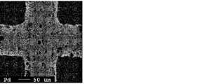
- FIG. 3 is an EPMA image of the second support layer constituting the honeycomb catalyst according to the first embodiment.
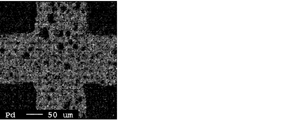
- FIG. 4 is an EPMA image of the second support layer constituting the honeycomb catalyst according to Comparative Example 1.
- a noble metal is supported on a honeycomb structure in which a plurality of through holes are arranged in parallel in the longitudinal direction with a partition wall being separated.
- the honeycomb structure contains ceria-zirconia composite oxide (hereinafter also referred to as CZ) and alumina.
- CZ ceria-zirconia composite oxide
- alumina alumina
- FIG. 1 is a perspective view schematically showing an example of the honeycomb catalyst of the present invention.
- the honeycomb catalyst 10 shown in FIG. 1 includes a single honeycomb structure 11 in which a plurality of through holes 12 are arranged in parallel in the longitudinal direction across the partition walls 13.
- the honeycomb structure 11 contains CZ and alumina, and carries a noble metal.
- the partition walls are disposed on the surface of the partition walls, and the first support layer on which rhodium (Rh) is supported and the inside of the partition walls relative to the first support layer are supported palladium (Pd) is supported And the concentration of Pd on the side of the first support layer of the second support layer is higher than the concentration of Pd at the center of the second support layer (the support region of Pd in the second support layer is the first support layer). It is said that it is biased to the layer side).
- the catalytic activity of Pd is sufficiently exhibited even if the exhaust gas does not reach the deep portion of the second support layer.
- the exhaust gas purification performance can be improved.
- FIG. 2 is a cross-sectional view schematically showing an example of partition walls constituting the honeycomb catalyst of the present invention.
- the partition wall 13 has a first support layer 13a disposed on the surface (the through hole 12 side) of the partition wall 13 and a thickness direction of the partition wall 13 than the first support layer 13a (both in FIG. It consists of the 2nd support layer 13b arrange
- the first support layer 13a supports rhodium 14a, which is a noble metal
- the second support layer 13b supports palladium 14b, which is a noble metal.
- palladium 14b is segregated and supported on the first support layer 13a side, and the Pd concentration on the first support layer side of the second support layer 13b is at the center of the second support layer 13b. It is higher than Pd concentration.
- the fact that the Pd concentration on the first support layer side of the second support layer is higher than the Pd concentration at the center of the second support layer means that the partition walls are cut in the direction perpendicular to the longitudinal direction of the honeycomb catalyst.
- the cut surface can be confirmed by elemental mapping using EPMA or the like. Specifically, first, from the second carrier layer portion of the elemental mapping image of the partition wall, a 10 ⁇ m ⁇ 10 ⁇ m region at the center (the center in the thickness direction) of the second carrier layer and from the region to the first carrier layer side A combination of 10 ⁇ m ⁇ 10 ⁇ m area on the surface of the second support layer located is randomly selected at 10 points.
- the Pd concentration in the 10 ⁇ m ⁇ 10 ⁇ m region at the center of the second support layer is compared with the Pd concentration in the 10 ⁇ m ⁇ 10 ⁇ m region on the surface of the second support layer.
- the concentration of the noble metal can be determined by the hue and density of the elemental mapping image.
- the honeycomb structure constituting the honeycomb catalyst of the present invention may be constituted by a single honeycomb fired body, or may be constituted by a plurality of honeycomb fired bodies, and the plurality of honeycomb fired bodies is an adhesive. You may be comprised by being couple
- the honeycomb fired body is produced by extruding a raw material paste containing ceria-zirconia mixed oxide particles (hereinafter, also referred to as CZ particles) and alumina particles, and firing it.
- the second support layer is constituted by supporting Pd on a honeycomb fired body formed by firing an extrusion-formed body containing ceria-zirconia mixed oxide particles and alumina particles. desirable.
- a coat layer may be formed on the surfaces of the partition walls constituting the honeycomb fired body.
- the first support layer can be formed by forming the coating layer containing Rh.
- the first support layer is preferably a coated layer containing ceria-zirconia mixed oxide, alumina and Rh.
- the average particle diameter of the CZ particles constituting the honeycomb catalyst of the present invention is preferably 1 to 50 ⁇ m from the viewpoint of improving the thermal shock resistance.
- the average particle size of the CZ particles is more preferably 1 to 30 ⁇ m.
- the surface area is increased when the honeycomb catalyst is formed, so that the OSC can be increased.
- the average particle diameter of the alumina particles constituting the honeycomb catalyst of the present invention is not particularly limited, but is preferably 1 to 10 ⁇ m, and more preferably 1 to 5 ⁇ m from the viewpoint of improving the exhaust gas purification performance.
- the average particle diameter of the CZ particles and alumina particles constituting the honeycomb catalyst can be determined by taking a SEM photograph of the honeycomb catalyst using a scanning electron microscope (SEM, S-4800 manufactured by Hitachi High-Tech Co., Ltd.).
- the proportion of the ceria-zirconia composite oxide in the honeycomb catalyst is desirably 25 to 75% by weight.
- the OSC of the honeycomb catalyst can be increased.
- the ratio of the alumina particles in the honeycomb catalyst is desirably 15 to 35% by weight.
- ceria has OSC in the ceria-zirconia mixed oxide that constitutes CZ particles.
- ceria-zirconia mixed oxide it is desirable that ceria and zirconia form a solid solution.
- the ceria-zirconia mixed oxide desirably contains 30 wt% or more of ceria, more desirably 40 wt% or more, and desirably 90 wt% or less of ceria. It is more desirable to contain by weight or less.
- the ceria-zirconia composite oxide desirably contains 60 wt% or less of zirconia, and more desirably 50 wt% or less.
- Such ceria-zirconia mixed oxide has a high ceria ratio, so the OSC is high.
- the type of alumina particles is not particularly limited, but it is desirable that the alumina particles are ⁇ -phase alumina particles (hereinafter also referred to as ⁇ -alumina particles).
- ⁇ -alumina particles ⁇ -phase alumina particles
- alumina particles of the ⁇ phase as a partition material of the ceria-zirconia composite oxide, it is possible to suppress the sintering of the alumina particles with each other during use, so that the catalytic function can be maintained.
- heat resistance can be enhanced by making alumina particles into the ⁇ phase.
- the honeycomb catalyst of the present invention preferably contains inorganic particles used as an inorganic binder at the time of production, and more preferably contains ⁇ -alumina particles derived from boehmite.
- the honeycomb catalyst of the present invention desirably contains inorganic fibers, and more desirably contains alumina fibers.
- the honeycomb catalyst contains inorganic fibers such as alumina fibers, the mechanical properties of the honeycomb catalyst can be improved.
- an inorganic fiber means that whose aspect ratio is 5 or more
- an inorganic particle means that whose aspect ratio is less than 5.
- the ratio of length to diameter (length / diameter) of the honeycomb catalyst is desirably 0.5 to 1.1, and more desirably 0.6 to 0.8. .
- the diameter of the honeycomb catalyst is desirably 130 mm or less, and more desirably 125 mm or less.
- the diameter of the honeycomb catalyst is preferably 85 mm or more.
- the length of the honeycomb catalyst is desirably 65 to 120 mm, and more desirably 70 to 110 mm.
- the shape of the honeycomb catalyst of the present invention is not limited to a cylindrical shape, and may include a prismatic shape, an elliptic cylindrical shape, a long cylindrical shape, and a prismatic columnar shape which is chamfered (for example, a triangular prismatic shape which is chamfered).
- the thickness of the partition walls is desirably uniform. Specifically, the thickness of the partition walls of the honeycomb catalyst is desirably 0.10 to 0.25 mm, and more desirably 0.10 to 0.15 mm.
- the thickness of the first support layer is desirably 0.01 to 0.10 mm on one side, and more desirably 0.02 to 0.05 mm.
- the thickness of the second support layer is desirably 0.05 to 0.20 mm, and more desirably 0.05 to 0.15 mm.
- the shape of the through holes in the honeycomb catalyst of the present invention is not limited to a square pole, and may be a triangular pole, a hexagonal pole, or the like.
- the density of the through holes in the cross section perpendicular to the longitudinal direction of the honeycomb catalyst is 31 to 155 / cm 2 .
- the porosity of the honeycomb catalyst of the present invention is desirably 40 to 70%.
- the porosity of the honeycomb catalyst can be measured by the weight method described below.
- the honeycomb catalyst is cut into a size of 10 cells ⁇ 10 cells ⁇ 10 mm to obtain a measurement sample.
- the measurement sample is subjected to ultrasonic cleaning with ion-exchanged water and acetone, and then dried at 100 ° C. using an oven.
- the measurement sample of 10 cells ⁇ 10 cells ⁇ 10 mm includes the outermost through holes and the partition walls constituting the through holes in a state in which ten through holes are arranged in the longitudinal direction and ten in the lateral direction. It refers to a sample cut out so that the length in the longitudinal direction is 10 mm.
- the true density is measured in accordance with JIS R 1620 (1995) using an Auto Pycnometer 1320 manufactured by Micromeritics.
- the evacuation time is 40 minutes.
- the actual weight of the measurement sample is measured with an electronic balance (HR 202i manufactured by A & D).
- an outer peripheral coat layer may be formed on the outer peripheral surface of the honeycomb fired body.
- the thickness of the outer peripheral coat layer is preferably 0.1 to 2.0 mm.
- a noble metal is supported on the honeycomb structure.
- the noble metal includes Rh supported on the first support layer and Pd supported on the second support layer.
- the loading amount of the noble metal is desirably 0.1 to 15 g / L in total, and more desirably 0.5 to 10 g / L in total.
- the supported amount of the noble metal refers to the weight of the noble metal per apparent volume of the honeycomb catalyst.
- the apparent volume of the honeycomb catalyst is a volume including the volume of the void, and includes the volume of the outer peripheral coat layer and / or the adhesive layer.
- a method for producing a honeycomb fired body for example, a raw material paste containing CZ particles and alumina particles is formed to produce a honeycomb formed body in which a plurality of through holes are arranged in parallel in the longitudinal direction across partition walls.
- a method including a forming step and a firing step of producing a honeycomb fired body by firing the honeycomb formed body.
- the average particle diameter of the CZ particles and the alumina particles which are raw materials of the honeycomb catalyst, can be determined by a laser diffraction type particle size distribution measuring device (MASTER SIZER 2000 manufactured by MALVERN).
- an inorganic fiber As another raw material used when preparing a raw material paste, an inorganic fiber, an inorganic binder, an organic binder, a pore making agent, a shaping
- alumina a silica, a silicon carbide, a silica alumina, glass, a potassium titanate, aluminum borate etc.
- the aspect ratio of the inorganic fiber is preferably 5 to 300, more preferably 10 to 200, and still more preferably 10 to 100.
- the inorganic binder is not particularly limited, and examples thereof include solids contained in alumina sol, silica sol, titania sol, water glass, sepiolite, attapulgite, boehmite and the like. These inorganic binders may be used in combination of two or more.
- Boehmite is desirable.
- Boehmite is an alumina monohydrate represented by the composition of AlOOH, and is well dispersed in a medium such as water, so it is desirable to use boehmite as an inorganic binder.
- the organic binder is not particularly limited, and examples thereof include methyl cellulose, carboxymethyl cellulose, hydroxyethyl cellulose, polyethylene glycol, phenol resin, epoxy resin and the like, and two or more kinds may be used in combination.
- the pore forming agent is not particularly limited, and examples thereof include acrylic resin, coke, starch and the like, and in the present invention, it is desirable to use two or more of acrylic resin, coke and starch.
- the pore forming agent refers to one used for introducing pores into the inside of the honeycomb fired body when the honeycomb fired body is manufactured.
- the shaping aid is not particularly limited, and ethylene glycol, dextrin, fatty acid, fatty acid soap, polyalcohol and the like can be mentioned, and two or more kinds may be used in combination.
- the dispersion medium is not particularly limited, and examples thereof include water, organic solvents such as benzene, alcohols such as methanol, and the like, and two or more types may be used in combination.
- the blending ratio thereof is 25 to 75% by weight of CZ particles with respect to the total solid content remaining after the firing step in the raw materials, alumina particles 15 to 35% by weight, alumina fiber: 5 to 15% by weight and boehmite: 5 to 20% by weight are desirable.
- the raw material paste is formed to produce a honeycomb formed body in which a plurality of through holes are arranged in parallel in the longitudinal direction across the partition walls.
- a honeycomb molded body is produced by extrusion molding using the above-mentioned raw material paste. That is, by passing the paste through a mold of a predetermined shape, a continuous body of a honeycomb formed body having through holes of a predetermined shape is formed, and the honeycomb formed body is obtained by cutting into a predetermined length.
- the honeycomb formed body is dried using a dryer such as a microwave dryer, a hot air dryer, a dielectric dryer, a vacuum dryer, a vacuum dryer, a freeze dryer or the like to produce a honeycomb dried body.
- a dryer such as a microwave dryer, a hot air dryer, a dielectric dryer, a vacuum dryer, a vacuum dryer, a freeze dryer or the like to produce a honeycomb dried body.
- honeycomb formed body and the honeycomb dried body before the firing step are collectively referred to as a honeycomb formed body.
- the honeycomb formed body is fired to produce a honeycomb fired body.
- degreasing and firing of the honeycomb formed body are performed in this step, it may be referred to as “defatting and firing step” but for convenience, it is referred to as “firing step”.
- the temperature of the firing step is preferably 800 to 1300 ° C., and more preferably 900 to 1200 ° C.
- the time of the firing step is preferably 1 to 24 hours, and more preferably 3 to 18 hours.
- the atmosphere in the firing step is not particularly limited, but it is desirable that the oxygen concentration be 1 to 20%.
- a honeycomb fired body can be manufactured by the above steps. Subsequently, a supporting step of supporting Pd on the surfaces of the partition walls of the honeycomb fired body will be described.
- a solution containing a Pd complex As a Pd-containing solution which is easily adsorbed to the partition wall surface of the honeycomb fired body, a solution containing a Pd complex can be mentioned, and as a Pd complex, dinitrodiammine palladium ([Pd (NH 3 ) 2 (NO 2 ) 2 ]), tetraammine palladium dichloride ([Pd (NH 3 ) 4 ] Cl 2 ) and the like can be mentioned. These complexes can be used as a nitric acid solution or an aqueous solution. At this time, by adjusting the pH of the solution to 1.5 to 5.0, the adsorption of Pd on the partition wall surface is more likely to occur. The pH of the above solution can be adjusted by adding a pH adjuster.
- the pH adjuster does not contain halogen and sulfur such as fluorine, chlorine, and bromine which become catalyst poisons, and examples thereof include nitric acid and oxalic acid.
- a slurry for forming a coat layer which is a raw material of the coat layer, is prepared.
- the coat layer forming slurry is obtained by mixing CZ particles, alumina particles and Rh-containing substances with a solvent.
- the Rh-containing substance may be a dispersion solution of Rh particles, or a solution of Rh complex or Rh salt.
- the mixing order of various raw materials is not particularly limited, and CZ particles, alumina particles, Rh-containing substances and a solvent may be mixed at one time.
- CZ particles and Rh-containing substances are mixed to obtain Rh-supported CZ particles
- the Rh-supported CZ particles, the alumina particles and the solvent are then mixed, or the alumina particles and the Rh-containing substance are first mixed to obtain Rh-supported alumina particles, and then the Rh-supported alumina particles, the CZ particles and the solvent are obtained. May be mixed.
- An inorganic binder, a dispersion medium, etc. are mentioned as another raw material used when preparing the slurry for coat layer formation.
- said raw material the thing similar to what is used for the raw material paste at the time of producing a honeycomb molded object can be used suitably.
- the honeycomb fired body having Pd supported on the surface of the partition walls is immersed in the slurry for forming a coat layer, pulled up, dried and fired to form Rh on the surface of the partition walls constituting the honeycomb fired body having Pd supported thereon.
- the present invention provides a honeycomb catalyst of the present invention in which a coating layer containing the above is formed.
- the loading amount of the noble metal loaded in the coating layer forming step is preferably adjusted to a total of 0.1 to 15 g / L, and more preferably a total of 0.5 to 10 g / L.
- the outer peripheral coat layer may be formed by applying the outer peripheral coat layer paste to the outer peripheral surface excluding both end surfaces of the honeycomb fired body and then drying and solidifying it. it can.
- the peripheral coating layer paste include those having the same composition as the raw material paste. However, it is desirable to carry out the step of forming the outer peripheral coat layer after the coat layer forming step.
- an adhesive layer paste is applied to and bonded to the outer peripheral surface excluding the both end surfaces of the plurality of honeycomb fired bodies. After that, those manufactured by drying and solidifying can be used.
- the adhesive layer paste include those having the same composition as the raw material paste.
- Example 1 26.4 wt% of CZ particles [average particle diameter: 2 ⁇ m], 13.2 wt% of ⁇ -alumina particles (average particle diameter: 2 ⁇ m), alumina fibers (average fiber diameter: 3 ⁇ m, average fiber length: 60 ⁇ m) 5.3% by weight, 11.3% by weight of boehmite as an inorganic binder, 5.3% by weight of methylcellulose as an organic binder, 2.1% by weight of an acrylic resin as a pore forming agent, and coke as a pore forming agent 2.
- a raw material paste was prepared by mixing and kneading 6% by weight, 4.2% by weight of polyoxyethylene oleyl ether which is a surfactant as a forming aid, and 29.6% by weight of ion exchanged water.
- the raw material paste was extrusion molded using an extrusion molding machine to produce a cylindrical honeycomb molded body. Then, the honeycomb molded body was dried at a power of 1.74 kW and a reduced pressure of 6.7 kPa for 12 minutes using a vacuum microwave dryer, and then degreased and fired at 1100 ° C. for 10 hours to produce a honeycomb fired body. .
- the honeycomb fired body had a cylindrical shape with a diameter of 103 mm and a length of 105 mm, the density of through holes was 77.5 pieces / cm 2 (500 cpsi), and the thickness of partition walls was 0.076 mm (3 mil).
- CZ particles [average particle size: 2 ⁇ m] are added to and mixed with a rhodium nitrate solution, and after drying the solvent, calcinated at 500 ° C. for 1 hour, Rh-supporting CZ particles having Rh supported on CZ particles are obtained. Obtained. Subsequently, 100 parts by weight of the Rh-supported CZ particles obtained was mixed with 400 parts by weight of ion exchange water to prepare a slurry for forming a coat layer.
- the Pd-loaded honeycomb fired body was immersed in the coat layer forming slurry. Next, the Pd-loaded honeycomb fired body was taken out of the slurry for forming a coating layer, and the air was blown by a blower to blow away the excess slurry for forming a coating layer attached to the Pd-loaded honeycomb fired body. Thereafter, the honeycomb catalyst was dried at 80 ° C. for a whole day and baked at 500 ° C. for 1 hour to obtain a honeycomb catalyst according to Example 1 in which a coating layer containing a noble metal was formed on the surface of partition walls. The loading amount of Rh was 0.4 g / L per apparent volume of the honeycomb catalyst.
- Comparative example 1 A honeycomb catalyst according to Comparative Example 1 was prepared in the same manner as in Example 1 except that the solution used in (loading step) was changed to a palladium nitrate solution.
- a honeycomb fired body (a honeycomb fired body supporting Pd) used when producing a honeycomb catalyst according to Example 1 and Comparative Example 1 is cut in a direction perpendicular to the longitudinal direction, and a partition wall exposed on a cut surface (that is, The second support layer was observed by EPMA to obtain an elemental mapping image.
- a honeycomb fired body supporting Pd was processed into 3 cells ⁇ 3 cells ⁇ 10 mm, solidified with an epoxy resin and then mirror-polished, and platinum was deposited on the observation surface to obtain an observation sample.
- the equipment used was JEOL's JXA8500F.
- the elemental distribution of Pd was mapped with an acceleration voltage of 25 kV, an irradiation current of 4 ⁇ 10 -8 A, a beam diameter of 10 ⁇ m, and an irradiation time of 40 ms.
- the observation sample of 3 cells ⁇ 3 cells ⁇ 10 mm includes the outermost through holes and the partition walls forming the through holes in a state in which three through holes are arranged in the longitudinal direction and three in the lateral direction. It refers to a sample cut out so that the length in the longitudinal direction is 10 mm.
- FIG. 3 is an EPMA image of the second support layer constituting the honeycomb catalyst according to Example 1
- FIG. 4 is an EPMA image of the second support layer constituting the honeycomb catalyst according to Comparative Example 1. From FIG.
- the Pd concentration on the first support layer side is higher than the Pd concentration at the center (localized on the first support layer side) confirmed.
- FIG. 4 it was confirmed from FIG. 4 that, in the second support layer constituting the honeycomb catalyst according to Comparative Example 1, Pd was supported substantially uniformly in the second support layer.
- the honeycomb catalyst according to Example 1 and Comparative Example 1 is set in a V-type 6-cylinder 3.5 L engine, and HC concentration ((HC inflow-HC outflow) / (HC inflow) from the start of the stoichiometric engine
- HC concentration ((HC inflow-HC outflow) / (HC inflow) from the start of the stoichiometric engine
- the temperature when x 100) reached 50% was measured to evaluate the warm-up performance of the honeycomb catalyst.
- the lower the temperature at which the HC concentration is 50% the better the warm-up performance, and if the temperature is lower than 280 ° C., it is judged that the exhaust gas purification performance is sufficient. .
- Table 1 The results are shown in Table 1.
Landscapes
- Chemical & Material Sciences (AREA)
- Engineering & Computer Science (AREA)
- Chemical Kinetics & Catalysis (AREA)
- Materials Engineering (AREA)
- Organic Chemistry (AREA)
- Ceramic Engineering (AREA)
- Health & Medical Sciences (AREA)
- Environmental & Geological Engineering (AREA)
- Combustion & Propulsion (AREA)
- Biomedical Technology (AREA)
- Analytical Chemistry (AREA)
- General Chemical & Material Sciences (AREA)
- Oil, Petroleum & Natural Gas (AREA)
- Toxicology (AREA)
- Mechanical Engineering (AREA)
- General Engineering & Computer Science (AREA)
- Structural Engineering (AREA)
- Catalysts (AREA)
- Exhaust Gas Treatment By Means Of Catalyst (AREA)
- Exhaust Gas After Treatment (AREA)
Abstract
L'invention concerne un catalyseur en nid d'abeilles qui est constitué par support d'un métal noble sur une structure en nid d'abeilles dans laquelle une pluralité de trous traversant est séparée par des parois de séparation et rangée dans une direction longitudinale. Ce catalyseur en nid d'abeilles est caractéristiques en ce que ladite structure en nid d'abeilles contient un oxyde complexe cérium-zircone et une alumine. Lesdites parois de séparation sont constituées d'une première couche de support disposée à leur surface et supportant un Rh, et d'une seconde couche de support disposée au niveau de leur côté interne par rapport à ladite première couche de support et supportant un Pd, la concentration en Pd côté première couche de support de ladite seconde couche de support, étant supérieure à la concentration en Pd au centre de ladite seconde couche de support.
Priority Applications (3)
| Application Number | Priority Date | Filing Date | Title |
|---|---|---|---|
| EP18860742.8A EP3689455A4 (fr) | 2017-09-27 | 2018-09-27 | Catalyseur en nid d'abeilles |
| CN201880061582.0A CN111107933A (zh) | 2017-09-27 | 2018-09-27 | 蜂窝催化剂 |
| US16/830,275 US20200222889A1 (en) | 2017-09-27 | 2020-03-26 | Honeycomb catalytic converter |
Applications Claiming Priority (2)
| Application Number | Priority Date | Filing Date | Title |
|---|---|---|---|
| JP2017186473A JP6698601B2 (ja) | 2017-09-27 | 2017-09-27 | 排ガス浄化用ハニカム触媒 |
| JP2017-186473 | 2017-09-27 |
Related Child Applications (1)
| Application Number | Title | Priority Date | Filing Date |
|---|---|---|---|
| US16/830,275 Continuation US20200222889A1 (en) | 2017-09-27 | 2020-03-26 | Honeycomb catalytic converter |
Publications (1)
| Publication Number | Publication Date |
|---|---|
| WO2019065799A1 true WO2019065799A1 (fr) | 2019-04-04 |
Family
ID=65901481
Family Applications (1)
| Application Number | Title | Priority Date | Filing Date |
|---|---|---|---|
| PCT/JP2018/035837 Ceased WO2019065799A1 (fr) | 2017-09-27 | 2018-09-27 | Catalyseur en nid d'abeilles |
Country Status (5)
| Country | Link |
|---|---|
| US (1) | US20200222889A1 (fr) |
| EP (1) | EP3689455A4 (fr) |
| JP (1) | JP6698601B2 (fr) |
| CN (1) | CN111107933A (fr) |
| WO (1) | WO2019065799A1 (fr) |
Cited By (2)
| Publication number | Priority date | Publication date | Assignee | Title |
|---|---|---|---|---|
| EP3730203A1 (fr) * | 2019-04-25 | 2020-10-28 | Toyota Jidosha Kabushiki Kaisha | Catalyseur de purification de gaz d'échappement |
| CN113840656A (zh) * | 2019-05-15 | 2021-12-24 | 株式会社科特拉 | 排气净化催化剂装置 |
Families Citing this family (4)
| Publication number | Priority date | Publication date | Assignee | Title |
|---|---|---|---|---|
| JP2019058876A (ja) | 2017-09-27 | 2019-04-18 | イビデン株式会社 | ハニカム触媒 |
| JP6815443B2 (ja) | 2019-06-26 | 2021-01-20 | 株式会社キャタラー | 排ガス浄化触媒装置 |
| WO2022258962A1 (fr) * | 2021-06-10 | 2022-12-15 | Johnson Matthey Public Limited Company | Fixation du palladium et faible capacité de stockage d'oxygène frais au moyen d'acide tanique en tant qu'agent complexant et réducteur |
| CN117177813A (zh) * | 2021-06-10 | 2023-12-05 | 庄信万丰股份有限公司 | 使用铑/铂和鞣酸作为络合和还原剂的改进的twc活性 |
Citations (2)
| Publication number | Priority date | Publication date | Assignee | Title |
|---|---|---|---|---|
| JP2009255032A (ja) * | 2008-03-27 | 2009-11-05 | Ibiden Co Ltd | ハニカム構造体 |
| JP2017039069A (ja) | 2015-08-18 | 2017-02-23 | 株式会社デンソー | 排ガス浄化触媒 |
Family Cites Families (3)
| Publication number | Priority date | Publication date | Assignee | Title |
|---|---|---|---|---|
| WO2009118866A1 (fr) * | 2008-03-27 | 2009-10-01 | イビデン株式会社 | Structure en nid d'abeilles |
| JP5386121B2 (ja) * | 2008-07-25 | 2014-01-15 | エヌ・イーケムキャット株式会社 | 排気ガス浄化触媒装置、並びに排気ガス浄化方法 |
| CN103157470B (zh) * | 2013-03-15 | 2015-11-04 | 无锡威孚环保催化剂有限公司 | 汽车尾气三元催化剂 |
-
2017
- 2017-09-27 JP JP2017186473A patent/JP6698601B2/ja active Active
-
2018
- 2018-09-27 WO PCT/JP2018/035837 patent/WO2019065799A1/fr not_active Ceased
- 2018-09-27 CN CN201880061582.0A patent/CN111107933A/zh active Pending
- 2018-09-27 EP EP18860742.8A patent/EP3689455A4/fr not_active Withdrawn
-
2020
- 2020-03-26 US US16/830,275 patent/US20200222889A1/en not_active Abandoned
Patent Citations (2)
| Publication number | Priority date | Publication date | Assignee | Title |
|---|---|---|---|---|
| JP2009255032A (ja) * | 2008-03-27 | 2009-11-05 | Ibiden Co Ltd | ハニカム構造体 |
| JP2017039069A (ja) | 2015-08-18 | 2017-02-23 | 株式会社デンソー | 排ガス浄化触媒 |
Non-Patent Citations (1)
| Title |
|---|
| See also references of EP3689455A4 |
Cited By (2)
| Publication number | Priority date | Publication date | Assignee | Title |
|---|---|---|---|---|
| EP3730203A1 (fr) * | 2019-04-25 | 2020-10-28 | Toyota Jidosha Kabushiki Kaisha | Catalyseur de purification de gaz d'échappement |
| CN113840656A (zh) * | 2019-05-15 | 2021-12-24 | 株式会社科特拉 | 排气净化催化剂装置 |
Also Published As
| Publication number | Publication date |
|---|---|
| CN111107933A (zh) | 2020-05-05 |
| US20200222889A1 (en) | 2020-07-16 |
| JP2019058872A (ja) | 2019-04-18 |
| EP3689455A1 (fr) | 2020-08-05 |
| JP6698601B2 (ja) | 2020-05-27 |
| EP3689455A4 (fr) | 2021-06-09 |
Similar Documents
| Publication | Publication Date | Title |
|---|---|---|
| JP6998871B2 (ja) | ハニカム構造体及び該ハニカム構造体の製造方法 | |
| JP6698602B2 (ja) | 排ガス浄化用ハニカム触媒 | |
| JP6698601B2 (ja) | 排ガス浄化用ハニカム触媒 | |
| JPWO2018012565A1 (ja) | ハニカム構造体及び該ハニカム構造体の製造方法 | |
| JP6684257B2 (ja) | 排ガス浄化用ハニカム触媒 | |
| WO2019065805A1 (fr) | Catalyseur en nid d'abeilles | |
| WO2019065797A1 (fr) | Catalyseur en nid d'abeilles | |
| JP2020040033A (ja) | ハニカム構造体 | |
| JP6726148B2 (ja) | 排ガス浄化用ハニカム触媒 | |
| JP6949019B2 (ja) | ハニカム構造体及び該ハニカム構造体の製造方法 | |
| JP6782571B2 (ja) | ハニカム構造体 | |
| JP7186031B2 (ja) | ハニカム構造体 | |
| JP2019063683A (ja) | ハニカム触媒の製造方法 | |
| JP6944833B2 (ja) | ハニカム構造体の製造方法 | |
| JP6985854B2 (ja) | ハニカム構造体の製造方法 | |
| JP2019151508A (ja) | ハニカム構造体の製造方法 | |
| WO2019026645A1 (fr) | Procédé de production d'une structure en nid d'abeilles et structure en nid d'abeilles | |
| WO2020105665A1 (fr) | Structure en nid d'abeille | |
| WO2020105666A1 (fr) | Corps à structure en nid d'abeilles | |
| JP2019150754A (ja) | ハニカム構造体の製造方法 |
Legal Events
| Date | Code | Title | Description |
|---|---|---|---|
| 121 | Ep: the epo has been informed by wipo that ep was designated in this application |
Ref document number: 18860742 Country of ref document: EP Kind code of ref document: A1 |
|
| NENP | Non-entry into the national phase |
Ref country code: DE |
|
| ENP | Entry into the national phase |
Ref document number: 2018860742 Country of ref document: EP Effective date: 20200428 |
|
| WWW | Wipo information: withdrawn in national office |
Ref document number: 2018860742 Country of ref document: EP |