WO2019065970A1 - Dispositif de reconnaissance extérieur de véhicule - Google Patents
Dispositif de reconnaissance extérieur de véhicule Download PDFInfo
- Publication number
- WO2019065970A1 WO2019065970A1 PCT/JP2018/036265 JP2018036265W WO2019065970A1 WO 2019065970 A1 WO2019065970 A1 WO 2019065970A1 JP 2018036265 W JP2018036265 W JP 2018036265W WO 2019065970 A1 WO2019065970 A1 WO 2019065970A1
- Authority
- WO
- WIPO (PCT)
- Prior art keywords
- feature point
- vehicle
- obstacle
- road surface
- image
- Prior art date
- Legal status (The legal status is an assumption and is not a legal conclusion. Google has not performed a legal analysis and makes no representation as to the accuracy of the status listed.)
- Ceased
Links
Images







Classifications
-
- G—PHYSICS
- G06—COMPUTING OR CALCULATING; COUNTING
- G06V—IMAGE OR VIDEO RECOGNITION OR UNDERSTANDING
- G06V20/00—Scenes; Scene-specific elements
- G06V20/50—Context or environment of the image
- G06V20/56—Context or environment of the image exterior to a vehicle by using sensors mounted on the vehicle
- G06V20/58—Recognition of moving objects or obstacles, e.g. vehicles or pedestrians; Recognition of traffic objects, e.g. traffic signs, traffic lights or roads
-
- B—PERFORMING OPERATIONS; TRANSPORTING
- B60—VEHICLES IN GENERAL
- B60R—VEHICLES, VEHICLE FITTINGS, OR VEHICLE PARTS, NOT OTHERWISE PROVIDED FOR
- B60R11/00—Arrangements for holding or mounting articles, not otherwise provided for
- B60R11/04—Mounting of cameras operative during drive; Arrangement of controls thereof relative to the vehicle
-
- B—PERFORMING OPERATIONS; TRANSPORTING
- B60—VEHICLES IN GENERAL
- B60R—VEHICLES, VEHICLE FITTINGS, OR VEHICLE PARTS, NOT OTHERWISE PROVIDED FOR
- B60R99/00—Subject matter not provided for in other groups of this subclass
-
- G—PHYSICS
- G01—MEASURING; TESTING
- G01B—MEASURING LENGTH, THICKNESS OR SIMILAR LINEAR DIMENSIONS; MEASURING ANGLES; MEASURING AREAS; MEASURING IRREGULARITIES OF SURFACES OR CONTOURS
- G01B11/00—Measuring arrangements characterised by the use of optical techniques
-
- G—PHYSICS
- G06—COMPUTING OR CALCULATING; COUNTING
- G06T—IMAGE DATA PROCESSING OR GENERATION, IN GENERAL
- G06T7/00—Image analysis
-
- G—PHYSICS
- G06—COMPUTING OR CALCULATING; COUNTING
- G06V—IMAGE OR VIDEO RECOGNITION OR UNDERSTANDING
- G06V10/00—Arrangements for image or video recognition or understanding
- G06V10/40—Extraction of image or video features
- G06V10/44—Local feature extraction by analysis of parts of the pattern, e.g. by detecting edges, contours, loops, corners, strokes or intersections; Connectivity analysis, e.g. of connected components
- G06V10/443—Local feature extraction by analysis of parts of the pattern, e.g. by detecting edges, contours, loops, corners, strokes or intersections; Connectivity analysis, e.g. of connected components by matching or filtering
-
- G—PHYSICS
- G06—COMPUTING OR CALCULATING; COUNTING
- G06V—IMAGE OR VIDEO RECOGNITION OR UNDERSTANDING
- G06V10/00—Arrangements for image or video recognition or understanding
- G06V10/40—Extraction of image or video features
- G06V10/50—Extraction of image or video features by performing operations within image blocks; by using histograms, e.g. histogram of oriented gradients [HoG]; by summing image-intensity values; Projection analysis
- G06V10/507—Summing image-intensity values; Histogram projection analysis
-
- G—PHYSICS
- G06—COMPUTING OR CALCULATING; COUNTING
- G06V—IMAGE OR VIDEO RECOGNITION OR UNDERSTANDING
- G06V20/00—Scenes; Scene-specific elements
- G06V20/60—Type of objects
- G06V20/64—Three-dimensional [3D] objects
-
- G—PHYSICS
- G08—SIGNALLING
- G08G—TRAFFIC CONTROL SYSTEMS
- G08G1/00—Traffic control systems for road vehicles
- G08G1/16—Anti-collision systems
-
- B—PERFORMING OPERATIONS; TRANSPORTING
- B60—VEHICLES IN GENERAL
- B60R—VEHICLES, VEHICLE FITTINGS, OR VEHICLE PARTS, NOT OTHERWISE PROVIDED FOR
- B60R2300/00—Details of viewing arrangements using cameras and displays, specially adapted for use in a vehicle
- B60R2300/10—Details of viewing arrangements using cameras and displays, specially adapted for use in a vehicle characterised by the type of camera system used
- B60R2300/105—Details of viewing arrangements using cameras and displays, specially adapted for use in a vehicle characterised by the type of camera system used using multiple cameras
-
- B—PERFORMING OPERATIONS; TRANSPORTING
- B60—VEHICLES IN GENERAL
- B60R—VEHICLES, VEHICLE FITTINGS, OR VEHICLE PARTS, NOT OTHERWISE PROVIDED FOR
- B60R2300/00—Details of viewing arrangements using cameras and displays, specially adapted for use in a vehicle
- B60R2300/80—Details of viewing arrangements using cameras and displays, specially adapted for use in a vehicle characterised by the intended use of the viewing arrangement
- B60R2300/8093—Details of viewing arrangements using cameras and displays, specially adapted for use in a vehicle characterised by the intended use of the viewing arrangement for obstacle warning
Definitions
- the present invention relates to a vehicle external environment recognition apparatus that recognizes a space around which a vehicle can travel around based on information from an image sensor such as a camera.
- the travelable area around the vehicle After the parking space is detected, if the travelable area around the vehicle can be recognized, it is possible to generate an optimal parking path according to the travelable area, and parking can be performed in the shortest time. On the other hand, if the position of the obstacle around the vehicle can not be detected correctly, a parking path will be generated within the drivable area that is narrower than the actual one, and the phenomenon such as turning back increases or judging that parking can not be made Occurs and the usability of the user is reduced. In order to solve this problem, there is a method of confirming whether the measured obstacle is correct.
- a foot position on an image is calculated from means for detecting a feature point from an image and measuring three-dimensional information from time-series movement of the feature point and the measured feature point.
- a method of using the presence or absence of the edge of to determine that the measurement result of the feature point is not probable when the edge exists is described.
- the present invention has been made in view of the above-described point, and the purpose thereof is the certainty of measurement of feature points even if the obstacle is difficult to observe the edge of the foot using a camera image It is an object of the present invention to provide a vehicle external world recognition device capable of determining
- An on-vehicle external environment recognition apparatus for recognizing a travelable space around the vehicle, and an image acquisition unit for acquiring an image including the environment around the vehicle
- a feature point position measuring unit for extracting feature points from the image and measuring a three-dimensional position of the feature points based on a movement on the image in which the feature points are traced in time series
- a road surface area estimation unit that estimates a road surface area on which the vehicle can travel using similarity
- a feature point foot position calculation unit that calculates a foot position from the three-dimensional position of the feature point, and a foot position of the feature point
- an obstacle determination unit that compares the road surface area with the road surface area and determines that the foot position is a feature point not included in the road surface area as a feature point of a stationary obstacle around the vehicle.
- the foot position of the feature point is different from the position of the edge, or the foot position is different because the certainty of the feature point is determined using the overlap between the foot position of the measured feature point and the road surface area. Even if it is difficult to observe the edge, it is not affected. In addition, there is no occurrence of an erroneous determination due to an edge that is present by chance. Therefore, the position of the stationary obstacle around the vehicle can be accurately grasped.
- FIG. 1 is a block diagram of an in-vehicle external world recognition device according to a first embodiment. The figure explaining the composition of an image acquisition part.
- the flowchart which showed the flow of processing of the feature point position measurement part. Explanatory drawing of a process of a feature point position measurement part.
- the flowchart which showed the flow of processing of a foot position calculation part. Explanatory drawing of a process of a foot position calculation part.
- the flowchart which showed the flow of processing of an obstacle judging part. The flowchart which showed the flow of a different process of an obstruction determination part.
- the block diagram which shows the structure of the vehicle-mounted external world recognition apparatus in 2nd embodiment.
- the flowchart which showed the flow of processing of the obstacle direction calculation part.
- the flowchart which showed the flow of processing of an obstacle judging part.
- the flowchart which showed the flow of processing of an obstacle judging part.
- the figure explaining an example of the obstruction determination by the obstruction determination part The figure explaining an example of the obstruction determination by the obstruction determination part.
- FIG. 1 is a block diagram of an on-vehicle external environment recognition apparatus 1000 according to the first embodiment.
- the on-vehicle external environment recognition apparatus 1000 is incorporated in a camera apparatus mounted in a car, or in an integrated controller, etc., and is for recognizing the external world from images captured by the cameras 1001 to 1004 of the camera apparatus. In the embodiment, it is configured to recognize an obstacle around the vehicle.
- the on-vehicle external environment recognition apparatus 1000 is configured by a computer having a CPU, a memory, an I / O, and the like, and a predetermined process is programmed to repeatedly execute the process in a predetermined cycle T.
- the on-vehicle external environment recognition apparatus 1000 includes an image acquisition unit 1011, a feature point position measurement unit 1021, a feature point foot position calculation unit 1031, a road surface area estimation unit 1041, and an obstacle determination unit 1051. Have.
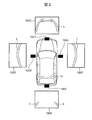
- the image acquisition unit 1011 acquires an image including the environment around the vehicle. As shown in FIG. 2, the image acquisition unit 1011 is one or more of the images 1005 to 1008 obtained by photographing the surroundings of the vehicle from the cameras 1001 to 1004 attached at positions where the surroundings of the vehicle 10 can be imaged. To get In the present embodiment, based on the information on the traveling direction of the vehicle 10, an image 1005 captured by the front camera 1001 is acquired during forward movement, and an image 1008 captured by the rear camera 1004 is acquired during reverse travel. The acquired images are recorded on the RAM as a two-dimensional array. Hereinafter, the input image is represented by IMGSRC [x] [y]. x and y indicate coordinates of the image, respectively. Each of the images 1005 to 1008 shown in FIG. 2 is an image when the vehicle 10 is parked forward in the parking frame, and the dividing line L of the parking space is captured.
- the feature point position measurement unit 1021 extracts feature points from the image, and measures the three-dimensional position of the feature points based on the movement on the image in which the feature points are tracked in time series. That is, the feature point position measurement unit 1021 extracts the feature point FP [p] from the input image IMGSRC [x] [y], and moves on the image in which the feature point FP [p] is traced in time series (feature point Based on the time-series change, the distance from the vehicle 10 to the feature point FP [p] is measured as the three-dimensional position of the feature point.
- the feature point position measurement unit 1021 detects feature points FP [p] from the input image IMGSRC [x] [y] and tracks them in time series to obtain a three-dimensional distance from the image coordinate table FPI [p] of each feature point. Measure the table FPW [p].
- FPI [p] is an image coordinate (x, y)
- FPW [p] is a one-dimensional array of a table having elements of world coordinates (x, y, z) whose origin is the rear wheel axle of the vehicle.
- P represents an ID when a plurality of detected. Details of the process will be described later.
- the feature point and foot position calculation unit 1031 calculates the foot position of the feature point from the three-dimensional position of the feature point. That is, the feature point foot position calculation unit 1031 uses the camera geometric information such as the camera installation height and angle from the world coordinates FPW [p] of the feature point FP [p] to the foot position FPW0 [of the feature point FP [p]. p] is calculated.
- FPW 0 [p] is a one-dimensional array of a table having an element of world coordinates (x, y, 0), and p represents an ID in the case of detecting a plurality of elements. Details of the process will be described later.
- the foot position of the feature point refers to the position on the road surface lowered in the vertical direction from the position of the feature point.
- the road surface area estimation unit 1041 estimates a road surface area on which the vehicle can travel using the similarity of the texture of the image from the image. That is, the road surface area estimation unit 1041 analyzes the texture information of the image from the input image IMGSRC [x] [y] to extract the road surface area.
- IMGSRC [x] [y] There are various ways of holding information, but in the present embodiment, a grid map GRD [x] [y] having an origin of the rear wheel axle of one vehicle is prepared in a range of about 10 m in front and rear, around 5 cm in 1 grid, It is assumed that the road surface area has an estimated value of “1”, and the non-road surface area has an estimated value of “0”. Details of the process will be described later.
- FIG. 3 is a flowchart showing the process flow of the feature point position measurement unit 1021.
- FIG. 4 is an explanatory diagram of processing of the feature point position measurement unit 1021.
- the feature point position measurement unit 1021 executes the input image IMGSRC [x] [y].
- step S301 the feature point FPI [p] is extracted from the input image IMGSRC [x] [y] that is the current image. Extraction of feature point FPI [p] uses a known method such as Harris corner. As a result, image coordinates are obtained for each feature point.
- step S302 a past image IMGSRC_P before a predetermined time acquired from the same camera is acquired.
- step S303 an optical flow is calculated from the current image and the past image.
- the corresponding position on the past image IMGSRC_P of each feature point FPI [p] on the current image IMGSRC is calculated by the optical flow method, and the movement vectors FP_VX [p] and FP_VY [p] of each feature point are acquired.
- the optical flow uses known methods such as the Lucas-Kanade method.
- step S304 three-dimensional information FPW [p] is calculated from the optical flow.
- the three-dimensional position of each feature point FPI [p] around the vehicle is calculated using the feature point FPI [p] and the movement vectors FP_VX [p] and FP_VY [p].
- the calculation method uses a known means.
- the movement vector on the image and the movement amount of the vehicle calculated using the vehicle positions DRC [t] and DRC [t-1] acquired by CAN are used.
- t is a symbol representing processing timing
- the own vehicle movement amount DRC [t] is an X, Y, and yaw angle in a coordinate system having the center of the rear wheel axle of the own vehicle as the origin. From the own vehicle positions DRC [t] and DRC [t-1], movement amounts of X, Y, and yaw angle can be obtained.
- step S305 processing is performed to acquire relative coordinates of each feature point.
- the three-dimensional position of each feature point is converted into a coordinate system having the center of the rear wheel axle of the vehicle as an origin, and stored as a distance table FPW [p].
- a parallax is generated by changing the past vehicle position DRC [t-1] and the current vehicle position DRC [t], and the distance can be measured.
- the distance Y to the parked vehicle 20 is measured based on the parallax generated as the vehicle 10 travels by the distance d from time t-1 to time t.
- the measurement result of the parked vehicle 20 is measured as a plurality of points 21 as shown in FIG. 4 (b).
- the road surface height is set to a position higher than the actual road surface to calculate the image coordinates.
- a method of calculating three-dimensional coordinates at a road surface height position of image coordinates This second method will be described with reference to FIG.
- FIG. 5 is a flowchart showing the process flow of the foot position calculation unit 1031.
- step S502 the height z of the distance table FPW0T [p] is set to a value "Hv" higher than the actual road surface.
- step S503 the image coordinate table FPI0 [p] is calculated from the distance table FPW0T [p].
- camera geometric information such as the installation height of the camera registered in advance, the installation angle, and the distortion table of the lens are used.
- a process of calculating image coordinates from world coordinates using camera geometric information is a known technique, and therefore detailed description will be omitted.
- FIG. 6 is a view schematically showing a situation in which another camera is imaged by the camera of the own vehicle, and FIG. 6 (a) shows the first method, and FIG. 6 (b) shows the second method Is shown.
- the foot position calculated by the feature point foot position calculation unit 1031 is embedded in the road surface area estimated by the road surface area estimation unit 104.
- the object determination unit 1051 may determine that the feature point is erroneously detected and may be removed.
- the second method as shown in FIG. 6 (b)
- the obstacle judging unit 1051 if a position obtained by extending the line connecting the camera and the foot position to the position of height HV from the foot surface to the road surface is near the edge of the estimated road surface area, Perform processing to leave as feature points of obstacles.
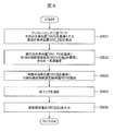
- FIG. 7 is a flowchart showing the process flow of the road surface area estimation unit 1041.
- the road surface area estimation unit 1041 performs the input image IMGSRC [x] [y]. There are various methods of estimating the road surface area from the image, for example, a method using machine learning, a method using the similarity in the image, etc. In this embodiment, the method is implemented using the result of the feature point position measurement unit 1021 Method is used.
- step S701 the input image IMGSRC [x] [y] is divided into a plurality of local regions R [r].
- the table rd [d] of the ID of the local region R [r] to which the feature point belongs is extracted.
- step S703 histogram information Hst1 of an image is acquired from a local region R [rd [d]] to which a feature point within the range of road surface heights belongs.
- step S704 the processing in steps S704 and S705 is performed on the local region R [r '] in the vicinity of the local region R [rd [d]] to which the feature point in the range of road surface heights belongs.
- the determination of the vicinity is, for example, a region in which the distance between the centers of the local region R [rd [d]] and the local region R [r '] is equal to or less than the threshold thRDist.
- step S704 histogram information Hst2 of the local region R [r '] is acquired.
- step S706 When the process is completed for all rd [d], the process moves to step S706, and all local areas R [rd [d]], R [rdm [dm]] belonging to rd [d] and rdm [dm] are processed. Is extracted as a road surface area estimated instantaneous value RDI [t] in the image.
- step S 707 the boundary of the road surface area is converted into the road surface estimated instantaneous value RDT [x] [y] of the world coordinates using camera geometric information, and time series processing is performed.
- FIG. 8 is a flow of processing
- FIG. 9 is an explanatory view of time series processing.
- step S801 based on the dead reckoning information, the current vehicle position DRC [t] and the previous vehicle position DRC [t-1] are acquired, and the current vehicle position DRC [t] is used as a reference.
- the previous vehicle position DRC_P [t] to be calculated is calculated.
- FIG. 9A is an example thereof. In FIG. 9A, the current vehicle position is indicated by a solid line, and the previous vehicle position is indicated by a broken line.
- step S802 based on the previous vehicle position DRC_P [t], the previous road surface area estimation result GRDz1 [x] [y] is expanded, and a constant value is subtracted from the whole.
- FIG. 9 (b) is an example thereof.
- the previous road surface area estimation result 151 is indicated by a broken line.
- step S803 the road surface area estimated instantaneous value RDT [t] [x] [y] is developed on the basis of the current vehicle position DRC [t].
- FIG. 9C shows an example.
- the current road surface area estimated instantaneous value 152 is indicated by a solid line.
- step S804 the previous road surface area estimation result RDT [t-1] [x] [y] and the current road surface area estimated instantaneous value RDT [t] [x] [y] are added.
- FIG. 9 (d) is an example thereof.
- the overlapping area 153 of the previous and current road surface area estimation instantaneous values is indicated by hatching.
- step S805 the overlapping area is output as the road surface area estimation result GRD [x] [y] of this time, and at the same time, the current road surface area estimation result is output to the previous road surface area estimation result GRDz1 [x] [y]. make a copy.
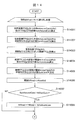
- FIG. 10 is a flowchart showing the process flow of the obstacle judging unit 1051.
- step S1000 foot coordinates FPW0 [p] of the feature point FP [p] are acquired.
- step S10002 the foot coordinates FPW0 [p] are projected onto the road surface area estimation result GRD [x] [y] in step S10002, and the foot coordinates are confirmed, and the road surface area estimated value of the foot coordinates FPW0 [p] is less than the threshold thRoad That is, if it is not a road surface, the process moves to step S10003 and is registered to the obstacle feature point OFP [q].
- FIG. 11 is a flowchart showing a flow of different processing of the obstacle judging unit 1051.
- step S11001 the distance between world coordinates FPW [p] of feature point FP [p] and all world coordinates FPW [p '] except p is compared, and the total number of feature points within radius thAround Calculate SumAround.
- the present embodiment only (x, y) of world coordinates (x, y, z) is used for distance calculation.
- step S11002 the total number SumAround and the threshold thSumFew are compared, and if the total number SumAround is small, the process proceeds to step S11004. If not, the flow goes to step S11005, and the total number SumAround is compared with the threshold thSumMony, and if the total number SumAround is large, the flow goes to step S11005. If not, the process goes to step S11006.
- a threshold thRoad to be used later is set.
- the threshold thRoad thRoadMany.
- step S11007 foot coordinates FPW0 [p] of the feature point FP [p] are acquired.
- step S11008 foot coordinates FPW0 [p] are projected onto road surface area estimation result GRD [x] [y], and foot coordinates are confirmed, and the road surface area estimated value of foot coordinates FPW0 [p] is less than threshold thRoad That is, if it is not a road surface, the process moves to step S10003 and is registered to the obstacle feature point OFP [q].
- Feature point foot position calculation Feature point foot point position calculation As described in the section 1031, the image coordinates are once obtained at a position higher than the road surface height, and it is assumed that the point exists at the road surface height. Even when the target object is floating in the air like a bumper of a vehicle when the installation height of the camera is low, an obstacle can be appropriately determined as an obstacle.
- the feature points are output so as to be isolated like outliers. Can be set easily.
- the feature points are extracted from the image including the environment around the vehicle, and the three-dimensional position of the feature points based on the movement on the image in which the feature points are traced in time series.
- the road surface area on which the vehicle can travel is extracted from the image using the similarity of the texture of the image, and the feature point determined not to be included in the road surface area is highly reliable.
- a process of determining and determining that the reliability is low is performed on the feature point determined to be included in the road surface area at the foot of the feature point.
- a reliable feature point is likely to be a feature point of a stationary obstacle around the vehicle.
- the feature point whose footpoint position of the feature point is included in the road surface area is unlikely to be the feature point of a stationary obstacle around the vehicle, for example, it is expected to be false detection by a moving object . Since the in-vehicle external environment recognition apparatus 1000 determines the likelihood of a feature point using the overlap between the foot position of the measured feature point and the road surface area, the foot position of the feature point is different from the position of the edge, Even if it is difficult to observe the edge of the foot, it is not affected. In addition, there is no occurrence of an erroneous determination due to an edge that is present by chance.
- FIG. 12 is a block diagram showing a configuration of an on-vehicle external world recognition apparatus 2000 in the second embodiment.
- FIG. 12 is a block diagram showing a configuration of an on-vehicle external world recognition apparatus 2000 in the second embodiment.
- What is characteristic in the present embodiment is an obstacle direction calculation unit 2131 having an obstacle information acquisition unit 2111 and a space information acquisition unit 2112 and further using obstacle information obtained from the obstacle information acquisition unit 2111. , And these are input to the obstacle judging unit 2051 which has processing contents different from those in the first embodiment.
- the on-vehicle external world recognition apparatus 2000 is incorporated in a camera apparatus mounted on a car, in an integrated controller, etc., and is for recognizing the external world from the images taken by the cameras 1001 to 1004. So, it is configured to recognize obstacles around the vehicle.
- the on-vehicle external world recognition device 2000 is configured by a computer having a CPU, a memory, an I / O, etc., and a predetermined process is programmed to repeatedly execute the process in a predetermined cycle.
- the image acquisition unit 1011 acquires an image including the environment around the vehicle. As shown in FIG. 2, the image acquisition unit 1011 is one or more of the images 1005 to 1008 obtained by photographing the surroundings of the vehicle from the cameras 1001 to 1004 attached at positions where the surroundings of the vehicle 10 can be imaged. To get In the present embodiment, based on the information on the traveling direction of the vehicle 10, an image 1005 captured by the front camera 1001 is acquired during forward movement, and an image 1008 captured by the rear camera 1004 is acquired during reverse travel. The acquired image is recorded on the RAM as IMGSRC [x] [y]. The description is omitted because it is similar to that of the first embodiment.
- the feature point position measurement unit 1021 detects feature points FP [p] from the input image IMGSRC [x] [y] and tracks them in time series to obtain a three-dimensional distance from the image coordinate table FPI [p] of each feature point. Measure the table FPW [p]. The description is omitted because it is similar to that of the first embodiment.
- the feature point and foot position calculation unit 1031 uses the camera geometric information such as the installation height and angle of the camera from the world coordinates FPW [p] of the feature point FP [p] to determine the foot position FPW0 [p] of the feature point FP [p]. Calculate The description is omitted because it is similar to that of the first embodiment.
- the road surface area estimation unit 1041 analyzes the texture information of the image from the input image IMGSRC [x] [y] and extracts the road surface area. There are various ways of holding information, but in this embodiment, the grid map GRD [x] [y] is used. The description is omitted because it is similar to that of the first embodiment.
- the obstacle information acquisition unit 2111 acquires obstacle information SOBJ [b] acquired from the ultrasonic sensor.
- SOBJ [b] is a one-dimensional array of a table having elements of world coordinates (x, y, z) whose origin is the center of the rear wheel axle of the host vehicle, and b represents an ID when plural detections are made.
- an ultrasonic sensor will be described as an example of a sensor for detecting an obstacle around the host vehicle, but any sensor capable of detecting a sound wave or a light beam may be used.
- Laser radar, LIDAR, and at least one monocular camera may be used.
- the obstacle information acquisition unit 2111 may be anything that can acquire information on an obstacle, and may acquire information transmitted from another vehicle or information transmitted from an infrastructure facility such as a parking lot.
- the space information acquisition unit 2112 acquires information of a space in which the vehicle can travel from the detection results of obstacles around the vehicle detected by the ultrasonic sensor. Specifically, the space information acquisition unit 2112 acquires space information SFS [f] in which the space up to the front of the obstacle detected by the ultrasonic sensor can be confirmed.
- the spatial information SFS [f] is a one-dimensional array of spatial information from each sensor to an obstacle obtained from each ultrasonic sensor, that is, a table representing the travelable distance by a distance, and f is an ultrasonic sensor It is the number of attachment.
- the obstacle direction calculation unit 2131 calculates the directions ⁇ L and ⁇ R of the left and right obstacles of the host vehicle from the obstacle information acquired from the obstacle information acquisition unit 2111. Details of the process will be described later.
- the obstacle determination unit 2051 performs spatial feature calculation to calculate the density of another feature point existing around a predetermined feature point from the three-dimensional position of the feature point, and the height of the feature point density, and the feature The foot position in the image of the point and the road surface area are compared to determine whether the feature point is the feature point of the obstacle. Specifically, the obstacle judging unit 2051 detects the feature point foot position FPW0 [p], the road surface area estimation result GRD [x] [y], the obstacle information SOBJ [b], the space information SFS [f], and the obstacle.
- An obstacle feature point OFP [q] is generated by utilizing information such as the object orientations ⁇ L and ⁇ R. Details of the process will be described later.
- FIG. 13 is a flowchart showing the process flow of the obstacle direction calculation unit 2131.
- There are various methods for calculating the direction of the obstacle but in the present embodiment, side sonar information for accumulating obstacle detection information on the side of the vehicle by the side sonar in time series is accumulated and used in the side sonar table Explain how to do it.
- the side sonar table is assumed to store detection coordinates (x, y) in a coordinate system whose origin is the center of the rear wheel axle of the vehicle, and a time stamp corresponding to dead reckoning.
- step S13001 dead reckoning information is acquired.
- step S13002 the side sonar table processed at the previous time is acquired, and information of the table is moved by the amount of movement from the time of the previous processing to the current calculated by dead reckoning.
- the obstacle information which has left a certain distance from the vehicle is erased.
- obstacle information located behind the rear end 5m of the vehicle is erased.
- step S13003 the side sonar information acquired after the previous processing is registered in the side sonar table.
- step S13004 the least squares method is applied to the obstacle information of each of the vehicle left and right to calculate the obstacle direction ⁇ L from the obstacle on the left side of the vehicle and the obstacle direction ⁇ R from the obstacle on the right side of the vehicle Do.
- the score on the side of the vehicle is equal to or less than the threshold THSSNUM, that is, there is no score for calculating the least squares method, or the straight line calculated by the least squares method and all side sonar obstacle points
- the average SSDIS of the distance with is greater than or equal to the threshold THSSDIS, not the calculated obstacle orientation but the vehicle orientation is adopted.
- FIG. 18 (a) shows an example of a scene in a parking lot having a parking division line, and there is a parking space 1801 for one vehicle on the left side of the vehicle 10, and other vehicles that become obstacles on the left and right It is an example where 1802 is parked.
- FIG. 18B shows the result of time-series accumulation of obstacle detection information on the side of the vehicle by the side sonar in the scene of FIG. 18A.
- the other vehicle 1802 is disposed on the left side of the host vehicle 10, detected by the side sonar, and exists as a plurality of side sonar obstacle points.
- the result of calculating the obstacle direction ⁇ L on the left side of the vehicle by the process of step S13004 is a broken line in FIG. 18 (c).
- the obstacle direction ⁇ R on the right side of the vehicle is the vehicle direction.
- the obstacle determination unit 2051 calculates the density of other feature points existing around a predetermined feature point, and the presence or absence of other feature points on the orientation ⁇ L of the obstacle, and the other on the orientation ⁇ L of the obstacle Based on the result of comparing the presence / absence of the feature point, the feature point density, the foot position of the feature point, and the road surface area, it is determined whether the feature point is the feature point of the obstacle.
- Example 1 of the obstacle determination unit 2051 will be described with reference to FIGS. 14 and 15.
- 14 and 15 are flowcharts showing the flow of processing of the obstacle judging unit 2051.
- This process is performed on all feature points FP [p].
- step S14001 a total number SumAroundCam of the world coordinates FPW [p '] of other feature points within the radius thAroundCam from the world coordinates FPW [p] of the feature point FP [p] is calculated.
- a total number SumAroundCam of the world coordinates FPW [p '] of other feature points within the radius thAroundCam from the world coordinates FPW [p] of the feature point FP [p] is calculated.
- only (x, y) of world coordinates (x, y, z) is used for distance calculation.
- step S14002 the total number SumAroundObj of ultrasonic sensor obstacles SOBJ [b] within the radius thAroundObj from the world coordinates FPW [p] is calculated.
- step S14003 a straight line FPL [p] which is extended in the obstacle azimuth direction from the world coordinates FPW [p] is calculated.
- step S14004 a total number SumLineCam of world coordinates FPW [p '] of other feature points whose vertical distance to the straight line FPL [p] is within the threshold thLineCam is calculated.
- step S14005 the total number SumLineObj of ultrasonic sensor obstacles SOBJ [b] whose vertical distance to the straight line FPL [p] is within the threshold thLineObj is calculated.
- step S14007 SumAroundCam and thSumCam are compared in step S14007, and if larger (SumAroundCam> thSumCam), thAddSumCam is added to the threshold thRoad in step S14008, and the process proceeds to the next. If not (SumAroundCam ⁇ thSumCam), proceed to the next step without doing anything.
- SumAroundObj and thSumObj are compared in step S14009, and if larger (SumAroundObj> thSumObj), thAddSumObj is added to the threshold thRoad in step S14010, and the process proceeds to the next. If not (SumAroundObj ⁇ thSumObj), proceed to the next step without doing anything.
- step S14011 SumLineCam and thSumLineCam are compared in step S14011, and if larger (SumLineCam> thSumLineCam), in step S14012, thAddLineCam is added to the threshold thRoad, and the process proceeds to the next. If not (SumLineCam ⁇ thSumLineCam), proceed to the next step without doing anything.
- SumLineObj and thSumLineObj are compared in step S14013, and if larger (SumLineObj> thSumLineObj), thAddLineObj is added to the threshold thRoad in step S14014, and the process proceeds to the next. If not (SumLineObj ⁇ thSumLineObj), proceed to the next step without doing anything.
- step S14015 it is determined whether or not foot coordinates FPW0 [p] are within sonar space SFS [f]. If within space, thSFS is subtracted from threshold thRoad in step S14016h. If not (if the foot coordinate FPW0 [p] is out of the sonar space SFS [f]), the process advances without doing anything.
- step S14017 it is determined whether the road surface estimated value of the foot coordinate is less than the threshold thRoad using the threshold thRoad adjusted as described above, and if it is less than the threshold, the process proceeds to step S14018 and the obstacle feature amount OFP Register as [q]. If this is not the case (if it is above the threshold value), then proceed without doing anything.
- FIGS. 16 and 17 are flowcharts showing the flow of the process of the obstacle judging unit 2051.
- parts performing the same operations as in FIGS. 14 and 15 are assigned the same reference numerals.
- step S16001 the space information SFS [f] obtained from the ultrasonic sensor is developed on a grid map centered on the rear wheel axle of the host vehicle.
- step S16002 time series processing is performed to obtain a space estimation map GFS [x] [y].
- the flow of time series processing is the same as the flow shown in FIG. 8 and FIG.
- step S14014 the road surface area estimation result GRD [x] [y] at the position of foot coordinates FPW0 [p] is compared with the threshold value thGRD as step S16003, and the road surface area estimation result GRD [x] For [y]> threshold thGRD, thGRD is subtracted from threshold thRoad in step S16004. Otherwise (road surface area estimation result GRD [x] [y] ⁇ threshold thGRD), the process advances to the next without doing anything.
- step S16005 the space estimation map GFS [x] [y] subjected to the time series processing at the position of the foot coordinate FPW0 [p] is referred to, and the value thereof is compared with the threshold thRoad. If it is less than the threshold value, the process advances to step S16006 to register as obstacle feature point OFP [q]. If it is above the threshold, proceed to the next step without doing anything.
- FIG. 19A is an example of a scene in a parking lot having a parking division line, in which there is a parking space 1901 for one car on the left side of the vehicle, and a pedestrian 1903 approaches from the front of the vehicle. . On both sides of the parking space 1901, another vehicle 1902 which is an obstacle is parked.
- FIG. 19B shows detection results by the camera and sonar obtained from the scene of FIG.
- the black points are the detection results by the camera, that is, world coordinates FPW [p] calculated from the feature points FP [p].
- the white point is the detection point by the sonar, that is, the obstacle point SOBJ [b].
- the processing in steps S14001 to S14014 is performed on the world coordinates FPW [p] of the feature point FP [p].
- FIG. 19C is an example of processing for the feature point FP [p1].
- SumAroundCam has a value larger than 0 because world coordinates FPW [p] of another feature point exist in the radius thAroundCam. Since there is no other obstacle point SOBJ [b] in the radius thAroundObj, SumAroundObj is zero. Further, a straight line is drawn from the world coordinates FPW [p1] in the direction of the obstacle direction ⁇ L on the left side of the vehicle, and the number of feature points and the number of obstacles close to the straight line are counted.
- SumLineCam and SumLineObj both have values greater than 0, because the world coordinates of the feature point and the obstacle point are present at close positions of the straight line. Therefore, the threshold thRoad for the feature point FP [p1] has a high value in the processes of steps S14006 to S14014.
- FIG. 19D shows an example of processing for the feature point FP [p2].
- SumAroundCam has a value larger than 0 because world coordinates FPW [p] of another feature point exist in the radius thAroundCam.
- SumAroundObj also has a value greater than zero.
- a straight line is drawn from the world coordinates FPW [p2] in the direction of the obstacle direction ⁇ L on the left side of the vehicle, and the number of feature points and the number of obstacles close to the straight line are counted.
- SumLineCam and SumLineObj have values greater than 0 because the world coordinates of the feature point and the obstacle point are present at close positions of the straight line. Therefore, the threshold thRoad for the feature point FP [p1] has a high value in the processes of steps S14006 to S14014.
- FIG. 19E shows an example of processing for the feature point FP [p3].
- SumAroundCam becomes zero.
- SOBJ [b] in the radius thAroundObj SumAroundObj is also zero.
- a straight line is drawn from the world coordinate FPW [p3] in the direction of the obstacle direction ⁇ L on the left side of the vehicle, and the number of feature points and the number of obstacles close to the straight line are counted.
- the threshold is adjusted according to the presence or absence of another feature point or obstacle point around the world coordinate FPW [p] of the feature point FP [p], and the feature point or obstacle point on the obstacle orientation.
- the threshold for the feature points in FIGS. 19C and 19D is set high, and the feature points are difficult to be removed, while the threshold for the feature points in FIG. 19E is low and is easily removed. Become.
- FIG. 19F feature points that are erroneously detected due to factors such as a moving object can be removed.
- the direction of the obstacle on the side of the vehicle is calculated, and when there is another obstacle on the obstacle direction, the obstacle feature It can be easily adopted as a point. Further, by using the space information obtained from the ultrasonic sensor as a condition for making it difficult to adopt it as an obstacle feature point, it is possible to more easily remove the misdetected feature point. Furthermore, a configuration is also possible in which spatial information obtained from the ultrasonic sensor is used for the final adoption judgment, using the road surface area estimation result as a condition for making it difficult to adopt it as an obstacle feature point.
- FIG. 20 is a diagram for explaining the effect of this embodiment.
- FIG. 20 (a) is a diagram when the result of the process according to the present embodiment is not used.
- the feature point 2011 of the obstacle is erroneously detected.
- An example in which the automatic parking path 2012 is generated so as not to hit an obstacle using the information shown in FIG. 20 (a) is shown in FIG. 20 (b).
- a well-known technique shall be used and description is omitted here.
- FIG. 20C is a diagram in the case of using the result of the process according to the present embodiment.
- FIG. 20 (d) shows an example in which the parking path is similarly generated using the information of the feature points shown in FIG. 20 (c).
- the feature points 2011 that are erroneously detected in FIG. 20A are removed in FIG.
- the automatic parking path 2012 extends because there is a feature point 2011 which is not shown in FIG. 20D. Further, depending on the position of the erroneously detected feature point 2011, the automatic parking path 2012 may not be generated. On the other hand, in FIG. 20 (d), the shortest automatic parking path 2013 can be generated.
Landscapes
- Engineering & Computer Science (AREA)
- Physics & Mathematics (AREA)
- General Physics & Mathematics (AREA)
- Theoretical Computer Science (AREA)
- Multimedia (AREA)
- Computer Vision & Pattern Recognition (AREA)
- Mechanical Engineering (AREA)
- Traffic Control Systems (AREA)
- Image Analysis (AREA)
- Image Processing (AREA)
- Length Measuring Devices By Optical Means (AREA)
Abstract
La présente invention aborde le problème de l'acquisition d'un dispositif de reconnaissance extérieur de véhicule qui est capable d'améliorer la précision d'un procédé de mesure de distance sur la base d'un suivi de point caractéristique d'une image d'appareil de prise de vues. Un dispositif de reconnaissance extérieur embarqué selon la présente invention extrait un point caractéristique d'une image comprenant l'environnement autour d'un véhicule, mesure une position tridimensionnelle du point caractéristique sur la base d'un mouvement dans l'image obtenue par le suivi d'une série chronologique pour le point caractéristique, et calcule une position d'assise sur l'image à partir de la position tridimensionnelle du point caractéristique. Ensuite, le dispositif de reconnaissance extérieur embarqué extrait, à partir de l'intérieur de l'image, une zone de la surface de la route dans laquelle peut se déplacer le véhicule en utilisant une similarité de texture de l'image, et détermine que le point caractéristique, pour lequel la position d'assise du point caractéristique est déterminée comme ne devant pas être incluse dans la zone de surface de route, est hautement fiable.
Priority Applications (2)
| Application Number | Priority Date | Filing Date | Title |
|---|---|---|---|
| EP18861091.9A EP3690802A4 (fr) | 2017-09-29 | 2018-09-28 | Dispositif de reconnaissance extérieur de véhicule |
| US16/651,610 US11514683B2 (en) | 2017-09-29 | 2018-09-28 | Outside recognition apparatus for vehicle |
Applications Claiming Priority (2)
| Application Number | Priority Date | Filing Date | Title |
|---|---|---|---|
| JP2017192230A JP6815963B2 (ja) | 2017-09-29 | 2017-09-29 | 車両用外界認識装置 |
| JP2017-192230 | 2017-09-29 |
Publications (1)
| Publication Number | Publication Date |
|---|---|
| WO2019065970A1 true WO2019065970A1 (fr) | 2019-04-04 |
Family
ID=65902011
Family Applications (1)
| Application Number | Title | Priority Date | Filing Date |
|---|---|---|---|
| PCT/JP2018/036265 Ceased WO2019065970A1 (fr) | 2017-09-29 | 2018-09-28 | Dispositif de reconnaissance extérieur de véhicule |
Country Status (4)
| Country | Link |
|---|---|
| US (1) | US11514683B2 (fr) |
| EP (1) | EP3690802A4 (fr) |
| JP (1) | JP6815963B2 (fr) |
| WO (1) | WO2019065970A1 (fr) |
Cited By (1)
| Publication number | Priority date | Publication date | Assignee | Title |
|---|---|---|---|---|
| CN111563474A (zh) * | 2020-05-18 | 2020-08-21 | 北京茵沃汽车科技有限公司 | 运动背景下的基于车载鱼眼镜头的障碍物检测方法、系统 |
Families Citing this family (9)
| Publication number | Priority date | Publication date | Assignee | Title |
|---|---|---|---|---|
| JP6983309B2 (ja) * | 2018-04-16 | 2021-12-17 | 三菱電機株式会社 | 障害物検出装置、障害物検出装置を利用した自動ブレーキ装置、障害物検出方法、および障害物検出方法を利用した自動ブレーキ方法 |
| JP7179687B2 (ja) * | 2019-06-17 | 2022-11-29 | 株式会社東芝 | 障害物検知装置 |
| JP2022059958A (ja) * | 2020-10-02 | 2022-04-14 | フォルシアクラリオン・エレクトロニクス株式会社 | ナビゲーション装置 |
| US11783597B2 (en) * | 2020-12-30 | 2023-10-10 | Continental Autonomous Mobility US, LLC | Image semantic segmentation for parking space detection |
| CN112801024B (zh) * | 2021-02-09 | 2023-08-29 | 广州小鹏自动驾驶科技有限公司 | 一种检测信息处理方法和装置 |
| JP7561664B2 (ja) * | 2021-03-15 | 2024-10-04 | 株式会社豊田中央研究所 | 物体検出装置、物体検出方法、物体検出プログラム |
| CN114694115B (zh) * | 2022-03-24 | 2025-09-02 | 商汤集团有限公司 | 一种道路障碍物检测方法、装置、设备及存储介质 |
| CN115984799B (zh) * | 2023-02-07 | 2025-08-01 | 曜科智能科技(上海)有限公司 | 一种基于三维先验信息特征融合的车辆重识别方法 |
| JP2024157649A (ja) * | 2023-04-26 | 2024-11-08 | トヨタ自動車株式会社 | 位置推定装置、位置推定システム、位置推定方法、および、コンピュータプログラム |
Citations (3)
| Publication number | Priority date | Publication date | Assignee | Title |
|---|---|---|---|---|
| JP2011150633A (ja) * | 2010-01-25 | 2011-08-04 | Toyota Central R&D Labs Inc | 対象物検出装置及びプログラム |
| JP2014006588A (ja) * | 2012-06-21 | 2014-01-16 | Toyota Central R&D Labs Inc | 路面境界推定装置及びプログラム |
| JP2014240753A (ja) | 2013-06-11 | 2014-12-25 | 富士通株式会社 | 距離測定装置、距離測定方法、およびプログラム |
Family Cites Families (5)
| Publication number | Priority date | Publication date | Assignee | Title |
|---|---|---|---|---|
| WO2006121087A1 (fr) * | 2005-05-10 | 2006-11-16 | Olympus Corporation | Dispositif de traitement d’images, procede de traitement d’images et programme de traitement d’images |
| US20110019873A1 (en) * | 2008-02-04 | 2011-01-27 | Konica Minolta Holdings, Inc. | Periphery monitoring device and periphery monitoring method |
| JP5372680B2 (ja) * | 2009-09-24 | 2013-12-18 | 日立オートモティブシステムズ株式会社 | 障害物検知装置 |
| JP5574789B2 (ja) * | 2010-04-08 | 2014-08-20 | 株式会社東芝 | 車両周辺監視装置及び車両周辺監視方法 |
| US10832061B2 (en) * | 2016-07-22 | 2020-11-10 | Hitachi Automotive Systems, Ltd. | Traveling road boundary estimation apparatus and traveling assistance system using same |
-
2017
- 2017-09-29 JP JP2017192230A patent/JP6815963B2/ja not_active Expired - Fee Related
-
2018
- 2018-09-28 US US16/651,610 patent/US11514683B2/en active Active
- 2018-09-28 EP EP18861091.9A patent/EP3690802A4/fr not_active Withdrawn
- 2018-09-28 WO PCT/JP2018/036265 patent/WO2019065970A1/fr not_active Ceased
Patent Citations (3)
| Publication number | Priority date | Publication date | Assignee | Title |
|---|---|---|---|---|
| JP2011150633A (ja) * | 2010-01-25 | 2011-08-04 | Toyota Central R&D Labs Inc | 対象物検出装置及びプログラム |
| JP2014006588A (ja) * | 2012-06-21 | 2014-01-16 | Toyota Central R&D Labs Inc | 路面境界推定装置及びプログラム |
| JP2014240753A (ja) | 2013-06-11 | 2014-12-25 | 富士通株式会社 | 距離測定装置、距離測定方法、およびプログラム |
Non-Patent Citations (1)
| Title |
|---|
| See also references of EP3690802A4 |
Cited By (1)
| Publication number | Priority date | Publication date | Assignee | Title |
|---|---|---|---|---|
| CN111563474A (zh) * | 2020-05-18 | 2020-08-21 | 北京茵沃汽车科技有限公司 | 运动背景下的基于车载鱼眼镜头的障碍物检测方法、系统 |
Also Published As
| Publication number | Publication date |
|---|---|
| JP2019066333A (ja) | 2019-04-25 |
| US20200302192A1 (en) | 2020-09-24 |
| US11514683B2 (en) | 2022-11-29 |
| EP3690802A1 (fr) | 2020-08-05 |
| JP6815963B2 (ja) | 2021-01-20 |
| EP3690802A4 (fr) | 2021-05-19 |
Similar Documents
| Publication | Publication Date | Title |
|---|---|---|
| JP6815963B2 (ja) | 車両用外界認識装置 | |
| US9846812B2 (en) | Image recognition system for a vehicle and corresponding method | |
| JP6171612B2 (ja) | 仮想レーン生成装置及びプログラム | |
| JP6416293B2 (ja) | 自動車に接近する対象車両を自動車のカメラシステムにより追跡する方法、カメラシステムおよび自動車 | |
| JP6450294B2 (ja) | 物体検出装置、物体検出方法、及びプログラム | |
| CN107209998B (zh) | 车道线识别装置以及车道线识别方法 | |
| CN111937036A (zh) | 用于处理传感器数据的方法、设备和具有指令的计算机可读存储介质 | |
| JP6458651B2 (ja) | 路面標示検出装置及び路面標示検出方法 | |
| US10672141B2 (en) | Device, method, system and computer-readable medium for determining collision target object rejection | |
| JP2004531424A (ja) | 車用の感知装置 | |
| WO2016129403A1 (fr) | Dispositif de détection d'objet | |
| CN105128836A (zh) | 自主紧急制动系统及其中识别行人的方法 | |
| WO2016031494A1 (fr) | Dispositif de détection d'objet | |
| US10970870B2 (en) | Object detection apparatus | |
| CN112455430A (zh) | 无车位线的斜列车位的检测方法、泊车方法及泊车系统 | |
| JP4940177B2 (ja) | 交通流計測装置 | |
| CN110341621B (zh) | 一种障碍物检测方法及装置 | |
| KR102363691B1 (ko) | 자율주행을 위한 객체 속도 추정 장치 및 방법 | |
| JP2019067116A (ja) | 立体物接地判定装置 | |
| CN114084129A (zh) | 一种基于融合的车辆自动驾驶控制方法及系统 | |
| JP2002334330A (ja) | 車両認識装置 | |
| CN105320928A (zh) | 对象物识别装置 | |
| JP4901275B2 (ja) | 走行誘導障害物検出装置および車両用制御装置 | |
| JP7828741B2 (ja) | 画像処理装置 | |
| JP2019148889A (ja) | 道路境界検出装置 |
Legal Events
| Date | Code | Title | Description |
|---|---|---|---|
| 121 | Ep: the epo has been informed by wipo that ep was designated in this application |
Ref document number: 18861091 Country of ref document: EP Kind code of ref document: A1 |
|
| NENP | Non-entry into the national phase |
Ref country code: DE |
|
| ENP | Entry into the national phase |
Ref document number: 2018861091 Country of ref document: EP Effective date: 20200429 |
|
| WWW | Wipo information: withdrawn in national office |
Ref document number: 2018861091 Country of ref document: EP |