WO2019066084A1 - 内視鏡用牽引クリップ - Google Patents
内視鏡用牽引クリップ Download PDFInfo
- Publication number
- WO2019066084A1 WO2019066084A1 PCT/JP2018/036682 JP2018036682W WO2019066084A1 WO 2019066084 A1 WO2019066084 A1 WO 2019066084A1 JP 2018036682 W JP2018036682 W JP 2018036682W WO 2019066084 A1 WO2019066084 A1 WO 2019066084A1
- Authority
- WO
- WIPO (PCT)
- Prior art keywords
- clip
- loop
- sheath
- distal end
- shape
- Prior art date
- Legal status (The legal status is an assumption and is not a legal conclusion. Google has not performed a legal analysis and makes no representation as to the accuracy of the status listed.)
- Ceased
Links
Images











Classifications
-
- A—HUMAN NECESSITIES
- A61—MEDICAL OR VETERINARY SCIENCE; HYGIENE
- A61B—DIAGNOSIS; SURGERY; IDENTIFICATION
- A61B17/00—Surgical instruments, devices or methods
- A61B17/02—Surgical instruments, devices or methods for holding wounds open, e.g. retractors; Tractors
- A61B17/0218—Surgical instruments, devices or methods for holding wounds open, e.g. retractors; Tractors for minimally invasive surgery
-
- A—HUMAN NECESSITIES
- A61—MEDICAL OR VETERINARY SCIENCE; HYGIENE
- A61B—DIAGNOSIS; SURGERY; IDENTIFICATION
- A61B17/00—Surgical instruments, devices or methods
- A61B17/08—Wound clamps or clips, i.e. not or only partly penetrating the tissue ; Devices for bringing together the edges of a wound
- A61B17/083—Clips, e.g. resilient
-
- A—HUMAN NECESSITIES
- A61—MEDICAL OR VETERINARY SCIENCE; HYGIENE
- A61B—DIAGNOSIS; SURGERY; IDENTIFICATION
- A61B17/00—Surgical instruments, devices or methods
- A61B17/10—Surgical instruments, devices or methods for applying or removing wound clamps, e.g. containing only one clamp or staple; Wound clamp magazines
-
- A—HUMAN NECESSITIES
- A61—MEDICAL OR VETERINARY SCIENCE; HYGIENE
- A61B—DIAGNOSIS; SURGERY; IDENTIFICATION
- A61B17/00—Surgical instruments, devices or methods
- A61B17/00234—Surgical instruments, devices or methods for minimally invasive surgery
- A61B2017/00238—Type of minimally invasive operation
- A61B2017/00269—Type of minimally invasive operation endoscopic mucosal resection EMR
-
- A—HUMAN NECESSITIES
- A61—MEDICAL OR VETERINARY SCIENCE; HYGIENE
- A61B—DIAGNOSIS; SURGERY; IDENTIFICATION
- A61B17/00—Surgical instruments, devices or methods
- A61B17/00234—Surgical instruments, devices or methods for minimally invasive surgery
- A61B2017/00292—Surgical instruments, devices or methods for minimally invasive surgery mounted on or guided by flexible, e.g. catheter-like, means
- A61B2017/0034—Surgical instruments, devices or methods for minimally invasive surgery mounted on or guided by flexible, e.g. catheter-like, means adapted to be inserted through a working channel of an endoscope
-
- A—HUMAN NECESSITIES
- A61—MEDICAL OR VETERINARY SCIENCE; HYGIENE
- A61B—DIAGNOSIS; SURGERY; IDENTIFICATION
- A61B17/00—Surgical instruments, devices or methods
- A61B2017/0046—Surgical instruments, devices or methods with a releasable handle; with handle and operating part separable
- A61B2017/00473—Distal part, e.g. tip or head
-
- A—HUMAN NECESSITIES
- A61—MEDICAL OR VETERINARY SCIENCE; HYGIENE
- A61B—DIAGNOSIS; SURGERY; IDENTIFICATION
- A61B90/00—Instruments, implements or accessories specially adapted for surgery or diagnosis and not covered by any of the groups A61B1/00 - A61B50/00, e.g. for luxation treatment or for protecting wound edges
- A61B90/03—Automatic limiting or abutting means, e.g. for safety
- A61B2090/037—Automatic limiting or abutting means, e.g. for safety with a frangible part, e.g. by reduced diameter
Definitions
- the present invention relates to an endoscope pull clip that is used to pull a portion of body tissue by inserting the endoscope into the body.
- ESD endoscopic submucosal dissection
- a procedure may be performed in which a traction force is applied to the lesion in advance, and the entire lesion is incised while lifting the abraded lesion.
- a pulling clip a lifting clip, a clip with a spring
- the lifting clip described in Patent Document 1 is configured to roughly include a clip having a pair of gripping claws (claws), an elastic member made of a cord-like rubber or the like, and an annular member (engaging member). It is done. One end of the elastic member is connected to the base of the clip through a cord-like connecting member, and a ring-shaped member is attached to the other end of the elastic member.
- the separated part of the lesioned part is gripped by the pulling clip, and a pair of claws of another clip (a normal clip not provided with an elastic member, a ring-shaped member, etc.) separately prepared.
- the ring-shaped member is scooped up, and while the elastic member is elastically deformed (stretched), a part of the mucous membrane (for example, a part of mucous membrane facing the lesion) is gripped by the other clip.
- the tractive force acts on the lesioned part by the elastic force (tension) of the elastic member, so that the lesioned part peeled off by the incision is lifted. Therefore, the surgical field can be secured without blocking the view by the exfoliated lesion, and the entire circumference of the lesion can be easily and reliably incised.
- Patent Document 2 describes that a surgical suture can be used as a cord member corresponding to a ring-shaped member.
- cutting of a ring-shaped member is performed by inserting a cutting instrument such as forceps for an endoscope or a high frequency knife, which is also called a loop cutter, through a treatment instrument guide tube of an endoscope.
- a cutting instrument such as forceps for an endoscope or a high frequency knife, which is also called a loop cutter
- the present invention has been made in view of these points, and it is an object of the present invention to provide an endoscope traction clip which can reduce the cost required for treatment without the need to separately prepare a cutting device. Do.
- An endoscope traction clip is A clip body comprising: a pair of arm portions that opens in a substantially V-shape; and a ring-shaped clamping ring slidably fitted on a connection portion on the base end side of the arm portions; A thermoplastic polymer material molded part attached to a part of the clip body directly or through a connecting member, comprising a loop portion formed in a loop shape, wherein a part of the loop portion is more than other portions A loop member having a weak portion that can be cut by a weak force; Have.
- the endoscope traction clip according to the first aspect of the present invention has a fragile portion which can be cut by a force weaker than that of other portions in a portion of the loop portion, so that the loop using the clip device etc.
- the part can be easily cut with a weaker force at the weak part.
- a part of the loop portion can be thinner than another portion to form the fragile portion.
- An endoscope traction clip is A pair of arms that are opened in a substantially V-shape toward the distal end side, and a ring shape slidably fitted on a connection portion on the proximal end side of the arms, the sheath and the sheath
- a clip device having an engaging member which is movably disposed and which engages with the connecting portion in a detachable manner, the engaging member is engaged with the connecting portion with the engaging member through the sheath
- a clip body comprising a clamping ring which is pushed and slid at the distal end of the sheath by pulling it back from the distal end of the sheath;
- Thermoplastic polymeric molded part attached to a part of the clip body directly or via a connecting member, wherein the engaging member of the clip device is formed in a loop shape engageable with the part
- a loop portion is configured to be cut by drawing the engagement member from the distal end of the sheath while the engagement member is engaged with a part
- the endoscope traction clip since a part of the loop member can be cut using the clip device, a separate cutting instrument is prepared to cut the loop member. The cost of treatment can be reduced.
- An endoscope traction clip is A pair of arm portions that opens in a substantially V-shape toward the distal end side, and a ring shape slidably fitted on a connection portion on the base end side of the arm portions, the inner sheath and the inner sheath
- the engaging portion is engaged with the connecting portion by using a clip device having an engaging member which is disposed to be retractable relative to and engageably with the connecting portion, and an outer sheath into which the inner sheath is slidably inserted.
- a clip body provided with a clamping ring which is pushed and slid by the distal end of the inner sheath by pulling the engagement member from the distal end of the inner sheath in a state in which the coupling member is engaged.
- Thermoplastic polymeric molded part attached to a part of the clip body directly or via a connecting member, wherein the engaging member of the clip device is formed in a loop shape engageable with the part
- the engaging member is engaged with the connecting portion of the cutting clip having substantially the same configuration as the clip body using the clip device, and the cutting clip is connected to the tip of the inner sheath using the clip device.
- the cutting clip is configured to be cut by pulling the cutting clip from the distal end of the outer sheath while closing the pair of arm portions of the cutting clip and holding a part of the loop portion.
- a part of the loop member can be cut using the clip device in which the cutting clips are connected. It is not necessary to separately prepare a cutting device, and the cost for treatment can be reduced. In addition, since the cutting clip can be easily replaced after cutting, a new cutting clip can be used each time the cutting operation is repeated using the same clip device.
- the engagement member is spread out in a substantially V shape by being pushed out from the distal end of the sheath, It is possible to use one having a connecting hook that is closed by being drawn into the sheath (or into the inner sheath).
- the loop member can be engaged with the connection hook by closing the connection hook and holding the loop member, so that the operation (work) for engagement becomes easy. , The loop member can be easily cut.
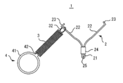
- FIG. 1A is a view showing an entire configuration in a state in which an arm portion of a clip body of an endoscope traction clip according to an embodiment of the present invention is opened.
- FIG. 1B is a view showing the orientation of the clip body constituting the pull clip of FIG. 1A.
- FIG. 1C shows the arm of the clip body of the traction clip of FIG. 1A in a closed position.
- FIG. 2A shows a coil spring of the traction clip of FIG. 1A.
- FIG. 2B is a view of the coil spring of FIG. 2A as viewed from the loop member mounting side.
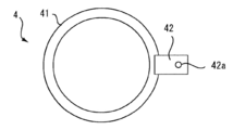
- FIG. 3A is a plan view of the loop member of the traction clip of FIG. 1A.
- FIG. 3B is a front view of the loop member of FIG. 3A.
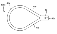
- FIG. 4A is a plan view showing a modification of the loop member of FIG. 3A.
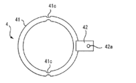
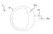
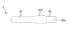
- FIG. 4B is a plan view showing another modified example of the loop member of FIG. 3A.
- FIG. 4C is a plan view showing still another modified example of the loop member of FIG. 3A.
- FIG. 4D is a front view of the loop member of FIG. 4C.
- FIG. 5A is an external view of a clip device according to an embodiment of the present invention.
- FIG. 5B is a cross-sectional view taken along the line Vb-Vb of FIG. 5A.
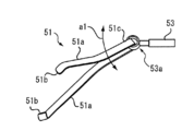
- FIG. 5C is a perspective view showing the connecting hook of the clip device of FIG. 5A and the configuration in the vicinity thereof.
- FIG. 6A shows the tow clip of FIG. 1A protruding from the tip of the clip device.
- FIG. 6B is a view showing a state in which the pulling clip of FIG. 1A is stored at the tip of the clip device.
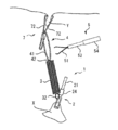
- FIG. 7A is a view schematically showing a state in which a part of a lesion is incised using the traction clip of FIG. 1A.
- FIG. 7B is a view schematically showing a state in which the incision of the lesion in the continuation of FIG. 7A is completed and the tip of the clip device is brought close to cut the loop member.
- FIG. 8A is a view showing a step of cutting a loop member of the traction clip of FIG. 1A, and is a view showing a state in which the tip of the clip device is disposed in the vicinity of the loop member and the connection hook is protruded.
- FIG. 8B is a view showing a process subsequent to FIG. 8A, in which a part of the loop member is gripped by the connection hook, and the connection hook is drawn from the distal end of the sheath to hold the loop member against the distal end of the inner sheath It is a figure which shows the state made to contact.
- FIG. 8C is a view showing a process subsequent to FIG. 8B, in which the connection hook is further drawn in from the end of the inner sheath, and the loop member is cut by the force generated in the loop member by the end of the inner sheath and the connection hook
- FIG. 9A is a plan view showing another modified example of the loop member of FIG. 3A.
- FIG. 9B is a front view of the loop member of FIG. 9A.
- FIG. 9C is a side view of the loop member of FIG. 9A.
- FIG. 9D is a cross-sectional view taken along line IXd-IXd of FIG. 9A.
- FIG. 9E is a cross-sectional view taken along the line IXe-IXe of FIG. 9A.
- FIG. 10A is a view showing another process of cutting the loop member of the pull clip of FIG. 1A, and is a view showing a cutting clip connected to the clip device disposed in the vicinity of the loop member.
- FIG. 10B is a view showing the process continued from FIG. 10A, and showing a state in which the clamp ring is slid and a portion of the loop member is gripped by the cutting clip.
- FIG. 10C is a view showing a process subsequent to FIG.
- the endoscope traction clip 1 is configured to roughly include a clip body 2, a coil spring 3 and a loop member 4.
- the coil spring 3 is an example of a connecting member, and rubber, another elastic member, or a member having no elasticity may be used as the connecting member.
- the connection member may be omitted, and the loop member 4 may be directly connected (attached) to the clip body 2 without the connection member.
- the clip body 2 includes a connection plate portion (connection portion) 21, a pair of arm plate portions (arm portions) 22, and a tightening ring 24.
- the connecting plate portion 21 has a shape bent in a substantially U-shape, and is an arm plate continuously connected to each end of the U-shape so as to be opened in a substantially V-shape toward its tip end side
- the portion 22 is integrally formed.
- the clamping ring 24 is a ring-shaped member slidably fitted on the connection plate portion 21 on the base end side of the arm plate portion 22.
- the fastening ring 24 is disposed so as to be movable back and forth with respect to the inner sheath (sheath) 52 and the inner sheath 52, and is connected (engaged) to the connection plate portion 21 in a detachable (engageable) manner. 5) using the clip device (see FIGS. 5A to 5C, detailed later).
- the clamping ring 24 is pushed by the distal end of the inner sheath 52 and slid by pulling the coupling hook 51 from the distal end of the inner sheath 52 in a state where the coupling hook 51 is connected to the coupling plate portion 21.
- the plate portion 22 is closed.
- a claw portion 23 is integrally formed at the tip of each arm plate portion 22.
- the claw portion 23 is formed by bending the tip end of the arm plate portion 22 toward the inner side (that is, the closing direction).
- Each claw portion 23 has a notch (not shown) which is recessed in the middle portion of the tip.
- the connecting plate portion 21 constituting the clip body 2, the pair of arm plate portions 22, and the pair of claw portions 23 are formed by bending and forming a thin and long plate material.
- the plate thickness of the plate material constituting the clip body 2 is not particularly limited, but is preferably 0.10 to 0.30 mm.
- plate material which has elasticity is preferable, for example, stainless steel is used.
- the arm plate portions 22 each have a base end 22a and a grip 22b.
- a penetrating portion 22 c is formed in the grip portion 22 b of each arm plate portion 22.
- the penetrating portions 22c are formed without losing the desired strength of the arm plate portion 22 (gripping portion 22b).
- One of the through parts 22c is also used to connect the coil spring 3 to the clip body 2 as described in detail later.
- a clamping ring 24 is slidably fitted in the connection plate portion 21.
- the clamping ring 24 is configured of a substantially cylindrical ring member. However, the clamping ring 24 may be configured by a spring formed by winding a wire in a coil shape.
- the connection plate portion 21 is inserted into the inner guide hole of the tightening ring 24, and axially movable (slidable) between the outer periphery of the connection plate portion 21 and the outer periphery of the base end 22a of the arm plate portion 22. It is mounted on (externally fitted).
- the arm plate 22 When the clamping ring 24 is disposed rearward (the connecting plate 21) as shown in FIG. 1A or 1B, the arm plate 22 is in an open (open leg) state due to its own elasticity. When necessary, as shown in FIG. 1C, the arm plate portion 22 is closed (closed leg) by moving (sliding) the clamping ring 24 to a position close to the tip (base end 22a) Can be in the state.
- the coil spring 3 is a tension coil spring formed by winding a metal wire such as stainless steel. As shown in FIGS. 2A and 2B, the coil spring 3 includes a clip hook portion 32 for connecting to the clip main body 2 at one end of the main body portion 31 formed by winding a metal wire; At the other end, a linear loop member hook portion 33 for mounting (attaching) the loop member 4 is provided.
- the hook portion 32 for clip is a portion corresponding to approximately one turn (may be one turn or more) of one end of the metal wire (body portion 31) wound in a substantially cylindrical shape, It is formed by bending approximately 90 degrees with respect to a plane orthogonal to the axis line of.
- the clip hook portion 32 may be separately manufactured and welded and fixed to one end of the wound metal wire.
- the loop member hook portion 33 is formed by bending a part of the other end of the main body portion 31 inward so as to draw a substantially D-shape and molding it in a straight line. As shown in FIG. 2B from the viewpoint of preventing the loop member 4 from coming off when the tip 33a of the loop member hook portion 33 shaped in a straight line is connected to the loop member 4 described later. It is preferable to reach up to the wound metal wire (body part 31). However, in the case where the loop member 4 is connected and then fixed by adhesion or the like, the end of the linear portion formed in the linear shape does not have to reach the wound metal wire (main portion 31) .
- the loop member 4 is a thermoplastic polymer material molded part (in this embodiment, a thermoplastic high-polymer material molded part) attached to a part of the clip main body 2 via a coil spring (connection member) 3.
- a loop portion 41 formed of an injection molded product of a molecular material and formed in a loop shape (endless shape) in which the connection hook (engagement member) 51 of the clip device 5 can be connected (engageable) to a part thereof;
- An adapter unit 42 for connecting to the coil spring 3 is provided.
- the shape of the loop portion 41 is a substantially annular shape in plan view having a uniform cross-sectional shape (substantially circular) over the entire circumference.
- the loop portion 41 is flexible enough to be accommodated at the distal end portion of the outer sheath 54 of the clip device 5 to be described later, and the connecting hook (engaging member) 51 is looped by using the clip device 5.
- the connection hook 51 By pulling the connection hook 51 from the end of the inner sheath 52 in a state of being connected (engaged) to a part of the Is configured.
- the loop portion 41 is flexible enough to be accommodated inside the outer sheath 54 and brittle enough to be cut by the shear force generated by the tip of the inner sheath 52 and the connecting hook 51.
- Shape (loop shape, cross-sectional shape), size in relation to the inner diameter of the tip of the outer sheath 54, the inner diameter of the tip of the inner sheath 52, the configuration of the connection hook 51, etc. (Diameter of loop, diameter of cross section), material, molding method, molding conditions (molding temperature, pressure, etc.) and the like are set.
- the adapter portion 42 is a substantially rectangular plate-like portion integrally formed with the loop portion 41, and a spring through hole 42a penetrating in a direction substantially perpendicular to the plate surface is formed.
- the spring through hole 42 a is a substantially circular hole into which the loop member hook portion (linear portion) 33 of the coil spring 3 can be fitted.
- the inner diameter of the spring through hole 42 a is set to a value equal to or slightly larger than the outer diameter of the loop member hook portion (linear portion) 33 of the coil spring 3.
- the adapter portion 42 is formed by injection molding integrally with the loop portion 41.
- the adapter portion 42 is joined to the loop portion 41 as an adapter member independent of the loop portion. You may do so.
- the adapter member is not limited to a substantially rectangular plate like the adapter portion 42, but may have other shapes and configurations as long as the function of connecting the coil spring 3 and the loop portion 41 can be realized. May be
- connection of the loop member 4 to the coil spring 3 is carried out while elastically deforming the loop member hook portion (linear portion) 33 of the coil spring 3 to the outside (the direction in which the tip 33a separates from the end of the main body 31) as necessary.
- the adapter portion 42 is inserted and disposed so that the open end side of the adapter portion 42 is positioned inside the coil spring 3 (main body portion 31) while being inserted (inserted) so as to penetrate the spring through hole 42a of the adapter portion 42 And release the elastic deformation of the adapter hook portion 33.
- the loop member 4 is connected (attached) to the coil spring 3.
- the operation for connecting the adapter portion 42 to the coil spring 3 is easy, and the adapter portion 42 is also prevented from falling off the coil spring 3.
- the contact portion between the loop member hook portion 33 and the spring through hole 42a of the adapter portion 42b may be adhered.
- thermoplastic polymer material As a material of the loop member 4, a thermoplastic polymer material is used. Specifically, thermoplastic resin such as polypropylene, polyethylene, polyamide, polystyrene or the like, polyolefin based elastomer, polyamide based elastomer, polystyrene based elastomer, polyurethane based elastomer etc.
- the thermoplastic elastomers of The diameter (diameter of the outer side) of the loop portion 41 can be about 2 to 6 mm, and the diameter of the cross section of the loop portion 41 can be about 0.2 to 0.5 mm.
- the diameter of the spring through hole 42a can be about 0.1 to 0.3 mm.
- the endoscope traction clip 1 as described above is mounted and stored at the distal end (distal end) of the clip device 5, and the sheath portion of the clip device 5 is inserted into the lumen of the endoscope, It leads to the living tissue to be treated.
- an example of the clip device will be described with reference to FIGS. 5A and 5B.
- the clip device 5 generally includes a connection hook 51, an inner sheath 52, a drive wire 53, an outer sheath 54, a reinforcing coil 55, a slider 56, a base portion 57, and an operation portion 58.
- the tube-shaped inner sheath 52 is inserted through the tube-shaped outer sheath 54, and the drive wire 53 is inserted through the inner sheath 52.
- the inner sheath 52 can slide in the outer sheath 54, and the drive wire 53 can slide in the inner sheath 52.
- the outer sheath 54 is formed of a flexible hollow tube, and in the present embodiment, a coiled tube is used.
- a coiled tube is used as the coil tube.
- a flat wire coil tube formed by spirally winding a long flat plate made of metal (stainless steel) or the like can be used.
- a round coiled tube or an inner flat coiled tube may be used.
- the inner diameter of the distal end portion of the outer sheath 54 is about 2 to 3 mm.
- the inner sheath 52 is formed of a flexible hollow tube, and in the present embodiment, a wire tube is used.
- a wire tube is a tube which consists of a hollow stranded wire spirally twisted so that a plurality of wires (cables) which consist of metal (stainless steel) etc. may become hollow, for example.
- a wire tube may be mainly used, and only a part of the distal end side may be a coil tube.
- the inner diameter of the tip portion of the inner sheath 52 is about 1.5 to 2.5 mm.
- the drive wire 53 is made of a flexible wire, and in the present embodiment, a wire rope is used.
- the wire rope is a rope made of a stranded wire formed by helically twisting a plurality of wires (cables) made of, for example, metal (stainless steel) or the like.
- a wire tube similar to the inner sheath 52 may be used.
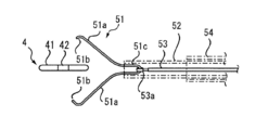
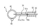
- the connecting hook 51 disposed at the sheath distal end of the clip device 5 includes a pair of arm portions 51a and 51a formed of an elastic body disposed in a substantially V shape toward the distal end.
- the inner sheath 52 it is possible to take two states, the open (open) state and the closed (closed) state.
- the front end portions of the arm portions 51a, 51a of the connection hook 51 are bent inward (sides facing each other) to form claw portions 51b, 51b, and the connection portion 21 of the clip main body 2 is gripped and connected It can be done.
- the base end portion of the connection hook 51 is a U-shaped portion 51c formed in a substantially U-shape continuously with the base end portions of the pair of arm portions 51a, 51a.
- the arm portions 51a, 51a including the claw portions 51b, 51b and the U-shaped portion 51c can be formed by appropriately bending (plastically deforming) one elongated plate made of an elastic body.
- the plate thickness of the plate constituting the connection hook 51 is about 0.20 to 0.24 mm, and the width is about 0.6 mm.
- stainless steel is used as the plate material.
- An annular member 53a formed in a substantially annular shape is integrally welded and fixed to the tip (distal end) of the drive wire 53 slidably inserted into the inner sheath 52 by laser welding or the like.
- the outer diameter of the annular member 53a is about 1.2 mm, and the inner diameter is about 0.8 to 1.0 mm.
- connection hook 51 is swingably attached to the distal end of the drive wire 53 by being inserted into the annular member 53a and disposed so that the U-shaped portion 51c is loosely fitted to the annular member 53a. .
- the connecting hook 51 is an arrow in FIG. 5C. It can be freely rotated in the a1 direction.
- the proximal end (proximal end) side of the outer sheath 54 is inserted into the reinforcing coil 55 and integrally fixed to the reinforcing coil 55.
- the reinforcing coil 55 is integrally fixed to the slider 56, and a portion on the distal end side of the base portion 57 is inserted and arranged inside the slider 56.
- the slider 56 is slidably positionable relative to the base portion 57 between a position moved to the distal end (distal end) side and two positions moved to the proximal end (proximal end) side It has become.
- the operating portion 58 is slidably held by the base portion 57, and the inner sheath 52 is fixed to the base portion 57.
- the proximal end of the drive wire 53 is fixed to the operation unit 58.
- the operation portion 58 When the operation portion 58 is slid to the distal end side (distal end side) with respect to the base portion 57, the inner sheath 52 is drawn into the drive wire 53, and the connection hook 51 at the tip of the drive wire 53 is the inner sheath 52. Protruding from the tip of the open leg by its own elasticity.
- the operation portion 58 When the operation portion 58 is slid to the base end side (proximal end side) with respect to the base portion 57, the drive wire 53 is drawn into the inner sheath 52, and the connection hook 51 at the tip of the drive wire 53 is the inner sheath By closing gradually into the inner sheath 52 and embedding in the inner sheath 52, the legs 52 are completely closed.
- the inner sheath 52 can be protruded from the tip of the outer sheath 54. Conversely, the distal end position of the slider 56 with respect to the base portion 57 The distal end of the inner sheath 52 can be stored (embedded) in the outer sheath 54 when it is slid to the
- connection hole 25 is formed in the connection plate 21 having a U-shaped cross section (see FIG. 1A, see FIG. 6A).
- the connection hook 51 of FIG. 5A is engaged with the connection hole 25 and the connection hook 51 is pulled into the inner sheath 52, whereby the connection hook 51 is closed, and the clip body 2 of the endoscope traction clip 1 is It is attached to the tip of the inner sheath 52 (see FIG. 6A).
- the distal end portion of the sheath portion of the clip device 5 on which the endoscope traction clip 1 is attached is positioned in the vicinity of the living tissue to be subjected to the dissection (peeling) treatment using an endoscope (not shown). Then, the endoscopic pull clip 1 is made to project from the distal end of the outer sheath 54 by sliding the outer sheath 54 to the proximal side. As a result, as shown in FIG. 6A, the arm plate portion 22 is opened by its own elasticity, and the loop portion 41 of the loop member 4 returns to its original shape by its own elasticity.
- the arm plate 22 With the arm plate 22 open, for example, as shown in FIG. 7A, it is positioned near the site (lesion) X where the mucous membrane (living tissue) is to be removed (exfoliated).
- the inner ring 52 is slid to the distal end side with respect to the drive wire 53, whereby the clamp ring 24 slides to the distal end side of the arm plate portion 22.
- the arm plate portions 22 gradually close (close to each other), and the mucous membrane on one side and the mucous membrane on the other side of the lesion X are gathered.
- the tightening ring 24 is moved to the grip portion 22b side of the arm plate portion 22 (see FIG. 1C), and the endoscope traction clip 1 (clip The grasping of the lesion X by the main body 2) is completed.
- the connection hook 51 is pushed out from the distal end of the inner sheath 52 and is opened, and the endoscope traction clip 1 ( The grip (engagement) of the clip main body 2) by the connection hook 51 is released, and the clipping of the lesion portion X of the endoscope traction clip 1 (clip main body 2) is completed.
- another clip (ordinary clip) 7 prepared separately is prepared separately, having the same configuration as the clip device 5 (or the clip device 5). Conveying the tip of the sheath of the clip device 5 attached to the tip of the clip device) to which the normal clip 7 is attached to the vicinity of an appropriate site (facing site) Y facing the lesion X Do.
- a clip having the same configuration as the clip main body 2 in which the coil spring 3 and the loop member 4 are removed from the endoscope pulling clip 1 shown in FIGS. 1A to 1C can be used.
- the loop portion 41 of the loop member 4 is scooped up with one of the pair of arm plate portions of the normal clip 7 (a part of the loop portion 41 is positioned at a portion between the pair of arm plate portions) While clipping the normal clip 7 to the facing site Y, as in the case of gripping the lesion X by the clip body 2 described above.
- the lesion X is pulled up (lifted) by the elastic force (tension) of the coil spring 3.
- the endoscope electric knife 8 is inserted through the endoscope, and the outer circumference of the lesion X is incised using the electric knife 8.
- the portion peeled by the incision of the lesion X does not block the view or interfere with the procedure.
- the entire circumference of the lesion X can be incised easily and reliably.
- the clip in a state in which the clip is not attached (connected) after the resection of the lesion X is completed and the endoscopic scalpel 8 is removed from the endoscope.
- the distal end of the device 5 (or a separately prepared clip device having the same configuration as the clip device 5) is positioned in the vicinity of the loop portion 41 of the loop member 4 being pulled, and the connection hook 51 is the distal end of the inner sheath 52 Make it project from the open leg.
- the position is finely adjusted so that an appropriate part of the loop portion 41 can be gripped.
- the inner sheath 52 is pushed out toward the distal end side with respect to the drive wire 53 to close the connection hook 51, and as shown in FIG. 8B, the appropriate part of the loop portion 41 is gripped by the connection hook 51.
- the loop portion 41 is in contact with the tip of the inner sheath 52.
- the drive wire 53 is slid relative to the inner sheath 52 toward the base end and pulled in, whereby the appropriate part of the loop portion 41 is connected to the tip of the inner sheath 52 and the connection hook. 51 and the shear force generated by Note that after the loop portion 41 is cut, the lesioned portion X can be extracted together with the pulling clip 1 by gripping with the connection hook 51 of the clip device 5 or a grasping forceps for an endoscope.
- the loop member 4 (loop portion 41) of the endoscope traction clip 1 is a clip device 5 for sliding the tightening ring 24 to close the pair of arm plate portions 22, 22 of the clip body 2 It is not necessary to prepare separately the cutting instrument for cutting the loop member 4, and the cost which a treatment requires can be reduced.
- the loop member 4 of the endoscope traction clip 1 according to the above-described embodiment integrally includes the loop portion 41 and the adapter portion 42, the adapter member as described in Patent Document 2 is used. There is no need to use it separately, and its configuration is simple.
- the outer shape of the loop portion 41 of the loop member 4 is substantially circular in plan view, but is not limited to this, and an oval, an oval, a polygon (for example, a rhombus), or these A portion of the above may be cut out and combined in two or more to form a loop.
- it may have a loop shape including a semicircular (arc-shaped) portion 41a and a semi-diamond (V-shaped) portion 41b.
- the position of the adapter 42 relative to the loop 41 may be anywhere because the loop 41 is substantially circular in the present embodiment, but if the loop 41 has a flat shape such as an ellipse, the long axis Preferably, it is provided in one of the directions.
- the loop portion 41 has a loop shape including a semicircular (or semi-elliptical) portion 41 a and a semi-rhombus (V-shaped) portion 41 b
- the adapter portion 42 is of the V-shaped portion 41 b. It is preferable to provide at the top.
- cross-sectional shape of the loop portion 41 is substantially circular in the present embodiment, the cross-sectional shape is not limited to this, and may be an oval, an oval, or a polygon.
- the loop portion 41 of the loop member 4 has a substantially circular cross section that is uniform over the entire circumference, but as shown in FIG. 4B, for example, the loop A portion of the loop portion 41 of the member 4 may be made smaller in diameter than the other portion, and a fragile portion (small diameter portion 41c) may be provided such that the portion can be cut with a weaker force than the other portion. . By cutting such a fragile portion with the clip device 5, the cutting can be easily performed with a weaker force.
- the small diameter portion 41c as the fragile portion is set to 12 o'clock with the adapter portion 42 set to the 3 o'clock position in consideration of the ease of approach by the connection hook 51.
- the fragile portion provided in the loop portion 41 is not limited to having a small diameter, and by changing the internal composition without changing the cross-sectional shape, a portion thereof is weaker than the other portions. It may be a weak part that can be disconnected by force.
- the joint portion boundary portion
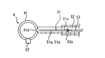
- a large diameter portion 41 d may be provided in which a part of the loop portion 41 of the loop member 4 is larger in diameter than the other portions.
- the large diameter portion 41 d is in the vicinity of the adapter portion 42 in consideration of the ease of approach to the loop portion 41 (portion other than the large diameter portion 41 d) by the connecting hook 51. It is provided in a length slightly shorter than the half circumference of the above, but may be formed in a different position or length. Further, at the boundary between the large diameter portion 41 d and the other loop portions 41, the diameter of the loop portion 41 is made to change in a tapered shape, but the diameter may be changed in a step shape, for example.
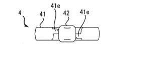
- FIGS. 9A to 9E two places close to the adapter part 42 are shown.
- the fragile portion 41e may be provided on the By providing the fragile portion at two places as described above, it is possible to select the one which is easy to cut at the time of cutting, so that the cutting operation can be facilitated. However, there is a possibility that the loop portion 41 may become insufficient in strength, or the arm portion of the clip through which the loop portion 41 passes (see the normal clip 7 in FIG. 7A) during the pulling operation or the like. These problems can be reduced by setting the fragile portion 41e at one location if there is a risk that it will get stuck in the work and interfere with the work.
- the loop portion 41 can be easily pulled back into the inner sheath 52 by gripping a part of the loop portion 41 with the connection hook 51 of the clip device 5.
- shape (loop shape, cross-sectional shape), size (loop diameter, cross-sectional diameter), material, molding method, molding condition (molding, in relation to the inner diameter of the tip of the inner sheath 52, etc. Temperature, pressure, etc. are set.
- the adapter portion 42 has a projection 42 b which protrudes to the inside of the loop portion 41.
- the adapter 42 including the projection 42 b is the tip of the inner sheath 52.
- the dimensions, rigidity, and the like are set in relation to the inner diameter of the distal end portion of the inner sheath 52 and the like so as not to be easily pulled into the inner sheath 52 by being caught.
- a part of the loop portion 41 is gripped by the connection hook 51 of the clip device 5, and the drive wire 53 is slid on the proximal end side with respect to the inner sheath 52 and pulled in.
- substantially the entire loop portion 41 is drawn into the inner sheath 52, and only the adapter portion 42 is hooked on the distal end portion of the inner sheath 52. Then, by applying a force in the direction of pulling in the loop portion 41, a tensile force is applied to the loop portion 41, and the loop portion 41 is cut in the fragile portion 41e.
- the loop portion 41 is gripped by the connection hook 51 of the clip device 5 and pulled in from the tip of the inner sheath 52, thereby exerting a cutting force on the loop portion 41 by the inner sheath 52 and the connection hook 51. I am trying to cut it. However, if the cutting of the loop portion 41 is repeatedly performed by the clip device 5, the arm portion 41 of the connection hook 51 may be deformed (plastic deformation), and may not be able to exhibit a sufficient gripping force necessary for the cutting. obtain.
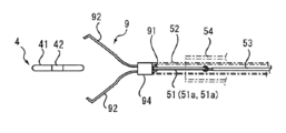
- the clip for cutting 9 is connected to the above-mentioned clip device 5, and the pair of arm parts 92, 92 of the clip for cutting 9 is closed to make a loop part.
- 41 is pulled from the tip of the outer sheath 54 in a state in which a part of 41 (preferably the fragile part if the loop 41 has a fragile part) is gripped, the tip of the outer sheath 54 and The cutting may be performed by the force generated by the cutting clip 9.
- the clip 9 for cutting the clip (generally used as a hemostatic clip etc.) of the structure similar to the clip main body 2 which removed the coil spring 3 and the loop member 4 from the pulling clip 1 for endoscopes shown to FIG. (The usual clip used for) can be used.
- FIG. 10A in a state where the connecting portion 91 of the cutting clip 9 is gripped by the pair of arm portions 51a, 51a of the connecting hook 51 and the cutting clip 9 is connected to the tip of the inner sheath 52.
- the position is finely adjusted so that the opening cutting clip 9 can grip an appropriate part of the loop portion 41.
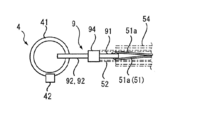
- the inner sheath 52 is pushed to the distal end side with respect to the drive wire 53, and the clamping ring 94 is slid to the distal end side to close the pair of arm portions 92, 92 of the cutting clip 9 as shown in FIG. 10B.
- an appropriate part of the loop portion 41 is held by the cutting clip 9 (in a clipping state).
- FIG. 10B As shown in FIG.
- the outer sheath 54 is slid to the distal end side with respect to the inner sheath 52, and the distal end of the outer sheath 54 is brought into contact with the loop portion 41.
- the inner sheath 52 is slid with the drive wire 53 to the proximal end side with respect to the outer sheath 54, and the cutting clip 9 is drawn into the outer sheath 54, whereby the appropriate part of the loop portion 41 is the outer It is cut by the force generated by the distal end of the sheath 54 and the cutting clip 9.
- the cutting clip 9 When the next cutting (cutting the loop portion of another pulling clip) is performed, the cutting clip 9 may be replaced with a new one, so as shown in FIGS. 8A to 8C, the connecting hook 51 is used. Compared to the case of cutting, even if cutting is repeated, there is no problem of hesitation, and cutting can always be properly performed.
- connection plate portion (connection portion) 22 Arm plate portion (arm portion) 22a ... proximal end 22b ... gripping part 23 ... claw part 24 ... clamping ring 25 ... connection hole 3 ... coil spring (connection member) 31 ... body portion 32 ... hook portion for clip 33 ... hook portion 4 for loop member 4 ... loop member 41 ... loop portion 42 ... adapter portion 42 a ... through hole for spring 41 c ...
- small diameter portion (weak portion) 41d large diameter portion 41e: fragile portion 5: clip device 51: connecting hook 52: inner sheath 53: drive wire 54: outer sheath 7: ordinary clip 8: electric scalpel for endoscope 9: cutting clip X: lesion Part Y ... opposite part
Landscapes
- Health & Medical Sciences (AREA)
- Life Sciences & Earth Sciences (AREA)
- Surgery (AREA)
- Heart & Thoracic Surgery (AREA)
- Engineering & Computer Science (AREA)
- Biomedical Technology (AREA)
- Nuclear Medicine, Radiotherapy & Molecular Imaging (AREA)
- Medical Informatics (AREA)
- Molecular Biology (AREA)
- Animal Behavior & Ethology (AREA)
- General Health & Medical Sciences (AREA)
- Public Health (AREA)
- Veterinary Medicine (AREA)
- Surgical Instruments (AREA)
- Endoscopes (AREA)
Priority Applications (3)
| Application Number | Priority Date | Filing Date | Title |
|---|---|---|---|
| CN201880048760.6A CN110944588B (zh) | 2017-09-29 | 2018-10-01 | 内窥镜用牵引夹具 |
| EP18861095.0A EP3689254A4 (de) | 2017-09-29 | 2018-10-01 | Zugklemme für endoskop |
| JP2019545208A JP7140130B2 (ja) | 2017-09-29 | 2018-10-01 | 内視鏡用牽引クリップ |
Applications Claiming Priority (2)
| Application Number | Priority Date | Filing Date | Title |
|---|---|---|---|
| JP2017-191971 | 2017-09-29 | ||
| JP2017191971 | 2017-09-29 |
Publications (1)
| Publication Number | Publication Date |
|---|---|
| WO2019066084A1 true WO2019066084A1 (ja) | 2019-04-04 |
Family
ID=65903334
Family Applications (1)
| Application Number | Title | Priority Date | Filing Date |
|---|---|---|---|
| PCT/JP2018/036682 Ceased WO2019066084A1 (ja) | 2017-09-29 | 2018-10-01 | 内視鏡用牽引クリップ |
Country Status (4)
| Country | Link |
|---|---|
| EP (1) | EP3689254A4 (de) |
| JP (1) | JP7140130B2 (de) |
| CN (1) | CN110944588B (de) |
| WO (1) | WO2019066084A1 (de) |
Cited By (7)
| Publication number | Priority date | Publication date | Assignee | Title |
|---|---|---|---|---|
| WO2021005698A1 (ja) * | 2019-07-09 | 2021-01-14 | 株式会社オクムラ | デタッチャブル・マルチリング・トラクション・デバイス |
| ES2817674R1 (es) * | 2018-07-20 | 2021-10-21 | Micro Tech Nanjing Co Ltd | Aparato de traccion y anillo de traccion para aparato de traccion |
| WO2022124277A1 (ja) * | 2020-12-07 | 2022-06-16 | 株式会社常光 | 内視鏡用施術部牽引部材 |
| CN114980818A (zh) * | 2019-12-05 | 2022-08-30 | 波士顿科学国际有限公司 | 组织牵引装置、系统和方法 |
| JPWO2022209691A1 (de) * | 2021-03-31 | 2022-10-06 | ||
| JP2025504901A (ja) * | 2022-02-09 | 2025-02-19 | ボストン サイエンティフィック サイムド,インコーポレイテッド | 組織牽引デバイスおよびそのための送達システム |
| US12484910B2 (en) | 2021-03-31 | 2025-12-02 | Zeon Corporation | Endoscopic treatment tool |
Families Citing this family (1)
| Publication number | Priority date | Publication date | Assignee | Title |
|---|---|---|---|---|
| US20250221697A1 (en) * | 2024-01-05 | 2025-07-10 | Boston Scientific Medical Device Limited | Devices, systems, and methods for tissue traction |
Citations (4)
| Publication number | Priority date | Publication date | Assignee | Title |
|---|---|---|---|---|
| JPH07155333A (ja) * | 1993-11-22 | 1995-06-20 | Kaigen:Kk | 静脈瘤用結紮器 |
| JP2008062004A (ja) | 2006-09-09 | 2008-03-21 | Taichi Sakamoto | 医療用把持具、医療用処置装置及び医療用クリップ |
| JP2008155006A (ja) * | 2006-11-28 | 2008-07-10 | Nobuyuki Sakurazawa | 粘膜牽引具 |
| JP2015192726A (ja) | 2014-03-31 | 2015-11-05 | 日本ゼオン株式会社 | 内視鏡用バネ付きクリップ |
Family Cites Families (4)
| Publication number | Priority date | Publication date | Assignee | Title |
|---|---|---|---|---|
| JP4261294B2 (ja) * | 2003-09-04 | 2009-04-30 | Hoya株式会社 | 内視鏡用クリップ装置 |
| CN101227864A (zh) * | 2005-08-11 | 2008-07-23 | 奥林巴斯株式会社 | 内窥镜用处理器具 |
| AU2009335901B2 (en) * | 2008-12-19 | 2013-09-19 | Cook Medical Technologies Llc | Clip devices and methods of delivery and deployment |
| JP5750620B2 (ja) * | 2013-05-07 | 2015-07-22 | オリンパス株式会社 | 内視鏡処置具 |
-
2018
- 2018-10-01 WO PCT/JP2018/036682 patent/WO2019066084A1/ja not_active Ceased
- 2018-10-01 EP EP18861095.0A patent/EP3689254A4/de active Pending
- 2018-10-01 CN CN201880048760.6A patent/CN110944588B/zh active Active
- 2018-10-01 JP JP2019545208A patent/JP7140130B2/ja active Active
Patent Citations (4)
| Publication number | Priority date | Publication date | Assignee | Title |
|---|---|---|---|---|
| JPH07155333A (ja) * | 1993-11-22 | 1995-06-20 | Kaigen:Kk | 静脈瘤用結紮器 |
| JP2008062004A (ja) | 2006-09-09 | 2008-03-21 | Taichi Sakamoto | 医療用把持具、医療用処置装置及び医療用クリップ |
| JP2008155006A (ja) * | 2006-11-28 | 2008-07-10 | Nobuyuki Sakurazawa | 粘膜牽引具 |
| JP2015192726A (ja) | 2014-03-31 | 2015-11-05 | 日本ゼオン株式会社 | 内視鏡用バネ付きクリップ |
Cited By (13)
| Publication number | Priority date | Publication date | Assignee | Title |
|---|---|---|---|---|
| US11925343B2 (en) | 2018-07-20 | 2024-03-12 | Micro-Tech (Nanjing) Co., Ltd. | Traction apparatus and traction ring for traction apparatus |
| ES2817674R1 (es) * | 2018-07-20 | 2021-10-21 | Micro Tech Nanjing Co Ltd | Aparato de traccion y anillo de traccion para aparato de traccion |
| AU2023202699B2 (en) * | 2019-07-09 | 2025-05-15 | Okumara Co., Ltd. | Detachable multi-ring traction device |
| WO2021005698A1 (ja) * | 2019-07-09 | 2021-01-14 | 株式会社オクムラ | デタッチャブル・マルチリング・トラクション・デバイス |
| CN114980818A (zh) * | 2019-12-05 | 2022-08-30 | 波士顿科学国际有限公司 | 组织牵引装置、系统和方法 |
| JP2024056976A (ja) * | 2019-12-05 | 2024-04-23 | ボストン サイエンティフィック サイムド,インコーポレイテッド | 組織牽引装置、システムおよび方法 |
| JP7520311B2 (ja) | 2020-12-07 | 2024-07-23 | 株式会社常光 | 内視鏡用施術部牽引部材 |
| JPWO2022124277A1 (de) * | 2020-12-07 | 2022-06-16 | ||
| WO2022124277A1 (ja) * | 2020-12-07 | 2022-06-16 | 株式会社常光 | 内視鏡用施術部牽引部材 |
| WO2022209691A1 (ja) | 2021-03-31 | 2022-10-06 | 日本ゼオン株式会社 | 内視鏡用処置具 |
| JPWO2022209691A1 (de) * | 2021-03-31 | 2022-10-06 | ||
| US12484910B2 (en) | 2021-03-31 | 2025-12-02 | Zeon Corporation | Endoscopic treatment tool |
| JP2025504901A (ja) * | 2022-02-09 | 2025-02-19 | ボストン サイエンティフィック サイムド,インコーポレイテッド | 組織牽引デバイスおよびそのための送達システム |
Also Published As
| Publication number | Publication date |
|---|---|
| EP3689254A4 (de) | 2021-09-22 |
| CN110944588B (zh) | 2023-06-09 |
| CN110944588A (zh) | 2020-03-31 |
| JP7140130B2 (ja) | 2022-09-21 |
| EP3689254A1 (de) | 2020-08-05 |
| JPWO2019066084A1 (ja) | 2020-11-05 |
Similar Documents
| Publication | Publication Date | Title |
|---|---|---|
| WO2019066084A1 (ja) | 内視鏡用牽引クリップ | |
| US8298249B2 (en) | Medical ligating apparatus | |
| KR101038134B1 (ko) | 결찰 장치 | |
| WO2012101999A1 (ja) | 縫合装置 | |
| JP2005329240A (ja) | 治療用処置装置 | |
| JP6149779B2 (ja) | 内視鏡用バネ付きクリップ | |
| US9693769B2 (en) | Suture device | |
| US20170281176A1 (en) | Medical clip device, method for producing medical clip device and method for operating thereof | |
| JP6432175B2 (ja) | 内視鏡用処置具 | |
| WO2017111163A1 (ja) | 内視鏡用縫合糸結紮具 | |
| JP2019520904A (ja) | 止血クリップの為の再搭載可能なアプリケータ | |
| JP2007275542A (ja) | クリップ装置 | |
| KR101601911B1 (ko) | 내시경용 처치구 장치 | |
| JP7302481B2 (ja) | 内視鏡用処置具 | |
| CN114929120A (zh) | 内窥镜用缝合线结扎器具及结扎装置 | |
| JP7157369B2 (ja) | 内視鏡用牽引クリップ | |
| JP7087496B2 (ja) | 内視鏡用牽引クリップ | |
| TWI909024B (zh) | 內視鏡用處置器械 | |
| JP4105406B2 (ja) | 内視鏡用クリップ装置 | |
| JP2019177049A (ja) | 医療用縫合装置 | |
| EP3520717B1 (de) | Clipentfernungsvorrichtung | |
| JP4542562B2 (ja) | 医療用結紮具 | |
| WO2024024931A1 (ja) | 内視鏡用牽引クリップ | |
| JP2018061673A (ja) | 留置用クリップ | |
| JP4500297B2 (ja) | 医療用結紮具 |
Legal Events
| Date | Code | Title | Description |
|---|---|---|---|
| 121 | Ep: the epo has been informed by wipo that ep was designated in this application |
Ref document number: 18861095 Country of ref document: EP Kind code of ref document: A1 |
|
| ENP | Entry into the national phase |
Ref document number: 2019545208 Country of ref document: JP Kind code of ref document: A |
|
| NENP | Non-entry into the national phase |
Ref country code: DE |
|
| ENP | Entry into the national phase |
Ref document number: 2018861095 Country of ref document: EP Effective date: 20200429 |