WO2019069496A1 - Dispositif d'affichage - Google Patents
Dispositif d'affichage Download PDFInfo
- Publication number
- WO2019069496A1 WO2019069496A1 PCT/JP2018/016386 JP2018016386W WO2019069496A1 WO 2019069496 A1 WO2019069496 A1 WO 2019069496A1 JP 2018016386 W JP2018016386 W JP 2018016386W WO 2019069496 A1 WO2019069496 A1 WO 2019069496A1
- Authority
- WO
- WIPO (PCT)
- Prior art keywords
- light
- entity
- backlight
- image display
- display unit
- Prior art date
- Legal status (The legal status is an assumption and is not a legal conclusion. Google has not performed a legal analysis and makes no representation as to the accuracy of the status listed.)
- Ceased
Links
Images





Classifications
-
- B—PERFORMING OPERATIONS; TRANSPORTING
- B60—VEHICLES IN GENERAL
- B60K—ARRANGEMENT OR MOUNTING OF PROPULSION UNITS OR OF TRANSMISSIONS IN VEHICLES; ARRANGEMENT OR MOUNTING OF PLURAL DIVERSE PRIME-MOVERS IN VEHICLES; AUXILIARY DRIVES FOR VEHICLES; INSTRUMENTATION OR DASHBOARDS FOR VEHICLES; ARRANGEMENTS IN CONNECTION WITH COOLING, AIR INTAKE, GAS EXHAUST OR FUEL SUPPLY OF PROPULSION UNITS IN VEHICLES
- B60K35/00—Instruments specially adapted for vehicles; Arrangement of instruments in or on vehicles
- B60K35/20—Output arrangements, i.e. from vehicle to user, associated with vehicle functions or specially adapted therefor
- B60K35/21—Output arrangements, i.e. from vehicle to user, associated with vehicle functions or specially adapted therefor using visual output, e.g. blinking lights or matrix displays
- B60K35/22—Display screens
-
- G—PHYSICS
- G01—MEASURING; TESTING
- G01D—MEASURING NOT SPECIALLY ADAPTED FOR A SPECIFIC VARIABLE; ARRANGEMENTS FOR MEASURING TWO OR MORE VARIABLES NOT COVERED IN A SINGLE OTHER SUBCLASS; TARIFF METERING APPARATUS; MEASURING OR TESTING NOT OTHERWISE PROVIDED FOR
- G01D11/00—Component parts of measuring arrangements not specially adapted for a specific variable
- G01D11/28—Structurally-combined illuminating devices
-
- G—PHYSICS
- G01—MEASURING; TESTING
- G01D—MEASURING NOT SPECIALLY ADAPTED FOR A SPECIFIC VARIABLE; ARRANGEMENTS FOR MEASURING TWO OR MORE VARIABLES NOT COVERED IN A SINGLE OTHER SUBCLASS; TARIFF METERING APPARATUS; MEASURING OR TESTING NOT OTHERWISE PROVIDED FOR
- G01D7/00—Indicating measured values
-
- G—PHYSICS
- G09—EDUCATION; CRYPTOGRAPHY; DISPLAY; ADVERTISING; SEALS
- G09F—DISPLAYING; ADVERTISING; SIGNS; LABELS OR NAME-PLATES; SEALS
- G09F13/00—Illuminated signs; Luminous advertising
- G09F13/04—Signs, boards or panels, illuminated from behind the insignia
-
- G—PHYSICS
- G02—OPTICS
- G02F—OPTICAL DEVICES OR ARRANGEMENTS FOR THE CONTROL OF LIGHT BY MODIFICATION OF THE OPTICAL PROPERTIES OF THE MEDIA OF THE ELEMENTS INVOLVED THEREIN; NON-LINEAR OPTICS; FREQUENCY-CHANGING OF LIGHT; OPTICAL LOGIC ELEMENTS; OPTICAL ANALOGUE/DIGITAL CONVERTERS
- G02F1/00—Devices or arrangements for the control of the intensity, colour, phase, polarisation or direction of light arriving from an independent light source, e.g. switching, gating or modulating; Non-linear optics
- G02F1/01—Devices or arrangements for the control of the intensity, colour, phase, polarisation or direction of light arriving from an independent light source, e.g. switching, gating or modulating; Non-linear optics for the control of the intensity, phase, polarisation or colour
- G02F1/13—Devices or arrangements for the control of the intensity, colour, phase, polarisation or direction of light arriving from an independent light source, e.g. switching, gating or modulating; Non-linear optics for the control of the intensity, phase, polarisation or colour based on liquid crystals, e.g. single liquid crystal display cells
Definitions
- the present disclosure relates to a display device that displays an image.
- Patent Document 1 discloses a display device provided with an image display unit, an entity, a first backlight, and a second backlight.
- the image display unit displays an image in the display area.
- the entity is disposed on the back side of the image display unit, and is provided to be able to display through the image display unit.
- the first backlight is capable of emitting light from the rear side to both the image display unit and the entity.
- the second backlight is disposed between the image display unit and the entity, and can emit light to the image display unit from the back side.
- the second backlight includes a light transmitting plate and a light source unit.
- the light transmitting plate is disposed so as to overlap with the display region and has light transmitting property.
- the light source unit is configured to provide light to the inside of the light transmission plate through the light incident portion of the light transmission plate. Furthermore, emboss processing is performed on the plate surface of the light transmission plate, and light provided by the light source unit is irregularly reflected.
- the second backlight is intended to switch between display and non-display of the entity.
- Patent Document 1 when the second backlight is turned on, the entity is also illuminated due to the irregular reflection of light, and it is difficult to completely hide the entity.
- the second backlight even when the second backlight is turned off, since the light transmission plate is turbid like glazed glass due to emboss processing, the entity is not clearly visible through the light transmission plate, and Visibility was not enough. Therefore, there is room for improvement in the appearance of the display device.
- One object disclosed is to provide a display device that looks good.
- the display device includes An image display unit for displaying an image in a display area; An entity disposed on the back side of the image display unit and provided to be able to be displayed through the image display unit; A first backlight capable of emitting light from the back side to both the image display unit and the substance; A second backlight disposed between the image display unit and the entity and capable of emitting light from the back side to the image display unit;
- the second backlight is A translucent plate disposed so as to overlap the display area, and having a translucent property;
- a light source unit for providing light to the inside of the light transmitting plate via the light receiving portion of the light transmitting plate;
- the light transmitting plate has a shape recessed from the plate surface, and a plurality of light reflecting elements that specularly reflect the light provided to the inside toward the image display unit are arranged side by side in the real object overlapping region overlapping the real object .
- the plurality of light reflecting elements recessed from the plate surface are arranged side by side in the real object overlapping region overlapping with the real object, and the light provided inside the plate is directed to the image display unit side Each is specularly reflected.
- the second backlight is turned on, the light provided to the inside of the plate is specularly reflected to the image display unit side, so it is possible to suppress the illumination of the entity located on the opposite side to the image display unit. Therefore, the second backlight can sufficiently hide the entity.
- a display device with a good appearance can be provided.
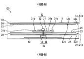
- FIG. 4 is a cross-sectional view taken along line IV-IV of FIG. 3;
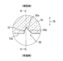
- FIG. 5 is a cross-sectional view taken along line VV of FIG. 4;
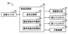
- It is a block diagram for demonstrating the control unit of 1st Embodiment.
- It is a front view which shows the example of a display in the display apparatus of 1st Embodiment. It is a front view which shows the other display example in the display apparatus of 1st Embodiment.
- a display for a vehicle is used in a vehicle and installed on an instrument panel facing a seat on which an occupant who views the device 100 sits. It is an apparatus.
- the display device 100 can display information of the vehicle toward the viewing side where the occupant is located.
- the information to be displayed includes, for example, the vehicle speed, the engine speed, the fuel remaining amount, the water temperature of the engine coolant, the gear shift range, the traveling distance and the like.
- various information such as road information, visibility auxiliary information, electronic mail and the like can be mentioned.
- Such a display device 100 includes an image display unit 10, a first backlight 20, an entity 30, a movable mechanism 40, a second backlight 50, a control unit 60, and the like.
- the image display unit 10 is a panel-like display element that displays an image in the display area 11.
- the image display unit 10 is a transmissive liquid crystal panel using thin film transistors (TFTs), and has a plurality of pixels arranged in a two-dimensional direction in the rectangular display area 11.
- TFTs thin film transistors
- An active matrix liquid crystal panel is employed.
- a pair of controllable transparent electrodes for each pixel is formed between a pair of polarizing films whose polarization axes are substantially orthogonal to each other with a liquid crystal layer in which liquid crystal is enclosed. ing.
- the present image display unit 10 for example, when the voltage between the transparent electrodes is equal to or less than a predetermined value, a state in which the alignment direction of the liquid crystal is twisted between the transparent electrodes based on the rubbing direction of the alignment film. It becomes. In this state, light incident on the image display unit from the back side opposite to the viewing side is transmitted. On the other hand, when the voltage between the transparent electrodes is equal to or more than a predetermined value, the twist in the alignment direction of the liquid crystal is eliminated. In this state, light entering the image display unit from the back side is blocked. That is, the transmittance of each pixel changes according to the voltage between the transparent electrodes.
- the first backlight 20 is disposed on the back side of the image display unit 10, the second backlight 50, and the entity 30, and includes the light source unit 21, the light guide plate 23, the reflection plate 24, and the diffusion plate 25. It is an edge light type backlight.
- the light source unit 21 has a plurality of light emitting elements 21 a.
- Each light emitting element 21 a is, for example, a white light emitting diode element, and a plurality of light emitting elements 21 a are arranged to face the side surface of the light guide plate 23.
- the light emitted from each light emitting element 21a is made to enter the inside of the plate with the side surface of the light guide plate 23 as the incident part 23a.
- the light source unit 21 provides light to the inside of the light guide plate 23 through the incident unit 23 a.
- the light guide plate 23 is formed in, for example, a rectangular plate shape of a translucent synthetic resin.
- the reflecting plate 24 is formed, for example, of a synthetic resin in the form of a film, and is disposed on the back side of the light guide plate 23 by adhesion.
- the diffusion plate 25 is formed of, for example, a synthetic resin in a plate shape, and is disposed so as to adhere to the viewing side of the light guide plate 23.
- the light incident on the light guide plate 23 is reflected by the reflection plate 24, diffused by the diffusion plate 25, and emitted from the entire diffusion plate 25 to the viewing side.
- the first backlight 20 is formed to be able to emit light to the image display unit 10 and the entity 30 from the back side.
- the entity 30 is disposed on the rear side of the image display unit 10 and the second backlight 50 and on the viewing side of the first backlight 20.
- the entity 30 of the present embodiment is configured of an index plate 31 and an entity pointer 33.
- the index plate 31 is formed in a translucent disk shape, for example, by a synthetic resin such as an acrylic resin.
- the inner circumferential portion 31 a of the index plate 31 is formed in a flat plate shape.
- an index as an indication target by the real pointer 33 is formed in the outer peripheral portion 31 b of the index plate 31, an index as an indication target by the real pointer 33 is formed.
- the index of the present embodiment includes a plurality of solid scales 31c.
- the plurality of solid scales 31c are arrayed in an annular shape, and are formed in the shape of a scale protruding toward the viewing side with respect to the inner peripheral portion 31a. For example, light shielding printing or painting is applied to the top of the solid scale 31 c facing the viewing side.
- the substantial pointer 33 is formed of, for example, a synthetic resin in a light shielding property, and is disposed closer to the visual recognition side than the inner circumferential portion 31 a so as to be displayed overlapping the inner circumferential portion 31 a of the index plate 31.
- the actual pointer 33 is formed in the shape of a needle that can indicate a solid scale 31c as an index, and is rotatable. As a result, the actual pointer 33 can display information according to the designated position.
- the movable mechanism 40 is a mechanism for moving the entity 30, and in the present embodiment, in particular, in the present embodiment, it is a pivoting mechanism for pivoting the pointer 33.
- the movable mechanism 40 has a stepping motor 41 and a rotating shaft 42.
- the stepping motor 41 is held by the circuit board 43 on the rear side of the first backlight 20.
- the rotating shaft 42 is disposed through a through hole opened in the first backlight 20, and connects the stepping motor 41 and the substantial pointer 33.
- the actual pointer 33 is adapted to rotate around the rotation shaft 42 in accordance with the output of the stepping motor 41.
- the second backlight 50 is disposed on the rear side of the image display unit 10 and on the viewing side of the first backlight 20 and the entity 30.
- the second backlight 50 includes a light source unit 51 and a light transmitting plate 53.
- the light source unit 51 has a plurality of light emitting elements 51a.
- Each light emitting element 51 a is, for example, a white light emitting diode element in the same manner as the light emitting element 21 a of the first backlight 20, and a plurality of light emitting elements 51 a are arranged to face the side surface of the light transmitting plate 53.
- the light emitted from each light emitting element 51a is made to enter the inside of the plate with the side surface of the light transmitting plate 53 as the incident part 53a.
- the light source unit 51 provides light to the inside of the light transmitting plate 53 via the incident portion 53a.
- the light transmitting plate 53 is made of, for example, a synthetic resin such as an acrylic resin to be light transmitting, and has a flat plate shape having a front plate surface 53b on the viewing side and a back plate surface 53c on the rear side.
- the light transmitting plate 53 is provided substantially in parallel with the light guide plate 23 of the image display unit 10 and the first backlight 20, and in the present embodiment, the front plate surface 53b is bonded to the back side of the image display unit 10. It is formed.
- the light transmitting plate 53 is disposed so as to overlap the entire area of the display area 11 of the image display unit 10.
- the light transmitting plate 53 and the entity 30 are disposed apart from each other.
- an area overlapping with the display area 11 of the image display unit 10 is defined as a display overlapping area DOR.
- a region overlapping with the entity 30 is defined as an entity overlapping region OOR.
- the entity 30 is formed corresponding to the central portion 11a which is a part of the display area 11, a part of the center of the display overlap area DOR corresponds to the entity overlap area OOR. ing.
- the light transmitting plate 53 has a plurality of light reflecting elements 55 arranged side by side over the entire display overlapping area DOR including the real object overlapping area OOR.
- Each light reflecting element 55 is an element having a shape indented from the back plate surface 53c into the inside of the plate, and is an element having a minute size with a recess depth of 100 ⁇ m or less, more preferably about 5 to 20 ⁇ m.
- Each light reflection element 55 is configured to specularly reflect the light provided inside the plate by the light source unit 51 to the image display unit 10 side (in other words, the viewing side). Specular reflection is also generally referred to as specular reflection.
- the range in which the dot hatching is performed in FIGS. 1 and 2 is the range in which the light reflecting element 55 is disposed on the back plate surface 53c.
- each light reflecting element 55 is formed in a triangular pyramid shape and recessed from the back plate surface 53 c to the front plate surface 53 b.
- Each light reflection element 55 has an isosceles triangle shape in a plan view seen from a line of sight along the thickness direction TD of the light transmission plate 53 perpendicular to the back plate surface 53c, as particularly shown in FIG. .
- Each light reflecting element 55 has a reflecting surface 56 formed of two inclined surfaces 56 a and an element back surface 57.
- the two inclined surfaces 56a are respectively disposed at positions adjacent to equal sides in an isosceles triangle on the plan view.
- the two inclined surfaces 56a are two surfaces facing the incident part 53a side where the light from the light source part 51 enters among the surfaces by the triangular pyramid light reflecting element 55, and the outer contour is a triangular plane and mirror surface Are respectively formed.
- Each light reflecting element 55 has a linear connection side 56b connecting two inclined surfaces 56a along a cross section bisecting the apex angle (or the base) of the isosceles triangle shape on the plan view. ing.
- the connection side 56b is inclined so as to be further separated from the incident portion 53a as it goes from the back plate surface 53c side to the front plate surface 53b side, and in particular, as shown in FIG. For example, the inclination angle is 45 degrees.
- Each inclined surface 56a is also inclined so as to be further separated from the incident portion 53a as it goes from the back plate surface 53c side to the front plate surface 53b side, similarly to the connection side 56b.
- Each inclined surface 56a also has an inclination angle of, for example, 45 degrees with respect to the thickness direction TD on a parallel cross section parallel to the cross section which bisects the above-mentioned apex angle.
- the two inclined surfaces 56a are set to have different directions. Specifically, the two inclined surfaces 56a face each other diagonally in the form of an isosceles-triangular equal-side inclination on the plan view.
- the triangular-pyramidal light reflecting element 55 includes the concave bottom 55a forming the deepest bottom, and is particularly visible on the vertical cross section perpendicular to the cross section bisecting the above-mentioned apex angle.
- the two inclined surfaces 56a are inclined in opposite directions with an inclination angle of, for example, 10 degrees with respect to the back plate surface 53c.
- the element back surface 57 is disposed at a position adjacent to the bottom of the isosceles triangle on the plan view, and is formed to face the opposite side to the incident portion 53a.
- the element back surface 57 is formed such that the outer contour is a triangular flat surface and a mirror surface.
- the element back surface 57 is inclined so as to approach the incident portion 53a from the back plate surface 53c side toward the front plate surface 53b side, and forms, for example, an inclination angle of 5 degrees with respect to the thickness direction TD. That is, the inclination angle of the element back surface 57 is set smaller than the inclination angle of the reflecting surface 56. Therefore, when the passenger who is a viewer visually recognizes the light transmitting plate 53 along the thickness direction TD, the area in which the element back surface 57 is visually recognized is extremely small.
- the light reflecting elements 55 are mutually separated by the arrangement pitches PT1 and PT2 respectively set in the arrangement directions D1 and D2 through the mirror-like flat portions 59 formed flat on the back plate surface 53c. They are separated and placed one by one in isolation.
- the arrangement direction D1 is along the main traveling direction PD of the provided light, and the arrangement direction D2 is substantially perpendicular to the arrangement direction D1.
- the plurality of light reflecting elements 55 are arranged in a so-called zigzag shape in which the positions of the concave bottom portions 55a are shifted by half the arrangement pitch PT1, PT2 for each row.
- the arrangement pitches PT1 and PT2 of the light reflection elements 55 are set to extremely small values with respect to the arrangement pitch of the light emitting elements 51a of the light source unit 51.
- the arrangement structure of the light reflecting elements 55 is set in the entire display overlapping area DOR described above, but the back surface occupied by the plurality of light reflecting elements 55 in the entire display overlapping area DOR including the entity overlapping area OOR.
- the area on the plate surface 53 c is smaller than the area on the back plate surface 53 c occupied by the flat portion 59. More specifically, the area on the back plate surface 53c occupied by the plurality of light reflecting elements 55 in the arrangement structure, that is, the density of the light reflecting elements 55 is 10% or less.
- the portion excluding the area occupied by the light reflecting element 55 in the arrangement structure is occupied by the flat portion 59.
- the light provided from the light source unit 51 via the incident unit 53a mainly travels in the plate along the traveling direction PD. More specifically, the provided light includes light linearly traveling along the inside of the plate along the front surface 53b and the back surface 53c, and travels in a zigzag while being reflected by the respective surfaces 53b and 53c. including. That is, although the provided light includes light traveling in a direction slightly deviated from the traveling direction PD, the light travels along the traveling direction PD on average.
- the reflection surface 56 is set at an angle inclined with respect to the back plate surface 53c, whereby the light is specularly reflected to the viewing side.
- the light thus specularly reflected enters the image display unit 10 through the front plate surface 53b. Therefore, the second backlight 50 can emit light to the image display unit 10 from the back side.
- control unit 60 is configured of, for example, a changeover switch 61, a control circuit unit 62, and the like.
- the changeover switch 61 is disposed so as to be operable by the occupant, but may be automatically switched according to a predetermined condition.
- the control circuit unit 62 is an electronic circuit in which at least one processor, a memory, an input / output interface and the like are mounted on a substrate.
- the processor can execute various processes by executing a computer program stored in the memory based on a signal input through the input / output interface.
- the control circuit unit 62 is electrically connected to the changeover switch 61, the image display unit 10, the first backlight 20, the second backlight 50, and the movable mechanism 40.
- the control circuit unit 62 has a display switching unit 63, an entity display operation unit 64, and an entity display restriction unit 65 as functional blocks constructed mainly of such an electronic circuit.
- the display switching unit 63 switches the display of the display device 100 based on the electrical signal input from the switch 61. Specifically, the display switching unit 63 switches to display control by the entity display operating unit 64 when the switch 61 is turned on, and switches to display control by the entity display restricting unit 65 when the switch 61 is turned off. .
- the entity display operation unit 64 turns on the first backlight 20 and turns off the second backlight 50 so that the entity 30 is displayed through the image display unit 10.
- the light emitting elements 51a of the second backlight 50 are turned off, light is not provided inside the light transmitting plate 53.
- each light reflecting element 55 is as if it does not exist because it is formed through the minute size and the flat portion 59.
- high transparency is realized in the light transmitting plate 53 by forming the reflecting surface 56 and the element back surface 57 in a mirror shape.
- the entity display operation unit 64 is a back side of the transmittance of the pixels of the central portion 11a overlapping the entity 30 in the display area 11 of the image display unit 10. It is necessary to control so high that the entity 30 of the object 30 becomes visible.
- the entity display operation unit 64 causes the central portion 11 a to display the index plate 31 and the entity pointer 33 as the entity 30.
- the portion of the index plate 31 set to be translucent transmits the light from the first backlight 20, and the portion set to light shielding of the index plate 31 and the solid pointer 33 from the first backlight 20 And the display of the entity 30 with three-dimensional and high contrast is realized.
- the transmittance of the pixels may be set low to enhance the display of the entity 30.
- the display of the car navigation and the display of the character information may be displayed by an image.
- the range indicated by hatching in FIGS. 7 and 8 is a range in which the entity 30 is displayed on the rear side of the image display unit 10.
- the entity display restriction unit 65 turns off the first backlight 20 and turns on the second backlight 50 to restrict display of the entity 30 through the image display unit 10.
- the entity 30 is not illuminated from the back side.
- each light emitting element 51a of the second backlight 50 is turned on, the light provided inside the light transmitting plate 53 is thereby specularly reflected by the reflecting surface 56 of each light reflecting element 55 to the image display unit 10 side. Ru. Due to such regular reflection, even when the area occupied by the light reflecting element 55 is relatively small, light is efficiently irradiated to the image display unit 10 from the back side.
- the light is restricted from being reflected toward the entity 30 by the configuration of the reflecting surface 56 of the light reflecting element 55, the entity 30 is difficult to be irradiated with light.
- the entity 30 is hardly visible through the image display unit 10, and the light from the second backlight 50 is uniformly emitted to the entire display region 11, whereby the image display unit 10 has a high degree of freedom.
- Image display is realized in the entire display area 11.
- the entity display restriction unit 65 causes the central portion 11a to display the display of the character information as an image. Furthermore, the entity display restriction unit 65 causes the pointer image and the index image to be displayed as an image in the other part of the display area.
- step S10 the display switching unit 63 acquires the state of the switch 61, and determines whether the switch is in the on state. If an affirmative determination is made in step S10, the process moves to step S20. If a negative determination is made in step S10, the process moves to step S30.
- step S20 display control is performed by the entity display operation unit 64. That is, the first backlight 20 is turned on and the second backlight 50 is turned off. Then, the transmittance of each pixel is set in the image display unit 10 as in the display examples shown in FIGS. A series of processing is ended by step S20.
- step S30 display control is performed by the entity display restriction unit 65. That is, the first backlight 20 is turned off and the second backlight 50 is turned on. Then, the transmittance of each pixel is set in the image display unit 10 as in the display example shown in FIG. A series of processing is ended by step S30.
- the plurality of light reflecting elements 55 recessed from the back plate surface 53 c in the light transmitting plate 53 are arranged in a real object overlapping area OOR overlapping the real object 30 and the light provided inside the plate is The light is specularly reflected on the image display unit 10 side.
- the second backlight 50 is turned on, the light provided inside the plate is specularly reflected to the image display unit 10 side, so that the object 30 located on the opposite side to the image display unit 10 can be illuminated. Be suppressed. Therefore, the second backlight 50 can sufficiently hide the entity 30.
- the display device 100 with a good appearance can be provided.
- the first embodiment since a plurality of light reflecting elements 55 having the specular reflecting surface 56 are arranged in the real object overlapping region OOR of the light transmitting plate 53, embossing is performed in the real object overlapping region OOR. Can be suppressed to enhance the transparency of the light transmitting plate 53. Therefore, when the second backlight 50 is turned off, the entity 30 can be more clearly viewed through the light transmitting plate 53, and the visibility of the entity 30 is enhanced.
- the light reflecting elements 55 are spaced apart from each other by the flat portion 59. In this way, when the second backlight 50 is turned off, the entity 30 can be clearly viewed through the flat portion 59 even if the light reflecting element 55 exists in places of the entity overlapping region OOR. Is possible. Therefore, the appearance of the display device 100 is exceptional.
- the area occupied by the plurality of light reflecting elements 55 is smaller than the area occupied by the flat portion 59. Since the area occupied by the flat portion 59 is large, the transparency of the light transmitting plate 53 is further enhanced. As a result, when the second backlight 50 is turned off, the entity 30 is more clearly viewed through the light transmitting plate 53, and the visibility of the entity 30 is enhanced.
- the area occupied by the plurality of light reflecting elements 55 is 10% or less.
- the density of the light reflecting element 55 on the back plate surface 53c is reduced. Therefore, even the cloudiness of the light transmission plate 53 due to the arrangement of the light reflection element 55 can not be felt.
- the second backlight 50 is turned off, the entity 30 is more clearly viewed through the light transmitting plate 53, and the visibility of the entity 30 is enhanced.
- the entity 30 and the second backlight 50 are disposed apart from each other. In this way, when the second backlight 50 is turned on, it is reliably suppressed that the light of the second backlight 50 leaks and the substantial object 30 is illuminated with high illuminance. Can be hidden more reliably. Therefore, the appearance of the display device 100 is enhanced.
- the light reflecting element 55 is disposed in the entire display overlapping area DOR overlapping with the display area 11.
- the entire display area 11 can be uniformly irradiated with light by the second backlight 50, so that even when the entity 30 is hidden, image display with a high degree of freedom in the entire display area 11 is possible. Can be implemented.
- the display of the entity 30 through the image display unit 10 is restricted by turning off the first backlight 20 and turning on the second backlight 50. .
- the space on the back side becomes darker than the second backlight 50 on which the entity 30 is disposed, and the entity 30 is surely ensured. Can hide the existence of Therefore, the appearance of the display device 100 is enhanced.
- the substantial object 30 is displayed through the image display unit 10 by turning on the first backlight 20 and turning off the second backlight 50.
- the transparency of the light transmitting plate 53 is high, so the entity 30 can be clearly viewed by turning on the first backlight 20. It is possible to
- the second embodiment is a modification of the first embodiment.
- the second embodiment will be described focusing on differences from the first embodiment.
- the arrangement structure of the light reflecting elements 55 is set to a part of the display overlapping area DOR, more specifically, to only the entity overlapping area OOR.
- the arrangement structure of the light reflecting elements 55 is set in a circular area in accordance with the index plate 31, that is, in the entire area of the substance overlapping area OOR.
- the shape and arrangement of the light reflecting elements 55 in the entity overlapping area OOR are the same as in the first embodiment.
- the back plate surface 53 c is entirely set to the flat portion 59 in the portion of the display overlap region DOR excluding the real object overlap region OOR.
- the range in which the dot hatching is given in FIGS. 11 and 12 is the range in which the light reflecting element 55 is disposed on the back plate surface 53c.
- the first backlight 20 of the second embodiment is always turned on regardless of the state of the changeover switch 61. That is, the entity display restriction unit 65 restricts that the entity 30 is displayed through the image display unit 10 by lighting the second backlight 250 in a state where the first backlight 20 is turned on. There is.
- the second backlight 250 of the second embodiment irradiates light to the image display unit 10 only from the entity superimposition area OOR, if the first backlight 20 is turned off when it is desired to hide the entity 30 The light is not irradiated on the entire display area 11 of the image display unit 10. Therefore, the image can not be displayed in the entire display area 11.
- the light reflecting element 55 is disposed only in the entity overlapping region OOR. In this way, it is possible to reduce the trouble of forming the light reflecting element 55 in the entire display overlapping area DOR, so it is possible to easily realize the second backlight 250 capable of sufficiently hiding the entity 30. .
- the light reflection element 55 various shapes can be adopted as the light reflection element 55 as long as the light provided inside the plate is specularly reflected to the image display unit 10 side.
- the light reflecting element 55 an element having a curved curved surface and a specular reflecting surface 56 can be employed.
- the light reflecting element 55 an element having a reflecting surface 56 whose outer contour is a rectangular shape can be adopted.
- the light reflecting element may be recessed from the front plate surface 53b as long as the light is specularly reflected to the image display unit side.
- the first backlight 20 is not limited to the edge light type, and may be a direct type backlight.
- a dedicated light source for illuminating the entity 30 may be provided separately from the first backlight 20 and the second backlight 50.
- the dedicated light source is preferably turned on when the first backlight 20 is turned on and turned off when the first backlight 20 is turned off.
- the entity 30 is not limited to an object for displaying information, but may be an object used for decoration such as a decoration ring or a doll.
- the entity 30 may be a stationary object that does not move.
- the substance may be a translucent object or a light shielding object.
- the display device 100 is not limited to one mounted in a vehicle, and may be a display device used for a street advertisement, an interior, a home appliance, a game machine such as a slapstick or a slot machine, for example.
Landscapes
- Engineering & Computer Science (AREA)
- Physics & Mathematics (AREA)
- General Physics & Mathematics (AREA)
- Transportation (AREA)
- Mechanical Engineering (AREA)
- Chemical & Material Sciences (AREA)
- Combustion & Propulsion (AREA)
- Theoretical Computer Science (AREA)
- Details Of Measuring Devices (AREA)
- Indicating Measured Values (AREA)
- Liquid Crystal (AREA)
- Instrument Panels (AREA)
- Planar Illumination Modules (AREA)
- Illuminated Signs And Luminous Advertising (AREA)
Abstract
L'invention concerne un dispositif d'affichage comprenant : une unité d'affichage d'image (10) qui affiche une image dans une zone d'affichage (11) ; un objet (30) disposé à l'arrière de l'unité d'affichage d'image et disposé de façon à pouvoir être affiché par l'intermédiaire de l'unité d'affichage d'image ; un premier rétroéclairage (20) pouvant émettre de la lumière depuis l'arrière vers l'unité d'affichage d'image et l'objet ; et un second rétroéclairage (50, 250) disposé entre l'unité d'affichage d'image et l'objet, et pouvant émettre de la lumière depuis l'arrière vers l'unité d'affichage d'image. Le second rétroéclairage est disposé de manière à chevaucher la zone d'affichage et comprend une plaque de transmission de lumière (53, 253) possédant des propriétés de transmission de lumière, et une unité de source de lumière (51) qui fournit de la lumière à l'intérieur de la plaque de transmission de lumière par l'intermédiaire d'une section de réception de lumière (53a) de la plaque de transmission de lumière. La plaque de transmission de lumière possède une pluralité d'éléments de réflexion de lumière (55) constituant des évidements d'une surface de plaque (53c) et disposés dans une zone de chevauchement d'objet qui chevauche l'objet, les éléments de réflexion de lumière réfléchissant régulièrement, vers le côté de l'unité d'affichage d'image, la lumière fournie à l'intérieur de la plaque de transmission de lumière.
Applications Claiming Priority (2)
| Application Number | Priority Date | Filing Date | Title |
|---|---|---|---|
| JP2017195324A JP2019066803A (ja) | 2017-10-05 | 2017-10-05 | 表示装置 |
| JP2017-195324 | 2017-10-05 |
Publications (1)
| Publication Number | Publication Date |
|---|---|
| WO2019069496A1 true WO2019069496A1 (fr) | 2019-04-11 |
Family
ID=65994526
Family Applications (1)
| Application Number | Title | Priority Date | Filing Date |
|---|---|---|---|
| PCT/JP2018/016386 Ceased WO2019069496A1 (fr) | 2017-10-05 | 2018-04-23 | Dispositif d'affichage |
Country Status (2)
| Country | Link |
|---|---|
| JP (1) | JP2019066803A (fr) |
| WO (1) | WO2019069496A1 (fr) |
Citations (3)
| Publication number | Priority date | Publication date | Assignee | Title |
|---|---|---|---|---|
| JP2015215322A (ja) * | 2014-05-13 | 2015-12-03 | 株式会社ジャパンディスプレイ | 車載用メーター |
| JP2016045429A (ja) * | 2014-08-25 | 2016-04-04 | オムロン株式会社 | 表示装置 |
| JP2016057277A (ja) * | 2014-09-05 | 2016-04-21 | 株式会社デンソー | 表示装置 |
-
2017
- 2017-10-05 JP JP2017195324A patent/JP2019066803A/ja active Pending
-
2018
- 2018-04-23 WO PCT/JP2018/016386 patent/WO2019069496A1/fr not_active Ceased
Patent Citations (3)
| Publication number | Priority date | Publication date | Assignee | Title |
|---|---|---|---|---|
| JP2015215322A (ja) * | 2014-05-13 | 2015-12-03 | 株式会社ジャパンディスプレイ | 車載用メーター |
| JP2016045429A (ja) * | 2014-08-25 | 2016-04-04 | オムロン株式会社 | 表示装置 |
| JP2016057277A (ja) * | 2014-09-05 | 2016-04-21 | 株式会社デンソー | 表示装置 |
Also Published As
| Publication number | Publication date |
|---|---|
| JP2019066803A (ja) | 2019-04-25 |
Similar Documents
| Publication | Publication Date | Title |
|---|---|---|
| JP7098669B2 (ja) | ディスプレイシステムにおける光強度を調整するためのシステム及び方法 | |
| KR101939506B1 (ko) | 표시 장치 | |
| US11073650B2 (en) | Display device for vehicles | |
| CN105122015B (zh) | 车辆用显示装置 | |
| JP2012108470A (ja) | ヘッドアップディスプレイ装置 | |
| KR102014920B1 (ko) | 차량용 표시 장치 | |
| US11808957B2 (en) | System and method for adjusting light intensity in a display system | |
| JP6558345B2 (ja) | 車両用表示装置 | |
| WO2019069496A1 (fr) | Dispositif d'affichage | |
| JP2016176918A (ja) | 表示装置 | |
| US11953778B2 (en) | System and method for adjusting light intensity in a display system | |
| WO2017043292A1 (fr) | Dispositif d'affichage pour véhicule | |
| JP6708198B2 (ja) | 車両用表示装置 | |
| JP7590390B2 (ja) | 車両用表示装置 | |
| JP6558395B2 (ja) | 車両用表示装置 | |
| JP2019128280A (ja) | 車両用表示装置 | |
| EP3931629B1 (fr) | Système pour réglage de l'intensité lumineuse dans un système d'affichage | |
| JP6399051B2 (ja) | 車両用表示装置 | |
| JP7245436B2 (ja) | 表示装置 | |
| JP2018205291A (ja) | 車両用表示装置 | |
| JP6973058B2 (ja) | 車両用表示装置 | |
| JP2018012423A (ja) | 車両用表示装置 | |
| JP6477046B2 (ja) | 表示装置 | |
| JP2020003321A (ja) | 表示装置 | |
| JP2000075242A (ja) | 表示装置 |
Legal Events
| Date | Code | Title | Description |
|---|---|---|---|
| 121 | Ep: the epo has been informed by wipo that ep was designated in this application |
Ref document number: 18864040 Country of ref document: EP Kind code of ref document: A1 |
|
| NENP | Non-entry into the national phase |
Ref country code: DE |
|
| 122 | Ep: pct application non-entry in european phase |
Ref document number: 18864040 Country of ref document: EP Kind code of ref document: A1 |