WO2019069520A1 - Dispositif de filtration - Google Patents
Dispositif de filtration Download PDFInfo
- Publication number
- WO2019069520A1 WO2019069520A1 PCT/JP2018/025886 JP2018025886W WO2019069520A1 WO 2019069520 A1 WO2019069520 A1 WO 2019069520A1 JP 2018025886 W JP2018025886 W JP 2018025886W WO 2019069520 A1 WO2019069520 A1 WO 2019069520A1
- Authority
- WO
- WIPO (PCT)
- Prior art keywords
- pipe
- filter
- liquid
- main filter
- pump
- Prior art date
- Legal status (The legal status is an assumption and is not a legal conclusion. Google has not performed a legal analysis and makes no representation as to the accuracy of the status listed.)
- Ceased
Links
Images


Classifications
-
- B—PERFORMING OPERATIONS; TRANSPORTING
- B01—PHYSICAL OR CHEMICAL PROCESSES OR APPARATUS IN GENERAL
- B01D—SEPARATION
- B01D24/00—Filters comprising loose filtering material, i.e. filtering material without any binder between the individual particles or fibres thereof
- B01D24/48—Filters comprising loose filtering material, i.e. filtering material without any binder between the individual particles or fibres thereof integrally combined with devices for controlling the filtration
-
- B—PERFORMING OPERATIONS; TRANSPORTING
- B01—PHYSICAL OR CHEMICAL PROCESSES OR APPARATUS IN GENERAL
- B01D—SEPARATION
- B01D29/00—Filters with filtering elements stationary during filtration, e.g. pressure or suction filters, not covered by groups B01D24/00 - B01D27/00; Filtering elements therefor
- B01D29/60—Filters with filtering elements stationary during filtration, e.g. pressure or suction filters, not covered by groups B01D24/00 - B01D27/00; Filtering elements therefor integrally combined with devices for controlling the filtration
-
- B—PERFORMING OPERATIONS; TRANSPORTING
- B01—PHYSICAL OR CHEMICAL PROCESSES OR APPARATUS IN GENERAL
- B01D—SEPARATION
- B01D29/00—Filters with filtering elements stationary during filtration, e.g. pressure or suction filters, not covered by groups B01D24/00 - B01D27/00; Filtering elements therefor
- B01D29/62—Regenerating the filter material in the filter
- B01D29/66—Regenerating the filter material in the filter by flushing, e.g. counter-current air-bumps
-
- B—PERFORMING OPERATIONS; TRANSPORTING
- B63—SHIPS OR OTHER WATERBORNE VESSELS; RELATED EQUIPMENT
- B63H—MARINE PROPULSION OR STEERING
- B63H21/00—Use of propulsion power plant or units on vessels
- B63H21/38—Apparatus or methods specially adapted for use on marine vessels, for handling power plant or unit liquids, e.g. lubricants, coolants, fuels or the like
-
- B—PERFORMING OPERATIONS; TRANSPORTING
- B63—SHIPS OR OTHER WATERBORNE VESSELS; RELATED EQUIPMENT
- B63J—AUXILIARIES ON VESSELS
- B63J4/00—Arrangements of installations for treating ballast water, waste water, sewage, sludge, or refuse, or for preventing environmental pollution not otherwise provided for
Definitions
- the present invention relates to a filtration device, for example, a filtration device for filtering a liquid such as lubricating oil supplied to equipment of a ship.
- Patent Document 1 proposes a configuration having a backwash-type main filter and a sub-filter as a filtering device for filtering lubricating oil and the like supplied by ship equipment.
- This filtration device filters lubricating oil in the main filter during normal filtration operation, and in parallel with that, the secondary filter discharges the liquid (backwash oil) discharged by backwashing the main filter. It is configured to be filtered.
- the configuration of the filtration device described in Patent Document 1 will be briefly described with reference to FIG.
- the filtration device W2 includes a pump 3 for sucking up the lubricating oil 2 stored in the storage tank 1, a main filter A for backwashing, and a sub-filter installed in parallel with the main filter A. And B.
- the filtration device W2 also includes a pipe 40 connecting the storage tank 1 and the pump 3, a pipe 41 having one end connected to the pump 3 and causing the lubricating oil 2 sucked by the pump 3 to flow out of the pump 3;
- the piping (first pipe) 42 for letting the lubricating oil 2 sucked up flow into the main filter A and let it flow out from the main filter A, and the lubricating oil 2 sucked up with the pump 3 flow in the auxiliary filter B for And a pipe (second pipe) 43 that flows out of the filter B.
- One end of the pipe 41 is connected to the pump 3 and the pipe 41 is branched to be divided into two paths (pipes), and one of the two paths (pipes) is connected to one end of the pipe 42. The other is connected
- the other end of the pipe 42 and the other end of the pipe 43 are joined (joined), and the pipe (apparatus connection pipe) 44 connected to the device 6 is connected to the joining portion. . Further, the device 6 and the storage tank 1 are connected by a pipe (a pipe for discharge) 45.
- a main filter A is connected to the above-described first pipe 42, and a first valve (opening / closing valve) 51 for controlling inflow and inflow stop of the lubricating oil 2 to the main filter A;
- a fourth valve (opening / closing valve) 52 is provided to control the outflow and the outflow stop of the lubricating oil 2 (filtered lubricating oil 2) from the filter A.
- a second valve 43 is connected to the second pipe 43, and a second valve (opening / closing valve) 53 for controlling the inflow and the inflow stop of the lubricating oil 2 to the subfilter B;
- a third valve (opening / closing valve) 54 is provided to control the outflow and the outflow stop of the lubricating oil 2 (filtered lubricating oil 2) from the filter B.
- the filtration device W2 has a pipe (third pipe) 47 for letting backwash oil discharged from the main filter A flow between the second valve 53 and the subfilter B, a subfilter B and a third A pipe 48 for discharging the lubricating oil 2 (filtered lubricating oil 2) from the sub-filter B to the storage tank 1 from between the valve 54 and the pipe 54 is provided.
- the pipe 48 is provided with a fifth valve (opening / closing valve) 55 that controls the outflow and the outflow stop of the lubricating oil 2 (filtered lubricating oil 2) from the sub-filter B.
- the filtration device W2 opens the first valve 51, the fourth valve 52 and the fifth valve 55 and closes the second valve 53 and the third valve 54 during the normal filtration operation, and from the storage tank 1
- the suctioned lubricating oil 2 is allowed to flow into the main filter A and is filtered by the main filter A to flow out, and the backwashing liquid (backwashing oil) of the main filter A is caused to flow into the subfilter B to perform the subfiltration It is configured to be filtered by the vessel B and flow out to the storage tank 1 through the pipe 48.
- the lubricating oil 2 filtered and flowed out by the main filter A flows from the pipe 42 to the pipe 44 and is supplied to the device 6.
- the lubricating oil 2 used in the device 6 is discharged to the storage tank 1 through the pipe 45.
- the above-mentioned filtration device W2 performs the second valve 53 and the second valve 53 in the case of flushing the main filter A or performing the lubricating oil flushing at the initial operation of the device 6.
- the third valve 54 is opened, and the first valve 51, the fourth valve 52 and the fifth valve 55 are closed and used.
- the lubricating oil 2 sucked from the storage tank 1 flows into the sub-filter B, is filtered by the sub-filter B and then flows out, and then flows from the pipe 43 to the pipe 44 to be supplied to the device 6 Be done. Also in this case, the lubricating oil 2 used in the device 6 flows out to the storage tank 1 through the pipe 45.
- the liquid (backwash liquid) discharged by the backwashing of the main filter A is filtered by the subfilter B provided in parallel with the main filter A of the backwashing type. It is possible to make effective use of the auxiliary filter B which can not be used in the ordinary filtration process.
- the reverse front solution (backwash oil) containing foreign substances captured and removed by the main filter A is filtered by the subfilter B and then returned to the storage tank 1, so the subfilter B is a purifier.
- the lubricating oil 2 of the storage tank 1 can be cleaned without installing a purifier in the storage tank 1.
- the cost of filtration apparatus W2 can be reduced.
- the backwashing oil of the above-mentioned filtration device W2 is oil which generally does not have pressure, it is compelled to adopt the composition by which backwashing oil naturally flows out to storage tank 1, and filtration Pipe (in the example of FIG. 3, the sub-filter B) and a pipe (pipe 48 in the example of FIG. 3) connecting the storage tank 1 are provided, and the backwash oil is discharged to the storage tank 1 by this pipe .
- the storage tank 1 is generally installed at a position separated from the filtration device W2.
- a long distance pipe (a filtration device W2 and a storage reservoir) is installed inside a ship with limited space. Piping connecting the tank 1 was installed, and the piping was in the way inside the ship.
- the backwashing oil is drained using the pressure difference between the main filter A in use and the auxiliary filter B in standby.
- the oil pressure of the lubricating oil sent from the storage tank 1 to the main filter A is low, or when the filter B is clogged, the above-mentioned pressure difference disappears, and the backwash oil leaks. It also has the technical problem that it can not be done. In such a case, it is not possible to backwash the main filter A, which results in a decrease in the filtration capacity of the main filter A.
- This invention is made in view of the said subject,
- the objective is a filtration apparatus which has a backwash type
- the present invention made to solve the above problems is a filtration device having a backwashing type main filter and a subfilter arranged in parallel with the main filter, the liquid in the storage tank being the main
- a first pipe that flows into the filter and flows out of the main filter
- a second pipe that causes the liquid in the storage tank to flow into the subfilter and flow out of the subfilter
- a flow out of the main filter
- a third pipe for letting the backwash liquid flow into the sub-filter, and the first pipe is provided with a first valve for controlling the inflow and the
- the second pipe is provided with a second valve that controls inflow and inflow stop of the liquid to the sub-filter, and a third valve that controls outflow and stop of liquid from the sub-filter.
- a portion of the second pipe between the subfilter and the third valve, from the subfilter A fourth pipe is provided for draining the drained liquid and for causing the drained liquid to flow into the first pipe, and the third pipe sucks backwash liquid of the main filter, and A pump is provided to flow into the secondary filter, and during normal filtration operation, the first valve is opened and the second and third valves are closed to allow the liquid in the storage tank to flow into the main filter.
- the solution is filtered by a main filter to flow out, and the backwash liquid of the main filter is sucked up by the pump and flows into the subfilter to be filtered by the subfilter, and the filtered backwash liquid is It flows in to the said main filter via 4th piping and said 1st piping, It is characterized by the above-mentioned.
- the pump may be configured such that the pressure of the backwash liquid discharged from the main filter to the subfilter is higher than the pressure of the main filter from the main filter to the backwash liquid. It is desirable to suck up the water and let it flow out to the side filter.
- the present invention is provided with a pump that sucks up the back filter solution of the main filter and flows it into the sub filter. Further, in the present invention, a fourth pipe is provided to allow the liquid flowing out of the sub-filter to flow out and the flowed out liquid to flow into the first pipe. And when using the filtration apparatus of this invention for filtration of lubricating oil etc. of an apparatus like the prior art mentioned above, the following effects are obtained.
- the pressure of the secondary filter is made higher than that of the primary filter by the configuration of a pump that sucks backwash liquid from the primary filter and flows it into the secondary filter. Can. Therefore, the backwashing oil filtered by the sub-filter is returned to the main filter through the fourth pipe and the first pipe due to the pressure difference between the main filter and the sub-filter.
- the "piping for letting backwash oil flow out to the storage tank" as in the prior art described above is not necessary, and the filtering device and the storage tank are inside a ship with limited space.
- the number of pipes between them can be reduced, and the entire filtration system including the reservoir and the filtration device can be miniaturized.
- the pump By suction, the backwashing oil can be drained from the main filter to the subfilter. That is, by providing this pump, it is possible to prevent the occurrence of the phenomenon that backwashing oil can not flow out to the subfilter under any pressure condition and backwashing of the main filter can not occur. Can maintain the filtration capacity of the
- the present invention is a filtration device having a backwashing type main filter and a subfilter arranged in parallel with the main filter, the first pump sucking up the liquid stored in the storage tank, A pump connection pipe for discharging the liquid pumped by the first pump, and one end portion thereof is connected to the pump connection pipe, and the liquid pumped by the first pump is allowed to flow into the main filter and flow out from the main filter A second pipe which is connected to the pump connection pipe at one end thereof and which causes the liquid collected by the first pump to flow into and out of the sub-filter; One end of the pump connection pipe is connected to the first pump, and the pump is branched off into two pipes, one of the two pipes being connected to one end of the first pipe, and the two pipes being connected.
- the first pipe is provided with a first valve for controlling the inflow and inflow stop of the liquid to the main filter
- the second pipe includes the inflow and inflow of liquid to the sub-filter
- a second valve for controlling the stop and a third valve for controlling the outflow and stop of the liquid from the sub-filter are provided, and further, the backwash liquid that is output from the main filter is the second
- a third pipe is provided to flow into a portion between the second valve in the pipe and the sub-filter, and a portion between the sub-filter and the third valve in the second pipe is provided.
- a fourth pipe is provided which allows the liquid from the subfilter to flow out and the liquid flowing out of the subfilter to flow into a portion of the second pipe between the one end of the second pipe and the second valve.
- Backwash liquid of the main filter into the third pipe A second pump is provided to open the first valve and close the second and third valves in a normal filtering operation, and the first pump sucks liquid from the storage tank to It is made to flow into a filter, to be filtered by the main filter and to flow out, and the backwash liquid of the main filter is sucked up by the second pump and flowed into the subfilter to be filtered by the subfilter,
- the filtered backwash liquid may be introduced into the main filter via the fourth pipe, the pump connection pipe and the first pipe. Further, it is preferable that an orifice is provided in the other of the two pipes branched and divided in the middle of the pump connection pipe.
- the present invention is a filtration device having a backwash type main filter and a subfilter, and the number of pipes can be reduced to miniaturize the device itself and to secure the flow of backwash liquid.
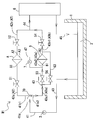
- FIG. 1 It is a schematic diagram which showed the whole structure of the filtration apparatus of this embodiment, and is a schematic diagram which showed the flow of lubricating oil at the time of normal filtration operation
- FIG. It is the model which showed the whole structure of the filtration apparatus of a prior art.
- FIG. 1 is a schematic view showing the entire configuration of the filtration device of the present embodiment, and is a schematic view showing the flow of lubricating oil in a normal filtration operation.
- the filtration device W1 of the present embodiment is used, for example, for filtering the lubricating oil 2 used for the device 6 mounted on a ship.
- the filtration device W1 sucks up the lubricating oil 2 from the storage tank 1 in which the dirty lubricating oil 2 used in the equipment 6 is stored and filters it to remove foreign matter, and the filtered lubricating oil 2 is removed from the equipment 6. It comes to supply.
- the equipment 6 is configured to discharge the lubricating oil 2 that has become dirty due to use in the storage tank 1. That is, in the present embodiment, the lubricating oil 2 circulates between the storage tank 1, the filtering device W1, and the device 6.
- the filtration device W1 is a pump (first pump) 3 for sucking up the lubricating oil (liquid) 2 stored in the storage tank 1 as in the filtration device W2 of the prior art. It has a backwashing type main filter A and a subfilter B installed parallel to the main filter A.
- the main filter A is a so-called backwash type filter, an inlet A1 into which the lubricating oil 2 flows, and a plurality of filtering elements (filter elements) which are filters such as a filter for filtering the lubricating oil 2 and a filtering element And a backwashing liquid outlet A3 for flowing back the backwashing liquid (backwashing oil) shown below.
- the main filter A is a part of the filtration elements (e.g., one filtration element) among the plurality of filtration elements (e.g., five filtration elements), and the other filtration elements (e.g., the remaining four filtration elements)
- the clean lubricating oil 2 filtered in the above flows in a direction opposite to the normal flow, and has a self-backwashing structure for cleaning the part of the filter element.
- the filter elements to be washed are sequentially replaced to wash each filter element.
- the filtration accuracy of the filtration element of the above-mentioned main filter A is appropriate, but for example, 25 to 50 ⁇ m is suitable, and more preferably 40 to 50 ⁇ m.
- said self-backwashing structure is a well-known technique, description of a concrete structure is abbreviate
- the sub-filter B provided in parallel with the main filter A is a filter element (filter element), which is an inlet B1 into which the lubricating oil 2 flows, a filter for filtering the lubricating oil 2, and a filter element And an outlet B2 from which the lubricating oil 2 flows out.
- the filter element of the secondary filter B is, for example, a disposable cartridge type that can be replaced.
- the filtration accuracy of the filtration element of the sub-filter B is appropriate, but for example, 5 to 20 ⁇ m is suitable, and more preferably 10 to 20 ⁇ m.
- a pipe (second pipe) 43 for flowing out from the sub-filter B for flowing out from the sub-filter B.
- the pipe 41 is connected to the pump 3 at one end, and is branched at a branch portion 41a provided in the middle to be divided into two paths (two pipes: a pipe 41b1 and a pipe 41b2), one of the two paths
- the end of the pipe 41b1 is connected to one end of the pipe 42
- the end of the pipe 41b2 forming the other of the two paths is connected to one end of the pipe 43.
- the other end of the pipe 42 and the other end of the pipe 43 are joined (joined), and the pipe (apparatus connection pipe) 44 connected to the device 6 is connected to the joining portion.
- the device 6 and the storage tank 1 are connected by a pipe (a pipe for discharge) 45.
- a main filter A is connected to the above-described pipe 42, and a first valve (on-off valve) 51 that controls the inflow and inflow stop of the lubricating oil 2 to the main filter A, and the main filter A fourth valve (opening / closing valve) 52 is provided to control the outflow and the outflow stop of the lubricating oil 2 (filtered lubricating oil 2) from A.
- the pipe 42 is "a pipe 42a whose one end is connected to the pipe 41b1 and whose other end is connected to the inlet A1 of the main filter A", and "an end A2 of the main filter A is an outlet A2 And the other end portion is constituted by a pipe 42 b ′ ′ connected to the pipe 44.
- bulb 51 is provided in the piping 42a
- bulb 52 is provided in the piping 42b.
- the first valve 51 and the fourth valve 52 are provided before and after the main filter A, respectively.
- a second filter (opening / closing valve) 53 is connected to the above-mentioned piping 43 and controls the inflow and the inflow stop of the lubricating oil 2 to the sub-filter B as well as the sub-filter B.
- a third valve (opening / closing valve) 54 is provided to control the outflow and the outflow stop of the lubricating oil 2 (filtered lubricating oil 2) from B.
- the pipe 43 is "a pipe 43a whose one end is connected to the pipe 41b2 and whose other end is connected to the inlet B1 of the subfilter B", and "an end B2 of the subfilter B is an outlet B2 And the other end portion is constituted by a pipe 43 b ′ ′ connected to the pipe 44.
- bulb 53 is provided in the piping 43a
- bulb 54 is provided in the piping 43b.
- the second valve 53 and the third valve 54 are provided on the front and back sides of the sub-filter B, respectively.
- the backwashing oil (lubricant oil 2 used in the self-backwashing washing) which flows out from the backwashing liquid outlet A3 of the main filter A, the second valve 53 and the subfilter B A pipe 47 (third pipe) is provided to flow between them (a pipe 47 for allowing the backwashing oil to flow into the sub-filter B).
- one end of the pipe 47 is connected to the backwash liquid outlet A3 of the main filter A, and the other end is connected to a portion between the second valve 53 and the sub-filter B in the pipe 43a. (Piping 43a2) is connected.
- Piping (fourth piping) 63 is provided. Specifically, one end of the pipe 63 is connected to "the portion (pipe 43b1) of the pipe 43b between the outlet B2 of the subfilter B and the third valve 54", and the other end is "the pipe 43a It is connected to a portion (pipe 43a1) between the one end portion (the connection portion with the pipe 41b2) and the second valve 53. Note that one end of the pipe 63 may be directly connected to the outlet B2 of the sub-filter B. Further, the pipe 63 is provided with a fifth valve (opening / closing valve) 56 that controls the outflow and the outflow stop of the lubricating oil 2 (filtered lubricating oil 2) from the sub-filter B.
- a fifth valve opening / closing valve
- the pipe 47 which allows the backwashing oil discharged from the backwashing liquid outlet A3 of the main filter A to flow between the second valve 53 and the subfilter B as described above is mainly used.
- a pump (second pump) 7 is provided which sucks up the backwashing oil of the filter A (lubricant oil 2 used in self-backwashing) and flows it into the subfilter B. Even when the oil pressure of the lubricating oil 2 sent from the storage tank 1 to the main filter A is low by providing the pump 7 or when the filter element of the sub-filter B is clogged, The lubricating oil 2 can flow out of the filter A into the sub-filter B.
- the pump 7 of this embodiment is driven during the “ordinary filtration operation”, and is used for backwashing oil discharged from the main filter A to the subfilter B (used in self-backwashing cleaning).
- the pressure of the lubricating oil 2) is set to suck back flow from the main filter A and to flow out to the sub-filter B so that the pressure of the lubricating oil 2) becomes higher than the pressure of the main filter A.
- an orifice 70 is provided in the other pipe 41b2 of the two pipes (the pipe 41b1 and the pipe 41b2) branched at the branch portion 41a in the pipe 41 described above.
- the orifice 70 is generally used as a flow control, but in the present embodiment, performs the function of pressure control. Specifically, the orifice 70 provided in the pipe 41b2 adjusts the pressure of the pipe 41 so that the pressure of the pipe 41b2 becomes higher than the pressure of the pipe 41b1 during the “ordinary filtration operation”. It is supposed to be.
- the backwashing oil filtered by the subfilter B (the lubricating oil 2 used in the self-backwashing washing) is the main filter A and the subfilter A Due to the pressure difference with the filter B, the main filter A comes to flow again through the path “Piping 63 ⁇ Piping 43a1 ⁇ Piping 41b2 ⁇ Piping 41b1 ⁇ Piping 42a”.
- the pipe (pipe 48 shown in FIG. 3) for causing backwash oil to flow out to the storage tank 1 becomes unnecessary, and the filtration device W1 and the storage tank The number of pipes between 1 and 1 can be reduced, and the filtration device W1 itself can be made compact.
- the filtration device W1 When performing a normal filtration operation, the filtration device W1 is set as follows. Specifically, the first valve 51, the fourth valve 52, and the fifth valve 56 are set in an open state (open state), and the second valve 53 and the third valve 54 are closed (closed state). Set Also, the pump 3 and the pump 7 are driven.
- the lubricating oil 2 stored in the storage tank 1 is sucked up by the drive of the pump 3, and the sucked lubricating oil 2 flows into the main filter A.
- the lubricating oil 2 stored in the storage tank 1 is sucked up from the storage tank 1 by the pump 3, flows into the pump 3 through the pipe 40, and flows into the pipe 41 through the pump 3, Then, it flows into the pipe 42a through the pipe 41b1, passes through the open first valve 51 provided in the pipe 42a, and flows (introduced) into the main filter A from the inlet A1 of the main filter A.
- the lubricating oil 2 flowing into the main filter A from the piping 42 is filtered by most of the filtration elements in the main filter A to remove foreign matter, and most of the filtered lubricating oil 2 is It flows out from the outlet A2 into the pipe 42b, flows through the fourth valve 52 in an open state provided in the pipe 42b, flows into the pipe 44, and is introduced into the device 6. Further, the lubricating oil 2 introduced into the device 6 is used in the device 6, and the lubricating oil 2 contaminated by the use is discharged from the device 6 through the pipe 45 to the storage tank 1.
- a part of the filtered lubricating oil 2 is flowed in a direction opposite to the normal direction to a part of the filter elements to be cleaned to wash the part of the filter elements And some filter elements are washed (backwashed).
- the lubricating oil 2 contaminated by this backwashing is sucked up by the pump 7 at a predetermined pressure, flows out from the backwashing liquid outlet A3 to the pipe 47, and is sent to the pipe 43a2 between the second valve 53 and the filter B.
- the backwashing oil (lubricating oil 2) flowing into the pipe 43a2 between the second valve 53 and the filter B is connected to the sub-filter from the pipe 43a2. It is introduced to B.
- the backwashing oil (lubricating oil 2) introduced into the subfilter B is filtered and cleaned in the subfilter B.
- the filtered lubricating oil 2 is discharged from the outlet B2 of the subfilter B into the pipe 43b1.
- the pressure of the filter B is higher than the pressure of the main filter A by the drive of the pump 7 and the function of adjusting the pressure of the orifice 70 provided in the pipe 41 b 2.
- the pressure of the pipe 41b2 is higher than the pressure of the pipe 41b1.
- pressure adjustment for setting the pressure of the filter B in a higher state compared to the pressure of the main filter A can be made particularly easy.
- the lubricating oil 2 (lubricant oil 2 filtered and cleaned by the filter B) that has flowed out to the pipe 43a1 is “a pipe 41b2 and a pipe 41b1 according to the pressure difference between the main filter A and the auxiliary filter B. Flow to the pipe 42 a through the “1.
- the pressure of the pipe 41b2 is higher than the pressure of the pipe 41b1 by the orifice 70, the lubricating oil 2 flowing into the pipe 41b2 from the pipe 43a1 (filtered and cleaned by the sub-filter B)
- the backwash oil (lubricating oil 2)) smoothly joins with the lubricating oil 2 which the pump 3 has sucked from the storage tank 1 at the branch portion 41a of the pipe 41.
- FIG. 2 is a schematic view showing the entire configuration of the filtration device of the present embodiment, and in the case of the filtration operation when the main filter is not used due to the occurrence of an emergency or the like in the main filter. It is a schematic diagram showing the flow of lubricating oil. In the case where the main filter A is not used, when an emergency situation occurs in the main filter A, when washing the main filter A, or when performing lubricating oil flushing at the initial operation of the device 6, Say the case.
- the filtration device W1 When performing a filtration operation without using the main filter A, the filtration device W1 is set as follows. Specifically, the first valve 51, the fourth valve 52, and the fifth valve 56 are closed (closed), and the second valve 53 and the third valve 54 are opened (open). Set Further, the pump 3 is brought into the driving state, and the pump 7 is brought into the stopping state.
- the lubricating oil 2 stored in the storage tank 1 by the drive of the pump 3 is sucked up from the storage tank 1, flows into the pump 3 through the pipe 40, flows into the pipe 41 through the pump 3, and thereafter , Flows into the pipe 43, passes through the second valve 53 in the open state, and flows (introduced) into the sub-filter B from the inlet B1 of the sub-filter B. Further, the lubricating oil 2 introduced into the sub-filter B is filtered by the sub-filter B and then discharged from the outlet B2 of the filter B into the pipe 43b1 between the filter B and the valve 54.
- the pump 7 is provided, and during normal filtration operation, the pump 7 sucks backwash oil (the lubricating oil 2 used in self-backwashing) from the main filter A and It is configured to flow into the filter B.
- the pressure of the sub-filter B can be made higher than that of the main filter A. Therefore, in the present embodiment, due to the pressure difference between the main filter A and the sub-filter B, the backwashing oil filtered by the subfilter B (the lubricating oil 2 used in the self-backwashing washing) is The main filter A can be made to flow again through the route of piping 43a1 ⁇ piping 41b2 ⁇ piping 41b1 ⁇ piping 42a.
- the pressure of the pipe 41b2 is higher than the pressure of the pipe 41b1 by the orifice 70 provided in the pipe 42b2. Therefore, at the time of the “normal filtration operation”, the lubricating oil 2 flowing from the pipe 43a1 to the pipe 41b2 at the branch portion 41a of the pipe 41 (a backwash oil filtered and cleaned by the sub-filter B (lubricating oil 2) and the lubricating oil 2 pumped up from the storage tank 1 by the pump 3 can be smoothly joined.
- the "pipe for causing backwash oil to flow out to the storage tank 1" as in the prior art described above is not necessary, and it is installed at a distant position inside a ship with limited space.
- the oil pressure of the lubricating oil 2 sent from the storage tank 1 to the main filter A is low by providing the pump 7 or when the filter element of the sub-filter B is clogged,
- the lubricating oil 2 can be discharged from the main filter A to the sub-filter B. That is, by providing the pump 7, it is possible to prevent the occurrence of the phenomenon that the backwashing oil 2 does not flow out to the sub-filter B and the backwashing of the main filter A can not be generated.
- the filtration device W1 having the backwash-type main filter A and the sub-filter B can reduce the number of pipes and miniaturize the device itself.
- the filtration device W1 capable of securing the flow of the backwash liquid can be provided.
- the present invention is not limited to the above embodiment, and various modifications can be made within the scope of the present invention.
- a liquid other than the lubricating oil 2 for example, a liquid such as fuel oil, seawater, wash water, cooling water.
Landscapes
- Chemical & Material Sciences (AREA)
- Engineering & Computer Science (AREA)
- Chemical Kinetics & Catalysis (AREA)
- Combustion & Propulsion (AREA)
- Mechanical Engineering (AREA)
- Ocean & Marine Engineering (AREA)
- Health & Medical Sciences (AREA)
- Environmental & Geological Engineering (AREA)
- General Health & Medical Sciences (AREA)
- Public Health (AREA)
- Toxicology (AREA)
- Filtration Of Liquid (AREA)
Abstract
Un dispositif de filtration W1 comprend un tube 42 pour permettre à un liquide 2 dans un réservoir de stockage 1 de s'écouler à l'intérieur et à l'extérieur d'un filtre principal de lavage à contre-courant A, un tube 43 pour amener le liquide 2 à s'écouler à l'intérieur et à l'extérieur d'un filtre secondaire B, et un tube 47 pour amener le liquide de lavage à contre-courant du filtre principal A à s'écouler dans le filtre secondaire B une première vanne 51 pour commander l'entrée et l'arrêt d'entrée du liquide dans le filtre principal A est fournie au tube 42. Une seconde vanne 53 pour commander l'entrée et l'arrêt d'entrée du liquide dans le filtre secondaire B est fournie au tube 43, comme étant une troisième vanne 54 pour commander l'arrêt d'écoulement et de sortie du liquide à partir du filtre secondaire B un tube 63 pour permettre au liquide qui s'est écoulé depuis le filtre secondaire B de s'écouler vers l'extérieur et à s'écouler dans le tube 42 est fourni à un tube 43b1. Une pompe 7 pour aspirer le liquide de lavage à contre-courant dans le filtre principal A et permettre à celle-ci de s'écouler dans le filtre secondaire B est fournie au tube 47.
Applications Claiming Priority (2)
| Application Number | Priority Date | Filing Date | Title |
|---|---|---|---|
| JP2017194078A JP6469198B1 (ja) | 2017-10-04 | 2017-10-04 | 濾過装置 |
| JP2017-194078 | 2017-10-04 |
Publications (1)
| Publication Number | Publication Date |
|---|---|
| WO2019069520A1 true WO2019069520A1 (fr) | 2019-04-11 |
Family
ID=65356100
Family Applications (1)
| Application Number | Title | Priority Date | Filing Date |
|---|---|---|---|
| PCT/JP2018/025886 Ceased WO2019069520A1 (fr) | 2017-10-04 | 2018-07-09 | Dispositif de filtration |
Country Status (2)
| Country | Link |
|---|---|
| JP (1) | JP6469198B1 (fr) |
| WO (1) | WO2019069520A1 (fr) |
Cited By (1)
| Publication number | Priority date | Publication date | Assignee | Title |
|---|---|---|---|---|
| CN112093021A (zh) * | 2020-08-19 | 2020-12-18 | 招商局邮轮制造有限公司 | 一种滑油净化兼污油驳运系统 |
Families Citing this family (2)
| Publication number | Priority date | Publication date | Assignee | Title |
|---|---|---|---|---|
| DE202020105401U1 (de) | 2020-09-21 | 2022-01-07 | Boll & Kirch Filterbau Gesellschaft mit beschränkter Haftung | Filtrationssystem für die Ölfiltration insbesondere für Schiffsaggregate wie Schiffsmotoren |
| JP7445144B2 (ja) * | 2021-09-21 | 2024-03-07 | 神奈川機器工業株式会社 | 濾過装置 |
Citations (7)
| Publication number | Priority date | Publication date | Assignee | Title |
|---|---|---|---|---|
| FR2036584A5 (fr) * | 1969-03-25 | 1970-12-24 | Moatti Georges | |
| JP2004057983A (ja) * | 2002-07-30 | 2004-02-26 | Fuji Photo Film Co Ltd | 濾過装置 |
| JP4225997B2 (ja) * | 2005-11-02 | 2009-02-18 | 神奈川機器工業株式会社 | 濾過装置 |
| JP2014036915A (ja) * | 2012-08-13 | 2014-02-27 | Kanagawa Kiki Kogyo Kk | フィルタエレメント及び当該フィルタエレメントを備えた逆洗型ろ過装置 |
| JP3189904U (ja) * | 2014-01-24 | 2014-04-03 | 株式会社コンヒラ | 濾過装置 |
| WO2016132308A1 (fr) * | 2015-02-18 | 2016-08-25 | Boll & Kirch Filterbau Gmbh | Système de filtration pour filtrer une huile lubrifiante, en particulier pour des unités marines telles que des moteurs marins |
| WO2017085643A1 (fr) * | 2015-11-16 | 2017-05-26 | Boll & Kirch Filterbau Gmbh | Circuit d'huile avec filtres, en particulier pour moteurs marins |
-
2017
- 2017-10-04 JP JP2017194078A patent/JP6469198B1/ja active Active
-
2018
- 2018-07-09 WO PCT/JP2018/025886 patent/WO2019069520A1/fr not_active Ceased
Patent Citations (7)
| Publication number | Priority date | Publication date | Assignee | Title |
|---|---|---|---|---|
| FR2036584A5 (fr) * | 1969-03-25 | 1970-12-24 | Moatti Georges | |
| JP2004057983A (ja) * | 2002-07-30 | 2004-02-26 | Fuji Photo Film Co Ltd | 濾過装置 |
| JP4225997B2 (ja) * | 2005-11-02 | 2009-02-18 | 神奈川機器工業株式会社 | 濾過装置 |
| JP2014036915A (ja) * | 2012-08-13 | 2014-02-27 | Kanagawa Kiki Kogyo Kk | フィルタエレメント及び当該フィルタエレメントを備えた逆洗型ろ過装置 |
| JP3189904U (ja) * | 2014-01-24 | 2014-04-03 | 株式会社コンヒラ | 濾過装置 |
| WO2016132308A1 (fr) * | 2015-02-18 | 2016-08-25 | Boll & Kirch Filterbau Gmbh | Système de filtration pour filtrer une huile lubrifiante, en particulier pour des unités marines telles que des moteurs marins |
| WO2017085643A1 (fr) * | 2015-11-16 | 2017-05-26 | Boll & Kirch Filterbau Gmbh | Circuit d'huile avec filtres, en particulier pour moteurs marins |
Cited By (1)
| Publication number | Priority date | Publication date | Assignee | Title |
|---|---|---|---|---|
| CN112093021A (zh) * | 2020-08-19 | 2020-12-18 | 招商局邮轮制造有限公司 | 一种滑油净化兼污油驳运系统 |
Also Published As
| Publication number | Publication date |
|---|---|
| JP6469198B1 (ja) | 2019-02-13 |
| JP2019063762A (ja) | 2019-04-25 |
Similar Documents
| Publication | Publication Date | Title |
|---|---|---|
| KR102469606B1 (ko) | 특히 선박 엔진과 같은 선박 기계를 위한 오일을 여과하기 위한 여과 시스템 | |
| JP5189549B2 (ja) | 逆洗浄機能付濾過システムおよび濾過器の洗浄方法 | |
| WO2019069520A1 (fr) | Dispositif de filtration | |
| TWI817219B (zh) | 船舶清掃裝置的過濾系統 | |
| KR102950798B1 (ko) | 정수기 | |
| KR102622548B1 (ko) | 수처리장치 | |
| JP2011183257A (ja) | 濾過装置 | |
| KR101064635B1 (ko) | 자체 세정 기능을 갖춘 필터 | |
| KR102614247B1 (ko) | 정수기 | |
| JP4225997B2 (ja) | 濾過装置 | |
| JP5280204B2 (ja) | 浄水装置の運転方法 | |
| CN108483520A (zh) | 交互清洗海水过滤装置 | |
| JP6388118B2 (ja) | 人工透析装置 | |
| CN107952271B (zh) | 连续自洗式过滤器 | |
| KR100792590B1 (ko) | 여과시스템 | |
| JP3189904U (ja) | 濾過装置 | |
| RU2017130640A (ru) | Система фильтрации воды | |
| JP5048140B2 (ja) | 浄水器 | |
| JP7445144B2 (ja) | 濾過装置 | |
| KR20210051018A (ko) | 정수기 | |
| JP2010155196A (ja) | 濾過装置 | |
| JP2010022940A (ja) | フィルタ洗浄装置 | |
| CN105523652B (zh) | 净水设备 | |
| KR20140071653A (ko) | 중력 발라스팅 장치 및 이를 이용한 필터 역세 방법 | |
| JP7596827B2 (ja) | ストレーナ設備 |
Legal Events
| Date | Code | Title | Description |
|---|---|---|---|
| 121 | Ep: the epo has been informed by wipo that ep was designated in this application |
Ref document number: 18864532 Country of ref document: EP Kind code of ref document: A1 |
|
| NENP | Non-entry into the national phase |
Ref country code: DE |
|
| 122 | Ep: pct application non-entry in european phase |
Ref document number: 18864532 Country of ref document: EP Kind code of ref document: A1 |