WO2019069953A1 - Corps optique - Google Patents
Corps optique Download PDFInfo
- Publication number
- WO2019069953A1 WO2019069953A1 PCT/JP2018/036948 JP2018036948W WO2019069953A1 WO 2019069953 A1 WO2019069953 A1 WO 2019069953A1 JP 2018036948 W JP2018036948 W JP 2018036948W WO 2019069953 A1 WO2019069953 A1 WO 2019069953A1
- Authority
- WO
- WIPO (PCT)
- Prior art keywords
- layer
- optical
- optical layer
- light
- master
- Prior art date
- Legal status (The legal status is an assumption and is not a legal conclusion. Google has not performed a legal analysis and makes no representation as to the accuracy of the status listed.)
- Ceased
Links
Images























Classifications
-
- B—PERFORMING OPERATIONS; TRANSPORTING
- B32—LAYERED PRODUCTS
- B32B—LAYERED PRODUCTS, i.e. PRODUCTS BUILT-UP OF STRATA OF FLAT OR NON-FLAT, e.g. CELLULAR OR HONEYCOMB, FORM
- B32B3/00—Layered products comprising a layer with external or internal discontinuities or unevennesses, or a layer of non-planar shape; Layered products comprising a layer having particular features of form
- B32B3/26—Layered products comprising a layer with external or internal discontinuities or unevennesses, or a layer of non-planar shape; Layered products comprising a layer having particular features of form characterised by a particular shape of the outline of the cross-section of a continuous layer; characterised by a layer with cavities or internal voids ; characterised by an apertured layer
- B32B3/30—Layered products comprising a layer with external or internal discontinuities or unevennesses, or a layer of non-planar shape; Layered products comprising a layer having particular features of form characterised by a particular shape of the outline of the cross-section of a continuous layer; characterised by a layer with cavities or internal voids ; characterised by an apertured layer characterised by a layer formed with recesses or projections, e.g. hollows, grooves, protuberances, ribs
-
- B—PERFORMING OPERATIONS; TRANSPORTING
- B32—LAYERED PRODUCTS
- B32B—LAYERED PRODUCTS, i.e. PRODUCTS BUILT-UP OF STRATA OF FLAT OR NON-FLAT, e.g. CELLULAR OR HONEYCOMB, FORM
- B32B7/00—Layered products characterised by the relation between layers; Layered products characterised by the relative orientation of features between layers, or by the relative values of a measurable parameter between layers, i.e. products comprising layers having different physical, chemical or physicochemical properties; Layered products characterised by the interconnection of layers
- B32B7/02—Physical, chemical or physicochemical properties
-
- E—FIXED CONSTRUCTIONS
- E06—DOORS, WINDOWS, SHUTTERS, OR ROLLER BLINDS IN GENERAL; LADDERS
- E06B—FIXED OR MOVABLE CLOSURES FOR OPENINGS IN BUILDINGS, VEHICLES, FENCES OR LIKE ENCLOSURES IN GENERAL, e.g. DOORS, WINDOWS, BLINDS, GATES
- E06B9/00—Screening or protective devices for wall or similar openings, with or without operating or securing mechanisms; Closures of similar construction
- E06B9/24—Screens or other constructions affording protection against light, especially against sunshine; Similar screens for privacy or appearance; Slat blinds
-
- G—PHYSICS
- G02—OPTICS
- G02B—OPTICAL ELEMENTS, SYSTEMS OR APPARATUS
- G02B5/00—Optical elements other than lenses
-
- G—PHYSICS
- G02—OPTICS
- G02B—OPTICAL ELEMENTS, SYSTEMS OR APPARATUS
- G02B5/00—Optical elements other than lenses
- G02B5/02—Diffusing elements; Afocal elements
-
- G—PHYSICS
- G02—OPTICS
- G02B—OPTICAL ELEMENTS, SYSTEMS OR APPARATUS
- G02B5/00—Optical elements other than lenses
- G02B5/20—Filters
- G02B5/28—Interference filters
Definitions
- the present invention relates to an optical body.
- Patent Document 1 discloses, as an optical film having the above configuration, a first base material having a concavo-convex surface in which a plurality of prisms are one-dimensionally arranged, a laminated film formed on the concavo-convex surface, and this laminated film A retroreflective polarizer is disclosed comprising a second substrate formed thereon.
- one example of such a concavo-convex shape of an optical film is that a plurality of columnar convex portions extended in one direction are one-dimensionally arrayed in one direction.
- the shape is Here, the heights of the columnar projections are the same at any position, and the distance between the apexes of adjacent projections is the same at any position.
- the optical film having the above-mentioned shape is disposed on a window glass, for example, as a heat ray reflective film for retroreflecting sunlight so that the one-dimensionally arranged direction is parallel to the horizontal direction.
- a window glass for example, as a heat ray reflective film for retroreflecting sunlight so that the one-dimensionally arranged direction is parallel to the horizontal direction.
- light inserted from the sun, for example, incident from above on the southeast is reflected upward to the southwest.
- This reflected light reflects the heat ray in the case of the function of heat ray retroreflection, because the sunlight serving as the light source is locally reflected. If a building exists in the direction in which the reflected light travels straight, it will receive heat rays and will suffer from heat damage.
- the reflected light is visible light, the user may feel glare, and the view from the window may be impaired. Therefore, at present, it is required to reduce local strong reflection in specular reflection in an optical body.
- the present invention is to reduce local strong reflection in specular reflection in an optical body having a convex shape in which a plurality of columnar convex portions extended in one direction are one-dimensionally arranged in one direction. It aims to provide an optical body that can
- the means for solving the problems are as follows. That is, ⁇ 1> A first optical layer having a convex shaped surface in which a plurality of columnar convex portions extended in one direction are one-dimensionally arranged in one direction; An inorganic layer disposed on the surface on the side having the convex shape of the first optical layer; A second optical layer disposed on the inorganic layer side so as to bury the convex shape; Have The optical body is characterized in that the convex shape satisfies at least one of the following (1) to (4). (1) The height of each columnar protrusion changes in the extending direction.
- each columnar convex portion the apex meanders in a direction orthogonal to both the extending direction and the height direction of the convex portion. (3) The heights of adjacent columnar projections are different. (4) The triangular prism-shaped convex portion and the columnar convex portion having a curved surface are adjacent to each other.
- ⁇ 2> The optical body according to ⁇ 1>, wherein the inorganic layer is a wavelength selective reflection layer.
- ⁇ 3> The optical body according to ⁇ 1>, wherein the inorganic layer is semipermeable.
- ⁇ 4> The optical body according to any one of ⁇ 1> to ⁇ 3>, wherein the first optical layer and the second optical layer have transparency.
- ⁇ 5> The optical body according to any one of ⁇ 1> to ⁇ 4>, which is used by being attached to a window glass.
- an optical body having a convex shape in which a plurality of columnar convex portions extended in one direction are one-dimensionally arranged in one direction local strong reflection in specular reflection is reduced. It is possible to provide an optical body that can
- FIG. 1A is a diagram for explaining a state where sunlight is reflected to a window to which an optical film having a heat ray retroreflective structure shown in FIG. 3A is attached (part 1).
- FIG. 1B is a view for explaining a state where sunlight is reflected to a window to which an optical film having a heat ray retroreflective structure shown in FIG. 3A is attached (part 2).
- FIG. 2A is a diagram for explaining a state where sunlight is reflected to a window to which an optical film having a heat ray retroreflective structure shown in FIG. 4A is attached (part 1).
- FIG. 2B is a view for explaining a state where sunlight is reflected to the window to which the optical film having the heat ray retroreflective structure shown in FIG.
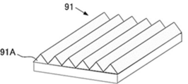
- FIG. 3A is a perspective view of a first optical layer in a conventional example.
- FIG. 3B is a top view of the first optical layer in the conventional example.
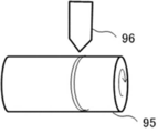
- FIG. 3C is a schematic view of a master and a cutting tool for manufacturing the first optical layer of FIGS. 3A and 3B.
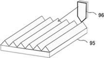
- FIG. 3D is a perspective view of the original disc of FIG. 3C in the form of a flat plate.
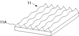
- FIG. 4A is a perspective view of an example of the first optical layer of the optical body of the present invention.
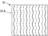
- FIG. 4B is a top view of an example of the first optical layer of the optical body of the present invention.
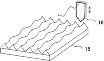
- FIG. 4C is a schematic view of a master and a cutting tool for manufacturing the first optical layer of FIGS.
- FIG. 4D is a perspective view of the original disc of FIG. 4C in the form of a flat plate.
- FIG. 5A is a perspective view of another example of the first optical layer of the optical body of the present invention.
- FIG. 5B is a top view of another example of the first optical layer of the optical body of the present invention.
- FIG. 5C is a schematic view of a master and a cutting tool for manufacturing the first optical layer of FIGS. 5A and 5B.
- FIG. 5D is a perspective view of the original disc of FIG. 5C in a flat plate shape.
- FIG. 6A is a perspective view of another example of the first optical layer of the optical body of the present invention.
- FIG. 6A is a perspective view of another example of the first optical layer of the optical body of the present invention.
- FIG. 6B is a top view of another example of the first optical layer of the optical body of the present invention.
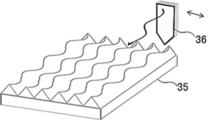
- FIG. 6C is a schematic view of a master and a cutting tool for producing the first optical layer of FIGS. 6A and 6B.
- FIG. 6D is a perspective view of the original disc of FIG. 6C in the form of a flat plate.
- FIG. 7A is a perspective view of another example of the first optical layer of the optical body of the present invention.
- FIG. 7B is a top view of another example of the first optical layer of the optical body of the present invention.
- FIG. 7C is a schematic view of a master and a cutting tool for manufacturing the first optical layer of FIGS. 7A and 7B.
- FIG. 7D is a perspective view of the original disc of FIG.
- FIG. 8A is a perspective view of another example of the first optical layer of the optical body of the present invention.
- FIG. 8B is a top view of another example of the first optical layer of the optical body of the present invention.
- FIG. 8C is a schematic view of a master and a cutting tool for manufacturing the first optical layer of FIGS. 8A and 8B.
- FIG. 8D is a perspective view of the original disc of FIG. 8C in a flat plate shape.
- FIG. 9A is a perspective view of another example of the first optical layer of the optical body of the present invention.
- FIG. 9B is a top view of another example of the first optical layer of the optical body of the present invention.
- FIG. 9A is a perspective view of another example of the first optical layer of the optical body of the present invention.
- FIG. 9B is a top view of another example of the first optical layer of the optical body of the present invention.
- FIG. 9C is a schematic view of a master and a cutting tool for producing the first optical layer of FIGS. 9A and 9B.
- FIG. 9D is a perspective view of the original disc of FIG. 9C in a flat plate shape.
- FIG. 10A is a cross-sectional view for explaining the height of the convex portion of the first optical layer (part 1).
- FIG. 10B is a cross-sectional view for explaining the height of the convex portion of the first optical layer (part 2).
- FIG. 11A is a cross-sectional view for explaining the distance (pitch) of adjacent convex portions in the first optical layer (part 1).
- FIG. 11B is a cross-sectional view for explaining the distance (pitch) of adjacent convex portions in the first optical layer (part 2).
- FIG. 10A is a cross-sectional view for explaining the distance (pitch) of adjacent convex portions in the first optical layer (part 1).
- FIG. 11B is a cross-sectional view for explaining
- FIG. 12 is a cross-sectional view of an example of the optical body of the present invention.
- FIG. 13A is a cross-sectional view for explaining an example of the function of the optical body of the present invention.
- FIG. 13B is a cross-sectional view for explaining an example of the function of the optical body of the present invention.
- FIG. 14 is a perspective view showing the relationship between incident light incident on an optical body having wavelength selective reflectivity and reflected light reflected by the optical body.
- FIG. 15A is a process diagram for describing an example of a method of manufacturing an optical body according to an embodiment of the present invention (part 1).
- FIG. 15: B is process drawing for demonstrating an example of the manufacturing method of the optical body which concerns on one Embodiment of this invention (the 2).
- FIG. 15A is a process diagram for describing an example of a method of manufacturing an optical body according to an embodiment of the present invention (part 1).
- FIG. 15: B is process drawing for demonstrating an example of the manufacturing method of the optical
- FIG. 15C is a process diagram for describing an example of a method of manufacturing an optical body according to an embodiment of the present invention (part 3).
- FIG. 16A is a process diagram for describing an example of a method of manufacturing an optical body according to an embodiment of the present invention (part 4).
- FIG. 16B is a process diagram for describing an example of a method of manufacturing an optical body according to an embodiment of the present invention (part 5).
- FIG. 16C is a process diagram for describing an example of a method of manufacturing an optical body according to an embodiment of the present invention (part 6).
- FIG. 17A is a process diagram for describing an example of a method of manufacturing an optical body according to an embodiment of the present invention (part 7).
- FIG. 17B is a process diagram for describing an example of a method of manufacturing an optical body according to an embodiment of the present invention (part 8).
- FIG. 17C is a process diagram for describing an example of a method of manufacturing an optical body according to an embodiment of the present invention (part 9).
- FIG. 18A is a diagram for describing an average height (AH), an amplitude (A), a period (Pe), and an inclination angle (E) which is the maximum variation.
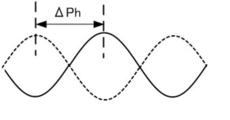
- FIG. 18B is a diagram for explaining the shift ( ⁇ Ph) of the periodic change.
- FIG. 19 is a diagram for explaining an amplitude (Ab), a period (Peb), an inclination angle (Eb) which is a maximum change amount, and a shift ( ⁇ Phb) of a periodic change.
- FIG. 20 is a graph showing the relationship between the amplitude and the relative value of the reflected light intensity.
- FIG. 21 is a graph showing the relationship between the amplitude / period and the relative value of the reflected light intensity.
- FIG. 22 is a graph showing the relationship between the maximum change angle and the relative value of the reflected light intensity.
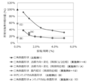
- FIG. 23 is a graph showing the relationship between the amplitude and the relative value of the upper reflection component.
- FIG. 24 is a graph showing the relationship between the amplitude / period and the relative value of the upper reflection component.
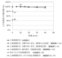
- FIG. 25 is a graph showing the relationship between the maximum change angle and the relative value of the upper reflection component.
- FIG. 26 is a view showing a state in which the optical body is bonded to float glass using
- the optical body of the present invention has at least a first optical layer, an inorganic layer, and a second optical layer, and further has other members as required.
- a conventional optical film 100A having a convex shape in which a plurality of columnar convex portions extended in one direction are one-dimensionally arranged in one direction is horizontally aligned in a direction in which the one-dimensional arrangement is made on the window glass.
- Light arranged from the sun 101 to the window 100 is usually specularly reflected, and a columnar array extending in one direction at the place where the light is inserted into the window 100. It is reflected to the sky side with the direction axis as the axis (FIGS. 1A and 1B). In such cases, the sunlight is locally reflected (FIGS. 1A and 1B).
- the building 102 will be exposed to the reflected light. Therefore, when the heat rays are reflected, the reflected heat rays are applied to the part where the sunlight does not penetrate originally or the place where the sunlight is incident in the building 102, and the heat damage is caused. It will be received (FIG. 1A).
- a convex shape in which a plurality of columnar convex portions extended in one direction are one-dimensionally arranged in one direction in the optical body Disturbing the elasticity, specifically, a convex shape in which a plurality of columnar convex portions extended in one direction in the optical body are one-dimensionally arranged in one direction is the following (1) to By finding out at least one of (4), it has been found that local strong reflection of specular reflection can be reduced, and the present invention has been accomplished. (1) The height of each columnar protrusion changes in the extending direction.
- each columnar convex portion the apex meanders in a direction orthogonal to both the extending direction and the height direction of the convex portion. (3) The heights of adjacent columnar projections are different. (4) The triangular prism-shaped convex portion and the columnar convex portion having a curved surface are adjacent to each other.
- the convex shape in which a plurality of columnar convex portions extended in one direction are one-dimensionally arranged in one direction, and the convex shape satisfies at least one of the above (1) to (4)
- the optical film 100B of the present invention is disposed on the window glass so that the one-dimensionally arranged direction is parallel to the horizontal direction, the light inserted from the sun 101 to the window 100 is the light to the window 100 At the inserted portion, the light is reflected to the sky side with the columnar arrangement direction extending in one direction as an axis (FIGS. 2A and 2B). In such a case, the sunlight is usually strongly reflected locally (FIGS. 1A and 1B).
- the optical film 100B of the present invention when used, local specular reflection is alleviated (FIGS. 2A and 2B). Therefore, even when there is an adjacent building 102, the building 102 is less susceptible to heat damage.
- FIG. 3A is a perspective view of the first optical layer 91 in the conventional example.
- FIG. 3B is a top view of the first optical layer 91 in the conventional example.
- a plurality of columnar convex portions 91A extended in one direction are one-dimensionally arranged in one direction.
- a thick linear solid line indicates the top of the column-shaped convex portion 91A, and a broken line indicates a valley bottom between the column-shaped convex portion.
- the heights of the columnar projections 91A are the same at any position, and the distance between the tops of the adjacent projections. Is the same at any position.
- the first optical layer 91 of FIGS. 3A and 3B is produced, for example, as follows.
- the first optical layer 91 is produced by transferring the convex shape of the master on which the convex shape is formed.
- the master 95 is, for example, in a roll shape. While rotating the master 95, the master 95 is scraped by applying a cutting tool 96 having a tip portion of a predetermined shape to the master 95 so as to cut a predetermined depth.
- FIG. 3D is a perspective view of the master 95 in a flat plate shape.
- a cutting tool 96 having a tip of a predetermined shape is applied to the master 95 so as to cut a predetermined depth to cut the master 95 in a spiral shape.
- the master plate 95 is pressed against the uncured resin sheet, or the uncured resin sheet is pressed against the master plate 95, the convex shape of the master plate 95 is transferred to the resin sheet, and the resin sheet is cured. Can be obtained.
- FIGS. 4A and 4B a plurality of columnar convex portions 11A extended in one direction are one-dimensionally arranged in one direction.
- a thick linear solid line indicates the top of the columnar convex portion 11A
- a broken line indicates a valley bottom between the columnar convex portions.
- the heights of the columnar protrusions 11A are continuously changed.
- the top and the bottom are both linear.
- the first optical layer 11 is produced by transferring the convex shape of the master on which the convex shape is formed.
- the master 15 is, for example, in a roll shape. While rotating the master 15, the master 15 is cut by applying a cutting tool 16 having a tip portion of a predetermined shape to the master 15. By giving vertical movement to the cutting tool 16 at the time of cutting, cutting grooves having continuously different cutting depths can be obtained.
- the cutting tool 16 is moved in a direction perpendicular to the rotation direction by a predetermined distance, and cutting of the master 15 is restarted.
- FIG. 4D is a perspective view of the master 15 in the form of a flat plate.
- the vertical movement of the cutting tool 16 can be performed, for example, by using drive means such as a piezo element or a solenoid actuator.
- the master 15 is pressed against the uncured resin sheet, or the uncured resin sheet is pressed against the master 15, the convex shape of the master 15 is transferred to the resin sheet, and the resin sheet is cured.
- the optical layer 11 can be obtained.
- a mold (replica) having a reverse shape to which the convex shape of the master 15 is transferred is manufactured, and the mold is pressed against the uncured resin sheet.
- the first optical layer 11 can also be obtained by copying the convex shape to the resin sheet and curing the resin sheet.
- FIGS. 5A and 5B a plurality of columnar convex portions 21A extended in one direction are one-dimensionally arranged in one direction.
- a thick wavy solid line indicates the top of the columnar protrusion 21A
- a broken line indicates a valley bottom between the columnar protrusions.
- the heights of the columnar protrusions 21A are continuously changed.
- the peak is meandering and the valley bottom is linear.
- the first optical layer 21 is produced by transferring the convex shape of the master on which the convex shape is formed.
- the master 25 is, for example, in a roll shape. While rotating the master 25, the master 25 is cut by applying a cutting tool 26 having a tip portion of a predetermined shape to the master 25. By giving vertical movement to the cutting tool 26 at the time of cutting, cutting grooves having continuously different cutting depths can be obtained.
- the cutting tool 26 is moved in a direction perpendicular to the rotation direction by a predetermined distance, and cutting of the master 25 is resumed.
- FIG. 5D is a perspective view of the master 25 in the form of a flat plate.
- the cutting tool 26 while rotating the roll-shaped original disc 25, the cutting tool 26 having a tip portion of a predetermined shape is applied to the original disc 25 so as to cut a predetermined depth to cut the original disc 25 in a spiral shape.
- the cutting groove as shown in FIG. 5D is obtained by giving vertical movement to the cutting tool 26 while shifting the timing so that the cutting depth is not always the same depth in the direction orthogonal to the rotation direction of the master 25. Is obtained.
- a mold (replica) having a reverse shape to which the convex shape of the master 25 is transferred is manufactured, and the convex shape of the master 25 is copied to the resin sheet by pressing the mold against an uncured resin sheet, By curing the resin sheet, the first optical layer 21 can be obtained.
- the original disc 25 is pressed against the uncured resin sheet, or the uncured resin sheet is pressed against the original disc 25, the convex shape of the original disc 25 is transferred to the resin sheet, and the resin sheet is cured.
- the first optical layer 21 can also be obtained.
- the top view of the first optical layer 21 is in a state in which the solid line and the broken line are interchanged in FIG. 5B. That is, the tops of the columnar projections are on a straight line when viewed from the top, and the valley bottoms between the pillars are serpentine and wavy when viewed from the top.
- a plurality of columnar convex portions 31A extended in one direction are one-dimensionally arranged in one direction.
- a thick wavy solid line indicates the top of the column-shaped convex portion 31A
- a broken line indicates a valley bottom between the column-shaped convex portions.
- the heights of the columnar projections 31A are the same, but the apexes of the columnar projections 31A extend in the same direction. It is meandering in the direction orthogonal to the height direction.
- the first optical layer 31 of FIGS. 6A and 6B is produced, for example, as follows.
- the first optical layer 31 is produced by transferring the convex shape of the master on which the convex shape is formed.
- the master 35 is, for example, in a roll shape. While rotating the master 35, the master 35 is cut by applying a cutting tool 36 having a tip portion of a predetermined shape to the master 35. By cutting the cutting tool 36 horizontally horizontally during cutting, a meandering cutting groove can be obtained without changing the cutting depth.
- the cutting tool 36 When cutting for one turn of the master 35 is completed, the cutting tool 36 is moved in a direction perpendicular to the rotation direction by a predetermined distance, and cutting of the master 35 is restarted.
- the timing of the lateral movement is the same timing as before. That is, the timing of the lateral movement is made the same so that the plurality of cutting grooves generated by cutting meander in the same shape from the cutting start to the cutting end.
- 6D is a perspective view of the original plate 35 in the form of a flat plate.
- the master 35 is pressed against the uncured resin sheet, or the uncured resin sheet is pressed against the master 35, the convex shape of the master 35 is transferred to the resin sheet, and the resin sheet is cured.
- the optical layer 31 can be obtained.
- a mold (replica) having a reverse shape to which the convex shape of the master plate 35 is transferred is manufactured, and the die is pressed against the uncured resin sheet.
- the first optical layer 31 can be obtained by copying the convex shape to the resin sheet and curing the resin sheet.
- the plurality of columnar convex portions 41A extended in one direction are one-dimensionally arranged in one direction.
- a thick wavy solid line indicates the top of the columnar convex portion 41A
- a broken line indicates a valley bottom between the columnar convex portions.
- the heights of the columnar projections 41A are the same, but the apexes of the columnar projections 41A extend in the first optical layer 41. It is meandering in the direction orthogonal to the height direction.
- the first optical layer 41 of FIGS. 7A and 7B is produced, for example, as follows.
- the first optical layer 41 is produced by transferring the convex shape of the master on which the convex shape is formed.
- the master 45 is, for example, in a roll shape. While rotating the master 45, the master 45 is scraped by applying a cutting tool 46 having a tip portion of a predetermined shape to the master 45. During the cutting, by making the cutting tool 46 perform a pendulum movement with the tip as an axis, the cutting tip has a straight and meandering cutting groove.
- the cutting tool 46 is moved by a predetermined distance in the direction orthogonal to the rotation direction, and cutting of the master 45 is restarted.
- the timing of the pendulum movement is the same timing as before. That is, the timing of the pendulum movement is made the same so that the plurality of cutting grooves generated by cutting meander in the same shape from the cutting start to the cutting end.
- FIG. 7D is a perspective view of the master 45 in the form of a flat plate.
- a mold (replica) having a reverse shape to which the convex shape of the master 45 is transferred is manufactured, and the convex shape of the master 45 is copied to the resin sheet by pressing the mold against an uncured resin sheet,
- the first optical layer 41 can be obtained by curing the resin sheet.
- a plurality of columnar convex portions 51A extending in one direction are one-dimensionally arranged in one direction.
- a thick linear solid line indicates the top of the columnar convex portion 51A
- a broken line indicates a valley bottom between the columnar convex portions.
- the heights of adjacent columnar convex portions 51A are different.
- the top and the bottom are both linear.
- the first optical layer 51 is produced by transferring the convex shape of the master on which the convex shape is formed.
- the master 55 is, for example, in a roll shape. While rotating the master 55, a cutter 56 having a tip portion 56A of a predetermined shape is applied to the master 55 to cut the master 55.
- the master 55 is used with a cutting tool 56 having a tip portion 56B having a tip shape different from that of the tip portion 56A from a position moved by a predetermined distance in a direction orthogonal to the rotation direction. Resume cutting.
- FIG. 8D is a perspective view of the master 55 in the form of a flat plate.
- the first optical layer 51 can be obtained by pressing the master 55 against an uncured resin sheet and transferring the convex shape of the master 55 onto the resin sheet to cure the resin sheet.
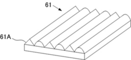
- a plurality of columnar convex portions 61A extended in one direction are one-dimensionally arranged in one direction.
- a thick linear solid line indicates the apex of the triangular prismatic convex portion
- a thick linear dashed dotted line indicates the apex of the columnar convex portion having a curved surface
- a broken line indicates a valley bottom between the columnar convexities.
- the triangular prism-shaped convex portion and the columnar convex portion having a curved surface are adjacent to each other.
- the first optical layer 61 of FIGS. 9A and 9B is produced, for example, as follows.
- the first optical layer 61 is produced by transferring the convex shape of the master on which the convex shape is formed.
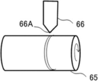
- the master 65 is, for example, in a roll shape. While rotating the master 65, a cutter 66 having a predetermined triangular tip 66A is applied to the master 65 to cut the master 65.
- FIG. 9D is a perspective view of the original plate 65 in the form of a flat plate.
- a mold (replica) having a reverse shape to which the convex shape of the master 65 is transferred is manufactured, and the convex shape of the master 65 is copied to the resin sheet by pressing the mold against an uncured resin sheet,
- the first optical layer 61 can be obtained by curing the resin sheet.
- the first optical layer has a convex-shaped surface in which a plurality of columnar projections extending in one direction are one-dimensionally arranged in one direction.
- the first optical layer supports and protects the inorganic layer formed on the uneven surface.
- the first optical layer has a convex shape as described above. That is, the convex shape satisfies at least one of the following (1) to (4).
- (1) The height of each columnar protrusion changes in the extending direction.
- the apex meanders in a direction orthogonal to both the extending direction and the height direction of the convex portion.
- the heights of adjacent columnar projections are different.
- the triangular prism-shaped convex portion and the columnar convex portion having a curved surface are adjacent to each other.
- the average height of the protrusions in the first optical layer is not particularly limited and may be appropriately selected according to the purpose, but is preferably 5 ⁇ m to 1,000 ⁇ m, and more preferably 10 ⁇ m to 300 ⁇ m. 20 ⁇ m to 100 ⁇ m are particularly preferred.
- the height will be described with reference to the drawings.
- 10A and 10B are schematic cross-sectional views of the first optical layer in the direction orthogonal to the direction in which the plurality of convex portions are one-dimensionally arranged. In the height (H), as shown in FIGS.
- the bottom (B) of the convex portion corresponds to an imaginary line connecting two valleys sandwiching the convex portion. Then, in the perpendicular from the top of the convex portion to the plane of the first optical layer 71, the distance from the top of the convex portion to the intersection of the perpendicular and the bottom (B) of the convex portion is the height (H). .
- the average value of the distance (pitch) between the plurality of convex portions in the first optical layer is not particularly limited and may be appropriately selected according to the purpose, but it is preferably 10 ⁇ m to 3,000 ⁇ m, and 20 ⁇ m. -900 ⁇ m is more preferable, 40 ⁇ m to 300 ⁇ m is still more preferable, and 45 ⁇ m to 90 ⁇ m is particularly preferable.
- the distance (pitch) will be described with reference to the drawings.
- 11A and 11B are schematic cross-sectional views of the first optical layer in the direction orthogonal to the direction in which the plurality of convex portions are one-dimensionally arranged.
- the distance (pitch) (P) is, as shown in FIGS.
- the distance (pitch) (P) means a perpendicular (L 1 ) from the top of one convex portion to the plane of the first optical layer 71.
- the distance from the top of another protrusion adjacent to the one protrusion to the perpendicular (L r ) to the plane of the first optical layer 71 is indicated.
- the height and the distance can be determined, for example, by observing an electron micrograph of a cross-sectional view.
- the average value can be determined by arbitrarily measuring 50 points of the convex shape satisfying at least one of the above (1) to (4).
- the shape of the convex portion is, for example, triangular in a cross section orthogonal to the extending direction.
- the average height (AH) of each columnar convex portion may be, for example, 15 ⁇ m to 45 ⁇ m, or 25 ⁇ m to 35 ⁇ m.
- the change in height of the convex portion of each column is periodic, and the period (Pe) in the change may be, for example, 400 ⁇ m to 1,200 ⁇ m. , 600 ⁇ m to 1,000 ⁇ m, or 700 ⁇ m to 900 ⁇ m.
- the change in height of the convex portion of each column is periodic, and the amplitude (A) in the change is 5 ⁇ m to 5 from the viewpoint of reducing local reflection of upward reflection. 65 ⁇ m is preferred.
- the amplitude (A) is more preferably 5 ⁇ m to 40 ⁇ m, particularly preferably 10 ⁇ m to 30 ⁇ m, considering the processability of the master production and the inflow of the resin component to the master. .
- the ratio of the amplitude (A) to the period (Pe) [amplitude ( ⁇ m) / period ( ⁇ m)] is preferably 0.6% to 7.8%, From the viewpoint of reduction of local reflection of upward reflection and processability, 0.6% to 5.0% is more preferable, and 1.2% to 3.8% is particularly preferable.
- the change range of the amplitude for example, a sine wave or a curve with a wavelike curve with a gradually increasing curvature such as a cycloid curve, an involute curve, or a combination of sine waves of higher harmonics and a curve with a combination thereof
- the inclination angle (E) which is the maximum change amount at that time be in the range of 1.1 deg to 13.7 deg. If the angle range is further increased, the cutting edge is cut larger than the cutting angle when cutting in the cutting edge of the cutting edge, which is undesirable because the cutting edge may be damaged after processing.
- 1.1 deg to 13.7 deg is preferable, 1.1 deg to 9.9 deg is more preferable, and 2.2 deg to 6.7 deg is particularly preferable.
- a deviation ( ⁇ Ph) of periodic change of the heights of the adjacent columnar convex portions a quarter period to a 3/4 period is preferable, and a 1/3 period to a 2/3 period is more preferable, and 2 It is further more preferable to use a / 5 period to a 3/5 period, and a 1/2 period is particularly preferable.
- FIG. 18A is a view for explaining the average height (AH), the amplitude (A), the period (Pe), the inclination angle (E) which is the maximum change amount.
- This figure is a cross-sectional view of the columnar convex portion as viewed from the extending direction and the direction orthogonal to the thickness direction.
- the average height (AH) is an average value from the bottom of the convex portion to the height of the convex portion.
- the amplitude (A) is the difference between the highest and lowest heights of the changing height.
- the period (Pe) is a period of varying height.
- the inclination angle (E) which is the maximum change amount is a derivative value of the change in height at the position where the change in height is maximum.
- difference ((DELTA) Ph) of a periodic change to FIG. 18B is shown.
- a solid curve is a ridge line of the first columnar convex portion, and a broken curve is a ridge line of a second columnar convex portion adjacent to the first columnar convex portion.
- the shift of the periodic change ( ⁇ Ph) is the shift of the periodic change of the heights of two adjacent pillar-shaped convex portions.
- the shift of the periodic change ( ⁇ Ph) is a half cycle.
- the average height of each columnar convex portion may be, for example, 15 ⁇ m to 45 ⁇ m, or 25 ⁇ m to 35 ⁇ m.
- the meandering is periodic, and the meandering period (Peb) may be, for example, 400 ⁇ m to 1,200 ⁇ m, or 600 ⁇ m to 1,000 ⁇ m. It may be 700 ⁇ m to 900 ⁇ m.
- the meandering amplitude (Ab) is preferably 5 ⁇ m to 65 ⁇ m from the viewpoint of reduction of local reflection of upward reflection.
- the amplitude (Ab) is more preferably 5 ⁇ m to 40 ⁇ m, particularly preferably 10 ⁇ m to 30 ⁇ m, considering the processability of the master production and the inflow of the resin component to the master.
- the ratio (amplitude / period) of the amplitude (Ab) to the period (Peb) is preferably 0.6% to 7.8%.
- the change range of the meander for example, a sine wave, or a curve with a wavelike curve with a gradually increasing curvature such as a cycloid curve, an involute curve, or a sine wave combination of higher harmonics, and a curve with a combination thereof
- the inclination angle (Eb) which is the maximum change amount at that time be in the range of 1.1 deg to 13.7 deg. If the angle range is further increased, it is not preferable because the cutting edge is damaged after machining because it is larger than the cutting angle when cutting and cutting the cutting edge of the cutting edge.
- 1.1 deg to 13.7 deg is preferable, 1.1 deg to 9.9 deg is more preferable, and 1.1 deg to 6.7 deg is particularly preferable.
- the deviation ( ⁇ Phb) of the periodic change of the meandering of the adjacent columnar convex portions 1/4 period to 3/4 period is preferable, 1/3 period to 2/3 period is more preferable, and 2 / Still more preferably 5 cycles to 3/5 cycles, and particularly preferably 1/2 cycle.
- the amplitude (Ab), the period (Peb), the inclination angle (Eb) as the maximum change amount, and the deviation of the periodic change ( ⁇ Phb) will be described with reference to the drawings.
- FIG. 19 is a diagram for explaining the amplitude (Ab), the period (Peb), the inclination angle (Eb) as the maximum amount of change, and the shift of the periodic change ( ⁇ Phb).
- This figure is a top view of the columnar convex portion as viewed from above.
- a solid curve is a ridge line of a columnar convex portion, and an alternate long and short dash line indicates a valley bottom between two convex portions.
- the amplitude (Ab) is the width of the meander.
- the period (Peb) is a period in periodic meandering.
- the inclination angle (Eb) which is the maximum change amount is a differential value of the change of the meander at the position where the change of the meander is the maximum.
- the shift of the periodic change ( ⁇ Phb) is a half cycle.
- the absolute value of the difference in height between adjacent columnar convex portions is, for example, preferably 5 ⁇ m to 65 ⁇ m, more preferably 5 ⁇ m to 40 ⁇ m, and particularly preferably 5 ⁇ m to 30 ⁇ m.
- the change in height in (1), the meandering in (2), the difference in height in (3), and the arrangement of the triangular prismatic convex portions in (4) and the columnar convex portions having a curved surface Preferably periodic.
- the reason is as follows. It is also possible to arrange at random about change of a structure (convex part). However, as a result of arranging at random, when the large size of the height of the structure and the small size of the height of the structure are successively arranged, the structure having a height once Before the light reflected by the light strikes the structure that is reflected again by the structure with height, the absorptance may be increased by transmitting a long distance through the resin of the transparent body. There is a possibility to reduce the efficiency.
- the entire one surface of the first optical layer may have the predetermined convex shape, or a portion of the one surface of the first optical layer may have the predetermined convex shape. You may have. In the case where a portion of one surface of the first optical layer has the predetermined convex shape, it is preferable to have the predetermined convex shape at a portion where local strong reflection in specular reflection is desired to be reduced.
- the optical body of the present invention an aspect in which only a convex shape which is one-dimensionally arranged is present on one surface of the first optical layer has been mentioned, but as another aspect of the optical body of the present invention
- one surface of the first optical layer is configured by a two-dimensional array in which two one-dimensional arrays are combined.
- the two-dimensional array is configured by combining two one-dimensional arrays.
- the two-dimensional array is a two-dimensional array in which one one-dimensional array of convex shapes and another one-dimensional array of convex shapes having different directions of extension and different angles are combined. In this case, at least one of the following (1) to (4) described above is satisfied in one or both of the one-dimensionally arranged convex shapes.
- each columnar protrusion changes in the extending direction.
- the apex meanders in a direction orthogonal to both the extending direction and the height direction of the convex portion.
- the heights of adjacent columnar projections are different.
- the triangular prism-shaped convex portion and the columnar convex portion having a curved surface are adjacent to each other.
- retroreflection is realized by reflecting on the reflecting surface three times, but in the corner cube, absorption of solar radiation is more likely to occur due to multiple reflection, but only the one-dimensional array or the two-dimensional arrangement
- the number of reflections is reduced, and the solar radiation absorption can be suppressed.
- retroreflection is realized by reflecting on the reflecting surface three times, but in the corner cube body, part of the light leaks in a direction other than the retroreflection due to reflection twice.
- a shape that reflects more towards the sky In the case of only a one-dimensional array, or in the case of the two-dimensional array, it is possible to have a shape that reflects more towards the sky.
- the first optical layer has a characteristic of absorbing light of a specific wavelength in the visible region in a range that does not impair the transparency to visible light, from the viewpoint of providing design properties to an optical member, window material, etc. May be
- the design property can be imparted, that is, the property of absorbing light of a specific wavelength in the visible region can be achieved, for example, by incorporating a pigment in the first optical layer.
- the pigment is preferably dispersed in a resin.
- the pigment to be dispersed in the resin is not particularly limited and may be appropriately selected according to the purpose. Examples thereof include inorganic pigments and organic pigments, and in particular, inorganic pigments having high weather resistance. It is preferable to use as a pigment.
- the inorganic pigment is not particularly limited and may be appropriately selected depending on the purpose, for example, zircon gray (Co, Ni-doped ZrSiO 4), praseodymium yellow (Pr-doped ZrSiO 4), chromium titanium yellow (Cr Sb-doped TiO 2 or Cr, W-doped TiO 2 ), chromium green (such as Cr 2 O 3 ), peacock ((CoZn) O (AlCr) 2 O 3 ), Victoria green ((Al, Cr) 2 O 3 ) Bitumen (CoO ⁇ Al 2 O 3 ⁇ SiO 2 ), vanadium zirconium blue (V-doped ZrSiO 4 ), chromium tin pink (Cr-doped CaO ⁇ SnO 2 ⁇ SiO 2 ), porcelain red (Mn-doped Al 2 O 3 ), salmon pink (Fe-doped ZrSiO 4) and the like.
- zircon gray
- the material of the first optical layer include resins such as thermoplastic resins, active energy ray curable resins, and thermosetting resins.
- the first optical layer has, for example, transparency.
- the first optical layer is obtained, for example, by curing a resin composition. From the viewpoint of easiness of production, it is preferable to use, as the resin composition, an energy ray-curable resin that cures with light or an electron beam, or a thermosetting resin that cures with heat.
- the energy ray-curable resin a photosensitive resin composition which is cured by light is preferable, and an ultraviolet-curable resin composition which is cured by ultraviolet light is most preferable.
- the resin composition further contains a compound containing phosphoric acid, a compound containing succinic acid, and a compound containing butyrolactone from the viewpoint of improving the adhesion between the first optical layer and the inorganic layer.
- a compound containing phosphoric acid for example, (meth) acrylate containing phosphoric acid, preferably a (meth) acrylic monomer or oligomer having phosphoric acid as a functional group can be used.
- the compound containing succinic acid for example, (meth) acrylate containing succinic acid, preferably (meth) acrylic monomer or oligomer having succinic acid as a functional group can be used.
- a (meth) acrylate containing butyrolactone for example, a (meth) acrylate containing butyrolactone, preferably a (meth) acrylic monomer or oligomer having butyrolactone as a functional group can be used.
- the ultraviolet curable resin composition contains, for example, (meth) acrylate and a photopolymerization initiator.
- the UV curable resin composition may further contain a light stabilizer, a flame retardant, a leveling agent, an antioxidant, and the like, as necessary.
- the monomer and / or oligomer which have a 2 or more (meth) acryloyl group.
- this monomer and / or oligomer for example, urethane (meth) acrylate, epoxy (meth) acrylate, polyester (meth) acrylate, polyol (meth) acrylate, polyether (meth) acrylate, melamine (meth) acrylate and the like are used be able to.
- a (meth) acryloyl group means either an acryloyl group or a methacryloyl group.
- an oligomer means a molecule having a molecular weight of 500 or more and 60000 or less.
- Examples of polyfunctional monomers that can be used for the ultraviolet curable resin composition include ethanediol diacrylate, 1,3-propanediol diacrylate, 1,4-butanediol diacrylate, and 1,6-hexanediol diacrylate.
- the photopolymerization initiator one appropriately selected from known materials can be used.
- known materials for example, benzophenone derivatives, acetophenone derivatives, anthraquinone derivatives and the like can be used alone or in combination.
- the compounding quantity of the said polymerization initiator is 0.1 mass% or more and 10 mass% or less in solid content. If the amount is less than 0.1% by mass, the photocurability may be reduced, and it may not be practically suitable for industrial production. On the other hand, when it exceeds 10% by mass, an odor tends to remain in the coating film when the amount of irradiation light is small.
- solid content means all the components which comprise the hard-coat layer after hardening. Specifically, for example, (meth) acrylate, a photopolymerization initiator and the like are referred to as solid content.
- the inorganic layer is a layer disposed on the surface on the side having the convex shape of the first optical layer.
- a reflective layer that reflects at least near infrared rays is preferable.
- the following laminated film etc. are mentioned, for example. Details of an example of the reflective layer will be described later.
- an average film thickness of the said inorganic layer there is no restriction
- the average film thickness is 20 ⁇ m or less, the optical path along which the transmitted light is refracted becomes short, and the transmitted image can be prevented from appearing distorted.
- a sputtering method for example, a vapor deposition method, a dip coating method, the die coating method etc. can be used.
- the inorganic layer is, for example, semipermeable.
- semi-transmissive means that the transmittance at a wavelength of 500 nm to 1,000 nm is 5% to 70%, preferably 10% to 60%, and more preferably 15% to 55%.
- the semi-transmissive layer refers to a reflective layer having a transmittance of 5% to 70%, preferably 10% to 60%, and more preferably 15% to 55% at a wavelength of 500 nm to 1,000 nm. .
- Laminated film There is no restriction
- a metal having high reflectance in the infrared region is used.
- the metal having a high reflectance in the infrared region is not particularly limited and can be appropriately selected according to the purpose.
- Au, Ag, Cu, Al, Ni, Cr, Ti, Pd, Co, Si examples thereof include simple substances such as Ta, W, Mo and Ge, and alloys containing two or more of these simple substances.
- Ag-based, Cu-based, Al-based, Si-based and Ge-based are preferable in terms of practicality.
- the alloy is not particularly limited and may be appropriately selected according to the purpose.
- the optically transparent layer is an optically transparent layer having a high refractive index in the visible region and functioning as an antireflective layer.
- the optically transparent layer there is no restriction
- a thin buffer layer of Ti or the like having a thickness of about several nm may be provided on the interface of the optically transparent layer to be formed for the purpose of preventing the oxidation degradation of the lower layer metal during the formation of the optically transparent layer.
- the buffer layer is a layer for suppressing oxidation of a metal layer or the like which is a lower layer by oxidizing itself when forming the upper layer.
- the transparent conductive layer is a transparent conductive layer mainly composed of a conductive material having transparency in the visible region.
- a transparent conductive layer mainly composed of a conductive material having transparency in the visible region.
- a transparent conductive layer mainly composed of a conductive material having transparency in the visible region.
- transparent conductive layer there is no restriction
- nanoparticles of the transparent conductive substance nanoparticles of conductive materials such as metal, nanorods, and a layer in which nanowires are dispersed in a resin at a high concentration may be used.
- the functional layer is a layer containing as a main component a chromic material whose reflection performance and the like are reversibly changed by an external stimulus.
- the chromic material is, for example, a material that reversibly changes its structure by external stimuli such as heat, light, and penetration molecules.
- limiting in particular as said chromic material According to the objective, it can select suitably, For example, a photochromic material, a thermochromic material, a gas chromic material, an electrochromic material, etc. are mentioned.
- the photochromic material is a material that reversibly changes its structure by the action of light.
- the photochromic material is a material capable of reversibly changing physical properties such as reflectance and color by irradiation with light such as ultraviolet light.
- the photochromic material is not particularly limited and may be appropriately selected depending on the purpose, for example, Cr, Fe, TiO 2 doped with like Ni, WO 3, MoO 3, Nb 2 O 5 transition metal such as An oxide etc. can be mentioned.
- wavelength selectivity can also be improved by laminating
- thermochromic material is a material that reversibly changes its structure by the action of heat.
- the thermochromic material can reversibly change various physical properties such as reflectance and color by heating.
- the thermochromic material is not particularly limited and may be appropriately selected depending on the purpose, for example, VO 2, and the like.
- elements such as W, Mo and F can be added for the purpose of controlling the transition temperature and transition curve.
- a thin film whose main component is a thermochromic material such as VO 2 may be sandwiched by an antireflective layer whose main component is a high refractive index material such as TiO 2 or ITO.
- photonic lattices such as cholesteric liquid crystals can also be used.
- the cholesteric liquid crystal can selectively reflect light of a wavelength according to the layer spacing, and the layer spacing changes with temperature, so that heating can reversibly change physical properties such as reflectance and color. it can. At this time, it is also possible to widen the reflection band by using several cholesteric liquid crystal layers having different layer intervals.
- the electrochromic material is a material capable of reversibly changing various physical properties such as reflectance and color by electricity.
- the electrochromic material for example, a material whose structure is reversibly changed by application of a voltage can be used.
- the reflection type light control material in which a reflection characteristic changes, etc. by doping or de-doping such as proton etc. is mentioned Be
- the reflection type light control material is a material whose optical property can be controlled to a transparent state, a mirror state, and / or an intermediate state thereof by an external stimulus.
- the reflection type light modulating material is not particularly limited and may be appropriately selected depending on the purpose, for example, alloy materials, WO 3 to alloy magnesium and nickel, an alloy material of magnesium and titanium as main components And materials in which needle crystals having selective reflectivity are confined in microcapsules.
- the catalyst layer which contains the said alloy layer, Pd, etc. on the 2nd optical layer Thin buffer layer such as Al, electrolyte layer such as Ta 2 O 5 , ion storage layer such as WO 3 containing proton, and transparent conductive layer, (ii) transparent conductive layer on second optical layer,
- transparent conductive layer on second optical layer examples thereof include an electrolyte layer, an electrochromic layer such as WO 3 and a configuration in which a transparent conductive layer is laminated. In these configurations, protons contained in the electrolyte layer are doped or de-doped in the alloy layer by applying a voltage between the transparent conductive layer and the counter electrode.
- the transmittance of the alloy layer is changed. Furthermore, in order to enhance wavelength selectivity, it is desirable to laminate the electrochromic material with a high refractive index material such as TiO 2 or ITO. Moreover, as another structure, the structure where the transparent conductive layer, the optically transparent layer which disperse
- the semipermeable layer is made of, for example, a single layer or a plurality of metal layers and is semipermeable. There is no restriction
- the second optical layer is a layer disposed on the inorganic layer side so as to bury the convex shape.
- the second optical layer protects, for example, the inorganic layer.
- Examples of the material of the second optical layer include the materials exemplified in the description of the first optical layer.
- one surface is a smooth surface
- the other surface is a concave shape.
- the convex shape of the first optical layer and the concave shape of the second optical layer are in a relationship in which unevenness is reversed.
- the optical body is, for example, an optical film.
- the optical body has transparency. It is preferable that it is what has the range of the transmitted image definition mentioned later as transparency.
- the difference in refractive index between the first optical layer and the second optical layer is preferably 0.010 or less, more preferably 0.008 or less, and still more preferably 0.005 or less. When the refractive index difference exceeds 0.010, the transmission image tends to appear blurred. If the refractive index difference is in the range of more than 0.008 and 0.010 or less, it also depends on the outside brightness, but there is no problem in daily life. When the refractive index difference is in the range of more than 0.005 and 0.008 or less, only a very bright object such as a light source is concerned with the diffraction pattern, but the outside scene can be clearly seen.
- an optical layer on the side to be attached to a window material or the like may have an adhesive as a main component.
- the optical body can be bonded to the window material or the like by the first optical layer or the second optical layer containing an adhesive material as a main component.
- the refractive index difference of an adhesive agent exists in the said range.
- the first optical layer and the second optical layer have the same optical characteristics such as refractive index. More specifically, it is preferable that the first optical layer and the second optical layer be made of the same material having transparency in the visible region. By making the first optical layer and the second optical layer of the same material, the refractive indices of the two become equal, and thus the transparency of visible light can be improved. However, even if the same material is used as a starting source, the refractive index of the finally formed layer may differ depending on the curing conditions in the film forming process, so care must be taken.
- the refractive index of the two is different, so that light is transmitted with the inorganic layer (for example, the wavelength selective reflection layer) as a boundary.
- the inorganic layer for example, the wavelength selective reflection layer
- an additive may be mixed in the first optical layer and / or the second optical layer.
- the first optical layer and the second optical layer preferably have transparency in the visible region.
- the definition of transparency has two meanings, that is, there is no absorption of light and no scattering of light. In general, only the former may be referred to when it is said to be transparent, but in the optical body it is preferable to have both.
- the retroreflectors currently in use are intended to visually recognize the display reflected light such as road signs and clothes of night workers, so for example, even if they have scattering properties, they are in close contact with the base reflector and If so, the reflected light can be viewed. For example, even if antiglare processing having scattering property is performed on the front surface of the image display device for the purpose of imparting antiglare property, the image is the same principle as visible.
- one embodiment of the optical body is characterized in that it transmits light other than a specific wavelength that is directed and reflected, and adheres to a transmitting body that mainly transmits this transmitting wavelength, and the transmitted light is In order to observe, it is preferable that there is no scattering of light. However, depending on the application, it is also possible to intentionally give the second optical layer scattering properties.
- the optical body is preferably bonded to a rigid body (for example, a window material) mainly permeable to light having a wavelength other than the transmitted specific wavelength through an adhesive or the like.
- a window material include window materials for construction such as high-rise buildings and houses, window materials for vehicles, and the like.
- the optical body is applied to an architectural window material, it is preferable to apply the optical film to a window material disposed in any direction (for example, south-east to south-west direction), in particular, from east to south to west. It is because a heat ray can be reflected more effectively by applying to the window material of such a position.
- the optical body can be used not only for window glass of a single layer but also for special glass such as double glazing.
- window material is not limited to what consists of glass, You may use what consists of a polymeric material which has transparency. It is preferred that the optical layer have transparency in the visible region. By thus having transparency, when the optical body is bonded to a window material such as a window glass, visible light can be transmitted, and it is possible to secure daylighting by sunlight. Moreover, as a surface to bond together, it can be used not only on the inner surface of glass but also on the outer surface.
- the optical body can be used in combination with other heat ray-cutting films, and for example, a light absorbing coating can be provided on the interface between air and the optical body (that is, the outermost surface of the optical body).
- the optical body can be used in combination with a hard coat layer, an ultraviolet ray cut layer, a surface antireflective layer, and the like.
- these functional layers it is preferable to provide these functional layers at the interface between the optical body and air.
- the ultraviolet cut layer since it is necessary to arrange the ultraviolet cut layer closer to the sun side than the optical body, it is used between the window glass surface and the optical body particularly when used as an inner pasting on the indoor window glass surface. It is desirable to provide a UV cut layer.
- an ultraviolet absorber may be kneaded into the bonding layer between the window glass surface and the body.
- the optical body may be colored to provide design.
- FIG. 12 is a cross-sectional view of an example of the optical body according to the first embodiment of the present invention.
- the optical body of FIG. 12 has the first optical layer 11 shown in FIGS. 4A and 4B.
- the optical body 10 includes a first optical layer 11 having a convex surface, and an inorganic layer 12 disposed on the surface of the first optical layer 11 on the side having the convex shape.
- the second optical layer 13 disposed so as to bury the convex shape on the inorganic layer 12 side, and the first disposed on the surface opposite to the surface having the convex shape of the first optical layer 11 And a substrate 14.
- ⁇ Wavelength selective reflectivity> 13A and 13B are cross-sectional views for explaining an example of the function of the optical body.
- the shape of the convex portion is a prism shape with an inclination angle of 45 °
- FIG. 13A a part of the light L 1 reflected in the sky of sunlight incident on the optical member 10 with respect to direct reflected incident direction about the same sky direction, the sky The unreflected light L 2 passes through the optical body 10.
- light L that is incident on the optical body 10 and reflected by the reflection film surface of the inorganic layer 12 (wavelength selective reflection layer) is light L that is reflected at a ratio according to the incident angle.
- FIG. 14 is a perspective view showing the relationship between incident light incident on the optical body 10 having wavelength selective reflectivity and reflected light reflected by the optical body 10.
- the optical body 10 has an incident surface S1 on which the light L is incident.
- the optical member 10 the angle of incidence (theta, phi) among the light L incident on the incident surface S1, selectively specular (- ⁇ , ⁇ + 180 °) directionally reflected in a direction other than the light L 1 in a specific wavelength band relative to, for transmitting light L 2 other than the specific wavelength band.
- the optical body 10 has transparency with respect to light other than the said specific wavelength range. It is preferable that it is what has the range of the transmitted image definition mentioned later as transparency.
- theta the perpendicular l 1 with respect to the incident surface S1, it is an angle formed between the incident light L or the reflected light L 1 (hereinafter sometimes referred to as "theta" and vertical angle).
- phi a specific linearly l 2 within the incident surface S1, the incident light L or the reflected light L 1 which is the angle between the projection ingredients on the incident surface S1 (hereinafter sometimes referred to as the azimuth angle "phi" ).
- the angle of incidence (theta, phi) is fixed to, when rotating the optical member 10 as an axis a perpendicular l 1 with respect to the incident surface S1 of the optical body 10, phi It is the axis where the reflection intensity in the direction is maximum. However, if the reflection intensity is more axial (direction) of maximum shall select one of them as linear l 2.
- the angle ⁇ rotated clockwise with respect to the perpendicular line 11 is defined as “+ ⁇ ”
- the angle ⁇ rotated counterclockwise is defined as “ ⁇ ”.
- the angle ⁇ rotated clockwise on the basis of the straight line 12 is set as “+ ⁇ ”
- the angle ⁇ rotated counterclockwise is set as “ ⁇ ”.
- the light of a specific wavelength band that is selectively directed and reflected and the specific light to be transmitted differ depending on the application of the optical body 10.
- light of a specific wavelength band that is selectively directed and reflected is near infrared light
- light of a specific wavelength band to be transmitted is visible.
- it is light.
- light of a specific wavelength band that is selectively directed and reflected is mainly near infrared light of a wavelength band of 780 nm or more and 2100 nm or less.
- directional reflection means that the reflected light intensity in a specific direction other than the specular reflection is stronger than the specular reflected light intensity and sufficiently stronger than the non-directive diffuse reflection intensity.
- “reflecting” indicates that the reflectance in a specific wavelength band, for example, the near infrared region, is preferably 30% or more, more preferably 50% or more, and still more preferably 80% or more.
- Transmission means that the transmittance in a specific wavelength band, for example, the visible light region, is preferably 30% or more, more preferably 50% or more, and still more preferably 70% or more.
- the direction ⁇ o of directional reflection is ⁇ 90 ° or more and 90 ° or less.
- the optical body 10 in this range is useful when there is no tall building in the vicinity.
- the direction of directional reflection be in the vicinity of ( ⁇ , ⁇ ).
- the term “nearby” means a deviation within a range of preferably 5 degrees, more preferably 3 degrees, and even more preferably 2 degrees from ( ⁇ , ⁇ ).
- the optical body 10 when the optical body 10 is attached to an external support, light of a specific wavelength band among the light incident from above the buildings standing at the same height is efficiently taken above the other buildings It is because it can be returned.
- a three-dimensional structure such as a part of a spherical surface or a hyperboloid, a triangular pyramid, a quadrangular pyramid, or a cone.
- Light incident from the ( ⁇ , ⁇ ) direction ( ⁇ 90 ° ⁇ ⁇ 90 °) is ( ⁇ o, ⁇ o) direction (0 ° ⁇ o ⁇ 90 °, ⁇ 90 ° ⁇ o ⁇ 90 °) based on its shape. Can be reflected).
- the optical body 10 having wavelength selective reflectivity directional reflection of light of a specific wavelength band is light of a specific wavelength band with respect to light incident on the incident surface S1 at a direction near retroreflection, that is, incident angle ( ⁇ , ⁇ ) It is preferable that the reflection direction of is near (.theta., .Phi.).
- the optical body 10 is attached to the external support, it is possible to return the light of the specific wavelength band among the light incident from the upper sky to the upper sky.
- the vicinity is preferably 5 degrees or less, more preferably 3 degrees or less, and still more preferably 2 degrees or less.
- the retroreflecting direction must be the same as the incident direction, but it is not necessary to sense from a specific direction Need not be in exactly the same direction.
- the value when using an optical comb of 2.0 mm is not particularly limited and can be appropriately selected according to the purpose. 60% or more is preferable and 75% or more is more preferable.
- the value when using an optical comb of 0.5 mm is not particularly limited, and can be appropriately selected according to the purpose. Is preferably 60% or more, more preferably 75% or more. If the transmitted image definition has a value of 60% or more and less than 75%, only a very bright object such as a light source is concerned with the diffraction pattern, but the outside scene can be clearly seen.
- the transmitted image definition has a value of 75% or more, the diffraction pattern is hardly noticeable.
- the value of the transmitted image sharpness is measured according to JIS K-7374: 2007 using ICM-1T manufactured by Suga Test Instruments.
- measurement is preferably performed after calibration using a filter of the wavelength to be transmitted.
- FIGS. 15A to 15C, 16A to 16C, and 17A to 17D ⁇ Method of manufacturing optical body>
- a part or all of the manufacturing process shown below is performed by roll-to-roll in consideration of productivity.
- the manufacturing process of the mold shall be excluded.
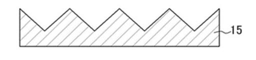
- the production example here is a production example of an optical body having the first optical layer 11 shown in FIGS. 4A and 4B.
- a mold replica
- Form The method of manufacturing the master 15 is as described with reference to FIGS. 4C and 4D.
- the convex shape of the master 15 is transferred to a film-like resin material using, for example, a melt extrusion method or a transfer method.
- a transfer method a method of pouring a photocurable resin composition into a mold and irradiating it with energy rays to cure it, a method of applying heat and pressure to a resin, transferring a shape, or supplying a resin film from a roll And the method of transferring the shape of the mold while adding (laminate transfer method).
- the 1st optical layer 11 which has convex shape in one main surface is formed.
- the first optical layer 11 may be formed on the first base material 14.
- the film-like first base material 14 is supplied from a roll, and after the photocurable resin composition is applied on the first base material 14, it is pressed against the mold to form the shape of the mold.
- a method of transferring and irradiating energy rays such as ultraviolet rays to cure the photocurable resin composition is used.
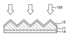
- a wavelength selective reflection layer (functional layer) as the inorganic layer 12 is formed on one principal surface of the first optical layer 11.
- a film-forming method of the wavelength-selective reflection layer as the inorganic layer 12 According to the objective, it can select suitably, For example, sputtering method, a vapor deposition method, CVD (Chemical Vapor Deposition) method, dip coating A method, a die coating method, a wet coating method, a spray coating method, etc. may be mentioned, and it is preferable to appropriately select from these film forming methods according to the shape of the convex shape and the like.
- an annealing process 150 is performed on the wavelength selective reflection layer as the inorganic layer 12 as necessary.
- the temperature of the annealing process is, for example, in the range of 100 ° C. or more and 250 ° C. or less.
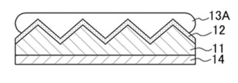
- the photocurable resin composition 13A is applied on the wavelength selective reflection layer as the inorganic layer 12.
- the laminate is formed by spreading the photocurable resin composition 13A to a predetermined thickness with a coater or the like to fill the convex shape.
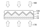
- the photocurable resin composition 13A is cured by, for example, energy rays 160, and a pressure 170 is applied to the laminate.
- energy ray there is no restriction
- the accumulated irradiation dose is not particularly limited, and can be appropriately selected in consideration of the curing characteristics of the resin, the suppression of yellowing of the resin and the first base material 14, and the like.
- the 2nd optical layer 13 is formed on the wavelength selection reflection layer as the inorganic layer 12, and the optical body 10 is obtained. Furthermore, in the optical body of the present invention, the second base may be disposed on the side opposite to the inorganic layer 12 side of the second optical layer 13. The flatness of the surface of the second optical layer 13 on the opposite side to the inorganic layer 12 is caused by the flatness of the coater head or the like, and the thickness of the resin (the degree of filling of the unevenness).
- Example 1 The effect was confirmed by simulation about the upper reflective directivity at the time of changing convex shape in an optical body.
- Example 1 the evaluation was performed on an optical body [optical body satisfying the above (1)] in which the height of the triangular cross section in the convex shape changes continuously in the extending direction.
- the convex shape has the following features. ⁇ Average pitch (distance between valleys of adjacent structures): 67 ⁇ m ⁇ Average height (AH): 31 ⁇ m ⁇ Height amplitude (A): 5 ⁇ m Amplitude type: Sine wave Sine wave period (Pe): 800 ⁇ m ⁇ Maximum inclination angle at top of extension direction (E): 1.1 deg ⁇ Difference with adjacent structure (phase) ( ⁇ Ph): 1/2 period
- simulation was performed by the ray tracing method.
- the light beam As the light beam, as a quasi-parallel light, a sufficient number of light beams were irradiated from the light source toward the reflective surface by the Monte Carlo method (the structure of the reflector embedded the resin with the resin in the same manner as the real thing).
- the upper infrared reflectance of near infrared rays at an angle ( ⁇ ) perpendicular to 20 deg from the direction normal to the surface of the measurement sample was calculated.
- the intensity of the light intensity at each vertical angle and azimuth angle of 1 deg was calculated similarly to the Mini Diff used for actual measurement described later, and the following comparison was made.
- Example 1 The convex shape of Example 1 is shown in Table 1-1.
- the evaluation results of Example 1 are shown in Table 1-2.
- the state of local reflection was evaluated by the following evaluation criteria.
- Light is reflected in a non-linear fashion from the part, and the bright spots are relaxed in a band or multiple by reducing the local bright spots
- Example 2 to 13 and Comparative Examples 1 and 2 In Example 1, evaluation was performed in the same manner as in Example 1 except that the shape of the convex portion was changed as shown in Table 1-1. The results are shown in Table 1-2.
- Example 13 In addition, in the convex shape of Example 13, as shown to FIG. 9A, the triangular-prism convex part and the columnar convex part which has a curved surface adjoin.
- FIG. 20 is a graph showing the relationship between the amplitude and the relative value of the reflected light intensity (local reflection intensity ratio).
- FIG. 21 is a graph showing the relationship between the amplitude / period and the relative value of the reflected light intensity (local reflection intensity ratio).
- FIG. 22 is a graph showing the relationship between the maximum change angle and the relative value of the reflected light intensity (local reflection intensity ratio).
- FIG. 23 is a graph showing the relationship between the amplitude and the relative value of the upper reflection component.
- FIG. 24 is a graph showing the relationship between the amplitude / period and the relative value of the upper reflection component.
- FIG. 25 is a graph showing the relationship between the maximum change angle and the relative value of the upper reflection component.
- Comparative Example 2 having only the curved surface shape has low upper reflection, and by combining the triangular prism of Example 13 and the curved surface shape, it is possible to suppress local reflection while having upper reflection. .
- the curved surface shape of Comparative Example 2 it is considered that the multiple reflections necessary for going upward are not performed.
- Example 14-1 ⁇ Preparation of Optical Body>
- the optical body to be produced is an optical body satisfying the above (1).
- an inorganic layer having the following structure for reflecting near infrared rays was formed by vacuum sputtering.
- a photocurable resin composition (resin refractive index 1.52 after curing) is applied on the formed inorganic layer, and ultraviolet rays are irradiated and cured on a PET base material (manufactured by Toray Industries, Inc., thickness 75 um).
- the second optical layer was formed.
- an optical body was obtained.
- the thickness of the obtained cured optical body was 205 ⁇ m.
- the obtained optical body was subjected to the following test and measurement. The results are shown in Table 2-2.
- the deposition of Al 2 O 3 -ZnO, ceramic target with the addition of Al 2 O 3 2 wt% of ZnO using [ZnO:: Al 2 O 3 100 2 ( weight ratio)], Nb 2 the formation of the O 5 using the Nb 2 O 5.
- the thickness of each layer indicates the thickness when forming a film on a flat surface having no shape.
- Reflective directivity was measured by MiniDiff manufactured by Light Tec, and the suppression effect of local reflection was evaluated. Since MiniDiff manufactured by Light Tec is an evaluation machine using a visible light source, it is difficult to measure the reflection distribution of near-infrared light. Therefore, the inorganic layer that reflects near-infrared light in Example 14-1 was changed to a film of Ag 30 nm. In addition, the size of the float glass having a thickness of 3 mm used for the above-described optical measurement was changed to 10 cm ⁇ 10 cm. Otherwise, samples were prepared in the same manner and used for measurement. This method makes it possible to measure the reflection distribution using visible light and to evaluate the reflection directivity.
- the upper reflectance of near infrared light at an angle ( ⁇ ) perpendicular to 20 deg from the direction normal to the surface of the measurement sample was measured.
- the direction of rotation was ⁇ 15 deg.
- the highest intensity value (peak reflection intensity) excluding specular reflection is read, and the highest intensity value (peak reflection intensity) excluding specular reflection of a triangular prism of Comparative Example 3-1 described later
- the relative value% when the result was 100% was calculated as the local reflection intensity ratio.
- the effect of suppressing local reflection was evaluated by the relative value of the highest intensity numerical value excluding specular reflection.
- ⁇ State of local reflection> The state of the distribution of the reflected light obtained when the reflection directivity was measured by the MiniDiff manufactured by Light Tec described above was evaluated according to the following evaluation criteria.
- ⁇ Evaluation of appearance of bright line The optical body was attached to a 15 cm ⁇ 15 cm float glass having a thickness of 3 mm via an adhesive material, and a small light source was irradiated from the upper 15 cm of the optical body to observe the appearance. The visibility of the bright line was evaluated according to the following evaluation criteria. ⁇ Evaluation criteria ⁇ X: A bright bright line is observed from the bright spot of the light source to the edge of the float glass-Good: The bright line becomes very thin from the bright spot of the light source to the edge of the float glass
- Example 14-2 to 14-15 In the evaluation of the local reflection, evaluation was performed in the same manner as in Example 14-1, except that the vertical direction angle ( ⁇ ) and the azimuth angle ( ⁇ ) were as shown in Table 2-2. The results are shown in Table 2-2.
- Example 15-1 An optical body was prepared in the same manner as in Example 14-1 except that the master processing specification was changed as follows in Example 14-1, and was evaluated in the same manner as in Example 14-1. The results are shown in Table 2-2.
- ⁇ Mastering specifications Average shape spacing (distance between valleys of adjacent structures): 67 ⁇ m Average shape height (AH): 31 ⁇ m Cross section base angle-D1: 35 deg Cross-section base angle-D2: 55 deg Height amplitude in the extension direction (A): 21 ⁇ m Height modulation in the extension direction: Sine wave Period of sine wave (Pe): 800 ⁇ m Shift (phase) with adjacent structure ( ⁇ Ph): 1/2 period (When the height of the structure becomes the highest, the height of the adjacent structure becomes the lowest, Processing to give the height modulation a phase of 1/2 period)
- Example 15-2 to 15-15 In the evaluation of the local reflection, evaluation was performed in the same manner as in Example 14-1, except that the vertical direction angle ( ⁇ ) and the azimuth angle ( ⁇ ) were as shown in Table 2-2. The results are shown in Table 2-2.
- the embodiment 14-1 is different from the embodiment 14-1 except that the master processing specifications are changed as follows, and the master processing is made as shown in FIG. 3D in which the structures having triangular cross sections extend in parallel.
- Optical bodies were prepared and evaluated in the same manner as in. -Master processing specifications Shape interval (distance between valleys of adjacent structures): 67 ⁇ m Shape height: 31 ⁇ m Cross section base angle-D1: 35 deg Cross-section base angle-D2: 55 deg
- the bright line generated when the light source is irradiated due to the regular structure cause is a comparative example 3 It can be seen that it is suppressed to -1 to 3-15.
- the optical body of the present invention can be suitably used as a heat ray reflective film attached to window glass and retroreflecting sunlight.
- optical body 11 first optical layer 12 inorganic layer 13 second optical layer 14 first substrate
Landscapes
- Physics & Mathematics (AREA)
- General Physics & Mathematics (AREA)
- Optics & Photonics (AREA)
- Engineering & Computer Science (AREA)
- Structural Engineering (AREA)
- Architecture (AREA)
- Civil Engineering (AREA)
- Optical Elements Other Than Lenses (AREA)
- Diffracting Gratings Or Hologram Optical Elements (AREA)
Abstract
La présente invention concerne un corps optique qui comprend : une première couche optique ayant une surface de forme projetée sur laquelle une pluralité de saillies en forme de colonne s'étendant dans une direction sont disposées de manière unidimensionnelle dans une direction ; une couche inorganique qui est disposée sur la surface du côté de la première couche optique ayant la forme projetée ; et une seconde couche optique qui est disposée du côté de la couche inorganique de sorte à enfouir la forme projetée, la forme projetée satisfaisant au moins l'un des points (1) à (4). (1) Les hauteurs des saillies en forme de colonne varient dans la direction d'extension. (2) Les sommets des saillies en forme de colonne sont disposés de manière sinueuse dans une direction orthogonale à la fois à la direction d'extension et à la direction de hauteur des saillies. (3) Les hauteurs des saillies en forme de colonne adjacentes les unes aux autres sont différentes. (4) Une saillie en forme de colonne triangulaire et une saillie en forme de colonne ayant une surface incurvée sont situées de façon à être adjacentes l'une à l'autre.
Priority Applications (2)
| Application Number | Priority Date | Filing Date | Title |
|---|---|---|---|
| CN201880064656.6A CN111344604A (zh) | 2017-10-05 | 2018-10-02 | 光学体 |
| US16/753,161 US11513270B2 (en) | 2017-10-05 | 2018-10-02 | Optical body |
Applications Claiming Priority (4)
| Application Number | Priority Date | Filing Date | Title |
|---|---|---|---|
| JP2017-194943 | 2017-10-05 | ||
| JP2017194943 | 2017-10-05 | ||
| JP2018186824A JP2019070795A (ja) | 2017-10-05 | 2018-10-01 | 光学体 |
| JP2018-186824 | 2018-10-01 |
Publications (1)
| Publication Number | Publication Date |
|---|---|
| WO2019069953A1 true WO2019069953A1 (fr) | 2019-04-11 |
Family
ID=65994921
Family Applications (1)
| Application Number | Title | Priority Date | Filing Date |
|---|---|---|---|
| PCT/JP2018/036948 Ceased WO2019069953A1 (fr) | 2017-10-05 | 2018-10-02 | Corps optique |
Country Status (2)
| Country | Link |
|---|---|
| JP (1) | JP7500802B2 (fr) |
| WO (1) | WO2019069953A1 (fr) |
Citations (6)
| Publication number | Priority date | Publication date | Assignee | Title |
|---|---|---|---|---|
| JP2008521054A (ja) * | 2004-11-22 | 2008-06-19 | スリーエム イノベイティブ プロパティズ カンパニー | モアレ干渉を低減させるバックライトディスプレイ用のプリズムシート |
| JP2008146025A (ja) * | 2006-11-15 | 2008-06-26 | Sumitomo Chemical Co Ltd | 光拡散板及び面光源装置並びに液晶表示装置 |
| JP2010020132A (ja) * | 2008-07-11 | 2010-01-28 | Goyo Paper Working Co Ltd | 耐擦傷性レンズシート |
| JP2010224528A (ja) * | 2009-02-27 | 2010-10-07 | Kimoto & Co Ltd | 構造化光学フィルム及びこれを用いたバックライト |
| JP2011128512A (ja) * | 2009-12-21 | 2011-06-30 | Sony Corp | 光学体およびその製造方法 |
| JP2012003027A (ja) * | 2010-06-16 | 2012-01-05 | Sony Corp | 光学体、壁材、建具、および日射遮蔽装置 |
Family Cites Families (1)
| Publication number | Priority date | Publication date | Assignee | Title |
|---|---|---|---|---|
| FR2993200B1 (fr) * | 2012-07-13 | 2014-07-18 | Saint Gobain | Element transparent a reflexion diffuse comprenant une couche sol-gel |
-
2018
- 2018-10-02 WO PCT/JP2018/036948 patent/WO2019069953A1/fr not_active Ceased
-
2023
- 2023-03-09 JP JP2023036851A patent/JP7500802B2/ja active Active
Patent Citations (6)
| Publication number | Priority date | Publication date | Assignee | Title |
|---|---|---|---|---|
| JP2008521054A (ja) * | 2004-11-22 | 2008-06-19 | スリーエム イノベイティブ プロパティズ カンパニー | モアレ干渉を低減させるバックライトディスプレイ用のプリズムシート |
| JP2008146025A (ja) * | 2006-11-15 | 2008-06-26 | Sumitomo Chemical Co Ltd | 光拡散板及び面光源装置並びに液晶表示装置 |
| JP2010020132A (ja) * | 2008-07-11 | 2010-01-28 | Goyo Paper Working Co Ltd | 耐擦傷性レンズシート |
| JP2010224528A (ja) * | 2009-02-27 | 2010-10-07 | Kimoto & Co Ltd | 構造化光学フィルム及びこれを用いたバックライト |
| JP2011128512A (ja) * | 2009-12-21 | 2011-06-30 | Sony Corp | 光学体およびその製造方法 |
| JP2012003027A (ja) * | 2010-06-16 | 2012-01-05 | Sony Corp | 光学体、壁材、建具、および日射遮蔽装置 |
Also Published As
| Publication number | Publication date |
|---|---|
| JP2023078245A (ja) | 2023-06-06 |
| JP7500802B2 (ja) | 2024-06-17 |
Similar Documents
| Publication | Publication Date | Title |
|---|---|---|
| JP2019070795A (ja) | 光学体 | |
| JP6074128B2 (ja) | 光学体およびその製造方法、日射遮蔽部材、窓材、内装部材ならびに建具 | |
| KR101615249B1 (ko) | 광학체 및 그 광학체를 구비하는 창재 | |
| KR102014064B1 (ko) | 광학 소자, 일사 차폐 장치, 창호, 창재 및 광학 소자의 제조 방법 | |
| US8854736B2 (en) | Optical body, window member, fitting, solar shading device, and building | |
| US9964676B2 (en) | Optical element, window material, fitting, solar shading device, and building | |
| JP5662019B2 (ja) | 光学体およびその製造方法 | |
| KR20170117941A (ko) | 광학체 및 그 제조 방법, 창재, 및 광학체의 접합 방법 | |
| JP2011175249A (ja) | 光学体およびその製造方法 | |
| JP2017191305A (ja) | 光学体、窓材及びロールカーテン | |
| JP6283041B2 (ja) | 光学素子、日射遮蔽装置、建具、窓材および光学素子の製造方法 | |
| JP5607406B2 (ja) | フレキシブル形状機能性積層体及び機能性構造体 | |
| JP7500802B2 (ja) | 熱線反射用光学体 | |
| JP2018101016A (ja) | 機能性フィルム | |
| HK40022762A (zh) | 光学体 | |
| JP6949460B2 (ja) | 光学体、窓材及びロールカーテン | |
| WO2018116748A1 (fr) | Corps optique | |
| WO2017175588A1 (fr) | Corps optique, matériau de fenêtre et rideau à rouleau |
Legal Events
| Date | Code | Title | Description |
|---|---|---|---|
| 121 | Ep: the epo has been informed by wipo that ep was designated in this application |
Ref document number: 18863875 Country of ref document: EP Kind code of ref document: A1 |
|
| NENP | Non-entry into the national phase |
Ref country code: DE |
|
| 122 | Ep: pct application non-entry in european phase |
Ref document number: 18863875 Country of ref document: EP Kind code of ref document: A1 |