WO2019069990A1 - Dispositif de commande de ferrofluide - Google Patents
Dispositif de commande de ferrofluide Download PDFInfo
- Publication number
- WO2019069990A1 WO2019069990A1 PCT/JP2018/037070 JP2018037070W WO2019069990A1 WO 2019069990 A1 WO2019069990 A1 WO 2019069990A1 JP 2018037070 W JP2018037070 W JP 2018037070W WO 2019069990 A1 WO2019069990 A1 WO 2019069990A1
- Authority
- WO
- WIPO (PCT)
- Prior art keywords
- magnetic fluid
- enclosure
- gantry
- magnet
- shape
- Prior art date
- Legal status (The legal status is an assumption and is not a legal conclusion. Google has not performed a legal analysis and makes no representation as to the accuracy of the status listed.)
- Ceased
Links
Images





Classifications
-
- A—HUMAN NECESSITIES
- A63—SPORTS; GAMES; AMUSEMENTS
- A63H—TOYS, e.g. TOPS, DOLLS, HOOPS OR BUILDING BLOCKS
- A63H33/00—Other toys
- A63H33/22—Optical, colour, or shadow toys
-
- A—HUMAN NECESSITIES
- A63—SPORTS; GAMES; AMUSEMENTS
- A63H—TOYS, e.g. TOPS, DOLLS, HOOPS OR BUILDING BLOCKS
- A63H33/00—Other toys
- A63H33/26—Magnetic or electric toys
-
- G—PHYSICS
- G09—EDUCATION; CRYPTOGRAPHY; DISPLAY; ADVERTISING; SEALS
- G09F—DISPLAYING; ADVERTISING; SIGNS; LABELS OR NAME-PLATES; SEALS
- G09F19/00—Advertising or display means not otherwise provided for
- G09F19/02—Advertising or display means not otherwise provided for incorporating moving display members
-
- H—ELECTRICITY
- H01—ELECTRIC ELEMENTS
- H01F—MAGNETS; INDUCTANCES; TRANSFORMERS; SELECTION OF MATERIALS FOR THEIR MAGNETIC PROPERTIES
- H01F1/00—Magnets or magnetic bodies characterised by the magnetic materials therefor; Selection of materials for their magnetic properties
- H01F1/44—Magnets or magnetic bodies characterised by the magnetic materials therefor; Selection of materials for their magnetic properties of magnetic liquids, e.g. ferrofluids
Definitions
- the present invention relates to a magnetic fluid control device.
- spike phenomenon is known as an interface phenomenon of magnetic fluid.
- the magnetic fluid is raised along the lines of magnetic force generated from the magnet, deformed to a position where the repulsion between the raised magnetic fluid and the surface tension are balanced, and finally a spike shape is formed and stabilized. Phenomenon.
- a magnetic fluid composite for display including magnetic fluid, a container provided with a lid on the upper side, and a magnetic fluid composite for display contained therein, and a magnetic field generating member
- a magnetic fluid composite display device has been proposed in which a magnetic field generating member exerts a magnetic force on the magnetic fluid composite for display contained in the container (Patent Document 1).
- Patent Document 1 According to the magnetic fluid composite display device of Patent Document 1, it is possible to visually recognize a delicate shape caused by the spike phenomenon.
- the magnetic fluid composite display device of Patent Document 1 is provided with a lid having a thick thickness above, the shape of the magnetic fluid in which the spike phenomenon occurs is visually recognized from the direction in which the lid is provided. I can not do it.
- An object of the present invention is, in view of the problems as described above, to make a raised portion of a magnetic fluid in which a spike phenomenon occurs be visible without blocking the view.
- a mount having a magnet An enclosure that is disposed in contact with the gantry, is formed in a hollow shape, and has a magnetic fluid sealed therein;
- the inclusion body is A body formed of a transparent material and having an opening formed therein for inserting the magnetic fluid; And a lid for closing the opening of the main body, The opening is formed on a bottom surface of the main body or a side surface near the bottom surface,
- the magnetic fluid control device is formed in a dome shape in which the main body is in contact with the gantry on the bottom surface and bulges in a direction opposite to the direction in which the bottom surface is formed.
- the magnetic fluid control device includes the mount and the enclosure.
- the gantry has a magnet.
- the enclosure is disposed in contact with the pedestal, formed in a hollow shape, in which a magnetic fluid is enclosed, and having a main body and a lid.
- the main body is formed of a transparent material, and an opening for inserting the magnetic fluid is formed.
- the lid closes the opening of the main body.
- the opening is formed on the bottom surface of the main body or on the side surface near the bottom surface.
- the main body is formed in a dome shape that contacts the gantry at the bottom surface and bulges in a direction opposite to the direction in which the bottom surface is formed.
- the magnetic fluid is inserted into the inside of the main body, and the enclosure formed on the bottom surface or the opening formed on the side surface in the vicinity of the bottom surface is covered with the lid, and the enclosure is disposed on the mount having the magnet. Then, the magnetic fluid causes a spike phenomenon inside the main body. At this time, the magnetic fluid bulges upward along the magnetic flux lines of the magnet from the bottom surface inside the enclosure formed of the transparent material. Therefore, the raised portion of the magnetic fluid in which the spike phenomenon occurs can be viewed without blocking the view.
- the lid shields the line of sight, and even when the bottle is upside down, the optical distortion due to the shape of the bottle makes it difficult to see the magnetic fluid inside There is an angle.
- the main body has a transparent dome shape, the beautiful shape of the spikes of the magnetic fluid spikes can be viewed from any direction.
- the amount of the magnetic fluid and the transparent liquid inside the mount and the magnetic fluid from the magnet to the magnetic fluid in the transparent container can be preliminarily provided so that the shape of the thorn of the magnetic fluid spreading beautifully like a flower can be formed and held reliably. It is possible to adjust the distance of to match the characteristics of the incorporated magnet and the magnetic fluid, and to ensure that the shape of the magnetic fluid is shaped as if the flower is wide open.
- the gantry has a gantry body in which the magnet is disposed, When the enclosure body is disposed on the gantry, a plurality of contact surfaces capable of coming into contact with the enclosure body are formed in the gantry body, The magnetic fluid control device according to (1), wherein a plurality of the contact surfaces are different in distance to the magnet.
- the magnetic force affecting the magnetic fluid is different between the case where the enclosure is arranged to abut against a contact surface of the gantry body and the case where the enclosure is arranged to abut against the other contact surface. Because they are different, in each case it is possible to view the spike shape of the magnetic fluid, which has a different shape.
- the inclusion body is A plurality of pieces of information are displayed on the bottom surface, Movable with respect to the cradle, The magnetic fluid control device according to (1), wherein when the magnet is disposed at a position overlapping with any of the plurality of pieces of information, the magnetic fluid is disposed at a position overlapping with the information.
- the magnetic fluid is moved to a position overlapping with other information by moving the enclosure relative to the gantry. It can be done. Therefore, for example, it is possible to set a state in which certain information can be viewed and other information can not be viewed from a state in which certain information can not be viewed and other information can be viewed.
- the raised portion of the magnetic fluid in which the spike phenomenon occurs can be viewed without blocking the view.
- FIG.4 (a) is an expanded sectional view of opening part 211 periphery of the enclosure 20 which concerns on 1st Embodiment of this invention
- FIG.4 (b) is an opening of the enclosure 20 which concerns on the modification 1 of this invention.
- FIG. 4C is an enlarged cross-sectional view of an area around an opening 211 of an encapsulant 20 according to a second modification of the present invention.
- FIG.4 (d) is an expanded sectional view of opening part 211 periphery of the enclosure 20 which concerns on the modification 3 of this invention.
- FIG. 2 is a photograph of the magnetic fluid control device 1 in the case where the distance from the magnetic pole of the magnet 12 disposed inside the gantry 10 to the contact surface with the enclosure 20 is large from the example shown in FIG. 1. It is the photograph which imaged the magnetic fluid control apparatus 1 shown in FIG. 1 from upper direction. It is a table
- FIG. 7A shows the magnetic force (kG) at the center of the pole face, the number of thorns in the center of the magnetic fluid 221, and the number of thorns in the periphery when magnets of different sizes are brought into close contact with the enclosure 20. And the result of having measured height of the center thorn shape is shown.
- FIG. 7 (b) shows the center of the magnetic fluid 221 when the distance (GAP) from the enclosure 20 is increased by the same neodymium magnet (diameter 10 mm, height 16 mm, central magnetic field 4.3 kG). It shows the results of measuring the number of spikes and the number of spikes around it.
- FIG. 7 (b) shows the center of the magnetic fluid 221 when the distance (GAP) from the enclosure 20 is increased by the same neodymium magnet (diameter 10 mm, height 16 mm, central magnetic field 4.3 kG). It shows the results of measuring the number of spikes and the number of spikes around it.
- FIG. 7 (c) shows the magnetic fluid 221 when the distance (GAP) from the inclusion body 20 is increased by the same neodymium magnet (diameter 10 mm, height 10.8 mm, central magnetic field 4.4 kG).
- the figure shows the results of counting the number of central spikes and the number of peripheral spikes.
- FIG. 7D shows the magnetic force (kG) at the center of the pole face and the magnetic fluid 221 when the height is changed by stacking neodymium magnets having the same diameter (10 mm) and a height of 1.8 mm.
- the figure shows the results of measuring the number of central spikes, the number of peripheral spikes, and the height of central spikes. It is a figure which shows a part of result of this experiment example typically.
- FIG. 8A is a view schematically showing a thorn-shaped aspect of the magnetic fluid 221 when a magnet having a diameter of 10 mm and a height of 14.4 mm is abutted on the enclosure 20.
- FIG. 8B is a view schematically showing a thorn-shaped aspect of the magnetic fluid 221 when a magnet having a diameter of 10 mm and a height of 3.6 mm is abutted on the enclosure 20.
- FIG. It is a figure explaining composition of magnetic fluid control device 1A concerning a 2nd embodiment of the present invention.
- FIG.9 (a) is a figure which shows the 1st aspect of the magnetic fluid control apparatus 1A
- FIG.9 (b) is a figure which shows the 2nd aspect of the magnetic fluid control apparatus 1A
- FIG. 10 is a cross-sectional view of the magnetic fluid control device 1A shown in FIG. 9
- 10 (a) is a cross-sectional view taken along the line AA 'shown in FIG. 9
- FIG. 10 (b) is a cross-sectional view taken along the line BB' shown in FIG.
- FIG. 1 is a view for explaining the configuration of a magnetic fluid control device 1 according to a first embodiment of the present invention.
- FIG. 1 is a photograph of the magnetic fluid control device 1.
- the magnetic fluid control device 1 includes a mount 10 having a magnet, and an enclosure 20 disposed on the mount 10.
- the magnetic fluid control device 1 is a device that makes it possible to visually recognize the shape formed by the magnetic fluid 221 enclosed in the inside of the enclosure 20 which has generated a spike phenomenon by the magnet of the gantry 10.
- the magnetic fluid control device 1 arranges the enclosure 20 on the gantry 10 placed on a display stand, for example, so that the spike shape formed by the magnetic fluid 221 enclosed in the enclosure 20 is constant. It is possible to observe the spike phenomenon of the magnetic fluid.
- FIG. 2 is a cross-sectional view of the gantry 10 according to the first embodiment of the present invention.
- the gantry 10 includes a gantry body 11 and a magnet 12 disposed inside the gantry body 11.
- the gantry body 11 forms the outer shape of the gantry, and is made of, for example, wooden or resin, and the magnet 12 is disposed in a space formed inside.
- a plurality of abutting surfaces 111 that abut on the enclosure 20 are formed.
- the gantry body 11 is generally formed in a substantially spherical outer surface, and a part of the outer surface forms a relatively flat abutment surface 111.
- the two contact surfaces 111 a and 111 b are disposed at mutually opposing positions with the magnetic pole 121 of the magnet 12 interposed therebetween.
- the two abutment surfaces 111a and 111b have different distances L1 and L2 from the magnetic pole 121 of the magnet 12 to each other.
- produced by the magnet 12 differs in the contact surface 111a and the contact surface 111b.
- the distance L1 is smaller than the distance L2. Therefore, the magnetic force is greater at the contact surface 111a than at the contact surface 111b.
- FIG. 5 is a photograph of the magnetic fluid control device 1 in the case where the distance from the magnetic pole of the magnet 12 disposed inside the gantry 10 to the contact surface with the enclosure 20 is larger than in the example shown in FIG.
- the magnetic fluid in the magnetic fluid control device 1 is formed with a plurality of thorns that bulge in a direction away from the portion in contact with the gantry 10 and the enclosure 20 by the spike phenomenon. Comparing the example shown in FIG. 1 with the example shown in FIG. 5, in the example shown in FIG.
- the distance from the magnetic pole to the contact surface with the enclosure 20 is larger than in the example shown in FIG. In the case where the magnetic force is small), it can be confirmed that the number of spikes is reduced, the height of the spikes is decreased, and the width of the proximal end of the spikes is increased.
- the shape formed by the magnetic fluid 221 sealed inside the enclosure 20 can be changed.
- the positional relationship between the magnet 12 having sufficient strength of magnetic force for producing a thorn-like shape in the magnetic fluid 221 in the enclosure 20 and the enclosure 20, the magnetic field lines from the magnet 12 are the enclosure,
- a mechanism is provided which can be controlled to generate magnetic lines of force in a direction substantially perpendicular to the bottom surface of the 20. Then, by changing the positional relationship continuously, changing the opening angle of the thorn shape of the magnetic fluid 221 and the number of thorn shapes, it looks as if the flower of the magnetic fluid 221 is opening in the enclosure 20. Can.
- the outer surface of the gantry 10 may have a pattern such as a pattern or characters. Such a pattern is viewed through the enclosure 20, and the enclosure 20 functions as a lens, thereby providing an aspect of viewing through the lens, and the interest is improved.
- FIG. 6 is a photograph of the magnetic fluid control device 1 shown in FIG. 1 taken from above. As shown in FIG. 6, when the magnetic fluid control device 1 is viewed from above, the shape formed by the spike phenomenon of the magnetic fluid 221 viewed from above can be visually recognized, and of the gantry 10 viewed through the enclosure 20. We can look at design attached to the outer surface. As shown in FIG. 6, the thus-viewed pattern appears to be enlarged due to the lens effect of the enclosure 20.
- the gantry 10 has a substantially spherical outer shape, but the present invention is not limited to this, and the gantry 10 can be formed in any shape such as a polygonal shape, a cylindrical shape, or a quadrangular shape. .
- the number of the contact surfaces 111 of the gantry 10 is not limited to two, and may be one or three or more. Further, the contact surface 111 of the gantry 10 can be formed at any position on the outer surface as long as the enclosure 20 can be disposed. When two or more contact surfaces 111 of the gantry 10 are formed, it is desirable that the distances from the magnetic poles of the magnets 12 are different from each other. However, the present invention is not limited thereto. Good.
- the magnet 12 is comprised with a permanent magnet, you may comprise not only with this but with the electromagnet which can control magnetic force.
- the magnet 12 by performing control to change the magnetic force, it is possible to continuously change the spike shape of the magnetic fluid 221 of the enclosure 20 disposed overlapping the contact surface of the gantry 10.
- the opening angle of the thorn-like shape of the magnetic fluid 221 and the number of thorn-like shapes to make it appear as if the flower is opening in the enclosure 20.
- the permanent magnet is moved by incorporating mechanical parts such as a gear, a motor, etc. to change the relative position and angle of the permanent magnet from the enclosure 20 and continuously change the spike shape. Is also possible.
- the magnet 12 increases the magnetic force by overlapping a plurality of permanent magnets, but if a desired magnetic force can be obtained by one permanent magnet, the magnet 12 is configured by only one permanent magnet. May be Moreover, although the magnet 12 is formed in cylindrical shape, it can be made into arbitrary shapes, such as not only this but square pole shape, donut shape, rod shape etc., for example.
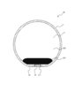
- FIG. 3 is a cross-sectional view of the enclosure 20 according to the first embodiment of the present invention.
- the enclosure 20 is formed in a hollow shape, and the magnetic fluid 221 is enclosed inside.
- the enclosure 20 is formed of a transparent material in a hollow shape, and has a main body 21 in which an opening 211 for inserting the magnetic fluid 221 is formed, a complex 22 enclosed in the main body 21, and an opening 211 And a seal member 24 covering the lid 23.
- the main body 21 is formed of, for example, a transparent material such as glass or resin.
- the enclosure 20 is disposed overlapping the contact surface of the gantry 10 (see FIG. 1) with the portion where the opening 211 is formed as the bottom surface.
- the main body 21 is formed in a dome shape that bulges in a direction opposite to the direction in which the bottom surface is formed.
- the main body 21 is formed in a substantially spherical shape. That is, in addition to the direction opposite to the direction in which the bottom surface was formed, it is formed in the shape which bulges also in the direction orthogonal to the direction in which the bottom surface was formed.
- the main body 21 is not limited to a substantially spherical shape, but may have any shape as long as it has a dome shape.
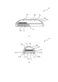
- FIG. 4 is an enlarged cross-sectional view of the vicinity of the opening 211 of the encapsulant 20 according to the first embodiment and the modification of the present invention.
- Fig.4 (a) is an expanded sectional view of opening part 211 periphery of the enclosure 20 which concerns on 1st Embodiment of this invention
- FIG.4 (b) is an opening of the enclosure 20 which concerns on the modification 1 of this invention.
- FIG. 4C is an enlarged cross-sectional view of an area around an opening 211 of an encapsulant 20 according to a second modification of the present invention.
- FIG.4 (d) is an expanded sectional view of opening part 211 periphery of the enclosure 20 which concerns on the modification 3 of this invention.
- the opening part 211 of the enclosure 20 which concerns on 1st Embodiment is obstruct
- the peripheral portion of the recessed portion of the lid 23 is locked to the side edge forming the opening 211.
- the lid 23 is covered with a seal member 24 made of a waterproof material such as silicon in a state where the lid 23 is attached to the opening 211.
- the magnetic fluid which is nanoparticles leaks with a small gap
- the arrangement of the opening of the container containing the magnetic fluid in the lower part is avoided.
- the chemical fluid is used. It is possible to prevent the magnetic fluid 221 from leaking from the opening 211 by covering the lid 23 with a seal member 24 made of silicon resin or the like which is stable.
- the outer side edge of the opening portion 211 is inclined downward and inward toward the opening portion 211. .
- a portion around the recessed portion of the lid 23 is locked to the downwardly inclined side edge forming the opening 211.
- the opening 211 according to the second modification is closed by a lid 23a formed of the same material as the main body 21 and having the same thickness.
- the side edge of the lid 23a and the side edge of the opening 211 are bonded, for example, by a seal member 24a which is an ultraviolet curing adhesive.
- the lid 23 is made of, for example, a poly stopper, a resin stopper, a glass stopper, or a rubber stopper, and the inner surface is coated with water and oil, and the magnetic fluid is repelled. Good.
- a magnetic material such as iron may be inserted into the recess of the lid 23 to enhance the magnetic force.
- the shape of the lid 23 may be made into a three-dimensional shape such as a conical shape protruding inside the enclosure 20, and a magnetic material such as iron may be inserted inside the three-dimensional shape.
- the opening 211 according to the third modification is closed only by the lid 23 made of silicon.
- the opening 211 is filled with the sealing member (for example, a silicon material) so as to fill the opening 211.
- the curing of the seal member functions in the same manner as the lid.
- the complex 22 includes the magnetic fluid 221 and the water 222.
- the water 222 is general water, and may be tap water, pure water, or the like.
- the magnetic fluid 221 is a known oil-based magnetic fluid and is a ferrite system such as Fe ferrite (that is, magnetite), Mn ferrite, Co ferrite, Ni ferrite, Zn ferrite, Mn-Co ferrite, Mo-Ni ferrite and Mo-Zn ferrite.
- the magnetic particles of the present invention are finely dispersed in an oil-based dispersion medium such as kerosene in the presence of a surfactant such as oleic acid.
- the composite 22 may further include a hard magnetic shielding piece having a known predetermined color.
- the non-magnetic light shielding piece is in the form of a thin microfilm having hydrophilicity, oil affinity, low magnetism and light shielding properties.
- Example of experiment In the experimental example, the size of the magnet brought close to the enclosure 20 (see FIG. 3) and the distance between the magnet and the enclosure 20 in the first embodiment are changed to change the form formed by the magnetic fluid 221 (see FIG. 3). Observed. The amount of the magnetic fluid 221 in the enclosure 20 of the experimental example was about 2 ml, and (manufactured by Sigma High Chemical Co., Ltd., Model No. DS-60) was used as the magnetic fluid.
- FIG. 7 is a table showing the results of the experimental example.
- FIG. 7A shows the magnetic force (kG) at the center of the pole face, the number of thorns in the center of the magnetic fluid 221, and the number of thorns in the periphery when magnets of different sizes are brought into close contact with the enclosure 20. And the result of having measured height of the center thorn shape is shown. According to the results shown in FIG. 7A, when the magnetic force at the center of the pole face is substantially equal, the number of central thorn shapes, the number of peripheral thorn shapes, and the height of central thorn shapes increase as the diameter of the magnet increases. Was confirmed to increase.
- FIG. 7 (b) shows the center of the magnetic fluid 221 when the distance (GAP) from the enclosure 20 is increased by the same neodymium magnet (diameter 10 mm, height 16 mm, central magnetic field 4.3 kG). It shows the results of measuring the number of spikes and the number of spikes around it.
- FIG. 7 (c) shows the magnetic fluid 221 when the distance (GAP) from the inclusion body 20 is increased by the same neodymium magnet (diameter 10 mm, height 10.8 mm, central magnetic field 4.4 kG). The figure shows the results of counting the number of central spikes and the number of peripheral spikes.
- the value of the "central magnetic field" in the experimental example is the magnetic force at the center of the pole face.
- FIG. 7D shows the magnetic force (kG) at the center of the pole face and the center of the magnetic fluid 221 when the height is changed by stacking neodymium magnets having the same diameter (10 mm) and a height of 1.8 mm. It shows the results of measuring the number of spikes, the number of spikes in the periphery and the height of the spikes in the center. From the results shown in FIG. 7D, the number of spikes in the center, the number of spikes in the periphery, and the height of spikes in the center increase as the product number (height) of magnets increases to less than a predetermined value. Although it became large, it has confirmed that a change was lose
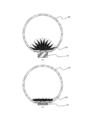
- FIG. 8 is a view schematically showing a part of the result of the present experimental example.
- FIG. 8A is a view schematically showing a thorn-shaped aspect of the magnetic fluid 221 when a magnet having a diameter of 10 mm and a height of 14.4 mm is abutted on the enclosure 20.
- FIG. 8B is a view schematically showing a thorn-shaped aspect of the magnetic fluid 221 when a magnet having a diameter of 10 mm and a height of 3.6 mm is abutted on the enclosure 20. As shown in FIG.
- the height of the magnet is higher than in the example shown in FIG. 8B, so the magnetic force lines (dotted lines in FIG. 8) rise in the vertical direction.
- the shape of the thorn appears upward also in the central portion.
- the height of the magnet is lower than in the example shown in FIG. 8A, so the magnetic force lines (dotted lines in FIG. 8) spread in the horizontal direction.
- the barb shape does not appear upward at the central portion, and a large number of barb shapes appear only in the horizontal direction (for example, see FIG. 9 described later).
- FIG. 9 is a view for explaining the configuration of a magnetic fluid control device 1A according to a second embodiment of the present invention.
- Fig.9 (a) is a figure which shows the 1st aspect of the magnetic fluid control apparatus 1A
- FIG.9 (b) is a figure which shows the 2nd aspect of the magnetic fluid control apparatus 1A.
- the magnetic fluid control device 1A includes a gantry 10A and an enclosure 20A disposed so as to overlap the abutment surface of the gantry 10A.
- FIG. 9 is a view in which the magnetic fluid control device 1A is viewed from the side of the enclosure 20A in the direction of the gantry 10A.
- information consisting of a plurality of characters, figures, etc. (in the example shown in FIG. 9, a display such as “present” shown in (a), a display such as “absent” shown in (b)) is displayed And is movable relative to the gantry 10.
- FIG. 10 is a cross-sectional view of the magnetic fluid control device 1A shown in FIG. 10 (a) is a cross-sectional view taken along the line AA 'shown in FIG. 9, and FIG. 10 (b) is a cross-sectional view taken along the line BB' shown in FIG.
- the gantry 10A includes a gantry body 11A and a magnet 12 disposed inside the gantry body 11A.
- the gantry body 11A is made of, for example, wooden or resin, and the magnet 12 is disposed in a space formed inside.
- the gantry body 11A is formed with a groove 111A engaging with a part of the enclosure 20A on at least a part of the side surface in sliding contact with the enclosure 20A.
- the enclosure 20A like the enclosure 20 (see FIG. 3), encloses the magnetic fluid 221, and comprises a main body 21A, a lid (not shown) and a seal member (not shown).
- the shape of the outer shape is different from that of the enclosure 20.
- the main body 21A has a substantially rectangular outer shape when the direction of the gantry 10A is viewed from the side of the enclosure 20A of the magnetic fluid control device 1A.
- a plurality of information in the example shown in FIG. 9, in the example shown in FIG. 9, a display such as “present” shown in (a), a display such as “absent” shown in (b)
- the main body 21A is formed in a dome shape that bulges in the direction opposite to the direction in which the bottom surface is formed.
- the main body 21A protrudes toward the gantry 10A, and a protrusion 211A is formed in sliding contact with the side surface of the gantry main body 11A.
- the protrusion 211A is formed with a protrusion 212A that protrudes toward the gantry body 11A and engages with the groove 111A of the gantry body 11A.
- the magnetic fluid control device 1A causes the enclosure 20A to slide along the side of the gantry 10A with respect to the gantry 10A by engaging the groove 111A of the gantry 10A and the projection 212A of the enclosure 20A. Can.
- the magnetic fluid control device 1A it is possible to cause the magnetic fluid control device 1A to function as an information display device.
- the user arranges the enclosure 20A at a position overlapping the magnet 12 of the gantry 10A such that one piece of information (for example, an indication such as "absent") of the enclosure 20A comes.
- one piece of information for example, an indication such as "absent”
- the magnetic fluid 221 in the enclosure 20A overlaps with one of the information, it becomes a shape due to the spike phenomenon.
- the other information for example, a display such as “present” can be visually recognized, and the state shown in FIG. 9A is obtained.
- the user moves the enclosure 20A with respect to the gantry 10A so that the other information (for example, indication of "present”, etc.) of the enclosure 20A comes to a position overlapping the magnet 12 of the gantry 10A.
- the inclusion body 20A is placed.
- the other information for example, the indication of "present” or the like
- one information for example, the indication of "absent” or the like
- Such a magnetic fluid control device 1A can use the magnetic fluid 221 to selectively display information in an aesthetically pleasing manner.
- the magnetic fluid control device 1A is not limited to a mode in which the enclosure 20A can be slide-moved with respect to the gantry 10A, as long as a plurality of pieces of information can be selectively displayed. can do.
Landscapes
- Engineering & Computer Science (AREA)
- Power Engineering (AREA)
- Business, Economics & Management (AREA)
- Accounting & Taxation (AREA)
- Marketing (AREA)
- Physics & Mathematics (AREA)
- General Physics & Mathematics (AREA)
- Theoretical Computer Science (AREA)
- Soft Magnetic Materials (AREA)
- Toys (AREA)
Abstract
Selon la présente invention, une partie en relief d'un ferrofluide où un phénomène de pointe s'est produit est rendue visuellement reconnaissable sans obstruer un champ de vision. Un dispositif de commande de ferrofluide (1) comprend : un socle (10) comportant un aimant (12) ; et un corps d'étanchéité (20) qui est disposé de façon à être superposé sur le socle (10) et qui revêt une forme creuse, le corps d'étanchéité (20) renfermant un ferrofluide (221) de manière étanche. Le corps d'étanchéité (20) comporte : une unité de corps (21) formée à partir d'un matériau transparent, une ouverture (211) pour insérer le ferrofluide (221) étant formé dans l'unité de corps (21) ; et un couvercle (23) pour fermer l'ouverture (211) de l'unité de corps (21). Le corps d'étanchéité est disposé de manière à être superposé sur le socle (10), une partie du corps (21) où l'ouverture (211) est formée servant de surface inférieure. Une unité de corps (10) revêt la forme d'un dôme bombé dans une direction opposée à la direction dans laquelle la surface inférieure est formée.
Priority Applications (1)
| Application Number | Priority Date | Filing Date | Title |
|---|---|---|---|
| JP2019546988A JPWO2019069990A1 (ja) | 2017-10-05 | 2018-10-03 | 磁性流体制御装置 |
Applications Claiming Priority (2)
| Application Number | Priority Date | Filing Date | Title |
|---|---|---|---|
| JP2017-194852 | 2017-10-05 | ||
| JP2017194852 | 2017-10-05 |
Publications (1)
| Publication Number | Publication Date |
|---|---|
| WO2019069990A1 true WO2019069990A1 (fr) | 2019-04-11 |
Family
ID=65995165
Family Applications (1)
| Application Number | Title | Priority Date | Filing Date |
|---|---|---|---|
| PCT/JP2018/037070 Ceased WO2019069990A1 (fr) | 2017-10-05 | 2018-10-03 | Dispositif de commande de ferrofluide |
Country Status (2)
| Country | Link |
|---|---|
| JP (1) | JPWO2019069990A1 (fr) |
| WO (1) | WO2019069990A1 (fr) |
Cited By (1)
| Publication number | Priority date | Publication date | Assignee | Title |
|---|---|---|---|---|
| EP3770927A1 (fr) * | 2019-07-23 | 2021-01-27 | Cartier International AG | Système ferrofluide contenant des particules d'or |
Citations (6)
| Publication number | Priority date | Publication date | Assignee | Title |
|---|---|---|---|---|
| US3648269A (en) * | 1970-07-16 | 1972-03-07 | Ferrofluidics Corp | Magnetic fluid display device |
| JPS582873A (ja) * | 1981-06-29 | 1983-01-08 | 新日曹化工株式会社 | 液体浮遊装置 |
| JPS5825200U (ja) * | 1981-08-12 | 1983-02-17 | 田中 雅量 | マグネツト活用造形遊戯具 |
| JPH01201293A (ja) * | 1988-02-04 | 1989-08-14 | Sumitomo Cement Co Ltd | 相溶性を有しない液体中の磁性流体の変形、移動を利用した器具類 |
| US6290894B1 (en) * | 1999-03-24 | 2001-09-18 | Ferrofluidics Corporation | Ferrofluid sculpting apparatus |
| JP2013244733A (ja) * | 2012-05-29 | 2013-12-09 | Art Print Japan:Kk | ウォータードーム型カレンダー |
-
2018
- 2018-10-03 JP JP2019546988A patent/JPWO2019069990A1/ja active Pending
- 2018-10-03 WO PCT/JP2018/037070 patent/WO2019069990A1/fr not_active Ceased
Patent Citations (6)
| Publication number | Priority date | Publication date | Assignee | Title |
|---|---|---|---|---|
| US3648269A (en) * | 1970-07-16 | 1972-03-07 | Ferrofluidics Corp | Magnetic fluid display device |
| JPS582873A (ja) * | 1981-06-29 | 1983-01-08 | 新日曹化工株式会社 | 液体浮遊装置 |
| JPS5825200U (ja) * | 1981-08-12 | 1983-02-17 | 田中 雅量 | マグネツト活用造形遊戯具 |
| JPH01201293A (ja) * | 1988-02-04 | 1989-08-14 | Sumitomo Cement Co Ltd | 相溶性を有しない液体中の磁性流体の変形、移動を利用した器具類 |
| US6290894B1 (en) * | 1999-03-24 | 2001-09-18 | Ferrofluidics Corporation | Ferrofluid sculpting apparatus |
| JP2013244733A (ja) * | 2012-05-29 | 2013-12-09 | Art Print Japan:Kk | ウォータードーム型カレンダー |
Non-Patent Citations (1)
| Title |
|---|
| "magnetic fluid inclusion display", SPIKE BALL, 24 December 2016 (2016-12-24), pages 1 - 2, Retrieved from the Internet <URL:https://web.archive.org/web/20161224092047/http://sigma-hc.co.jp/spikeball.html> [retrieved on 20181205] * |
Cited By (2)
| Publication number | Priority date | Publication date | Assignee | Title |
|---|---|---|---|---|
| EP3770927A1 (fr) * | 2019-07-23 | 2021-01-27 | Cartier International AG | Système ferrofluide contenant des particules d'or |
| WO2021013461A1 (fr) * | 2019-07-23 | 2021-01-28 | Cartier International Ag | Système de ferrofluide contenant des particules d'or |
Also Published As
| Publication number | Publication date |
|---|---|
| JPWO2019069990A1 (ja) | 2020-11-26 |
Similar Documents
| Publication | Publication Date | Title |
|---|---|---|
| KR200470862Y1 (ko) | 홀 아이씨 구동용 차폐자석이 구비된 휴대폰 케이스 | |
| US20080055546A1 (en) | Dynamic Projector Refresh Rate Adjustment Via PWM Control | |
| KR102416316B1 (ko) | 래디얼 마그넷 액추에이터 | |
| US10037089B2 (en) | Electromagnetic writing apparatus for electro-optic displays | |
| JP2008528312A5 (fr) | ||
| CN103019507A (zh) | 一种基于人脸跟踪改变视点角度显示三维图形的方法 | |
| WO2019069990A1 (fr) | Dispositif de commande de ferrofluide | |
| US11086417B2 (en) | Stylus for addressing magnetically-actuated display medium | |
| US20080055401A1 (en) | Stereographic Imaging System Using Open Loop Magnetomechanically Resonant Polarizing Filter Actuator | |
| CN106019762A (zh) | 一种裸眼3d透镜显示设备及其制作方法 | |
| CN105866990B (zh) | 一种显示装置 | |
| JP2014238493A (ja) | 展示装置 | |
| JPH02501012A (ja) | 表示装置 | |
| US8860783B2 (en) | Quasi-three-dimensional display apparatus | |
| JP6326139B2 (ja) | 展示用磁性流体コンポジット及び磁性流体コンポジット展示装置 | |
| US8264525B2 (en) | Closed loop feedback control to maximize stereo separation in 3D imaging systems | |
| KR102652778B1 (ko) | 디스플레이 | |
| CN220821006U (zh) | 一种磁流体形态精准控制装置及显示装置 | |
| CN208993354U (zh) | 一种基于磁液的书画装置 | |
| CN105807434A (zh) | 一种裸眼3d显示观看区域提醒方法 | |
| CN221899444U (zh) | 一种动态磁力线显示组件 | |
| JP2003032706A (ja) | 平面視テレビ兼用実体視テレビ | |
| Asahina et al. | Realistic volumetric 3D display using physical materials | |
| JP2522224Y2 (ja) | 磁気ディスプレイ装置 | |
| CN107045244A (zh) | 一种通过电磁场控制屏幕内极性显色粒子的液态显示屏 |
Legal Events
| Date | Code | Title | Description |
|---|---|---|---|
| 121 | Ep: the epo has been informed by wipo that ep was designated in this application |
Ref document number: 18864301 Country of ref document: EP Kind code of ref document: A1 |
|
| ENP | Entry into the national phase |
Ref document number: 2019546988 Country of ref document: JP Kind code of ref document: A |
|
| NENP | Non-entry into the national phase |
Ref country code: DE |
|
| 122 | Ep: pct application non-entry in european phase |
Ref document number: 18864301 Country of ref document: EP Kind code of ref document: A1 |