WO2019070101A1 - Procédé et dispositif de transmission ou de réception de données dans un système de communication sans fil - Google Patents
Procédé et dispositif de transmission ou de réception de données dans un système de communication sans fil Download PDFInfo
- Publication number
- WO2019070101A1 WO2019070101A1 PCT/KR2018/011699 KR2018011699W WO2019070101A1 WO 2019070101 A1 WO2019070101 A1 WO 2019070101A1 KR 2018011699 W KR2018011699 W KR 2018011699W WO 2019070101 A1 WO2019070101 A1 WO 2019070101A1
- Authority
- WO
- WIPO (PCT)
- Prior art keywords
- offset
- reference point
- base station
- information
- terminal
- Prior art date
- Legal status (The legal status is an assumption and is not a legal conclusion. Google has not performed a legal analysis and makes no representation as to the accuracy of the status listed.)
- Ceased
Links
Images



Classifications
-
- H—ELECTRICITY
- H04—ELECTRIC COMMUNICATION TECHNIQUE
- H04W—WIRELESS COMMUNICATION NETWORKS
- H04W56/00—Synchronisation arrangements
- H04W56/001—Synchronization between nodes
-
- H—ELECTRICITY
- H04—ELECTRIC COMMUNICATION TECHNIQUE
- H04L—TRANSMISSION OF DIGITAL INFORMATION, e.g. TELEGRAPHIC COMMUNICATION
- H04L5/00—Arrangements affording multiple use of the transmission path
-
- H—ELECTRICITY
- H04—ELECTRIC COMMUNICATION TECHNIQUE
- H04L—TRANSMISSION OF DIGITAL INFORMATION, e.g. TELEGRAPHIC COMMUNICATION
- H04L5/00—Arrangements affording multiple use of the transmission path
- H04L5/0001—Arrangements for dividing the transmission path
- H04L5/0003—Two-dimensional division
- H04L5/0005—Time-frequency
- H04L5/0007—Time-frequency the frequencies being orthogonal, e.g. OFDM(A) or DMT
- H04L5/001—Time-frequency the frequencies being orthogonal, e.g. OFDM(A) or DMT the frequencies being arranged in component carriers
-
- H—ELECTRICITY
- H04—ELECTRIC COMMUNICATION TECHNIQUE
- H04W—WIRELESS COMMUNICATION NETWORKS
- H04W56/00—Synchronisation arrangements
-
- H—ELECTRICITY
- H04—ELECTRIC COMMUNICATION TECHNIQUE
- H04W—WIRELESS COMMUNICATION NETWORKS
- H04W72/00—Local resource management
- H04W72/04—Wireless resource allocation
Definitions
- the present disclosure relates to wireless communication systems, and more particularly, to a method for transmitting and receiving data and a device for supporting the same.
- the mobile communication system has been developed to provide voice service while ensuring the user 's activity.
- the mobile communication system has expanded the area from voice to data service.
- Due to an explosion of traffic a shortage of resources is caused and users demand a higher speed service. Therefore, a more advanced mobile communication system is required .
- next-generation mobile communication system largely depend on the acceptance of explosive data traffic, the dramatic increase in the rate per user, the acceptance of a significantly increased number of connected devices, very low end-to-end latency, Should be able to.
- a dual connectivity a massive multiple input multiple output (MIMO), an in-band full duplex, a non-orthogonal multiple access (NOMA) wideband support, and device networking.
- MIMO massive multiple input multiple output
- NOMA non-orthogonal multiple access
- the present specification also aims at providing a method of using information of PRB0 corresponding to a reference point common to each numerology.
- the present disclosure provides a method for transmitting and receiving data based on a grid of a common resource block (RB) in a wireless communication system.
- RB common resource block
- a method performed by a terminal includes: receiving a synchronization block (SSB) from a base station; Receiving first offset information indicating an offset between a lowest subcarrier of the lowest resource block of the SSB and a first reference point based on a specific subcarrier spacing from the base station; ; Receiving control information including information on the specific subcarrier interval and information on a difference between a reference point based on a subcarrier interval at which the SSB is received and the first reference point from the base station; Setting a grid of a common resource block (RB) based on the first offset information and the control information; And transmitting and receiving the data to and from the base station based on the common resource block grid.
- SSB synchronization block
- the method further includes receiving from the base station second offset information indicating an additional offset associated with an offset between a lowest subcarrier of the lowest resource block of the SSB and a second reference point .
- the additional offset indicates an offset between the first reference point and the second reference point.
- the additional offset is set in a bandwidth part (BWP) set for the terminal.
- BWP bandwidth part
- the second offset information indicating the additional offset is received from the base station when the start position of the set BWP exceeds the first reference point.
- the first offset information and the control information are received from the base station through system information.
- system information is a master information block (MIB).
- MIB master information block
- the present invention also provides a method for transmitting and receiving data in a wireless communication system, the method comprising: transmitting a synchronization block (SSB) to a terminal; Transmitting first offset information indicating an offset between a lowest subcarrier of the lowest resource block of the SSB and a first reference point based on a subcarrier spacing to the UE; ; Transmitting control information including information on the specific subcarrier interval and control information based on a difference between a reference point based on a subcarrier interval at which the SSB is received and the first reference point; And transmitting and receiving the data to and from the terminal based on a grid of a resource block (RB) and a common resource block (RB).
- RB resource block
- RB common resource block
- the method further includes transmitting to the UE second offset information indicating an additional offset associated with an offset between a lowest subcarrier of the lowest resource block of the SSB and a second reference point .
- the present invention provides a terminal for transmitting and receiving data in a wireless communication system, the terminal comprising: a radio frequency (RF) module for transmitting and receiving a radio signal; And a processor operatively coupled to the RF module, the processor receiving a synchronization block (SSB) from a base station; From the base station, first offset information indicating an offset between a lowest subcarrier of the lowest resource block of the SSB and a first reference point based on a subcarrier spacing; From the base station, control information including information on the specific subcarrier interval and information on a difference between a reference point based on a subcarrier interval at which the SSB is received and the first reference point; Setting a grid of a common resource block (RB) based on the first offset information and the control information; And to transmit and receive the data to and from the base station based on the common resource block grid.
- RF radio frequency
- a processor operatively coupled to the RF module, the processor receiving a synchronization block (SSB) from
- the present specification has the effect of forming a common PRB grid by providing additional offset information for determining a reference point when the system bandwidth is increased as the performance of the system increases.
- the present specification uses the information of PRB0 corresponding to a reference point common to each numerology, thereby making it possible to prevent signaling overhead.
- FIG. 1 is a diagram showing an example of the overall system structure of NR to which the method suggested in the present specification can be applied.
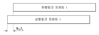
- FIG. 2 illustrates a relationship between an uplink frame and a downlink frame in a wireless communication system to which the method proposed in the present invention can be applied.
- FIG. 3 shows an example of a resource grid supported in a wireless communication system to which the method proposed here can be applied.
- FIG. 4 shows an example of a self-contained subframe structure to which the method proposed herein can be applied.
- FIG. 5 is a diagram illustrating an example of an additional offset setting method proposed in the present specification.
- FIG 6 illustrates an example of additional offset settings for the BWP proposed herein.
- FIG. 7 is a diagram illustrating an example of a partial common PRB indexing setting method proposed in the present specification.
- FIG. 8 shows an example of different subcarrier offsets between floating synchronization and data PRB in different neurors.
- FIG. 10 is a diagram illustrating an example of an operation method of a terminal implementing the method proposed in the present specification.
- FIG. 11 is a diagram showing an example of a method of operating a base station implementing the method proposed in the present specification.
- FIG. 12 illustrates a block diagram of a wireless communication device to which the methods proposed herein may be applied.
- FIG. 13 illustrates a block diagram of a communication apparatus according to an embodiment of the present invention.
- a base station has a meaning as a terminal node of a network that directly communicates with a terminal.
- the particular operation described herein as performed by the base station may be performed by an upper node of the base station, as the case may be. That is, it is apparent that various operations performed for communication with a terminal in a network including a plurality of network nodes including a base station can be performed by a network node other than the base station or the base station.
- BS base station
- BS refers to a term such as a fixed station, a Node B, an evolved NodeB, a base transceiver system (BTS), an access point (AP), a gNB (generation NB) Lt; / RTI >
- a 'terminal' may be fixed or mobile and may be a mobile station (UE), a mobile station (MS), a user terminal (UT), a mobile subscriber station (MSS), a subscriber station (SS) Advanced Mobile Station (WT), Wireless Terminal (WT), Machine-Type Communication (MTC), Machine-to-Machine (M2M), and Device-to-Device (D2D) devices.
- UE mobile station
- MS mobile station
- UT user terminal
- MSS mobile subscriber station
- SS Subscriber station
- WT Wireless Terminal
- MTC Machine-Type Communication
- M2M Machine-to-Machine
- D2D Device-to-Device
- a downlink means communication from a base station to a terminal
- an uplink means communication from a terminal to a base station.
- the transmitter may be part of the base station, and the receiver may be part of the terminal.
- the transmitter may be part of the terminal and the receiver may be part of the base station.
- CDMA code division multiple access
- FDMA frequency division multiple access
- TDMA time division multiple access
- OFDMA orthogonal frequency division multiple access
- SC- single carrier frequency division multiple access
- CDMA can be implemented with radio technology such as universal terrestrial radio access (UTRA) or CDMA2000.
- TDMA can be implemented with wireless technologies such as global system for mobile communications (GSM) / general packet radio service (GPRS) / enhanced data rates for GSM evolution (EDGE).
- OFDMA can be implemented with wireless technologies such as IEEE 802.11 (Wi-Fi), IEEE 802.16 (WiMAX), IEEE 802-20, and evolved UTRA (E-UTRA).
- UTRA is part of the universal mobile telecommunications system (UMTS).
- 3GPP (3rd Generation Partnership Project) LTE (Long Term Evolution) is part of E-UMTS (evolved UMTS) using E-UTRA, adopting OFDMA in downlink and SC-FDMA in uplink.
- LTE-A (advanced) is the evolution of 3GPP LTE.
- 5G NR new radio
- eMBB enhanced mobile broadband
- mMTC massive machine type communications
- URLLC ultra-reliable low latency communications
- V2X vehicle-to-everything
- the 5G NR standard distinguishes between standalone (SA) and non-standalone (NSA) depending on the co-existence between the NR system and the LTE system.
- the 5G NR supports various subcarrier spacing, CP-OFDM in the downlink, CP-OFDM in the uplink, and DFT-s-OFDM (SC-OFDM).
- Embodiments of the present invention may be supported by standard documents disclosed in at least one of the wireless access systems IEEE 802, 3GPP and 3GPP2. That is, the steps or portions of the embodiments of the present invention which are not described in order to clearly illustrate the technical idea of the present invention can be supported by the documents. In addition, all terms disclosed in this document may be described by the standard document.
- 3GPP LTE / LTE-A / NR New RAT
- the eLTE eNB is an eNB evolution that supports connectivity to EPC and NGC.
- gNB node that supports NR as well as connection to NGC.
- New RAN A wireless access network that supports NR or E-UTRA or interacts with NGC.
- Network slice is a network defined by an operator to provide an optimized solution for a specific market scenario that requires specific requirements with end-to-end coverage.
- Network function is a logical node within a network infrastructure with well-defined external interfaces and well-defined functional behavior.
- NG-C Control plane interface used for NG2 reference point between new RAN and NGC.
- NG-U User plane interface used for NG3 reference points between new RAN and NGC.
- Non-standalone NR A configuration in which gNB requests an LTE eNB as an anchor for EPC control plane connection or an eLTE eNB as an anchor for control plane connection to NGC.
- Non-stand-alone E-UTRA A deployment configuration in which the eLTE eNB requires the gNB as an anchor for the control plane connection to the NGC.
- User plane gateway Endpoint of the NG-U interface.
- FIG. 1 is a diagram showing an example of the overall system structure of NR to which the method suggested in the present specification can be applied.
- the NG-RAN comprises gNBs providing a control plane (RRC) protocol termination for the NG-RA user plane (new AS sublayer / PDCP / RLC / MAC / PHY) and UE do.
- RRC control plane
- the gNBs are interconnected via the Xn interface.
- the gNB is also connected to the NGC via the NG interface.
- the gNB is connected to an Access and Mobility Management Function (AMF) through an N2 interface and a UPF (User Plane Function) through an N3 interface.
- AMF Access and Mobility Management Function
- UPF User Plane Function
- the memoryless can be defined by the subcarrier spacing and the CP (Cyclic Prefix) overhead.
- the plurality of subcarrier intervals are set to a constant N (or alternatively, ) ≪ / RTI >
- the utilized memoryless can be chosen independently of the frequency band.
- OFDM Orthogonal Frequency Division Multiplexing
- the number of OFDM neuron rolls supported in the NR system can be defined as shown in Table 1.
- the size of the various fields in the time domain is Lt; / RTI > units of time. From here, ego, to be.
- the downlink and uplink transmissions are And a radio frame having a duration of.
- FIG. 2 illustrates a relationship between an uplink frame and a downlink frame in a wireless communication system to which the method proposed in the present invention can be applied.
- the transmission of the uplink frame number i from the User Equipment (UE) is shorter than the start of the corresponding downlink frame in the corresponding UE You have to start before.
- Not all terminals can transmit and receive at the same time, meaning that not all OFDM symbols of a downlink slot or an uplink slot can be used.
- Table 2 & , And Table 3 shows the number of OFDM symbols per slot for a normal CP Represents the number of OFDM symbols per slot for an extended CP in the slot.
- An antenna port, a resource grid, a resource element, a resource block, a carrier part, and the like are associated with a physical resource in the NR system. Can be considered.
- the antenna port is defined such that the channel on which the symbols on the antenna port are carried can be deduced from the channel on which the other symbols on the same antenna port are carried. If a large-scale property of a channel on which a symbol on one antenna port is carried can be deduced from a channel on which symbols on another antenna port are carried, the two antenna ports may be quasi co-located (QC / QCL) quasi co-location relationship.
- the broad characteristics include at least one of a delay spread, a Doppler spread, a frequency shift, an average received power, and a received timing.
- FIG. 3 shows an example of a resource grid supported in a wireless communication system to which the method proposed here can be applied.
- Subcarriers if the resource grid is in the frequency domain Subcarriers, and one subframe consists of 14 x 2 u OFDM symbols, but is not limited thereto.
- antenna port p can be set to one resource grid.
- each element of the resource grid for antenna port p is referred to as a resource element, ≪ / RTI > From here, Is an index in the frequency domain, Quot; refers to the position of a symbol in a subframe.
- a resource element in a slot From here, to be.
- a physical resource block is a block in the frequency domain Are defined as consecutive subcarriers. On the frequency domain, .
- a terminal may be configured to receive or transmit using only a subset of the resource grid. At this time, a set of resource blocks set to be received or transmitted by the UE is set to 0 .
- FIG. 4 is a diagram illustrating a self-contained subframe structure in a wireless communication system to which the present invention may be applied.
- a self-contained subframe structure as shown in FIG. 4 is considered in the 5G (5G) new RAT.
- the hatched area represents a DL control area and the black area (symbol index 13) represents an UL control area.
- the area without shadow indication may be used for DL data transmission, or may be used for UL data transmission.
- This structure is characterized in that DL transmission and UL transmission sequentially proceed in one subframe, DL data is transmitted in a subframe, and UL ACK / NACK can also be received. As a result, it takes less time to retransmit data when a data transmission error occurs, thereby minimizing the latency of final data transmission.
- a time gap is required between the base station and the UE for switching from the transmission mode to the reception mode or from the reception mode to the transmission mode.
- some OFDM symbols at the time of switching from DL to UL in the self-contained subframe structure are set as a guard period (GP).
- the wavelength is shortened so that a plurality of antenna elements can be installed in the same area. That is, in a 30 GHz band, a total of 64 (8 ⁇ 8) antenna elements are arranged in a two-dimensional array at 0.5 lambda (ie, wavelength) intervals on a panel of 4 ⁇ 4 (4 by 4) Installation is possible. Therefore, in the case of mmW, a plurality of antenna elements are used to increase the beamforming (BF) gain to increase the coverage or increase the throughput.
- BF beamforming
- TXRU Transceiver Unit
- TXRU Transceiver Unit
- independent beamforming is possible for each frequency resource.
- installing the TXRU on all 100 antenna elements has a problem in terms of cost effectiveness. Therefore, a method of mapping a plurality of antenna elements to one TXRU and adjusting the direction of a beam with an analog phase shifter is considered.
- This analog BF method has a disadvantage in that it can not perform frequency selective BF since it can make only one beam direction in all bands.
- Hybrid beamforming (BF) with B TXRUs that are fewer than Q antenna elements in the middle of digital BF and analog BF can be considered.
- B TXRUs that are fewer than Q antenna elements in the middle of digital BF and analog BF.
- the direction of the beam that can be transmitted at the same time is limited to B or less.
- 'new release' or 'evolution of release' or 'release of higher' means higher performance of future evolved communications systems or systems after release 15, bandwidth systems.
- SS synchronization
- PBCH physical broadcast channel
- the network used herein may be interpreted in the same sense as a base station.
- the maximum number of subcarriers of an NR radio access (NR) system is 3,300, which corresponds to 275 physical resource blocks (PRBs).
- PRBs physical resource blocks
- the bandwidth corresponding to each subcarrier spacing may be 50 MHz (15 kHz subcarrier spacing), 100 MHz (30 kHz subcarrier spacing), or 200 MHz (60 kHz subcarrier spacing).
- a terminal connects to a network and forms a common PRB grid.
- the terminal receives information of PRB0, which is a reference point, from the base station.
- the reference point can be interpreted to have the same meaning as point A defined in the standard.
- point A serves as a common reference point for the resource block grid, and can be obtained as follows.
- OffsetToPointA for the PCell downlink represents the frequency offset between point A and the lowest subcarrier of the lowest resource block of the SS / PBCH block used by the terminal for initial cell selection, and is 15 kHz for FR1 (below 6 GHz) subcarrier spacing, and 60kHz subcarrier spacing for FR2 (above 6GHz).
- - absoluteFrequencyPointA represents the frequency-location of point A as expressed in ARFCN (absolute radio-frequency channel number).
- the information of the reference point PRB0 is the offset from the SS / PBCH block (SSB) connected to the terminal to the PRB0, and is represented by an integer multiple PRB.
- SSB SS / PBCH block
- the BS may set a total of 9 bits to reduce the signaling overhead for transmitting the offset information to the MS.
- the offset of 9 bits can represent a maximum of 512 PRBs.
- the configured resource (9 bits in total, up to 512 PRBs) may be insufficient for future releases (or later communication systems).
- the offset from the SS block to PRB0 can be larger because the network (or base station) or terminals supporting the new release can support larger bandwidths.
- the present disclosure provides a common PRB indexing method and an offset setting method for solving the problem that the offset can not be expressed as the release evolves as described above.
- the terminal receives an offset value from the SS block in order to use the common PRB indexing, and the bandwidth that can be supported by the system increases due to release (or future system) evolution, Provides a solution when the value is outside the range in which the value can be expressed.
- the first embodiment is for common PRB indexing for a BWP (bandwidth part) configuration.
- the common PRB indexing can be used by the base station to configure the bandwidth part (BWP) to the terminal or to configure the RS sequence.
- the SS block may be additionally set.
- the release 15 terminal can be set not to access the network in the SS block added to maintain the existing common PRB indexing.
- the network can send indication information to the terminal indicating whether the SS block (or the added SS block) is available for the release 15 terminal .
- the UE can determine whether or not the (added) SS block is used according to the indication information.
- the terminal can not use the added SS block (for example, the terminal receives an out-of-range indication from the base station), the terminal can perform a procedure of searching for a new SS block .
- the network can be configured as follows.
- Offset from PRB0 to SS block is transmitted using remaining minimum system information (RMSI), and additional offset information can be transmitted using another RMSI or OSI (Other System Information).
- RMSI remaining minimum system information
- OSI Olet System Information
- the release 15 terminal forms a PRB grid that is the same as the offset received from the first RMSI.
- the release 15 terminal may receive additional offset information to form a common PRB grid.
- FIG. 5 is a diagram illustrating an example of an additional offset setting method proposed in the present specification.
- 510 indicates the SS block and PRB0 offset (original offset) in the release 15 system
- 520 indicates the SS block and PRB0 offset in the system after release 15 (release 16).
- 520 is represented by the sum of offset (original offset) and additional offset (530) in release 15.
- Method 1 can reduce the processing overhead of the release 15 terminal, while the network must determine release version information for the terminals.
- Method 2 describes how to configure the terminal to configure additional offsets in Method 1 when configuring one bandwidth part to the terminal.
- the terminal receives information related to initial BWP configuration including at least one DL BWP and UL BWP of one or two (when using a supplementary uplink (SUL)) from a network via a master information block (MIB) do.
- MIB master information block
- the terminal After setting the initial BWP, the terminal can set up additional BWP from the network.
- the terminal receives additional BWP configuration related information from the network through RRC signaling.
- the terminal receives information related to BWP switching for at least one established BWP from the network through the PDCCH.
- BWP switching means an operation of activating inactive BWP or inactivation of active BWP, and can be performed by PDCCH.
- the terminal transmits and receives signals (control and / or data) to and from the network in the active BWP based on the received PDCCH.
- the terminal can send and receive signals to and from the network via one or more active BWPs.
- Method 2 the UE accesses the network using the SS block, and receives the position f0 of PRB0, which is a reference point (or point A) for using common PRB indexing from the RMSI received from the network.
- release terminals after Release 15 may be limited to use only the bandwidth supported by Release 15 terminals even though they can use a larger bandwidth.
- Release 15 or later Release terminals require a configuration method to use a larger bandwidth.
- the network when the network configures the bandwidth part to the corresponding terminal, it can set an additional offset when the starting point of the corresponding bandwidth part (frequency position where the bandwidth part starts (or the position of the RB)) exceeds the reference point have.
- the above described scheme has an advantage that it does not increase any overhead for existing release 15 terminals and does not affect the formation of a common PRB grid after release 15.
- the additional offset value (or the offset bit or offset field) may be configured using the RMSI, or UE-specific.
- the additional offset value may use the reserved field of the RMSI.
- the indication bit is set to "0" for the release 15 terminal, and the indication bit is set to another value for the release terminal.
- the network transmits RRC signaling to the UE, and the UE can receive the corresponding information through the corresponding RRC signaling.
- initial access related configuration (including initial BWP) proceeds based on RMSI.
- the network can configure additional offset to the common PRB indexing based on RMSI.
- FIG 6 illustrates an example of additional offset settings for the BWP proposed herein.
- the additional offset indication method discussed in Method 2 can be applied not only to the BWP setting but also to the measurement configuration.
- Method 3 relates to a method for setting a plurality of " partial " common PRB indexings in the system wideband.
- FIG. 7 is a diagram illustrating an example of a partial common PRB indexing method proposed in the present specification.
- the wideband (or system BW) is divided into three sections, and common PRB indexing is set for each section.
- the network can signaling the terminals connected to the offset (offset 1, offset 2, offset 3) from each SS block to the corresponding PRB0.
- the Release 15 terminal forms a common PRB grid using the received offset based on the SS block it accesses, and receives the BWP configuration from the network based on the offset.
- the network may command intra-frequency measurement to the terminal to move the terminal to another section.
- the measure object is quasi-co-location with the currently connected SS block.
- an antenna port is defined such that the channel on which the symbol on the antenna port is carried can be deduced from the channel on which another symbol on the same antenna port is carried.
- the two antenna ports can be quasi- ) Relationship.
- the channel characteristic may be at least one of a delay spread, a Doppler spread, a frequency shift, an average received power, a received timing, and a spatial RX parameter.
- the Spatial Rx parameter means a spatial (reception) channel characteristic parameter such as an angle of arrival.
- BW section 1 For example, if a terminal using common PRB indexing in BW section 1 (110) performs measurement on SS block 1 and BW section 2 (120) with QCL and handover is performed, new offset information is received from block 2 to form a common PRB indexing, and the BWP configuration can also be performed using a common PRB indexing.
- the second embodiment relates to a method of indicating a common offset for different numerology.
- the NR system supports various numerologies, and terminals connected to the NR system can use the common PRB indexing corresponding to each numerology.
- the terminal After the terminal receives an indication of the reference point from the network, it receives the bandwidth part from the network.
- the UE checks the location of a bandwidth part configured with common PRB indexing configured using 15 kHz subcarrier spacing.
- the UE checks the location of a bandwidth part configured with common PRB indexing configured using 30 kHz subcarrier spacing.
- the UE receives the offset value from the connected SS block to PRB0 from the network.
- PRB0 based on each numerology may not be aligned in one place according to system bandwidth.
- the second embodiment provides a method of calculating the offset from the SS block to the PRB0 by providing the same offset to the UEs, while the UEs analyze each numerology.
- the second embodiment can be largely composed of two steps, and each step is as follows.
- the network can indicate to the terminal which numerology-based PRB grid is offset.
- the terminal first performs the SSB detecting process to access the network.
- the SSB detection process is a process for confirming whether SSB exists at a predetermined frequency interval, and the predetermined frequency interval is defined as a channel raster.
- the channel raster has a set value for each band.
- the channel raster value of band n1 is 100 kHz
- the channel raster value of band n41 can be 15 kHz or 30 kHz.
- 100 kHz is not an integral multiple of one PRB range (frequency of 12 subcarriers) and does not match the PRB grid for actual data transmission and reception, subcarrier offset may exist.
- the detected SS block is called a floating SS block.
- the PRB grid for the data is as follows. After the UE acquires the DL synchronization through a synchronization procedure, the SSB subcarrier offset is received through the system information (e.g., MIB) And matching the grid of SSB with the PRB grid for data to be received thereafter.
- system information e.g., MIB
- the data PRB grid described above is a subcarrier unit, it can be a maximum of 11 subcarriers.
- the offset may be represented by 4 bits.
- both the floating sync. And the subcarrier spacing of the data PRB grid are 15 kHz.
- the offset can have up to 23 subcarriers and 47 subcarriers, respectively.
- the offset values may be represented by 5 bits and 6 bits, respectively.
- the UE can determine the PRB indication from the offset format.
- the MS can determine the offset (the value indicated in the RMSI) from the SSB (from SSB) to the PRB0, which is a numerology-based offset value.
- the PRB0 offset value to be received means the number of PRBs based on the subcarrier of 15 kHz.
- the offset value of PRB0 to be received means the number of PRBs based on a 30 kHz subcarrier.
- FIG. 8 shows an example of offset between an SS block having a 15-kHz subcarrier spacing and a data PRB having a 15-kHz, 30-kHz subcarrier spacing.
- the UE can calculate the offset between the SS block and the PRB0 based on the numerology indicated in step 1 above.
- FIG. 9 shows the PRB grid situation at the end of the BW that can occur according to the system BW when the PRB grid is formed using the respective numerology.
- the terminal receives PRB0-related offset information based on a numerology (indicating from floating sync. Offset information) from the network.
- the numerology may be the same as or different from the numerology of the PRB grid to be configured by the UE.
- the terminal can form a PRB grid actually used by using the received offset.
- a UE using a subcarrier spacing of 15 kHz receives offset information of a sync block, it receives information (offset 2 information in FIG. 8) of PRB alignment based on 30 kHz SCS (subcarrier spacing) It receives an offset value (including state in information).
- the offset value expresses the number of PRBs constituted by 30 kHz subcarrier spacing.
- the terminal can calculate the PRB 0 corresponding to the numerology (15k SCS) used by the terminal.
- the state is represented by 2 bits, and may be included in the offset value of the RMSI, or may indicate a corresponding state by designating another field.
- the first 2 bits or the last 2 bits of the offset value bit field may be represented as a PRB state and the remaining bits may be interpreted as a PRB number.
- the offset value indicates the number of PRBs based on 30 kHz subcarrier spacing as described above, and the state value indicates state 2 in FIG. 9 .
- the PRB grid of each numerology shows the configuration at the carrier end.
- the PRB0 based on the 30 kHz, 60 kHz subcarrier spacing is matched, and the PRB0 based on the 15 kHz subcarrier spacing indicates a case where one PRB is shifted compared to 30 and 60 kHz.
- FIG. 10 is a diagram illustrating an example of an operation method of a terminal implementing the method proposed in the present specification.
- FIG. 10 shows operations of a terminal for transmitting and receiving data based on a grid of a common resource block (RB) in a wireless communication system.
- RB common resource block
- the terminal receives a synchronization block (SSB) from the base station (S1010).
- SSB synchronization block
- the UE receives first offset information indicating an offset between a lowest sub-carrier of the lowest resource block of the SSB and a first reference point based on a specific sub-carrier spacing, From the base station (S1020).
- the UE receives from the BS control information including information on the specific subcarrier interval and information on the difference between the reference point based on the subcarrier interval at which the SSB is received and the first reference point S1030).
- the terminal sets a grid of a common resource block (RB) based on the first offset information and the control information (S1040).
- the terminal transmits / receives the data to / from the base station based on the common resource block grid (S1050).
- the terminal may transmit second offset information indicating an additional offset associated with an offset between the lowest subcarrier of the lowest resource block of the SSB and the second reference point It can receive from the base station.
- the additional offset represents an offset between the first reference point and the second reference point.
- the additional offset may be set within a bandwidth part (BWP) set for the UE.
- BWP bandwidth part
- the second offset information indicating the additional offset may be received from the base station when the start position of the set BWP exceeds the first reference point.
- the first offset information and the control information may be received from the base station through system information, and the system information may be RMSI.
- FIG. 11 is a diagram showing an example of a method of operating a base station implementing the method proposed in the present specification.
- the base station transmits a synchronization block (SSB) to the terminal (S1110).
- SSB synchronization block
- the BS transmits first offset information indicating an offset between a lowest sub-carrier of the lowest resource block of the SSB and a first reference point based on a specific sub-carrier spacing, To the terminal (S1120).
- the BS transmits control information including information on the specific subcarrier interval and information on a difference between the reference point based on the subcarrier interval at which the SSB is received and the first reference point to the MS S1130).
- step S1140 the base station transmits and receives the data to and from the terminal based on a grid of a common resource block (RB).
- RB common resource block
- the BS may transmit second offset information indicating an additional offset associated with an offset between the lowest subcarrier of the lowest resource block of the SSB and the second reference point To the terminal.
- the additional offset is set in a bandwidth part (BWP) set for the terminal, and the additional offset is transmitted to the terminal when the start position of the BWP set in the terminal exceeds the first reference point .
- BWP bandwidth part
- FIG. 12 illustrates a block diagram of a wireless communication device to which the methods proposed herein may be applied.
- a wireless communication system includes a base station 1210 and a plurality of terminals 1220 located within a base station 1210 area.
- the BS and the MS may be represented by wireless devices, respectively.
- the base station 1210 includes a processor 1211, a memory 1212, and a radio frequency module 1213.
- Processor 1211 implements the functions, processes, and / or methods suggested earlier in FIGS. 1-11.
- the layers of the air interface protocol may be implemented by a processor.
- the memory 1212 is coupled to the processor and stores various information for driving the processor.
- the RF module 1213 is coupled to the processor to transmit and / or receive wireless signals.
- the terminal 1220 includes a processor 1221, a memory 1222, and an RF module 1223.
- the processor 1221 implements the functions, procedures and / or methods suggested in FIGS. 1-11.
- the layers of the air interface protocol may be implemented by a processor.
- Memory 1222 is coupled to the processor and stores various information for driving the processor.
- the RF module 1223 is coupled to the processor to transmit and / or receive wireless signals.
- the memories 1212 and 1222 may be internal or external to the processors 1211 and 1221 and may be coupled to the processors 1211 and 1221 in various well known means.
- the base station 1210 and / or the terminal 1220 may have a single antenna or multiple antennas.
- FIG. 13 illustrates a block diagram of a communication apparatus according to an embodiment of the present invention.
- FIG. 13 is a diagram illustrating the terminal of FIG. 12 in more detail.
- a terminal includes a processor (or a digital signal processor (DSP) 1310, an RF module (or RF unit) 1335, a power management module 1305 An antenna 1340, a battery 1355, a display 1315, a keypad 1320, a memory 1330, a SIM (Subscriber Identification Module ) card 1325 (this configuration is optional), a speaker 1345 and a microphone 1350.
- the terminal may also include a single antenna or multiple antennas .
- Processor 1310 implements the functions, processes, and / or methods suggested earlier in FIGS. 1-11.
- the layer of the air interface protocol may be implemented by a processor.
- Memory 1330 is coupled to the processor and stores information related to the operation of the processor.
- the memory may be internal or external to the processor and may be coupled to the processor by any of a variety of well known means.
- the user inputs command information such as a telephone number or the like by, for example, pressing (or touching) the button of the keypad 1320 or by voice activation using the microphone 1350.
- the processor receives such command information and processes it to perform appropriate functions, such as dialing a telephone number. Operational data may be extracted from the sim card 1325 or memory. In addition, the processor may display command information or drive information on the display 1315 for the user to recognize and also for convenience.
- RF module 1335 is coupled to the processor to transmit and / or receive RF signals.
- the processor communicates command information to the RF module to transmit, for example, a radio signal that constitutes voice communication data, to initiate communication.
- the RF module consists of a receiver and a transmitter for receiving and transmitting radio signals.
- the antenna 1340 functions to transmit and receive a radio signal. When receiving a radio signal, the RF module can transmit the signal for processing by the processor and convert the signal to baseband. The processed signal may be converted to audible or readable information output via speaker 1345.
- Embodiments in accordance with the present invention may be implemented by various means, for example, hardware, firmware, software, or a combination thereof.
- an embodiment of the present invention may include one or more application specific integrated circuits (ASICs), digital signal processors (DSPs), digital signal processing devices (DSPDs), programmable logic devices (PLDs) field programmable gate arrays, processors, controllers, microcontrollers, microprocessors, and the like.
- ASICs application specific integrated circuits
- DSPs digital signal processors
- DSPDs digital signal processing devices
- PLDs programmable logic devices
- an embodiment of the present invention may be implemented in the form of a module, a procedure, a function, or the like which performs the functions or operations described above.
- the software code can be stored in memory and driven by the processor.
- the memory is located inside or outside the processor and can exchange data with the processor by various means already known.
- the present invention can be applied to various wireless communication systems.
Landscapes
- Engineering & Computer Science (AREA)
- Signal Processing (AREA)
- Computer Networks & Wireless Communication (AREA)
- Mobile Radio Communication Systems (AREA)
Abstract
La présente invention concerne un procédé de transmission ou de réception de données sur la base d'une grille d'un bloc de ressources (RB) commun dans un système de communication sans fil. Plus spécifiquement, le procédé mis en œuvre par un terminal comprend les étapes consistant à : recevoir un bloc de signal de synchronisation d'une station de base; recevoir, en provenance de la station de base, des premières informations de décalage indiquant un décalage entre un premier point de référence sur la base d'un intervalle de sous-porteuse spécifique et une sous-porteuse la plus basse d'un bloc de ressources le plus bas dans la SSB; recevoir, de la station de base, des informations de commande comprenant des informations de l'intervalle de sous-porteuse spécifique et des informations d'une différence entre le premier point de référence et un point de référence sur la base d'un intervalle d'une sous-porteuse par laquelle la SSB est reçue; et régler un réseau de blocs de ressources commun sur la base des premières informations de décalage et des informations de commande.
Priority Applications (1)
| Application Number | Priority Date | Filing Date | Title |
|---|---|---|---|
| US16/652,819 US11337170B2 (en) | 2017-10-02 | 2018-10-02 | Method and device for transmitting or receiving data in wireless communication system |
Applications Claiming Priority (2)
| Application Number | Priority Date | Filing Date | Title |
|---|---|---|---|
| US201762567208P | 2017-10-02 | 2017-10-02 | |
| US62/567,208 | 2017-10-02 |
Publications (1)
| Publication Number | Publication Date |
|---|---|
| WO2019070101A1 true WO2019070101A1 (fr) | 2019-04-11 |
Family
ID=65994808
Family Applications (1)
| Application Number | Title | Priority Date | Filing Date |
|---|---|---|---|
| PCT/KR2018/011699 Ceased WO2019070101A1 (fr) | 2017-10-02 | 2018-10-02 | Procédé et dispositif de transmission ou de réception de données dans un système de communication sans fil |
Country Status (2)
| Country | Link |
|---|---|
| US (1) | US11337170B2 (fr) |
| WO (1) | WO2019070101A1 (fr) |
Cited By (1)
| Publication number | Priority date | Publication date | Assignee | Title |
|---|---|---|---|---|
| US11937242B2 (en) * | 2017-06-16 | 2024-03-19 | Guangdong Oppo Mobile Telecommunications Corp., Ltd. | Wireless communication method and device |
Families Citing this family (6)
| Publication number | Priority date | Publication date | Assignee | Title |
|---|---|---|---|---|
| KR102352364B1 (ko) * | 2017-06-15 | 2022-01-18 | 주식회사 아이티엘 | Nr 시스템에서 광대역 동작 방법 및 장치 |
| WO2019070101A1 (fr) * | 2017-10-02 | 2019-04-11 | 엘지전자 주식회사 | Procédé et dispositif de transmission ou de réception de données dans un système de communication sans fil |
| US11102736B2 (en) | 2017-10-24 | 2021-08-24 | Qualcomm Incorporated | Channel and synchronization raster |
| US11778657B2 (en) * | 2017-10-27 | 2023-10-03 | Apple Inc. | Control resource set information in physical broadcast channel |
| US11503518B2 (en) * | 2018-04-13 | 2022-11-15 | Qualcomm Incorporated | Reference point determination |
| CN112655258A (zh) * | 2019-03-01 | 2021-04-13 | Oppo广东移动通信有限公司 | 无线通信的方法、终端设备和网络设备 |
Citations (1)
| Publication number | Priority date | Publication date | Assignee | Title |
|---|---|---|---|---|
| WO2017135593A1 (fr) * | 2016-02-04 | 2017-08-10 | 주식회사 케이티 | Procédé pour qu'un système de communication mobile à ultra haute fréquence émette-reçoive un signal de référence et une rétroaction et appareil associé |
Family Cites Families (8)
| Publication number | Priority date | Publication date | Assignee | Title |
|---|---|---|---|---|
| EP3195677B1 (fr) * | 2016-05-11 | 2020-07-08 | Telefonaktiebolaget LM Ericsson (PUBL) | Procédé et appareil de commande d'émission de signal |
| CN111491379B (zh) * | 2017-05-05 | 2021-05-18 | 华为技术有限公司 | 资源分配的方法、用户设备和网络设备 |
| CN109462892B (zh) * | 2017-06-30 | 2019-11-19 | 华为技术有限公司 | 控制信息传输方法和设备 |
| CN109309955B (zh) * | 2017-07-28 | 2021-02-09 | 华为技术有限公司 | 一种同步信号块的传输方法、接入网设备及终端设备 |
| EP4236175B1 (fr) * | 2017-08-10 | 2026-05-06 | Samsung Electronics Co., Ltd. | Procédé et appareil permettant de déterminer les ressources de fréquence dans les réseaux cellulaires d'accès initial dans des réseaux cellulaires de la prochaine génération |
| CN109392122B (zh) * | 2017-08-10 | 2023-05-12 | 华为技术有限公司 | 数据传输方法、终端和基站 |
| WO2019061367A1 (fr) * | 2017-09-29 | 2019-04-04 | 华为技术有限公司 | Procédé de transmission de données, dispositif terminal et dispositif réseau |
| WO2019070101A1 (fr) * | 2017-10-02 | 2019-04-11 | 엘지전자 주식회사 | Procédé et dispositif de transmission ou de réception de données dans un système de communication sans fil |
-
2018
- 2018-10-02 WO PCT/KR2018/011699 patent/WO2019070101A1/fr not_active Ceased
- 2018-10-02 US US16/652,819 patent/US11337170B2/en active Active
Patent Citations (1)
| Publication number | Priority date | Publication date | Assignee | Title |
|---|---|---|---|---|
| WO2017135593A1 (fr) * | 2016-02-04 | 2017-08-10 | 주식회사 케이티 | Procédé pour qu'un système de communication mobile à ultra haute fréquence émette-reçoive un signal de référence et une rétroaction et appareil associé |
Non-Patent Citations (4)
| Title |
|---|
| "Remaining Aspects for Carrier Aggregation and Bandwidth Parts", RL-1716327, 3GPP TSG RAN WG1 MEETING NR#3, 12 September 2017 (2017-09-12), Nagoya. Japan, XP051329918 * |
| LG ELECTRONICS: "RMSI Delivery and CORESET Configuration", R1-1715842, 3GPP TSG RAN WG1 MEETING NR#3, 12 September 2017 (2017-09-12), Nagoya, Japan, XP051329534 * |
| SAMSUNG: "Remaining Issues on the NR Mobility", R 1-1715915, 3GPP TSG RAN WG1 MEETING NR#3, 12 September 2017 (2017-09-12), Nagoya, Japan, XP051329593 * |
| VIVO: "Remaining Issues on SS Block and SS Burst Set Composition", RL-1715606, 3GPP TSG RAN WG1 NR AD-HOC#3, 12 September 2017 (2017-09-12), Nagoya, Japan, XP051329415 * |
Cited By (1)
| Publication number | Priority date | Publication date | Assignee | Title |
|---|---|---|---|---|
| US11937242B2 (en) * | 2017-06-16 | 2024-03-19 | Guangdong Oppo Mobile Telecommunications Corp., Ltd. | Wireless communication method and device |
Also Published As
| Publication number | Publication date |
|---|---|
| US11337170B2 (en) | 2022-05-17 |
| US20200236638A1 (en) | 2020-07-23 |
Similar Documents
| Publication | Publication Date | Title |
|---|---|---|
| WO2019070101A1 (fr) | Procédé et dispositif de transmission ou de réception de données dans un système de communication sans fil | |
| EP3881633A1 (fr) | Procédé et appareil de gestion de retransmissions de messages durant des procédures d'accès aléatoire en 2 étapes dans un système de communication sans fil | |
| WO2018062891A1 (fr) | Procédé permettant d'émettre et de recevoir un signal de synchronisation dans un système de communication sans fil et appareil associé | |
| WO2017213420A1 (fr) | Procédé pour obtenir des informations relatives à un préfixe cyclique dans un système de communication sans fil et dispositif associé | |
| WO2019050370A1 (fr) | Procédé et dispositif d'émission et de réception de signal à l'aide d'agrégation de porteuse dans un système de communication sans fil | |
| WO2019088676A1 (fr) | Procédé pour la détermination d'une zone de ressource devant être attribuée à une partie de largeur de bande dans un système de communication sans fil, et appareil associé | |
| WO2018084618A1 (fr) | Procédé d'exécution d'accès initial dans un système de communication sans fil, et appareil correspondant | |
| WO2018030841A1 (fr) | Procédé permettant de rapporter des informations de mesure de signal de référence au moyen d'un terminal dans un système de communication sans fil et appareil prenant en charge ce dernier | |
| WO2019017755A9 (fr) | Procédé de multiplexage de signaux de référence dans un système de communication sans fils, et appareil l'utilisant | |
| WO2019022473A1 (fr) | Procédé de réalisation de mise en œuvre de partie de bande passante dans un système de communication sans fil et appareil associé | |
| WO2020036455A1 (fr) | Procédé de transmission ou de réception de signal de synchronisation dans un système v2x nr, et appareil associé | |
| WO2020226464A1 (fr) | Procédé et dispositif pour transmettre s-ssb dans nr v2x | |
| WO2020032615A1 (fr) | Procédé et appareil d'émission et de réception de données dans un système de communication sans fil | |
| WO2018016919A1 (fr) | Procédé au moyen duquel un terminal mesure une rrm dans un système de communication sans fil et dispositifs le prenant en charge | |
| WO2019168354A1 (fr) | Procédé d'émission par un terminal d'un srs dans un système de communication sans fil, et appareil correspondant | |
| WO2019124978A1 (fr) | Procédé d'émission et de réception d'informations de commande en liaison montante dans un système de communication sans fil et appareil associé | |
| WO2018231017A1 (fr) | Procédé de mise en correspondance d'un signal de référence avec une ressource physique dans un système de communication sans fil et appareil correspondant | |
| WO2019070105A1 (fr) | Procédé de mise en oeuvre d'estimation de canal au moyen d'un dmrs dans un système de communication sans fil, et appareil associé | |
| WO2025033967A1 (fr) | Procédé et appareil pour déclencher un ssb ou un sib1 à la demande dans un système de communication sans fil | |
| WO2023080487A1 (fr) | Dispositif électronique et procédé de partage dynamique de spectre dans un système de communication sans fil | |
| WO2018143748A1 (fr) | Procédé de configuration d'espace de recherche commun dans un système de communication sans fil et appareil associé | |
| WO2023211037A1 (fr) | Procédé et dispositif d'attribution de ressources dans un système de communication sans fil | |
| WO2022240139A1 (fr) | Gestion d'un intervalle de mesure multiple | |
| WO2019083249A1 (fr) | Procédé de détermination par un terminal d'une ressource de canal de commande de liaison montante dans un système de communication sans fil et terminal d'utilisation dudit procédé | |
| WO2018128503A1 (fr) | Procédé d'émission et de réception de données dans un système de communication sans fil, et dispositif correspondant |
Legal Events
| Date | Code | Title | Description |
|---|---|---|---|
| 121 | Ep: the epo has been informed by wipo that ep was designated in this application |
Ref document number: 18864117 Country of ref document: EP Kind code of ref document: A1 |
|
| NENP | Non-entry into the national phase |
Ref country code: DE |
|
| 122 | Ep: pct application non-entry in european phase |
Ref document number: 18864117 Country of ref document: EP Kind code of ref document: A1 |