WO2019073591A1 - 空気調和システム - Google Patents
空気調和システム Download PDFInfo
- Publication number
- WO2019073591A1 WO2019073591A1 PCT/JP2017/037166 JP2017037166W WO2019073591A1 WO 2019073591 A1 WO2019073591 A1 WO 2019073591A1 JP 2017037166 W JP2017037166 W JP 2017037166W WO 2019073591 A1 WO2019073591 A1 WO 2019073591A1
- Authority
- WO
- WIPO (PCT)
- Prior art keywords
- pipe
- liquid medium
- liquid
- heat exchanger
- heat
- Prior art date
- Legal status (The legal status is an assumption and is not a legal conclusion. Google has not performed a legal analysis and makes no representation as to the accuracy of the status listed.)
- Ceased
Links
Images









Classifications
-
- F—MECHANICAL ENGINEERING; LIGHTING; HEATING; WEAPONS; BLASTING
- F24—HEATING; RANGES; VENTILATING
- F24F—AIR-CONDITIONING; AIR-HUMIDIFICATION; VENTILATION; USE OF AIR CURRENTS FOR SCREENING
- F24F11/00—Control or safety arrangements
- F24F11/70—Control systems characterised by their outputs; Constructional details thereof
- F24F11/80—Control systems characterised by their outputs; Constructional details thereof for controlling the temperature of the supplied air
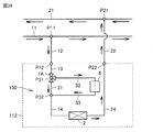
- F24F11/83—Control systems characterised by their outputs; Constructional details thereof for controlling the temperature of the supplied air by controlling the supply of heat-exchange fluids to heat-exchangers
-
- F—MECHANICAL ENGINEERING; LIGHTING; HEATING; WEAPONS; BLASTING
- F24—HEATING; RANGES; VENTILATING
- F24F—AIR-CONDITIONING; AIR-HUMIDIFICATION; VENTILATION; USE OF AIR CURRENTS FOR SCREENING
- F24F1/00—Room units for air-conditioning, e.g. separate or self-contained units or units receiving primary air from a central station
- F24F1/0007—Indoor units, e.g. fan coil units
-
- F—MECHANICAL ENGINEERING; LIGHTING; HEATING; WEAPONS; BLASTING
- F24—HEATING; RANGES; VENTILATING
- F24F—AIR-CONDITIONING; AIR-HUMIDIFICATION; VENTILATION; USE OF AIR CURRENTS FOR SCREENING
- F24F1/00—Room units for air-conditioning, e.g. separate or self-contained units or units receiving primary air from a central station
- F24F1/0007—Indoor units, e.g. fan coil units
- F24F1/0059—Indoor units, e.g. fan coil units characterised by heat exchangers
-
- F—MECHANICAL ENGINEERING; LIGHTING; HEATING; WEAPONS; BLASTING
- F24—HEATING; RANGES; VENTILATING
- F24F—AIR-CONDITIONING; AIR-HUMIDIFICATION; VENTILATION; USE OF AIR CURRENTS FOR SCREENING
- F24F1/00—Room units for air-conditioning, e.g. separate or self-contained units or units receiving primary air from a central station
- F24F1/06—Separate outdoor units, e.g. outdoor unit to be linked to a separate room comprising a compressor and a heat exchanger
- F24F1/20—Electric components for separate outdoor units
-
- F—MECHANICAL ENGINEERING; LIGHTING; HEATING; WEAPONS; BLASTING
- F24—HEATING; RANGES; VENTILATING
- F24F—AIR-CONDITIONING; AIR-HUMIDIFICATION; VENTILATION; USE OF AIR CURRENTS FOR SCREENING
- F24F11/00—Control or safety arrangements
- F24F11/30—Control or safety arrangements for purposes related to the operation of the system, e.g. for safety or monitoring
- F24F11/46—Improving electric energy efficiency or saving
-
- F—MECHANICAL ENGINEERING; LIGHTING; HEATING; WEAPONS; BLASTING
- F24—HEATING; RANGES; VENTILATING
- F24F—AIR-CONDITIONING; AIR-HUMIDIFICATION; VENTILATION; USE OF AIR CURRENTS FOR SCREENING
- F24F11/00—Control or safety arrangements
- F24F11/62—Control or safety arrangements characterised by the type of control or by internal processing, e.g. using fuzzy logic, adaptive control or estimation of values
- F24F11/63—Electronic processing
- F24F11/65—Electronic processing for selecting an operating mode
- F24F11/67—Switching between heating and cooling modes
-
- F—MECHANICAL ENGINEERING; LIGHTING; HEATING; WEAPONS; BLASTING
- F24—HEATING; RANGES; VENTILATING
- F24F—AIR-CONDITIONING; AIR-HUMIDIFICATION; VENTILATION; USE OF AIR CURRENTS FOR SCREENING
- F24F3/00—Air-conditioning systems in which conditioned primary air is supplied from one or more central stations to distributing units in the rooms or spaces where it may receive secondary treatment; Apparatus specially designed for such systems
- F24F3/06—Air-conditioning systems in which conditioned primary air is supplied from one or more central stations to distributing units in the rooms or spaces where it may receive secondary treatment; Apparatus specially designed for such systems characterised by the arrangements for the supply of heat-exchange fluid for the subsequent treatment of primary air in the room units
-
- F—MECHANICAL ENGINEERING; LIGHTING; HEATING; WEAPONS; BLASTING
- F25—REFRIGERATION OR COOLING; COMBINED HEATING AND REFRIGERATION SYSTEMS; HEAT PUMP SYSTEMS; MANUFACTURE OR STORAGE OF ICE; LIQUEFACTION SOLIDIFICATION OF GASES
- F25B—REFRIGERATION MACHINES, PLANTS OR SYSTEMS; COMBINED HEATING AND REFRIGERATION SYSTEMS; HEAT PUMP SYSTEMS
- F25B1/00—Compression machines, plants or systems with non-reversible cycle
-
- F—MECHANICAL ENGINEERING; LIGHTING; HEATING; WEAPONS; BLASTING
- F25—REFRIGERATION OR COOLING; COMBINED HEATING AND REFRIGERATION SYSTEMS; HEAT PUMP SYSTEMS; MANUFACTURE OR STORAGE OF ICE; LIQUEFACTION SOLIDIFICATION OF GASES
- F25B—REFRIGERATION MACHINES, PLANTS OR SYSTEMS; COMBINED HEATING AND REFRIGERATION SYSTEMS; HEAT PUMP SYSTEMS
- F25B2313/00—Compression machines, plants or systems with reversible cycle not otherwise provided for
- F25B2313/023—Compression machines, plants or systems with reversible cycle not otherwise provided for using multiple indoor units
- F25B2313/0233—Compression machines, plants or systems with reversible cycle not otherwise provided for using multiple indoor units in parallel arrangements
Definitions
- the present invention relates to an air conditioning system, and more particularly to an air conditioning system including a temperature control device that adjusts the temperature of a liquid medium that exchanges heat with air in an indoor heat exchanger.
- the temperature of water supplied to the load device of the heat medium is controlled to be constant (generally 5 to 7 ° C.). That is, even if the load of the load device increases or decreases, the water supply temperature does not change.
- the opening degree of the control valve provided for the load device is increased or decreased to increase or decrease the amount of hot and cold water supplied to the load device.
- Patent No. 5855279 gazette
- Patent Document 1 In the air conditioning system in which the load device individually controls the capacity as described in Japanese Patent No. 5855279 (Patent Document 1), when the load of the load device increases or decreases, the opening degree of the control valve attached to the load device The amount is increased or decreased, and the amount of cold / hot water supplied to the load device is increased or decreased. In this case, the ratio of the amount of latent heat treatment to the refrigeration capacity exhibited when lowering the temperature inside the room to the target temperature is increased. For this reason, there existed a problem that a load apparatus exhibited excess refrigeration capacity and power consumption of a heat source apparatus increased. Furthermore, there is a problem that the humidity is lowered by the unnecessary latent heat treatment, and the user feels uncomfortable because the room is dried.
- the present invention was made in order to solve the above-mentioned subject, and an object of the present invention is to provide an air conditioning system with energy saving and improved comfort.
- the present disclosure relates to an air conditioning system.
- the air conditioning system includes a heat source device, a plurality of indoor heat exchangers, and a plurality of temperature control devices.
- the heat source device is configured to heat or cool the liquid medium.
- the plurality of indoor heat exchangers are configured to be supplied with the liquid medium from the heat source device and to perform heat exchange between the liquid medium and the air.
- the plurality of temperature control devices are respectively provided corresponding to the plurality of indoor heat exchangers, and are configured to respectively adjust the temperatures of the liquid medium supplied to the plurality of indoor heat exchangers.
- Each of the plurality of temperature control devices exchanges heat between an inflow medium, which is a liquid medium supplied to the corresponding indoor heat exchanger, and an outflow medium, which is a liquid medium discharged from the corresponding indoor heat exchanger.
- the heat exchange capacity of the corresponding indoor heat exchanger is larger than the indoor load
- each of the plurality of temperature control devices increases the amount of heat exchange between the inflow medium and the outflow medium to thereby increase the corresponding room heat.
- the heat source device has a heating capacity or a cooling capacity to change the temperature of the liquid medium when none of the plurality of temperature control devices has the minimum amount of heat exchange between the inflow medium and the outflow medium.
- the air conditioning system of the present disclosure can finely adjust the temperature of the liquid refrigerant supplied to the indoor heat exchanger and can further suppress the capacity of the heat source device, temperature control can be performed while maintaining energy saving of the air conditioning system. Performance can be improved.
- FIG. 2 is a diagram representatively showing the configuration of load devices 101-1 to 101-n of FIG. 1 and the flow of a heat medium. It is a figure showing the 1st modification of a flow rate adjustment device. It is a figure showing the 2nd modification of a flow rate adjustment device. It is a figure showing the 3rd modification of a flow rate adjustment device. It is a figure showing the 4th modification of a flow rate adjustment device. 5 is a flowchart showing an operation of the heat source device 201 of the air conditioning system according to Embodiment 1.
- FIG. 5 is a flowchart showing an operation of a load device 101 of the air conditioning system according to Embodiment 1.
- FIG. 7 is a diagram showing a circuit configuration of a load device 102 and a relay device 103 according to a second embodiment and a flow of a heat medium.
- FIG. 6 is a front view of a configuration example of a liquid-liquid heat exchanger 3;
- FIG. 6 is a side view of a configuration example of a liquid-liquid heat exchanger 3;
- FIG. 6 is a perspective view of a configuration example of a liquid-liquid heat exchanger 3.
- FIG. 10 is a diagram showing a circuit configuration of a load device according to a third embodiment and a flow of a heat medium.
- FIG. 17 is a diagram showing the circuit configuration of the load device 102 and the relay device 105 according to the fourth embodiment and the flow of a heat medium.
- FIG. 18 is a diagram showing the circuit configuration of the load device 102 and the relay device 106 according to the fifth embodiment and the flow of a heat medium.
- FIG. 18 is a diagram showing a circuit configuration of a load device 102 and a relay device 107 according to a sixth embodiment and a flow of a heat medium.
- FIG. 24 is a diagram showing the circuit configuration of the load device 102 and the relay device 108 according to a modification of the sixth embodiment and the flow of a heat medium.
- FIG. 18 is a diagram showing a circuit configuration of a load device according to a seventh embodiment and a flow of a heat medium.
- FIG. 18 is a diagram showing a configuration of a first modification of a load device and a flow rate adjustment device according to a seventh embodiment.
- FIG. 21 is a diagram showing the configuration of a second modification of the load device and the flow rate adjustment device according to Embodiment 7;
- FIG. 18 is a diagram showing a configuration of a third modification of the load device and the flow rate adjustment device according to Embodiment 7.
- FIG. 24 is a diagram showing a circuit configuration of a load device 109 relating to an eighth embodiment and a flow of a heat medium. It is a flowchart for demonstrating the modification which added control of the pump to control of FIG. FIG.
- FIG. 21 is a diagram showing a modification of the circuit configuration according to the eighth embodiment.
- FIG. 18 is a diagram showing a circuit configuration of a load device according to a ninth embodiment and a flow of a heat medium.
- FIG. 21 is a diagram showing the configuration of a modification of the load device in accordance with the ninth embodiment.
- FIG. 1 is a diagram showing an overall configuration of an air conditioning system to which the temperature control device of the present embodiment is applied.
- the air conditioning system 1000 includes a heat source device 201, a control device 202, a pump WP, load devices 101-1 to 101-n, a main line 11 and a main line 21.
- the control device 202 is illustrated as an independent device, but may be built in the heat source device 201.
- the heat source apparatus 201 is an apparatus for cooling or heating the heat medium supplied to the load apparatuses 101-1 to 101-n, and the heat medium flows from the heat source apparatus 201 through the trunk pipe 11 (outbound path) It is supplied to 101-n, and is returned from the load devices 101-1 to 101-n to the heat source device 201 through the main piping 21 (return path).
- the pump WP circulates the heat medium passing through the main piping 11 and the main piping 21 to the air conditioning system 1000.
- the "heat medium” is not particularly limited, and for example, water which is a liquid medium can be used.
- the load devices 101-1 to 101-n are disposed in the rooms R1 to Rn, respectively, and include heat exchangers that exchange heat between water and room air.
- the load devices 101-1 to 101-n are connected in parallel between the main piping 11 and the main piping 21.
- the heat medium cooled by the heat source device 201 during the cooling operation and heated during the heating operation is conveyed by the pump WP and flows into the load devices 101-1 to 101-n.
- the heat medium flowing into the load devices 101-1 to 101-n flows into the heat exchanger of the load device and exchanges heat with indoor air, so that the temperature rises during the cooling operation, and the temperature rises during the heating operation. descend.
- the heat medium flowing out of the heat exchanger flows out of the load devices 101-1 to 101-n, flows into the heat source device 201, and is again cooled or heated.
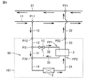
- FIG. 2 is a diagram representatively showing the configuration of the load devices 101-1 to 101-n of FIG. 1 and the flow of the heat medium.
- the air conditioning system 1000 includes a heat source device 201, a plurality of indoor heat exchangers 2, and a plurality of temperature adjustment devices 50.
- the heat source device 201 is configured to heat or cool the liquid medium.
- the plurality of indoor heat exchangers 2 are configured to be supplied with the liquid medium from the heat source device 201 and to perform heat exchange between the liquid medium and the air.
- the indoor heat exchanger 2 is a heat exchanger provided in the fan coil units FCU1 to FCUn in FIG.
- the plurality of temperature control devices 50 are respectively provided corresponding to the plurality of indoor heat exchangers 2 and configured to respectively adjust the temperature of the liquid medium supplied to the plurality of indoor heat exchangers 2.
- Each of the plurality of temperature control devices 50 heats between the inflow medium which is the liquid medium supplied to the corresponding indoor heat exchanger 2 and the outflow medium which is the liquid medium discharged from the corresponding indoor heat exchanger.
- the exchange amount is configured to be adjustable within a certain variable range.
- Each of the plurality of temperature control devices 50 responds by increasing the amount of heat exchange between the inflow medium and the outflow medium when the heat exchange capacity of the corresponding indoor heat exchanger 2 is larger than the indoor load. The heat exchange capacity of the indoor heat exchanger 2 is reduced.
- load device 101 includes a temperature control device 50 and an indoor heat exchanger 2.
- the end of the pipe 13 is a liquid inlet P12 to the load device 101, and the end of the pipe 23 is a liquid outlet P22 from the load device 101.
- the load device 101 is connected to the main piping 11 and 21 at the liquid inlet P12 and the liquid outlet P22.
- the liquid inlet P12 is connected to the pipe 12 branched from the main branch P11 in the main pipe 11 through which the heat medium of the air conditioning system flows.
- the liquid outlet P22 is connected to a pipe 22 joining the main junction P21 in the main pipe 21 through which the heat medium of the air conditioning system flows.
- the temperature control device 50 adjusts the temperature of the liquid medium that exchanges heat with air in the indoor heat exchanger 2 connected to the heat source device 201.
- the temperature adjustment device 50 includes a pipe FP1 (first pipe) and a pipe FP2 (second pipe) through which the liquid medium flows, a flow rate adjuster 1, a controller 51, and a temperature sensor 52.
- the pipe FP1 has a pipe 31 (first branch pipe) branched to two hands and pipes 32 and 33 (second branch pipe).
- the liquid-liquid heat exchanger 3 is configured to perform heat exchange between the liquid medium flowing through the pipes 32, 33 and the liquid medium flowing through the pipe FP2 among the liquid medium flowing through the pipe FP1.
- the flow rate adjustment device 1 is configured to change the flow rate of the liquid medium flowing through the pipes 32 and 33 and change the flow rate of the liquid medium flowing through the pipe 31.
- the flow rate adjusting device 1 is disposed at the branch P 31 of the pipe 32 and the pipe 31 and changes the ratio of the flow rate of the liquid medium flowing through the pipes 32 and 33 to the flow rate of the liquid medium flowing through the pipe 31 Flow distribution valve 1A.
- an electric three-way valve can be used as the flow rate distribution valve 1A.
- the flow rate distribution valve 1A may be disposed not at the branch portion P31 of the pipe 32 and the pipe 31, but at the junction P32 of the pipe 33 and the pipe 31. Unlike the switching valve, the flow control device 1 is configured to adjust the ratio of the flow rate of the liquid medium flowing through the pipes 32 and 33 to the flow rate of the liquid medium flowing through the pipe 31 stepwise or continuously. Ru.
- the pipe FP1 constitutes a flow path for supplying the liquid medium from the heat source device 201 to the indoor heat exchanger 2
- the pipe FP2 is a liquid medium from the indoor heat exchanger 2 to the heat source device 201. Construct a flow path to return the
- the pipe FP1 includes pipes 31, 32, and 33.
- the pipe FP2 includes the pipes 23 and 24.
- the pipe 32 branches from the pipe 13 which guides the heat medium from the liquid inlet P12, and supplies the heat medium to the first flow path of the liquid-liquid heat exchanger 3.
- the pipe 33 sends the heat medium flowing out of the first flow path of the liquid-liquid heat exchanger 3 to the pipe 14.
- the pipe 31 constitutes a flow path that bypasses the heat exchange path of the liquid-liquid heat exchanger 3.
- the piping FP1 and the piping 31 branch at a branch portion P31.
- the flow distribution valve 1A is disposed at the branch portion P31.
- the pipe 31 and the pipe 33 merge at the merging portion P32.
- the pipe 14 connects the junction P ⁇ b> 32 and the liquid inlet of the indoor heat exchanger 2.
- the pipe 24 connects the liquid outlet of the indoor heat exchanger 2 and the inlet of the second flow passage of the liquid-liquid heat exchanger 3.
- the second flow path is a flow path on the way back from the heat medium outlet of the indoor heat exchanger 2 to the heat source device 201.
- the pipe 23 connects the outlet of the second flow path of the liquid-liquid heat exchanger 3 and the liquid outlet P22.
- the flow rate distribution valve 1A adjusts the flow rate ratio at which the heat medium flowing from the pipe 13 into the branch portion P31 is distributed to the pipe 31 and the pipe 32.
- FIGS. 3 to 6 are views showing modifications of the flow rate adjustment device.
- FIG. 2 shows a configuration provided with a flow rate distributing valve 1A for changing the distribution ratio in the branch portion P31, but it may be modified as shown in FIGS.
- the control apparatus 51 and the temperature sensor 52 abbreviate
- the flow control device 1 includes a flow control valve 1B disposed in the pipe FP1.
- the flow rate adjustment valve 1 B is installed in the pipe 32.
- the flow rate adjustment valve 1B may be installed in the pipe 33.
- the flow rate adjustment valve 1B changes the ratio between the flow rate of the liquid medium flowing through the pipe FP1 and the flow rate of the liquid medium flowing through the pipe 31.
- a motor-operated valve whose opening degree can be adjusted can be used.
- the flow rate adjustment valve 1B may be disposed in the pipe 31 instead of being disposed in the pipe FP1.
- the flow rate adjustment device 1 includes the shutoff valve 1C disposed in the pipe FP1 and configured to operate intermittently.
- the shutoff valve 1 ⁇ / b> C can be operated intermittently and is installed in the pipe 32.
- the shutoff valve 1C may be installed in the pipe 33.
- the shutoff valve 1C may be disposed in the pipe 31 instead of being disposed in the pipe FP1.
- the control device 51 performs opening / closing control so that the shutoff valve 1C is intermittently repeated ON / OFF.
- the controller 51 changes the ratio between the flow rate of the liquid medium flowing through the pipe FP1 and the flow rate of the liquid medium flowing through the pipe 31 by changing the ON duty ratio of the shutoff valve 1C.
- the pipe FP1 includes a plurality of pipes FP3 (third branch pipes) connected in parallel with each other and performing heat exchange with the liquid medium flowing through the pipe FP2.
- the flow control device 1 includes a plurality of shutoff valves 1D provided to the plurality of pipes FP3.
- the liquid-liquid heat exchanger 3 is configured such that the amount of heat exchange differs for each of the plurality of pipes FP3.
- flow control device 1 of FIGS. 3 to 6 is illustrated as being installed in the pipe 32, any of them may be installed in the pipe 33.
- the heat medium delivered from the pump WP flows through the main piping 11. Part of the heat medium flowing through the main piping 11 flows from the liquid inlet P12 into the load device 101 via the piping 12 branched at the main branch portion P11.
- the heat medium flowing from the liquid inlet P12 flows through the pipe 13 and reaches the branch portion P31.
- the heat medium (cold water) that has reached the branch portion P31 is divided into the pipe 31 and the pipe 32, and flows.
- the temperature of the heat medium flowing through the pipe 32 is raised by heat exchange with the heat medium downstream of the indoor heat exchanger 2 in the liquid-liquid heat exchanger 3.
- the heat medium whose temperature has risen flows through the pipe 33 and reaches the merging portion P32.
- the temperature of the heat medium rises by mixing with the heat medium flowing through the pipe 33.
- the heat medium having reached the joining portion P32 flows through the pipe 14 and flows into the indoor heat exchanger 2.
- the heat medium that has flowed into the indoor heat exchanger 2 exchanges heat with air to cool the air conditioning target space.
- the temperature of the heat medium heat-exchanged with the air in the indoor heat exchanger 2 rises, and the heat medium flows through the pipe 24 and flows into the liquid-liquid heat exchanger 3.
- the heat medium flowing into the liquid-liquid heat exchanger 3 exchanges heat with the heat medium on the upstream side to lower the temperature.
- the heat medium whose temperature has dropped flows through the pipe 23 and reaches the liquid outlet P22.
- the heat medium that has reached the liquid outlet P22 flows out of the load device 101 and flows through the pipe 22.
- the heat medium flowing through the pipe 22 merges with the heat medium flowing through the main pipe 21 at the main junction P21.
- the heat medium joined in the main piping 21 flows to the heat source apparatus 201 of FIG. 1 and is cooled again.
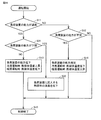
- FIG. 7 is a flow chart showing the operation of the heat source device 201 of the air conditioning system according to the first embodiment.
- heat medium temperature control of the heat source device 201 according to the first embodiment will be described according to the flowchart shown in FIG.
- control device 202 causes each of load devices 101-1 to 101-n installed at step S1 to exhibit maximum performance. Determine if there is.
- step S1 determines whether or not the load device 101 is exhibiting the maximum capability in step S1.
- the load device 101 shown in FIG. 2 exerts the maximum capacity when the heat medium flowing into the load device 101 flows into the indoor heat exchanger 2 while maintaining the temperature heated or cooled in the heat source device 201 as much as possible. . Therefore, a temperature sensor is installed in the pipe 14 which is the upstream portion of the indoor heat exchanger 2, and the measured temperature is compared with the water supply temperature of the heat source device 201.
- the determination may be made based on the flow rate in the pipe 32.
- the control device 51 controls the flow distribution valve 1A so that the distribution ratio to the primary side passage of the liquid-liquid heat exchanger 3 becomes 0%, all the heat medium (cold water) from the heat source device 201 is piping As it flows through 31, it is supplied to the indoor heat exchanger 2 as it is. In such a setting, the cooling capacity of the indoor heat exchanger 2 is set to the maximum.
- control device 202 reduces the capacity of the heat source device 201 in step S3.
- the control device 202 When the air conditioning system 1000 is performing a cooling operation, when none of the load devices 101-1 to 101-n is exhibiting the maximum capacity, the control device 202 generates heat to the heat source device 201. Increase the cooling temperature of the medium. By this, the capability of the heat source device 201 is reduced. When the cooling temperature of the heat medium rises, the refrigerant evaporation temperature of the heat source device 201 rises, so that the COP can be improved, and the energy saving effect can be exhibited.
- the control device 202 heats the heat medium to the heat source device 201 when all the load devices 101-1 to 101-n do not exhibit the maximum capacity. Reduce the temperature. By this, the capability of the heat source device 201 is reduced.
- the heating temperature of the heat medium is lowered, the condensation temperature of the heat source device 201 is lowered, so that COP (Coefficient Of Performance) can be improved, and an energy saving effect can be obtained.
- step S1 when there is at least one load device exhibiting the maximum capacity among the load devices 101-1 to 101-n (YES in S1), the controller 202 determines that the load device has the maximum capacity in step S2. Check whether there is a load device that is insufficient for air conditioning load even if
- the control device 202 determines whether the capacity of the load device 101 is excessive or insufficient in step S2.
- the load device 101 operates at a target temperature Tset instructed by the user using a remote control or the like.
- the difference between the target temperature Tset and the room temperature Ta measured by the temperature sensor 52 is below the specified value and the room temperature is lower than the target temperature in the case of cooling operation, and the room temperature is higher than the target temperature in the heating operation If the indoor load is too large, it can be judged that the capacity is excessive.
- the difference between the target temperature Tset and the room temperature Ta is equal to or higher than the specified value, and the room temperature is higher than the set temperature in the cooling operation, and lower than the target temperature in the heating operation (the room load is higher than the load device capacity) Is small) and it can be judged that the ability is insufficient.
- the controller 202 increases the capacity of the heat source device 201.
- the control device 202 lowers the cooling temperature of the heat medium with respect to the heat source device 201 when there is a load device whose capacity is insufficient even if it exhibits the maximum capacity. As a result, the capacity of the heat source device 201 is increased, and the control is ended (S5).
- the control device 202 causes the heat source device 201 to increase the heating temperature of the heat medium. As a result, the capacity of the heat source device 201 is increased, and the control is ended (S5).
- control device 202 When there is no load device whose capacity is insufficient even if the maximum capacity is exhibited in step S2 (NO in S2), the control device 202 does not instruct the heat source device 201 to change the operation state, and ends the control (S5 ).
- FIG. 8 is a flowchart showing the operation of the load device 101 of the air conditioning system according to the first embodiment.
- heat medium temperature control of the load device 101 according to the present invention will be described according to the flowchart shown in FIG.
- control device 202 determines whether the capacity of load device 101 is excessive or not in step S11. . Also in step S11, it is possible to determine whether the capacity of the load device 101 is excessive or not in the same manner as in step S2.
- control device 202 changes the amount of heat exchange of the temperature control device and causes the load device 101 to reduce the capacity.
- the controller 202 controls the temperature of the heat medium flowing into the indoor heat exchanger 2 into the load device 101. Raise This reduces the capacity of the load device 101.
- the flow distribution valve 1A of the load device 101 has a distribution ratio such that the flow rate of the heat medium flowing into the liquid-liquid heat exchanger 3 increases. Changed to increase the amount of heat exchange.
- the control device 202 determines that the capacity of the load device 101 is larger than the indoor load when the air conditioning system 1000 is in the heating operation, the control device 202 causes the load device 101 to generate the indoor heat exchanger 2. Reduce the temperature of the heat transfer medium flowing into the This increases the capacity of the load device 101. In order to reduce the temperature of the heat medium flowing into the indoor heat exchanger 2, the flow ratio distribution valve 1A of the load device 101 changes the distribution ratio so that the flow rate of the heat medium flowing into the liquid-liquid heat exchanger 3 decreases. And reduce the amount of heat exchange.
- step S11 when the control device 202 determines that the capacity of the load device 101 is not excessive (NO in S11), the control device 202 determines whether the capacity of the load device 101 is insufficient in step S12. Do.
- step S12 it is possible to determine whether the capacity of the load device 101 is insufficient in the same manner as in step S2.
- control device 202 causes the load device 101 to increase the capacity.
- the control device 202 determines that the capacity of the load device 101 is smaller than the indoor load when the air conditioning system 1000 is performing the cooling operation (YES in S12), the control device 202 performs the load device 101.
- the temperature of the heat medium flowing into the indoor heat exchanger 2 is reduced.
- the capacity of the load device 101 is increased (S14).
- the flow ratio distribution valve 1A of the load device 101 changes the distribution ratio so that the flow rate of the heat medium flowing into the liquid-liquid heat exchanger 3 decreases. And the control ends (S15).
- the control device 202 determines that the capacity of the load device 101 is smaller than the indoor load (YES in S12), the control device 202 sends the load device 101 The temperature of the heat medium flowing into the indoor heat exchanger 2 is raised. As a result, the capacity of the load device 101 is increased (S14). In order to raise the temperature of the heat medium flowing into the indoor heat exchanger 2, the flow ratio distribution valve 1A of the load device 101 changes the distribution ratio so that the flow rate of the heat medium flowing into the liquid-liquid heat exchanger 3 increases. And the control ends (S15).
- control device 202 determines that the capacity of the load device 101 is not insufficient in step S12 (NO in S12), the control device 202 ends the control without instructing the load device 101 to change the capacity. (S15).
- the load device does not exhibit the excess refrigeration capacity in order to achieve the target temperature. Therefore, the power consumption of the heat source device can be reduced. Furthermore, when all load devices are controlled to reduce their capacity, priority can be given to control of the water temperature of the heat source device, thereby enabling improvement in the COP of the heat source device, resulting in an energy saving effect. it can.
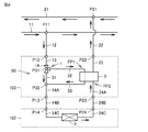
- FIG. 9 is a diagram showing the circuit configuration of the load device 102 and the relay device 103 according to the second embodiment and the flow of the heat medium.
- each component included in the load device 101 according to the first embodiment is divided into the load device 102 and the relay device 103 and accommodated.
- the heat medium flows in from the liquid inlet P14 and flows out from the liquid outlet P24.
- the load device 102 includes the indoor heat exchanger 2, a pipe 14C connecting the liquid inlet P14 and the indoor heat exchanger 2, and a pipe 24C connecting the indoor heat exchanger 2 and the liquid outlet P24.
- the relay device 103 includes a liquid-liquid heat exchanger 3 and a temperature control device 50.
- the relay device 103 is disposed between the main pipes 11 and 21 of the liquid medium and the indoor heat exchanger 2.
- the relay device 103 may include one of the temperature control devices shown in FIGS. 3 to 6 and one of the temperature control devices shown in FIG. 13 later, instead of the temperature control device 50.
- the relay device 103 further includes a first path from the liquid inlet P12 to the liquid outlet P13, and a second path from the liquid inlet P23 to the liquid outlet P22.
- the first path connects the pipe 13 connecting the liquid inlet P12 to the branch P31, the pipe 31 connecting the branch P31 to the junction P32, and the branch P31 to the liquid-liquid heat exchanger 3 It includes a pipe 32, a pipe 33 connecting the liquid-liquid heat exchanger 3 and the merging portion P32, and a pipe 14A connecting the merging portion P32 and the liquid outlet P13.
- the second path includes a pipe 24A connecting the liquid inlet P23 and the liquid-liquid heat exchanger 3, and a pipe 23 connecting the liquid-liquid heat exchanger 3 and the liquid outlet P22.
- the relay device 103 includes a flow distribution valve 1A that adjusts the flow rate at which the heat medium flowing from the pipe 13 into the branch portion P31 branches to the pipe 31 and the pipe 32.
- FIG. 9 shows a configuration in which the flow control device 1 is provided with the flow distribution valve 1A at the branch portion P31, it may be modified as shown in FIG. 3 to FIG. Further, although the flow rate adjusting device 1 of FIGS. 9 and 3 to 6 is illustrated as being installed in the pipe 32, any of them may be installed in the pipe 33.
- the relay device 103 is connected to the heat source device side at two points, the liquid inlet P12 and the liquid outlet P22.
- the liquid inlet P12 is connected to the main pipe 11 through which the heat medium of the air conditioning system flows, and the pipe 12 branched at the main branch portion P11.
- the liquid outlet P22 is connected to a pipe 22 which joins the main junction P21 of the main pipe 21 through which the heat medium of the air conditioning system flows.
- the load device 102 is connected at two points, the relay device 103, the liquid inlet P14, and the liquid outlet P24.
- the liquid inlet P14 is connected to the liquid outlet P13 of the relay device 103 by a pipe 14B.
- the liquid outlet P24 is connected to the liquid inlet P23 of the relay device 103 by a pipe 24B.
- the flow of the heat medium will be described with reference to FIG. Arrows shown in FIG. 9 indicate the flow direction of the heat medium.
- the heat medium delivered from the pump WP of FIG. Part of the heat medium flowing through the main piping 11 flows from the liquid inlet P12 into the relay device 103 via the piping 12 branched at the main branch portion P11.
- the heat medium flowing from the liquid inlet P12 flows through the pipe 13 and reaches the branch portion P31.
- the heat medium (cold water) that has reached the branch portion P31 is divided into the pipe 31 and the pipe 32, and flows.
- the temperature of the heat medium flowing through the pipe 32 is raised by heat exchange with the heat medium downstream of the indoor heat exchanger 2 in the liquid-liquid heat exchanger 3.
- the heat medium whose temperature has risen flows through the pipe 33 and reaches the merging portion P32.
- the temperature of the heat medium rises by mixing with the heat medium flowing through the pipe 33.
- the heat medium that has reached the merging portion P32 flows through the pipe 14A and reaches the liquid outlet P13.
- the heat medium that has reached the liquid outlet P13 flows out from the relay device 103 and flows through the pipe 14B.
- the heat medium flowing through the pipe 14B flows into the load device 102 from the liquid inlet P14.
- the heat medium flowing into the load device 102 flows through the pipe 14 C and flows into the indoor heat exchanger 2.
- the heat medium that has flowed into the indoor heat exchanger 2 exchanges heat with air to cool the air conditioning target space.
- the temperature of the heat medium heat-exchanged with the air in the indoor heat exchanger 2 rises, and flows through the pipe 24C to reach the liquid outlet P24.
- the heat medium having reached the liquid outlet P24 flows out of the load device 102 and flows through the pipe 24B.
- the heat medium flowing through the pipe 24 B reaches the liquid inlet P 23 of the relay device 103.
- the refrigerant that has reached the liquid inlet P23 flows through the pipe 24A and flows into the liquid-liquid heat exchanger 3.
- the temperature of the heat medium flowing into the liquid-liquid heat exchanger 3 is lowered by heat exchange with the heat medium on the upstream side.
- the heat medium whose temperature has dropped flows through the pipe 23 and reaches the liquid outlet P22.
- the heat medium that has reached the liquid outlet P22 flows out of the relay device 103 and flows through the pipe 22.
- the heat medium flowing through the pipe 22 merges with the heat medium flowing through the main pipe 21 at the main junction P21.
- the heat medium joined in the main piping 21 flows to the heat source apparatus 201 of FIG. 1 and is cooled again.
- the configuration of the second embodiment shown in FIG. 9 is the same as a general air conditioning system when the relay device 103 is removed.
- the relay device 103 in the general air conditioning system, the relay device 103 is connected between the pipe 12 and the liquid inlet P14 and between the pipe 22 and the liquid outlet P24. That is, even in a building where the air conditioning system has already been introduced, if the liquid inlet P14 is removed from the piping 12, the liquid outlet P24 is removed from the piping 22, and the relay device 103 is inserted, energy saving of the existing air conditioning system. You can easily improve the general air conditioning system.
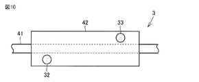
- FIG. 10 is a front view of a configuration example of the liquid-liquid heat exchanger 3.
- FIG. 11 is a side view of a configuration example of the liquid-liquid heat exchanger 3.
- FIG. 12 is a perspective view of a configuration example of the liquid-liquid heat exchanger 3.
- one of the components of the liquid-liquid heat exchanger 3 is the existing pipe 41.
- the existing pipe 41 is installed so as to cover the existing pipe 41 from the periphery with a cylindrical component 42 having an inner diameter larger than the existing pipe 41 as shown in FIGS.
- heat exchange can be performed by filling the inside and the outside of the existing pipe with the heat medium.
- one of the heat exchangers can be used as an existing state, the introduction to the existing air conditioning system can be further facilitated.
- FIG. 13 is a diagram showing the circuit configuration of the load device according to the third embodiment and the flow of the heat medium.
- load device 104 includes a temperature control device 50F and an indoor heat exchanger 2.
- the temperature control device 50F includes a pipe FP1 and a pipe FP2 through which the liquid medium flows, the liquid-liquid heat exchanger 3, a pipe 31 which branches from the pipe FP1 and bypasses the liquid-liquid heat exchanger 3, the flow rate adjuster 1 Equipped with
- the flow control device 1 includes a flow distribution valve 1A.
- the pipe FP1A includes the pipes 32, 33.
- the pipe FP 2 A includes the pipes 13 and 14.
- the control device 51 and the temperature sensor 52 are also disposed as in FIG.
- the pipe 13 leads the heat medium to the liquid-liquid heat exchanger 3 from the liquid inlet P12.
- the pipe 14 connects the liquid-liquid heat exchanger 3 and the indoor heat exchanger 2.
- the pipe 24 connects the indoor heat exchanger 2 and the branch portion P31.
- the pipe 31 is a main circuit that connects the branch portion P31 and the merging portion P32.
- the pipe 32 connects the branch portion P31 and the liquid-liquid heat exchanger 3.
- the pipe 33 connects the liquid-liquid heat exchanger 3 and the junction P32.
- the pipe 23 connects the junction P32 and the liquid outlet P22.
- the load device 104 includes a flow distribution valve 1A that adjusts the flow rate of the heat medium flowing from the pipe 24 to the branch portion P31 and distributed to the pipe 31 and the pipe 32.
- FIG. 13 shows a configuration in which the flow distribution valve 1A is provided at the branch portion P31, the configuration may be modified in the same manner as the example in FIGS.
- the flow control devices of FIGS. 3 to 6 are illustrated as being installed in the pipe 32, they may be installed in the pipe 33.
- the load device 104 is connected at two points, that is, the main piping 11, 21 from the heat source device, the liquid inlet P12, and the liquid outlet P22.
- the liquid inlet P12 is connected to the pipe 12 branched from the main branch P11 of the main pipe 11 through which the heat medium of the air conditioning system flows.
- the liquid outlet P22 is connected to the main piping 21 through which the heat medium of the air conditioning system flows, and the piping 22 joined at the main junction P21.
- the flow of the heat medium will be described with reference to FIG. Arrows shown in FIG. 13 indicate the flow direction of the heat medium.
- the heat medium (cold water) flowing in from the liquid inlet P12 flows through the pipe 13 and flows into the liquid-liquid heat exchanger 3, and exchanges heat with the heat medium downstream of the indoor heat exchanger 2, and the temperature rises. .
- the heat medium whose temperature has risen flows through the pipe 14 and flows into the indoor heat exchanger 2.
- the heat medium that has flowed into the indoor heat exchanger 2 exchanges heat with air to cool the air conditioning target space.
- the temperature of the heat medium heat-exchanged with the air in the indoor heat exchanger 2 rises, and reaches the branch portion P31.
- the heat medium that has reached the branch portion P31 branches and flows through the pipe 31 and the pipe 32.
- the heat medium flowing through the pipe 32 exchanges heat with the heat medium on the upstream side in the liquid-liquid heat exchanger 3 to lower the temperature.
- the heat medium whose temperature has been lowered flows through the pipe 33 and reaches the merging portion P32.
- the heat medium flowing through the pipe 31 reaches the merging portion P32, mixes with the heat medium flowing through the pipe 33, and the temperature decreases.
- the heat medium having reached the merging portion P32 flows through the pipe 23 and reaches the liquid outlet P22.
- the heat medium that has reached the liquid outlet P22 flows out of the load device 104 and flows through the piping 22.
- the heat medium flowing through the pipe 22 merges with the heat medium flowing through the main pipe 21 at the main junction P21.
- the heat medium joined in the main piping 21 flows to the heat source apparatus 201 of FIG. 1 and is cooled again.
- FIG. 14 is a diagram illustrating the circuit configuration of the load device 102 and the relay device 105 according to the fourth embodiment and the flow of a heat medium.
- the components included in the load device 104 according to the third embodiment are divided into two devices of a load device 102 and a relay device 105 and accommodated.
- the configuration of load device 102 is the same as in the second and third embodiments, and therefore the description will not be repeated here.
- the relay device 105 includes a liquid-liquid heat exchanger 3 and a temperature control device 50.
- the relay device 105 is disposed between the main pipes 11 and 21 of the liquid medium and the indoor heat exchanger 2.
- the relay device 105 further includes a first path from the liquid inlet P12 to the liquid outlet P13, and a second path from the liquid inlet P23 to the liquid outlet P22.
- the first path includes a pipe 13 connecting the liquid inlet P12 and the liquid-liquid heat exchanger 3 and a pipe 14A connecting the liquid-liquid heat exchanger 3 and the liquid outlet P13.
- the second path connects the pipe 24A connecting the liquid inlet P23 and the branch P31, the pipe 31 connecting the branch P31 and the junction P32, and the branch P31 and the liquid-liquid heat exchanger 3 It includes a pipe 32, a pipe 33 connecting the liquid-liquid heat exchanger 3 and the merging portion P32, and a pipe 23 connecting the merging portion P32 and the liquid outlet P22.
- the relay device 105 includes a flow distribution valve 1A that adjusts the flow rate at which the heat medium flowing from the pipe 24A to the branch portion P31 branches to the pipe 31 and the pipe 32.
- FIG. 14 shows the configuration in which the flow distribution valve 1A is provided at the branch portion P31, it may be modified as shown in FIG. 3 to FIG.
- the flow control devices of FIGS. 3 to 6 are illustrated as being installed in the pipe 32, they may be installed in the pipe 33.
- the relay device 105 is connected at two locations, the heat source device side, the liquid inlet P12, and the liquid outlet P22.
- the liquid inlet P12 is connected to the main pipe 11 through which the heat medium of the air conditioning system flows, and the pipe 12 branched at the main branch portion P11.
- the liquid outlet P22 is connected to a pipe 22 which joins the main junction P21 of the main pipe 21 through which the heat medium of the air conditioning system flows.
- the load device 102 is connected at two points, the relay device 105, the liquid inlet P14, and the liquid outlet P24.
- the liquid inlet P14 is connected to the liquid outlet P13 of the relay device 105 by a pipe 14B.
- the liquid outlet P24 is connected to the liquid inlet P23 of the relay device 105 by a pipe 24B.
- the flow of the heat medium will be described with reference to FIG. Arrows shown in FIG. 14 indicate the flow direction of the heat medium.
- the heat medium delivered from the pump WP of FIG. A part of the heat medium flowing through the main piping 11 branches at the main branch portion P11 and flows into the relay device 105 from the liquid inlet P12 via the piping 12.
- the heat medium (cold water) flowing in from the liquid inlet P12 flows through the pipe 13 and flows into the liquid-liquid heat exchanger 3, and exchanges heat with the heat medium downstream of the indoor heat exchanger 2, and the temperature rises. .
- the heat medium whose temperature has risen flows through the pipe 14A and reaches the liquid outlet P13.
- the heat medium that has reached the liquid outlet P13 flows out from the relay device 105 and flows through the pipe 14B.
- the heat medium flowing through the pipe 14B flows into the load device 102 from the liquid inlet P14.
- the heat medium flowing into the load device 102 flows through the pipe 14 C and flows into the indoor heat exchanger 2.
- the heat medium that has flowed into the indoor heat exchanger 2 exchanges heat with air to cool the air conditioning target space.
- the temperature of the heat medium heat-exchanged with the air in the indoor heat exchanger 2 rises, and flows through the pipe 24C to reach the liquid outlet P24.
- the heat medium that has reached the liquid outlet P24 flows out of the load device 102 and flows through the pipe 24B.
- the heat medium flowing through the pipe 24 B reaches the liquid inlet P 23 of the relay device 103.
- the heat medium having reached the liquid inlet P23 flows through the pipe 24A and reaches the branch portion P31.
- the heat medium that has reached the branch portion P31 branches and flows through the pipe 31 and the pipe 32.
- the heat medium flowing through the pipe 32 exchanges heat with the heat medium on the upstream side of the indoor heat exchanger 2 in the liquid-liquid heat exchanger 3, and the temperature decreases.
- the heat medium whose temperature has been lowered flows through the pipe 33 and reaches the merging portion P32.
- the heat medium flowing through the pipe 31 reaches the merging portion P32, mixes with the heat medium flowing through the pipe 33, and the temperature decreases.
- the heat medium having reached the merging portion P32 flows through the pipe 23 and reaches the liquid outlet P22.
- the heat medium that has reached the liquid outlet P22 flows out of the relay device 105 and flows through the pipe 22.
- the heat medium flowing through the pipe 22 merges with the heat medium flowing through the main pipe 21 at the main junction P21.
- the heat medium joined in the main piping 21 flows to the heat source apparatus 201 of FIG. 1 and is cooled again.
- the temperature of the heat medium supplied to the indoor heat exchanger 2 can be changed by adding the relay device 105 to the existing air conditioning system.
- FIG. 15 is a diagram showing the circuit configuration of the load device 102 and the relay device 106 according to the fifth embodiment and the flow of the heat medium.
- the liquid medium is supplied from the heat source device 201 to the plurality of load devices 101-1 to 101-n through the trunk piping 11 and returned to the heat source device 201 through the trunk piping 21.
- the pipe FP1B and the pipe FP2B of the relay device 106 respectively correspond to the pipe FP1 and the pipe FP2 of the relay device 103 of the second embodiment shown in FIG.
- the pipe FP2B is a part of the main line pipe 21.
- the pipe FP1B branches from the main line 11 and constitutes a flow path for supplying a liquid medium to the indoor heat exchanger 2.
- the pipe FP1B may be part of the main pipe 11, and the pipe FP2B may be part of the pipe 22 for returning the liquid medium from the indoor heat exchanger 2 to the main pipe 21. Since the configuration of load device 102 is the same as that of the second embodiment, the description will not be repeated here.
- the relay device 106 includes the liquid-liquid heat exchanger 3, a first path from the liquid inlet P12 to the liquid outlet P13, and a second path from the liquid inlet P23 to the liquid outlet P22.
- the first path connects the pipe 13 connecting the liquid inlet P12 to the branch P31, the pipe 31 connecting the branch P31 to the junction P32, and the branch P31 to the liquid-liquid heat exchanger 3 It includes a pipe 32, a pipe 33 connecting the liquid-liquid heat exchanger 3 and the merging portion P32, and a pipe 14A connecting the merging portion P32 and the liquid outlet P13.
- the second path includes a main line pipe 21A connecting the liquid inlet P23 and the liquid-liquid heat exchanger 3 and a main line 21B connecting the liquid-liquid heat exchanger 3 and the liquid outlet P22.
- the relay device 106 includes a flow distribution valve 1A that adjusts the flow rate at which the heat medium flowing from the pipe 13 into the branch portion P31 branches to the pipe 31 and the pipe 32.
- FIG. 15 shows a configuration in which the flow distribution valve 1A is provided at the branch portion P31, it may be modified as shown in FIG. 3 to FIG.
- the flow control devices of FIGS. 3 to 6 are illustrated as being installed in the pipe 32, they may be installed in the pipe 33.
- the relay device 106 is connected to the main piping of the heat medium of the air conditioning system at three locations: a fluid inlet P12, a fluid inlet P23, and a fluid outlet P22.
- the liquid inlet P12 is connected to the main pipe 11 through which the heat medium of the air conditioning system flows, and the pipe 12 branched at the main branch portion P11.
- the relay device 106 is inserted into the trunk piping 21 halfway. That is, the liquid inlet P23 is connected to the upstream side of the main line 21 and the liquid outlet P22 is connected to the downstream side of the main line 21.
- the liquid inlet P14 of the loading device 102 is connected to the liquid outlet P13 of the relay device 106 by a pipe 14B. Further, the liquid outlet P ⁇ b> 24 of the load device 102 is connected by the main junction P ⁇ b> 21 of the main line pipe 21 and the pipe 22.
- the flow of the heat medium will be described with reference to FIG. Arrows shown in FIG. 15 indicate the flow direction of the heat medium.
- the heat medium delivered from the pump WP of FIG. Part of the heat medium flowing through the main piping 11 flows from the liquid inlet P12 into the relay device 106 via the piping 12 branched at the main branch portion P11.
- the heat medium flowing from the liquid inlet P12 flows through the pipe 13 and reaches the branch portion P31. Part of the heat medium that has reached the branch portion P31 flows through the pipe 31, and the remaining portion flows through the pipe 32.
- the heat medium flowing through the pipe 32 exchanges heat with the heat medium on the main pipe 21 side by the liquid-liquid heat exchanger 3, and the temperature rises.
- the heat medium whose temperature has risen flows through the pipe 33 and reaches the merging portion P32.
- the heat medium flowing through the pipe 31 reaches the junction P32, mixes with the heat medium flowing through the pipe 33, and the temperature rises.
- the heat medium merged at the merging portion P32 flows through the pipe 14A and reaches the liquid outlet P13.
- the heat medium that has reached the liquid outlet P13 flows out of the relay device 106 and flows through the pipe 14B.
- the heat medium flowing through the pipe 14B flows into the load device 102 from the liquid inlet P14.
- the inflowing heat medium flows through the pipe 14 C and flows into the indoor heat exchanger 2.
- the heat medium that has flowed into the indoor heat exchanger 2 exchanges heat with air to cool the air conditioning target space.
- the temperature of the heat medium heat-exchanged with the air in the indoor heat exchanger 2 rises, and flows through the pipe 24C to reach the liquid outlet P24.
- the heat medium having reached the liquid outlet P 24 flows out of the load device 102 and flows through the pipe 22.
- the heat medium flowing through the pipe 22 merges with the heat medium flowing through the main pipe 21 at the main junction P21.
- the combined heat medium flows through the main outlet pipe and reaches the liquid inlet P23 of the relay device 106.
- the refrigerant that has reached the liquid inlet P23 flows through the pipe 21A and flows into the liquid-liquid heat exchanger 3.
- the heat medium flowing into the liquid-liquid heat exchanger 3 exchanges heat with the heat medium of the pipe FP1B, and the temperature drops.
- the heat medium whose temperature has been lowered flows through the pipe 21B and reaches the liquid outlet P22.
- the heat medium that has reached the liquid outlet P22 flows through the main piping 21 and flows to the heat source device 201 of FIG. 1 to be cooled again.
- the energy saving property of the existing air conditioning system can also be improved by inserting the relay device into the trunk piping.
- FIG. 16 is a diagram showing the circuit configuration of the load device 102 and the relay device 107 and the flow of the heat medium according to the sixth embodiment.
- a relay device 107 when the air conditioning system has a plurality of load devices 102, a relay device 107 is used which relays the trunk piping and the plurality of load devices.
- Relay apparatus 107 has a form in which relay apparatus 103 according to the second embodiment is integrated.
- the liquid medium is supplied from the heat source device 201 to the plurality of indoor heat exchangers 2 through the main piping.
- the relay device 107 is disposed between the main line pipes 11 and 21 of the liquid medium and the plurality of indoor heat exchangers 2, and a plurality of temperature adjustments respectively corresponding to the plurality of indoor heat exchangers 2.
- An apparatus 50 is provided.
- the relay device 107 may include any of the temperature control devices shown in FIGS. 3 to 6 and 13 instead of the temperature control device 50.
- the configuration of the part corresponding to the relay device 103 and the flow of the heat medium have been described in the second embodiment, so the description will not be repeated here.
- the configuration of the relay device 103 of FIG. 9 is employed for heat exchange of the liquid-liquid heat exchanger 3 in FIG. 16, the configuration of the relay device 105 of FIG. 14 may be employed.
- the relay device since a plurality of relay devices are integrated, the relay device can not be provided near the individual load devices 102, and the relay device can be secured in another place. It becomes possible to arrange.
- FIG. 17 is a diagram showing the circuit configuration of the load device 102 and the relay device 108 and the flow of the heat medium according to a modification of the sixth embodiment.
- Embodiment 6 uses the relay apparatus 108 which relays trunk piping and several load apparatuses, when an air conditioning system has several load apparatuses 102.
- the heat medium flowing through the pipe 32 connected to the branch portion P31 of the relay device 107 according to the sixth embodiment is connected to the liquid-liquid heat exchanger 3 of another system and exchanges heat.
- the heat medium subjected to heat exchange flows through the pipe 33 and merges with the heat medium flowing through the pipe 31 at the merging portion P32 of the original system.
- the configuration and the flow of the heat medium are the same as in the sixth embodiment.
- the configuration of the relay unit 103 of FIG. 9 is employed for heat exchange of the liquid-liquid heat exchanger 3 in FIG. 17, the configuration of the relay unit 105 of FIG. 14 may be employed.
- FIG. 18 is a diagram showing a circuit configuration of a load device according to a seventh embodiment and a flow of a heat medium.
- a configuration for adjusting the flow rate of the heat medium flowing in is added to the load devices realized in the first to sixth embodiments. The addition of this configuration makes it possible to adjust the flow rate at the same time as adjusting the temperature of the heat medium, and to realize simultaneous adjustment of temperature and humidity of the space to be air conditioned.
- the air conditioning system includes a flow distribution valve 51A that adjusts the flow rate of the heat medium flowing to the indoor heat exchanger 2.
- the liquid medium is supplied from the heat source device 201 to the plurality of load devices 101-1 to 101-n through the main pipes 11, 21.
- FIG. 19 is a flowchart for explaining a modification in which flow control of the load device is added to the control of FIG. 8.
- the processes of steps S31 and S32 are added to the flowchart of FIG. 8 in the flowchart of FIG.
- control device 202 determines whether the capacity of load device 101 is excessive or not in step S11.
- step S31 determines in step S31 whether the capacity of the load device 101 is the lower limit in step S31. If the capacity of the load device 101 is the lower limit (YES in S31), the control device 202 reduces the flow rate of the heat medium flowing into the load device 101. On the other hand, when the capacity of the load device 101 is not the lower limit, the controller 202 reduces the capacity of the load device 101.
- FIG. 18 shows the configuration in which the flow distribution valve 51A is installed at the main branch portion P11 of the main line 11.
- a flow control valve 51B disposed in the pipe 12 between the pipe FP1 and the main pipe 11 is further provided.
- the flow rate adjustment valve 51 B may be disposed in the pipe 22 between the pipe FP 2 and the main pipe 21.
- a shutoff valve 51C disposed on the pipe 12 between the pipe FP1 and the main pipe 11 and configured to operate intermittently is further provided.
- the shutoff valve 51C may be disposed in the pipe 22 between the pipe FP2 and the main pipe 21.
- a plurality of pipes FP4 (fourth branch pipes) disposed between the pipe FP1 and the main pipe 11 and connected in parallel to one another and a plurality of pipes FP4
- a plurality of shutoff valves 51D provided respectively are further provided.
- the plurality of pipes FP4 and the plurality of shutoff valves 51D may be disposed between the pipe FP2 and the main pipe 21.
- FIGS. 20-22 are illustrated as being installed in the pipe 12, they may be installed in any of the pipes 13, 14, 22-24.
- FIG. 18 and FIGS. 20 to 22 show an example in which the flow control device is added to the load device 101 of the first embodiment, a flow control device similar to that of the second to sixth embodiments is disposed. May be
- FIG. 23 is a diagram showing the circuit configuration of the load device 109 according to the eighth embodiment and the flow of the heat medium.
- the load device 109 circulates the heat medium in the order of the pump 4, the branch portion P31, the junction P32, the indoor heat exchanger 2, the liquid-liquid heat exchanger 3, and the third heat exchanger 5. It includes a circuit and a flow path that flows from the main piping 11 to the main piping 21 via the liquid inlet P12, the third heat exchanger 5, and the liquid outlet P22.
- the circuit starting from the pump 4 includes a pipe 13 connecting the pump 4 and the branch P31, a pipe 31 connecting the branch P31 and the junction P32, a branch P31 and the liquid-liquid heat exchanger 3 , The pipe 33 connecting the liquid-liquid heat exchanger 3 and the junction P32, the pipe 14 connecting the junction P32 and the indoor heat exchanger 2, the indoor heat exchanger 2 and the liquid -Piping 24 connecting the liquid heat exchanger 3, piping 23 connecting the liquid-liquid heat exchanger 3 and the third heat exchanger 5, piping 34 connecting the third heat exchanger 5 and the pump And.
- the flow path starting from the liquid inlet P12 includes a pipe 35 connecting the liquid inlet P12 and the third heat exchanger 5 and a pipe 36 connecting the third heat exchanger 5 and the liquid outlet P22.
- the load device 109 includes a flow rate adjustment device that adjusts the flow rate at which the heat medium flowing from the pipe 13 into the branch portion P31 branches to the pipe 31 and the pipe 32.
- FIG. 23 shows the configuration in which the flow distribution valve 1A is provided at the branch portion P31, it may be modified as shown in FIGS.
- the flow control devices of FIGS. 3 to 6 are illustrated as being installed in the pipe 32, they may be installed in the pipe 33.
- FIG. 23 shows the same configuration as that of FIG. 2 of the first embodiment in heat exchange of the liquid-liquid heat exchanger 3, it may be similar to that of FIG. 13 of the third embodiment.
- the load device 109 is connected to the main piping 11 and 21 of the air conditioning system at two points, the liquid inlet P12 and the liquid outlet P22.
- the liquid inlet P12 is connected to the pipe 12 branched from the main branch P11 in the main pipe 11 through which the heat medium of the air conditioning system flows.
- the liquid outlet P22 is connected to the piping 22 branched from the main junction P21 in the main piping 21 through which the heat medium of the air conditioning system flows.
- the heat medium delivered from the pump WP of FIG. Part of the heat medium flowing through the main piping 11 reaches the liquid inlet P12 via the piping 12 branched at the main branch portion P11.
- the heat medium that has reached the liquid inlet P12 flows through the pipe 35 and flows into the third heat exchanger 5.
- the heat medium that has flowed into the third heat exchanger 5 exchanges heat with the use side heat medium of the load device to cool the use side heat medium.
- the heat medium heat-exchanged with the use-side heat medium in the third heat exchanger 5 flows through the pipe 36 and reaches the liquid outlet P22.
- the heat medium that has reached the liquid outlet P22 flows through the pipe 22 and flows out of the load device 109.
- the heat medium flowing through the pipe 22 merges with the heat medium flowing through the main pipe 21 at the main junction P21.
- the heat medium joined in the main piping 21 flows to the heat source apparatus 201 of FIG. 1 and is cooled again.
- FIG. 23 shows an example in which the heat medium flowing through the main pipes 11, 21 is water or brine
- the heat source apparatus of the eighth embodiment may be a refrigeration cycle using a gas refrigerant.
- the refrigerant is transported not by the pump WP but by the compressor, and the expansion device installed outside of the main line piping 11, 12, 35 or shown in the drawing becomes a low pressure refrigerant and flows into the third heat exchanger 5 to be used Heat exchange with the side heat medium.
- the heat medium delivered from the pump 4 flows through the pipe 13 and reaches the branch portion P31.
- the heat medium that has reached the branch portion P31 is divided into the pipe 31 and the pipe 32, and flows.
- the heat medium of the pipe FP1 flowing through the pipe 32 exchanges heat with the heat medium of the pipe FP2 on the downstream side of the indoor heat exchanger 2 by the liquid-liquid heat exchanger 3, and the temperature rises.
- the heat medium whose temperature has risen flows through the pipe 33 and reaches the merging portion P32.
- the remaining heat medium flowing through the pipe 31 reaches the junction P32, mixes with the heat medium flowing through the pipe 33, and the temperature rises.
- the heat medium that has reached the merging portion P32 flows through the pipe 14 and flows into the indoor heat exchanger 2.
- the heat medium flowing into the indoor heat exchanger 2 cools the air-conditioned space by heat exchange with air.
- the temperature of the heat medium heat-exchanged with air in the indoor heat exchanger 2 rises, and flows into the liquid-liquid heat exchanger 3 through the pipe 24.
- the temperature of the heat medium flowing into the liquid-liquid heat exchanger 3 is reduced by heat exchange with the heat medium of the upstream pipe FP1.
- the heat medium whose temperature has been lowered flows through the pipe 23 and flows into the third heat exchanger 5.
- the heat medium flowing into the third heat exchanger 5 exchanges heat with the heat medium flowing through the pipe 35 branched from the main pipe 11, and the temperature drops.
- the heat medium whose temperature has been lowered reaches the pump 4 via the pipe 34 and is again delivered to the pipe 13.
- FIG. 24 is a flowchart for explaining a modification in which control of a pump is added to the control of FIG. 7.
- the capacity adjustment by the temperature change of the load device 101 and the heat source device 201 is carried out, both have lower limit in capacity decrease, so when the air conditioning load becomes lower than the lower limit There is a problem that the user feels uncomfortable due to waste or intermittent operation of air conditioning.
- control device 202 determines in step S1 whether each of load devices 101-1 to 101-n is exhibiting the maximum capacity. When all of the load devices 101-1 to 101-n do not exhibit the maximum capacity (NO in S1), in step S21, the control device 202 determines whether the capacity of the heat source device 201 is the lower limit.
- the control device 202 reduces the flow rate of the pump WP in step S22, and the control ends in step S5. Since the reduction of the flow rate of the pump WP can further reduce the capacity of the air conditioning system, the power consumption when the air conditioning load is low can be improved and the user's discomfort can be reduced.
- step S3 the control apparatus 202 controls the heat source apparatus 201 so that the capacity of the heat source apparatus 201 is reduced, and the control ends in step S5. .
- steps S2 and S4 are performed.
- the processes of step S2 and step S4 have been described with reference to FIG. 7, so the description will not be repeated here.
- FIG. 23 shows the configuration in which the configuration of the eighth embodiment is accommodated in a single load device 109, it may be divided into the load device 110 and the relay device 111 as shown in FIG. At this time, as shown in FIG. 16 shown in the sixth embodiment, the relay apparatus 111 may accommodate multiple relay apparatuses in one relay apparatus.
- the pump 4 when the pump 4 has a variable rotational speed, the pump 4 has a flow rate adjusting function, so that temperature and humidity simultaneous adjustment of the space to be air-conditioned is realized as in the seventh embodiment.
- the circuit shown in FIG. 23 is provided with a device for adjusting the flow rate of the heat medium flowing to the third heat exchanger 5, the range in which the temperature and humidity of the space to be air conditioned can be adjusted can be expanded.
- the configuration is the same as in FIG. 18 of the seventh embodiment, in which the flow distribution valve 51A is installed at the main branch P11 of the trunk pipe 11, the flow adjustment valve 51B is installed in the pipe 12 as shown in FIG.
- a configuration in which the shutoff valve 51C capable of intermittent operation is installed in the pipe 12 may be configured as in FIG. 22 where a plurality of pipes 12 are branched in parallel to install the shutoff valve 51D in each pipe
- the adjusting device may be installed in any of the pipes 12, 22, 35, 36.
- FIG. 26 is a diagram showing a circuit configuration of a load device according to a ninth embodiment and a flow of a heat medium.
- the load device 112 shown in FIG. 26 includes a heater 6 in place of the liquid-liquid heat exchanger 3 in the configuration of the load device 101 of the first embodiment shown in FIG.
- the piping 24 connects the indoor heat exchanger 2 and the liquid outlet P22 by the configuration change.
- the other configurations and the flow of the heat medium are the same as in the first embodiment, and therefore the description will not be repeated.
- the configuration may be simplified like the heater 7 of the load device 113 shown in FIG. In this configuration, power consumption by the heater is required, so that the energy saving effect is reduced, but the discomfort suppressing effect due to the humidity decrease in the indoor space can be expected sufficiently.
- the configuration for adjusting the flow rate is a configuration in which the flow distribution valve 51A is installed at the main branch P11 of the main pipe 11 as in FIG. 18 of the seventh embodiment, and a configuration in which the flow control valve 51B is installed in the piping 12 as in FIG.
- the shutoff valve 51C capable of intermittent operation may be installed in the pipe 12.
- a plurality of pipes 12 may be branched in parallel to install the shutoff valve 51D in each pipe.
- any of these adjustment mechanisms may be installed in any of the pipes 13, 14, 22, 24.
- the above embodiments are also applicable to a refrigeration cycle apparatus.
- the refrigeration cycle apparatus is provided with a relay apparatus, a heat source apparatus, or a load apparatus and a heat source apparatus, and is typically an air conditioner, but is a showcase, a refrigerator, a freezer, a refrigerated warehouse, a freezer warehouse, etc. Can also be mentioned as an example of the refrigeration cycle apparatus.
- 1 flow rate adjusting device 1A, 51A flow rate distributing valve, 1B, 51B flow rate adjusting valve, 1C, 1D, 51C, 51D shut off valve, 2 indoor heat exchanger, 3 liquid-liquid heat exchanger, 4, WP pump, 5 heat Exchanger, 6, 7 heater, 11, 21, 21, 21A, 21B Main piping, 12 to 14, 14A to 14C, 22 to 24, 24A to 24C, 31 to 36, 41, FP1B, FP1, FP2, FP3, FP4 piping , 42 parts, 50, 50 F temperature control device, 51, 202 control device, 52 temperature sensor, 101, 102, 104, 109, 110, 112, 113 load device, 103, 105, 106, 107, 108, 111 relay device , 1000 air conditioning system, 201 heat source equipment, FCU1 ⁇ FCUn fan coil unit, P11 main branch , P12, P14, P23 liquid inlet, P13, P22, P24 liquid outlet, P21 main junction unit, P31 bifurcation
Landscapes
- Engineering & Computer Science (AREA)
- Mechanical Engineering (AREA)
- General Engineering & Computer Science (AREA)
- Chemical & Material Sciences (AREA)
- Combustion & Propulsion (AREA)
- Physics & Mathematics (AREA)
- Thermal Sciences (AREA)
- Signal Processing (AREA)
- Fuzzy Systems (AREA)
- Mathematical Physics (AREA)
- Air Conditioning Control Device (AREA)
Abstract
複数の温度調整装置(50)の各々は、対応する室内熱交換器(2)に供給される液媒体である流入媒体と対応する室内熱交換器から排出される液媒体である流出媒体との間での熱交換量が可変に調整できるように構成される。複数の温度調整装置(50)の各々は、対応する室内熱交換器(2)の熱交換能力が室内負荷よりも大きいときは、流入媒体と流出媒体との間の熱交換量を増加させることによって、対応する室内熱交換器(2)の熱交換能力を低下させる。複数の温度調整装置(50)のうちに流入媒体と流出媒体との間の熱交換量が最小に設定されているものが無い場合には、熱源装置(201)は、液媒体の温度を変化させる加熱能力または冷却能力を低下させる。
Description
本発明は、空気調和システムに関し、特に、室内熱交換器において空気と熱交換を行なう液媒体の温度を調整する温度調整装置を備える空気調和システムに関する。
従来、冷温水を熱媒体とする空調制御システムにおいては、その熱媒体の負荷装置への送水温度を一定(一般に、5~7℃)となるように制御している。すなわち、負荷装置の負荷が増減しても、送水温度は変化させない。負荷装置の負荷が増減した場合は、その負荷装置に付設された制御弁の開度を増減させ、負荷装置への冷温水の量を増減させて対応している。
特許第5855279号公報(特許文献1)に記載されたような、負荷装置が個別に能力制御する空気調和システムでは、負荷装置の負荷増減時に、その負荷装置に付設された制御弁の開度を増減させ、負荷装置への冷温水の量を増減させて対応している。この場合、室内の温度を目標とする温度まで低下させる際に発揮する冷凍能力のうち潜熱処理量の割合が増加する。このため、負荷装置が過剰な冷凍能力を発揮し、熱源装置の消費電力が増加するという問題があった。さらに、不要な潜熱処理により湿度が低下し、室内が乾燥することで使用者に不快感を与えるという問題があった。
また、送水温度一定制御では、負荷装置の負荷が低負荷である場合、実際に負荷装置で消費される熱量を賄うのに必要な送水温度に対して過剰な送水温度となり、熱源機のCOPが低下し、エネルギーが無駄に費やされてしまうという問題があった。
本発明は、上記課題を解決するためになされたものであって、省エネルギーかつ快適性が向上した、空気調和システムを提供することを目的とする。
本開示は、空気調和システムに関する。空気調和システムは、熱源装置と複数の室内熱交換器と複数の温度調整装置とを備える。熱源装置は、液媒体を加熱または冷却するように構成される。複数の室内熱交換器は、熱源装置から液媒体が供給され、液媒体と空気との熱交換を行なうように構成される。複数の温度調整装置は、複数の室内熱交換器にそれぞれ対応して設けられ、複数の室内熱交換器に供給される液媒体の温度をそれぞれ調整するように構成される。複数の温度調整装置の各々は、対応する室内熱交換器に供給される液媒体である流入媒体と対応する室内熱交換器から排出される液媒体である流出媒体との間での熱交換量が可変に調整できるように構成される。複数の温度調整装置の各々は、対応する室内熱交換器の熱交換能力が室内負荷よりも大きいときは、流入媒体と流出媒体との間の熱交換量を増加させることによって、対応する室内熱交換器の熱交換能力を低下させる。複数の温度調整装置のうちに流入媒体と流出媒体との間の熱交換量が最小に設定されているものが無い場合には、熱源装置は、液媒体の温度を変化させる加熱能力または冷却能力を低下させる。
本開示の空気調和システムは、室内熱交換器に供給する液冷媒の温度を細かく調整でき、さらに熱源装置の能力も低く抑えることができるので、空気調和システムの省エネルギー性を維持しつつ、温度調整性能を向上することができる。
以下、本発明の実施の形態について、図面を参照しながら詳細に説明する。以下では、複数の実施の形態について説明するが、各実施の形態で説明された構成を適宜組合わせることは出願当初から予定されている。なお、図中同一又は相当部分には同一符号を付している。
実施の形態1.
図1は、本実施の形態の温度調整装置が適用される空気調和システムの全体構成を示す図である。図1を参照して、空気調和システム1000は、熱源装置201と、制御装置202と、ポンプWPと、負荷装置101-1~101-nと、幹線配管11と、幹線配管21とを含む。制御装置202は独立した装置として図示しているが、熱源装置201に内蔵する形態としてもよい。
図1は、本実施の形態の温度調整装置が適用される空気調和システムの全体構成を示す図である。図1を参照して、空気調和システム1000は、熱源装置201と、制御装置202と、ポンプWPと、負荷装置101-1~101-nと、幹線配管11と、幹線配管21とを含む。制御装置202は独立した装置として図示しているが、熱源装置201に内蔵する形態としてもよい。
熱源装置201は、負荷装置101-1~101-nに供給する熱媒体を冷却又は加熱する装置であり、熱媒体は幹線配管11(往路)を通って熱源装置201から負荷装置101-1~101-nに供給され、幹線配管21(復路)を通って負荷装置101-1~101-nから熱源装置201に戻される。ポンプWPは、幹線配管11および幹線配管21を通る熱媒体を空気調和システム1000に循環させる。「熱媒体」としては、特に限定されないが、たとえば液媒体である水を使用することができる。
負荷装置101-1~101-nは、部屋R1~Rnにそれぞれ配置され、水と室内空気との間で熱交換を行なう熱交換器を備える。負荷装置101-1~101-nは、幹線配管11と幹線配管21との間に並列接続される。
熱源装置201によって冷房運転時に冷却、暖房運転時に加熱された熱媒体は、ポンプWPにより搬送されて負荷装置101-1~101-nに流入する。負荷装置101-1~101-nに流入した熱媒体は、負荷装置の熱交換器に流入して室内空気と熱交換することにより、冷房運転時は温度が上昇し、暖房運転時は温度が低下する。熱交換器から流出した熱媒体は負荷装置101-1~101-nから流出して熱源装置201に流入し、再び冷却または加熱される。
図2は、図1の負荷装置101-1~101-nの構成および熱媒体の流れを代表的に示した図である。
図1、図2を参照して、空気調和システム1000は、熱源装置201と、複数の室内熱交換器2と、複数の温度調整装置50とを備える。熱源装置201は、液媒体を加熱または冷却するように構成される。複数の室内熱交換器2は、熱源装置201から液媒体が供給され、液媒体と空気との熱交換を行なうように構成される。室内熱交換器2は、図1のファンコイルユニットFCU1~FCUnが備える熱交換器である。
複数の温度調整装置50は、複数の室内熱交換器2にそれぞれ対応して設けられ、複数の室内熱交換器2に供給される液媒体の温度をそれぞれ調整するように構成される。複数の温度調整装置50の各々は、対応する室内熱交換器2に供給される液媒体である流入媒体と対応する室内熱交換器から排出される液媒体である流出媒体との間での熱交換量がある可変範囲内で調整できるように構成される。
複数の温度調整装置50の各々は、対応する室内熱交換器2の熱交換能力が室内負荷よりも大きいときは、流入媒体と流出媒体との間の熱交換量を増加させることによって、対応する室内熱交換器2の熱交換能力を低下させる。
図2を参照して、負荷装置101は、温度調整装置50と、室内熱交換器2とを含む。配管13の端部が負荷装置101への液入口P12であり、配管23の端部が負荷装置101からの液出口P22となる。
負荷装置101は、液入口P12と液出口P22において、幹線配管11,21と接続される。液入口P12は、空気調和システムの熱媒体が流れる幹線配管11にあるメイン分岐部P11から分岐した配管12と接続される。液出口P22は、空気調和システムの熱媒体が流れる幹線配管21にあるメイン合流部P21に合流する配管22と接続される。
熱源装置201と接続された室内熱交換器2において空気と熱交換を行なう液媒体の温度を、温度調整装置50が調整する。温度調整装置50は、液媒体が流れる配管FP1(第1配管)および配管FP2(第2配管)と、流量調整装置1と、制御装置51と、温度センサ52とを備える。配管FP1は二手に分岐する配管31(第1分岐配管)と、配管32および33(第2分岐配管)を有している。
液-液熱交換器3は、配管FP1を流れる液媒体のうち、配管32、33を流れる液媒体と配管FP2を流れる液媒体との間で熱交換を行なうように構成される。流量調整装置1は、配管32、33を流れる液媒体の流量の変更と配管31を流れる液媒体の流量の変更とを行なうように構成される。図2に示す例では、流量調整装置1は、配管32と配管31の分岐部P31に配置され、配管32、33を流れる液媒体の流量と配管31を流れる液媒体の流量との比率を変更する流量分配弁1Aを備える。流量分配弁1Aとしては、例えば電動三方弁を用いることができる。なお、流量分配弁1Aは、配管32と配管31の分岐部P31ではなく、配管33と配管31の合流部P32に配置されても良い。切替弁のようなものとは異なり、流量調整装置1は、配管32、33を流れる液媒体の流量と配管31を流れる液媒体の流量の比率を段階的または連続的に調節するように構成される。
また、図2に示す例では、配管FP1は、熱源装置201から室内熱交換器2に液媒体を供給する流路を構成し、配管FP2は、室内熱交換器2から熱源装置201に液媒体を戻す流路を構成する。配管FP1は、配管31、32,33を含む。配管FP2は、配管23,24を含む。
配管32は、液入口P12から熱媒体を導く配管13から分岐し、液-液熱交換器3の第1の流路に熱媒体を供給する。配管33は、液-液熱交換器3の第1の流路から流出する熱媒体を、配管14に送る。配管31は、液-液熱交換器3の熱交換経路をバイパスする流路を構成する。配管FP1と配管31は、分岐部P31において分岐する。分岐部P31には、流量分配弁1Aが配置される。配管31と配管33は、合流部P32において合流する。
配管14は、合流部P32と室内熱交換器2の液入口とを接続する。配管24は、室内熱交換器2の液出口と液-液熱交換器3の第2の流路の入口とを接続する。第2の流路は、室内熱交換器2の熱媒体出口から熱源装置201に戻る途中の流路である。配管23は、液-液熱交換器3の第2の流路の出口と、液出口P22とを接続する。
流量分配弁1Aは、配管13から分岐部P31へ流入する熱媒体が配管31と配管32とに分配される流量比を調整する。図3~図6は、流量調整装置の変形例を示した図である。流量調整装置として、図2では分岐部P31に分配比を変える流量分配弁1Aを備える構成を示すが、図3~図6に示すように変形しても良い。なお、図を見やすくするため、図3以降については、制御装置51と温度センサ52は、図示を省略する。
図3に示す例では、流量調整装置1は、配管FP1に配置される流量調整弁1Bを備える。流量調整弁1Bは、配管32に設置される。なお、流量調整弁1Bは、配管33に設置されても良い。流量調整弁1Bは、配管FP1を流れる液媒体の流量と配管31を流れる液媒体の流量との比率を変更する。流量調整弁1Bとして、開度が調整可能な電動弁を用いることができる。配管13の流量が一定である場合、配管FP1の流量調整弁1Bの開度を絞ると、配管FP1を流れる液媒体の流量が減少し配管31を流れる液媒体の流量が増加する。なお、流量調整弁1Bは、配管FP1に配置される代わりに配管31に配置されてもよい。
図4に示す例では、流量調整装置1は、配管FP1に配置され、間欠動作するように構成された遮断弁1Cを備える。遮断弁1Cは、断続運転が可能であり、配管32に設置される。なお、遮断弁1Cは、配管33に設置されても良い。遮断弁1Cは、配管FP1に配置される代わりに、配管31に配置されても良い。制御装置51は、遮断弁1Cを間欠的にON/OFFを繰り返すように開閉制御する。制御装置51は遮断弁1CのONデューティー比を変更することにより、配管FP1を流れる液媒体の流量と配管31を流れる液媒体の流量との比率を変更する。
図5、図6に示す例では、配管FP1は、互いに並列接続され、配管FP2を流れる液媒体との間で熱交換を行なう複数の配管FP3(第3分岐配管)を含む。流量調整装置1は、複数の配管FP3にそれぞれ設けられた複数の遮断弁1Dを備える。
特に、図6に示す例では、液-液熱交換器3は、複数の配管FP3ごとに熱交換量が異なるように構成される。
また図3~図6の流量調整装置1は配管32に設置するよう図示するが、いずれも配管33に設置してもよい。
再び図1、図2を参照して熱媒体の流れを説明する。図2に示す矢印は熱媒体の流れ方向を示す。
ポンプWPから送出される熱媒体は、幹線配管11を流れる。幹線配管11を流れる熱媒体の一部は、メイン分岐部P11で分岐した配管12を経由して液入口P12から負荷装置101へ流入する。
液入口P12から流入した熱媒体は配管13を流れて分岐部P31に到達する。分岐部P31に到達した熱媒体(冷水)は、配管31と配管32とに分かれて流れる。配管32を流れる熱媒体は、液-液熱交換器3で室内熱交換器2よりも下流側の熱媒体と熱交換することによって温度が上昇する。温度が上昇した熱媒体は配管33を流れ、合流部P32に到達する。配管31を流れる熱媒体は、合流部P32に到達すると配管33を流れる熱媒体と混合することによって温度が上昇する。合流部P32に到達した熱媒体は、配管14を流れ、室内熱交換器2へ流入する。室内熱交換器2へ流入した熱媒体は空気と熱交換し、空調対象空間を冷却する。室内熱交換器2で空気と熱交換した熱媒体は温度が上昇し、配管24を流れて液-液熱交換器3へ流入する。液-液熱交換器3へ流入した熱媒体は上流側の熱媒体と熱交換し、温度が低下する。温度が低下した熱媒体は配管23を流れ、液出口P22へ到達する。
液出口P22に到達した熱媒体は、負荷装置101から流出し配管22を流れる。配管22を流れる熱媒体は、メイン合流部P21で幹線配管21を流れる熱媒体と合流する。幹線配管21で合流した熱媒体は、図1の熱源装置201へ流れて再び冷却される。
図7は、実施の形態1に係る空気調和システムの熱源装置201の動作を表すフローチャートである。以下、図7に示したフローチャートに従って、実施の形態1に係る熱源装置201の熱媒体温度制御について説明する。
図1、図7を参照して、熱源装置201が運転を開始すると、制御装置202は、ステップS1で複数台設置される負荷装置101-1~101-nの各々が最大能力を発揮しているか否かを判断する。
ここで、ステップS1において、負荷装置101が最大能力を発揮しているか否かを、制御装置202が判断する方法について説明する。図2に示した負荷装置101は、負荷装置101に流入する熱媒体が、熱源装置201において加熱または冷却された温度をなるべく維持した状態で室内熱交換器2に流入すると、最大能力を発揮する。そのため、室内熱交換器2の上流部である配管14に温度センサを設置し、測定した温度と熱源装置201の送水温度とを比較して、両者が等しければ能力が最大であると判断できる。
また別の判断方法として、配管32における流量に基づいて判断しても良い。制御装置51は、液-液熱交換器3の一次側通路への分配率が0%となるように、流量分配弁1Aを制御すると、熱源装置201からの熱媒体(冷水)は、全て配管31を流れるので、そのまま室内熱交換器2に供給される。このような設定では、室内熱交換器2の冷却能力は最大に設定される。
熱媒体が配管32に流れていないとき、すべての熱媒体は液-液熱交換器3で熱交換せずに、室内熱交換器2に到達する。このときは、室内熱交換器2に流入する熱媒体温度が負荷装置101に流入するときの熱媒体温度と必ず等しくなる。このため、分岐部P31に設置される流量分配弁1Aが配管32へ流れる熱媒体の流れを遮断するように制御されているときに、負荷装置101が最大能力を発揮していると判断できる。すなわち、制御装置51が、液-液熱交換器3の一次側通路への分配率が0%となるように、流量分配弁1Aを制御しているときは、負荷装置101が最大能力を発揮していると判断できる。
負荷装置101-1~101-nのうちに最大能力を発揮しているものがないとき(S1でNO)、制御装置202はステップS3で熱源装置201の能力を低下させる。
空気調和システム1000が冷却運転している場合には、負荷装置101-1~101-nのうちに最大能力を発揮しているものがないとき、制御装置202は、熱源装置201に対して熱媒体の冷却温度を上昇させる。これによって、熱源装置201の能力は低下する。熱媒体の冷却温度が上昇すると、熱源装置201の冷媒蒸発温度が上昇するためCOPを向上させることができ、省エネ効果が発揮できる。
一方、空気調和システム1000が暖房運転している場合には、負荷装置101-1~101-nがすべて最大能力を発揮していないとき、制御装置202は熱源装置201に対して熱媒体の加熱温度を低下させる。これによって、熱源装置201の能力は低下する。熱媒体の加熱温度が低下すると、熱源装置201の凝縮温度が低下するためCOP(成績係数:Coefficient Of Performance)を向上させることができ、省エネ効果が得られる。
ステップS1において、負荷装置101-1~101-nのうちに最大能力を発揮している負荷装置が少なくとも1台あるとき(S1でYES)、制御装置202は、ステップS2で負荷装置が最大能力を発揮しても空調負荷に対して能力が不足する負荷装置があるかどうかを確認する。
ここで、ステップS2において、制御装置202が、負荷装置101の能力が過剰または不足しているかを判断する方法を説明する。負荷装置101はリモコンなどで使用者に指示された目標温度Tsetを目指して運転する。目標温度Tsetと温度センサ52で測定する室内温度Taの差が規定値以下かつ、冷却運転の場合目標温度よりも室内温度が低く、暖房運転の場合目標温度より室内温度が高い(負荷装置能力よりも室内負荷が大きい)場合に能力が過剰であると判断できる。反対に、目標温度Tsetと室内温度Taの差が規定値以上かつ、冷却運転の場合設定温度よりも室内温度が高く、暖房運転の場合目標温度より室内温度が低い(負荷装置能力よりも室内負荷が小さい)場合に能力が不足していると判断できる。
最大能力を発揮しても能力が不足する負荷装置がある場合(S2でYES)、制御装置202は熱源装置201の能力を増加させる。
空気調和システム1000が冷却運転している場合に最大能力を発揮しても能力が不足する負荷装置があるとき、制御装置202は熱源装置201に対して熱媒体の冷却温度を低下させる。これによって熱源装置201の能力は増加し、制御が終了する(S5)。
一方、空気調和システム1000が暖房運転している場合に最大能力を発揮しても能力が不足する負荷装置があるとき、制御装置202は熱源装置201に対して熱媒体の加熱温度を増加させる。これによって熱源装置201の能力は増加し、制御が終了する(S5)。
ステップS2において最大能力を発揮しても能力が不足する負荷装置がない場合(S2でNO)、制御装置202は熱源装置201に対して運転状態の変更を指示せず、制御を終了する(S5)。
図8は、実施の形態1に係る空気調和システムの負荷装置101の動作を表すフローチャートである。以下、図8に示したフローチャートに従って、本発明に係る負荷装置101の熱媒体温度制御について説明する。
図1、図8を参照して、負荷装置101-1~101-nのいずれかが運転を開始すると、制御装置202は、ステップS11において、負荷装置101の能力が過剰か否かを判断する。ステップS11においても、ステップS2と同様な方法で、負荷装置101の能力が過剰か否かを判断することができる。
運転開始後の負荷装置101の能力が過剰なとき(S11でYES)、制御装置202は、温度調整装置の熱交換量を変更し負荷装置101に能力を低下させる。
ここで、空気調和システム1000が冷却運転している場合、負荷装置101の能力の方が室内負荷よりも大きいとき、制御装置202は負荷装置101に室内熱交換器2に流入する熱媒体の温度を上昇させる。これによって、負荷装置101の能力が低下する。室内熱交換器2に流入する熱媒体の温度を上昇させるために、負荷装置101の流量分配弁1Aは、液-液熱交換器3へ流入する熱媒体の流量が増加するように分配比が変更され、熱交換量を増加させる。
一方、空気調和システム1000が暖房運転している場合に制御装置202が負荷装置101の能力の方が室内負荷よりも大きいと判断したとき、制御装置202は、負荷装置101に室内熱交換器2に流入する熱媒体の温度を低下させる。これによって負荷装置101の能力が増加する。室内熱交換器2に流入する熱媒体の温度を低下させるために、負荷装置101の流量分配弁1Aは液-液熱交換器3へ流入する熱媒体の流量が減少するように分配比が変更され熱交換量を減少させる。
ステップS11において、制御装置202が負荷装置101の能力が過剰ではないと判断したとき(S11でNO)、制御装置202は、ステップS12において、負荷装置101の能力が不足しているか否かを判断する。
ステップS12においても、ステップS2と同様な方法で、負荷装置101の能力が不足しているかを判断することができる。
負荷装置101の能力が不足しているとき(S12でYES)、制御装置202は負荷装置101に能力を増加させる。
ここで、空気調和システム1000が冷却運転をしている場合に制御装置202が負荷装置101の能力の方が室内負荷よりも小さいと判断したとき(S12でYES)、制御装置202は負荷装置101に室内熱交換器2に流入する熱媒体の温度を低下させる。これによって負荷装置101の能力は増加する(S14)。室内熱交換器2に流入する熱媒体の温度を低下させるために、負荷装置101の流量分配弁1Aは液-液熱交換器3へ流入する熱媒体の流量が減少するように分配比が変更され、制御が終了する(S15)。
一方、空気調和システムが暖房運転をしている場合に、制御装置202が負荷装置101の能力の方が室内負荷よりも小さいと判断したとき(S12でYES)、制御装置202は負荷装置101に室内熱交換器2に流入する熱媒体の温度を上昇させる。これによって負荷装置101の能力は増加する(S14)。室内熱交換器2に流入する熱媒体の温度を上昇させるために、負荷装置101の流量分配弁1Aは液-液熱交換器3へ流入する熱媒体の流量が増加するように分配比が変更され、制御が終了する(S15)。
なお、ステップS12で制御装置202が負荷装置101の能力が不足していないと判断したとき(S12でNO)、制御装置202は負荷装置101に能力の変更を指示せずに、制御を終了する(S15)。
本実施の形態の空気調和システムによれば、負荷装置に流入する冷温水の温度で空調能力を調整することにより、目標温度にするために負荷装置が過剰な冷凍能力を発揮しなくなる。したがって、熱源装置の消費電力を削減することができる。さらに、すべての負荷装置が能力を低下するよう制御されている場合に、熱源装置の水温度の制御を優先して実行することによって、熱源装置のCOPを向上させることができ、省エネ効果が発揮できる。
以降の実施の形態では、実施の形態1における負荷装置101を代替する負荷装置の構成について説明する。
実施の形態2.
図9は、実施の形態2に係る負荷装置102および中継装置103の回路構成および熱媒体の流れを示す図である。
図9は、実施の形態2に係る負荷装置102および中継装置103の回路構成および熱媒体の流れを示す図である。
実施の形態2は、実施の形態1に係る負荷装置101が備える各構成要素を、負荷装置102と中継装置103の2つの装置に分けて収容する。
負荷装置102には、熱媒体が液入口P14から流入し液出口P24から流出する。負荷装置102は、室内熱交換器2と、液入口P14と室内熱交換器2とを接続する配管14Cと、室内熱交換器2と液出口P24とを接続する配管24Cとを含む。
中継装置103は、液-液熱交換器3と、温度調整装置50とを備える。中継装置103は、液媒体の幹線配管11,21と室内熱交換器2との間に配置される。なお、中継装置103は、温度調整装置50の代わりに、図3~図6に示される温度調整装置、および後に図13に示す温度調整装置のいずれかを備えるものであっても良い。
中継装置103は、液入口P12から液出口P13に至る第1経路と、液入口P23から液出口P22に至る第2経路とをさらに含む。第1経路は、液入口P12と分岐部P31とを接続する配管13と、分岐部P31と合流部P32とを接続する配管31と、分岐部P31と液-液熱交換器3とを接続する配管32と、液-液熱交換器3と合流部P32とを接続する配管33と、合流部P32と液出口P13とを接続する配管14Aとを含む。
第2経路は、液入口P23と液-液熱交換器3とを接続する配管24Aと、液-液熱交換器3と液出口P22とを接続する配管23とを含む。
中継装置103は、配管13から分岐部P31へ流入する熱媒体が配管31と配管32へ分岐する流量を調整する流量分配弁1Aを備える。なお、図9では流量調整装置1が分岐部P31に流量分配弁1Aを備える構成を示すが、図3~図6に示すように変形しても良い。また図9、図3~図6の流量調整装置1は配管32に設置するよう図示するが、いずれも配管33に設置してもよい。
中継装置103は、液入口P12と液出口P22の2箇所において熱源装置側と接続される。液入口P12は、空気調和システムの熱媒体が流れる幹線配管11からメイン分岐部P11において分岐した配管12と接続される。液出口P22は、空気調和システムの熱媒体が流れる幹線配管21のメイン合流部P21に合流する配管22と接続される。
負荷装置102は、中継装置103と液入口P14と液出口P24の2箇所において接続される。液入口P14は、中継装置103の液出口P13と配管14Bによって接続される。液出口P24は、中継装置103の液入口P23と配管24Bによって接続される。
図9を参照して熱媒体の流れを説明する。図9に示す矢印は熱媒体の流れ方向を示す。図1のポンプWPから送出される熱媒体は幹線配管11を流れる。幹線配管11を流れる熱媒体の一部は、メイン分岐部P11で分岐した配管12経由して液入口P12から中継装置103へ流入する。
液入口P12から流入した熱媒体は配管13を流れて分岐部P31に到達する。分岐部P31に到達した熱媒体(冷水)は、配管31と配管32とに分かれて流れる。配管32を流れる熱媒体は、液-液熱交換器3で室内熱交換器2よりも下流側の熱媒体と熱交換することによって温度が上昇する。温度が上昇した熱媒体は配管33を流れ、合流部P32に到達する。配管31を流れる熱媒体は、合流部P32に到達すると配管33を流れる熱媒体と混合することによって温度が上昇する。合流部P32に到達した熱媒体は配管14Aを流れ、液出口P13に到達する。液出口P13に到達した熱媒体は、中継装置103から流出し配管14Bを流れる。配管14Bを流れる熱媒体は、液入口P14から負荷装置102へ流入する。
負荷装置102へ流入した熱媒体は配管14Cを流れて室内熱交換器2へ流入する。室内熱交換器2へ流入した熱媒体は空気と熱交換し、空調対象空間を冷却する。室内熱交換器2で空気と熱交換した熱媒体は温度が上昇し、配管24Cを流れて液出口P24へ到達する。液出口P24へ到達した熱媒体は負荷装置102から流出し配管24Bを流れる。配管24Bを流れる熱媒体は中継装置103の液入口P23に到達する。液入口P23に到達した冷媒は配管24Aを流れて液-液熱交換器3へ流入する。液-液熱交換器3へ流入した熱媒体は上流側の熱媒体と熱交換することによって温度が低下する。温度が低下した熱媒体は配管23を流れ、液出口P22へ到達する。
液出口P22に到達した熱媒体は中継装置103から流出し配管22を流れる。配管22を流れる熱媒体はメイン合流部P21で幹線配管21を流れる熱媒体と合流する。幹線配管21で合流した熱媒体は、図1の熱源装置201へ流れて再び冷却される。
図9に示した実施の形態2の構成は、中継装置103を取り除くと一般的な空気調和システムと同じである。言い換えると、一般的な空気調和システムにおいて、配管12と液入口P14との間、および配管22と液出口P24の間に中継装置103を接続した形態である。つまり、既に空気調和システムが導入されている建物の場合でも、配管12から液入口P14を取り外し、配管22から液出口P24を取り外して、中継装置103を挿入すれば、既存の空気調和システムの省エネ性を容易に向上できる。
さらに既存の空気調和システムへ熱媒体の温度調整機能を容易に導入するために好ましい液-液熱交換器3の構成例を説明する。図10は、液-液熱交換器3の構成例の正面図である。図11は、液-液熱交換器3の構成例の側面図である。図12は、液-液熱交換器3の構成例の斜視図である。
図10~図12では、液-液熱交換器3の構成部品のひとつは既存の配管41である。図10~図12に示すような、既存の配管41より直径の大きい内径の円筒型の部品42で既存の配管41を周囲から覆うように設置する。この部品42の側面には配管接続部があり、図9の配管32、33が接続できる。円筒型の部品42を分割し配管41の周囲を覆うように配置しその後一体化させることによって、既存の配管の内側と外側が熱媒体で満たされることで、熱交換できる。このように熱交換器の一方を既存の状態として使用できるので、既存の空気調和システムへの導入をさらに容易にできる。
実施の形態3.
図13は実施の形態3に係る負荷装置の回路構成および熱媒体の流れを示す図である。図13を参照して、負荷装置104は、温度調整装置50Fと、室内熱交換器2とを含む。温度調整装置50Fは、液媒体が流れる配管FP1および配管FP2と、液-液熱交換器3と、配管FP1から分岐し液-液熱交換器3を迂回する配管31と、流量調整装置1とを備える。流量調整装置1は、流量分配弁1Aを備える。配管FP1Aは、配管32,33を含む。配管FP2Aは、配管13,14を含む。なお、図示しないが、図2と同様に制御装置51および温度センサ52も配置される。
図13は実施の形態3に係る負荷装置の回路構成および熱媒体の流れを示す図である。図13を参照して、負荷装置104は、温度調整装置50Fと、室内熱交換器2とを含む。温度調整装置50Fは、液媒体が流れる配管FP1および配管FP2と、液-液熱交換器3と、配管FP1から分岐し液-液熱交換器3を迂回する配管31と、流量調整装置1とを備える。流量調整装置1は、流量分配弁1Aを備える。配管FP1Aは、配管32,33を含む。配管FP2Aは、配管13,14を含む。なお、図示しないが、図2と同様に制御装置51および温度センサ52も配置される。
配管13は、液入口P12から液-液熱交換器3に熱媒体を導く。配管14は、液-液熱交換器3と室内熱交換器2とを接続する。配管24は、室内熱交換器2と分岐部P31とを接続する。配管31は、分岐部P31と合流部P32とを接続するメイン回路である。配管32は、分岐部P31と液-液熱交換器3とを接続する。配管33は、液-液熱交換器3と合流部P32とを接続する。配管23は、合流部P32と液出口P22とを接続する。
負荷装置104は、配管24から分岐部P31へ流入する熱媒体が配管31と配管32とに分配される流量を調整する流量分配弁1Aを備える。図13では分岐部P31に流量分配弁1Aを備える構成を示すが、図3~図6に例と同様に変形しても良い。また図3~図6の流量調整装置は配管32に設置するよう図示するが、いずれも配管33に設置してもよい。
負荷装置104は、熱源装置からの幹線配管11,21と液入口P12と液出口P22の2箇所で接続される。液入口P12は、空気調和システムの熱媒体が流れる幹線配管11のメイン分岐部P11から分岐した配管12と接続される。液出口P22は、空気調和システムの熱媒体が流れる幹線配管21にメイン合流部P21で合流する配管22と接続される。
図13を参照して熱媒体の流れを説明する。図13に示す矢印は熱媒体の流れ方向を示す。図1のポンプWPから送出される熱媒体は幹線配管11を流れる。幹線配管11を流れる熱媒体の一部は、メイン分岐部P11で分岐した配管12を経由して液入口P12から負荷装置104へ流入する。
液入口P12から流入した熱媒体(冷水)は、配管13を流れて液-液熱交換器3に流入し、室内熱交換器2よりも下流側の熱媒体と熱交換し、温度が上昇する。温度が上昇した熱媒体は配管14を流れ、室内熱交換器2へ流入する。室内熱交換器2へ流入した熱媒体は空気と熱交換し、空調対象空間を冷却する。室内熱交換器2で空気と熱交換した熱媒体は、温度が上昇し、分岐部P31に到達する。分岐部P31に到達した熱媒体は、分岐して配管31と配管32を流れる。配管32を流れる熱媒体は、液-液熱交換器3で上流側の熱媒体と熱交換して温度が低下する。温度が低下した熱媒体は、配管33を流れて合流部P32に到達する。配管31を流れる熱媒体は合流部P32に到達し、配管33を流れる熱媒体と混合して温度が低下する。合流部P32に到達した熱媒体は、配管23を流れて液出口P22へ到達する。
液出口P22に到達した熱媒体は、負荷装置104から流出し配管22を流れる。配管22を流れる熱媒体はメイン合流部P21で幹線配管21を流れる熱媒体と合流する。幹線配管21で合流した熱媒体は、図1の熱源装置201へ流れて再び冷却される。
以上説明したように、実施の形態3のように、室内熱交換器2の下流側に液-液熱交換器3をバイパスさせる流路を設けるようにしても、図2の構成と同様に、室内熱交換器2に供給される熱媒体の温度を調整することができる。
実施の形態4.
図14は、実施の形態4に係る負荷装置102と中継装置105の回路構成および熱媒体の流れを示す図である。
図14は、実施の形態4に係る負荷装置102と中継装置105の回路構成および熱媒体の流れを示す図である。
実施の形態4は、実施の形態3に係る負荷装置104が備える各構成要素を、負荷装置102と中継装置105の2つの装置に分けて収容する。負荷装置102の構成は実施の形態2および実施の形態3と同様であるので、ここでは説明を繰り返さない。
中継装置105は、液-液熱交換器3と、温度調整装置50とを備える。中継装置105は、液媒体の幹線配管11,21と室内熱交換器2との間に配置される。
中継装置105は、液入口P12から液出口P13に至る第1経路と、液入口P23から液出口P22に至る第2経路とをさらに含む。第1経路は、液入口P12と液-液熱交換器3とを接続する配管13と、液-液熱交換器3と液出口P13とを接続する配管14Aとを含む。第2経路は、液入口P23と分岐部P31とを接続する配管24Aと、分岐部P31と合流部P32とを接続する配管31と、分岐部P31と液-液熱交換器3とを接続する配管32と、液-液熱交換器3と合流部P32とを接続する配管33と、合流部P32と液出口P22とを接続する配管23とを含む。
中継装置105は、配管24Aから分岐部P31へ流入する熱媒体が配管31と配管32へ分岐する流量を調整する流量分配弁1Aを備える。図14では分岐部P31に流量分配弁1Aを備える構成を示すが、図3~図6に示すように変形しても良い。また図3~6の流量調整装置は配管32に設置するよう図示するが、いずれも配管33に設置してもよい。
中継装置105は、熱源装置側と液入口P12と液出口P22の2箇所において接続される。液入口P12は、空気調和システムの熱媒体が流れる幹線配管11からメイン分岐部P11において分岐した配管12と接続される。液出口P22は、空気調和システムの熱媒体が流れる幹線配管21のメイン合流部P21に合流する配管22と接続される。
負荷装置102は、中継装置105と液入口P14と液出口P24の2箇所において接続される。液入口P14は、中継装置105の液出口P13と配管14Bによって接続される。液出口P24は、中継装置105の液入口P23と配管24Bによって接続される。
図14を参照して熱媒体の流れを説明する。図14に示す矢印は熱媒体の流れ方向を示す。図1のポンプWPから送出される熱媒体は、幹線配管11を流れる。幹線配管11を流れる熱媒体の一部は、メイン分岐部P11で分岐して配管12を介して液入口P12から中継装置105へ流入する。
液入口P12から流入した熱媒体(冷水)は、配管13を流れて液-液熱交換器3に流入し、室内熱交換器2よりも下流側の熱媒体と熱交換し、温度が上昇する。温度が上昇した熱媒体は配管14Aを流れ、液出口P13に到達する。液出口P13に到達した熱媒体は、中継装置105から流出し配管14Bを流れる。
配管14Bを流れる熱媒体は、液入口P14から負荷装置102へ流入する。負荷装置102へ流入した熱媒体は配管14Cを流れて室内熱交換器2へ流入する。室内熱交換器2へ流入した熱媒体は空気と熱交換し、空調対象空間を冷却する。室内熱交換器2で空気と熱交換した熱媒体は温度が上昇し、配管24Cを流れて液出口P24へ到達する。液出口P24へ到達した熱媒体は、負荷装置102から流出し配管24Bを流れる。配管24Bを流れる熱媒体は中継装置103の液入口P23に到達する。
液入口P23に到達した熱媒体は配管24Aを流れて分岐部P31に到達する。分岐部P31に到達した熱媒体は分岐し、配管31と配管32を流れる。配管32を流れる熱媒体は液-液熱交換器3で室内熱交換器2よりも上流側の熱媒体と熱交換し、温度が低下する。温度が低下した熱媒体は配管33を流れ、合流部P32に到達する。配管31を流れる熱媒体は合流部P32に到達し、配管33を流れる熱媒体と混合し、温度が低下する。合流部P32に到達した熱媒体は配管23を流れ、液出口P22へ到達する。
液出口P22に到達した熱媒体は、中継装置105から流出し配管22を流れる。配管22を流れる熱媒体はメイン合流部P21で幹線配管21を流れる熱媒体と合流する。幹線配管21で合流した熱媒体は、図1の熱源装置201へ流れて再び冷却される。
実施の形態4でも、中継装置105を既設の空気調和システムに追加することによって、室内熱交換器2に供給する熱媒体の温度を変更することができる。
実施の形態5.
図15は、実施の形態5に係る負荷装置102と中継装置106の回路構成および熱媒体の流れを示す図である。図1に示すように、液媒体は、熱源装置201から複数の負荷装置101-1~101-nに幹線配管11を通じて供給され、熱源装置201に幹線配管21を通じて戻される。図15に示す例では、中継装置106の配管FP1Bおよび配管FP2Bが、図9に示す実施の形態2の中継装置103の配管FP1および配管FP2にそれぞれ相当する。配管FP2Bは、幹線配管21の一部であり、配管FP1Bは、幹線配管11から分岐し室内熱交換器2に液媒体を供給する流路を構成する。なお、配管FP1Bを幹線配管11の一部とし、配管FP2Bを室内熱交換器2から幹線配管21に液媒体を戻す配管22の一部としても良い。負荷装置102の構成は実施の形態2と同一であるので、ここでは説明を繰り返さない。
図15は、実施の形態5に係る負荷装置102と中継装置106の回路構成および熱媒体の流れを示す図である。図1に示すように、液媒体は、熱源装置201から複数の負荷装置101-1~101-nに幹線配管11を通じて供給され、熱源装置201に幹線配管21を通じて戻される。図15に示す例では、中継装置106の配管FP1Bおよび配管FP2Bが、図9に示す実施の形態2の中継装置103の配管FP1および配管FP2にそれぞれ相当する。配管FP2Bは、幹線配管21の一部であり、配管FP1Bは、幹線配管11から分岐し室内熱交換器2に液媒体を供給する流路を構成する。なお、配管FP1Bを幹線配管11の一部とし、配管FP2Bを室内熱交換器2から幹線配管21に液媒体を戻す配管22の一部としても良い。負荷装置102の構成は実施の形態2と同一であるので、ここでは説明を繰り返さない。
中継装置106は、液-液熱交換器3と、液入口P12から液出口P13に至る第1経路と、液入口P23から液出口P22に至る第2経路と含む。第1経路は、液入口P12と分岐部P31とを接続する配管13と、分岐部P31と合流部P32とを接続する配管31と、分岐部P31と液-液熱交換器3とを接続する配管32と、液-液熱交換器3と合流部P32とを接続する配管33と、合流部P32と液出口P13とを接続する配管14Aとを含む。第2経路は、液入口P23と液-液熱交換器3とを接続する幹線配管21Aと、液-液熱交換器3と液出口P22とを接続する幹線配管21Bとを含む。
中継装置106は、配管13から分岐部P31へ流入する熱媒体が配管31と配管32へ分岐する流量を調整する流量分配弁1Aを備える。図15では分岐部P31に流量分配弁1Aを備える構成を示すが、図3~図6に示すように変形しても良い。また図3~6の流量調整装置は配管32に設置するよう図示するが、いずれも配管33に設置してもよい。
中継装置106は、空気調和システムの熱媒体の幹線配管と、液入口P12、液入口P23、液出口P22の3か所において接続される。液入口P12は、空気調和システムの熱媒体が流れる幹線配管11からメイン分岐部P11において分岐した配管12と接続される。中継装置106は、幹線配管21に対しては、途中に挿入される。すなわち、液入口P23は、幹線配管21の上流側に接続され、液出口P22は、幹線配管21の下流側に接続される。
負荷装置102の液入口P14は、中継装置106の液出口P13と配管14Bによって接続される。また、負荷装置102の液出口P24は、幹線配管21のメイン合流部P21と配管22によって接続される。
図15を参照して熱媒体の流れを説明する。図15に示す矢印は熱媒体の流れ方向を示す。図1のポンプWPから送出される熱媒体は幹線配管11を流れる。幹線配管11を流れる熱媒体の一部は、メイン分岐部P11で分岐した配管12経由して液入口P12から中継装置106へ流入する。
液入口P12から流入した熱媒体は配管13を流れて分岐部P31に到達する。分岐部P31に到達した熱媒体の一部は配管31を流れ、残部は配管32を流れる。配管32を流れる熱媒体は、液-液熱交換器3で幹線配管21側の熱媒体と熱交換し、温度が上昇する。温度が上昇した熱媒体は配管33を流れ、合流部P32に到達する。配管31を流れる熱媒体は合流部P32に到達し、配管33を流れる熱媒体と混合し、温度が上昇する。合流部P32で合流した熱媒体は配管14Aを流れ、液出口P13に到達する。液出口P13に到達した熱媒体は、中継装置106から流出し、配管14Bを流れる。
配管14Bを流れる熱媒体は、液入口P14から負荷装置102へ流入する。流入した熱媒体は配管14Cを流れて室内熱交換器2へ流入する。室内熱交換器2へ流入した熱媒体は空気と熱交換し、空調対象空間を冷却する。室内熱交換器2で空気と熱交換した熱媒体は温度が上昇し、配管24Cを流れて液出口P24へ到達する。液出口P24へ到達した熱媒体は、負荷装置102から流出し配管22を流れる。
配管22を流れる熱媒体はメイン合流部P21において、幹線配管21を流れる熱媒体と合流する。合流した熱媒体はメイン出口配管を流れて中継装置106の液入口P23に到達する。液入口P23に到達した冷媒は配管21Aを流れて液-液熱交換器3へ流入する。液-液熱交換器3へ流入した熱媒体は配管FP1Bの熱媒体と熱交換し、温度が低下する。温度が低下した熱媒体は配管21Bを流れ、液出口P22へ到達する。
液出口P22に到達した熱媒体は幹線配管21を流れ、図1の熱源装置201へ流れて再び冷却される。
実施の形態5で示したように、中継装置を幹線配管に挿入することによっても、既存の空気調和システムの省エネルギー性を改善することができる。
実施の形態6.
図16は、実施の形態6に係る負荷装置102と中継装置107の回路構成および熱媒体の流れを示す図である。
図16は、実施の形態6に係る負荷装置102と中継装置107の回路構成および熱媒体の流れを示す図である。
実施の形態6では、空気調和システムが複数の負荷装置102を有する場合に、幹線配管と複数の負荷装置とを中継する中継装置107を用いる。中継装置107は、実施の形態2に係る中継装置103を統合した形態である。
図1に示すように、液媒体は、熱源装置201から複数の室内熱交換器2に幹線配管を通じて供給される。図16に示す例では、中継装置107は、液媒体の幹線配管11,21と複数の室内熱交換器2との間に配置され、複数の室内熱交換器2にそれぞれ対応する複数の温度調整装置50を備える。なお、中継装置107は、温度調整装置50の代わりに、図3~図6、図13に示される温度調整装置のいずれかを備えるものであっても良い。中継装置103に相当する部分の構成および熱媒体の流れは実施の形態2で説明しているので、ここでは説明を繰り返さない。なお図16では液-液熱交換器3の熱交換に図9の中継装置103の構成を採用しているが、図14の中継装置105の構成を採用しても良い。
実施の形態6では、複数の中継装置が統合されているので、個々の負荷装置102の近くに個別の中継装置の配置場所が取れず、別の場所に配置場所が確保できる場合などに中継装置を配置することが可能となる。
図17は、実施の形態6の変形例に係る負荷装置102と中継装置108の回路構成および熱媒体の流れを示す図である。
実施の形態6の変形例は、空気調和システムが複数の負荷装置102を有する場合に、幹線配管と複数の負荷装置とを中継する中継装置108を用いる。中継装置108は、実施の形態6に係る中継装置107の分岐部P31と接続する配管32を流れる熱媒体が、別系統の液-液熱交換器3と接続し、熱交換する。熱交換した熱媒体は、配管33を流れて元の系統の合流部P32において、配管31を流れる熱媒体と合流する。液-液熱交換器3における熱交換を除き、構成と熱媒体の流れは実施の形態6と同様である。なお図17では液-液熱交換器3の熱交換に図9の中継装置103の構成を採用しているが、図14の中継装置105の構成を採用しても良い。
実施の形態7.
図18は、実施の形態7に係る負荷装置の回路構成および熱媒体の流れを示す図である。実施の形態7では、実施の形態1~6で実現した負荷装置に、流入する熱媒体の流量を調整する構成を追加したものである。この構成の追加によって、熱媒体の温度調整と同時に流量調整も可能になり、空調対象空間の温湿度同時調整が実現する。
図18は、実施の形態7に係る負荷装置の回路構成および熱媒体の流れを示す図である。実施の形態7では、実施の形態1~6で実現した負荷装置に、流入する熱媒体の流量を調整する構成を追加したものである。この構成の追加によって、熱媒体の温度調整と同時に流量調整も可能になり、空調対象空間の温湿度同時調整が実現する。
実施の形態7では、空気調和システムは、室内熱交換器2へ流れる熱媒体の流量を調整する流量分配弁51Aを備える。図1に示すように、液媒体は、熱源装置201から複数の負荷装置101-1~101-nに幹線配管11,21を通じて供給される。
図19は、図8の制御に負荷装置の流量制御を追加した変形例を説明するためのフローチャートである。図8のフローチャートに対して、図19のフローチャートではステップS31、S32の処理が追加されている。
図19を参照して、負荷装置101-1~101-nのいずれかが運転を開始すると、制御装置202は、ステップS11において、負荷装置101の能力が過剰か否かを判断する。
運転開始後の負荷装置101の能力が過剰なとき(S11でYES)、制御装置202は、ステップS31において、制御装置202は、ステップS31で負荷装置101の能力が下限かどうかを判断する。負荷装置101の能力が下限である場合(S31でYES)、制御装置202は、負荷装置101に流入する熱媒体の流量を低下させる。一方で、負荷装置101の能力が下限ではない場合、制御装置202は負荷装置101の能力を低下させる。
なお、他のステップについては、図8で説明しているため、ここでは説明は繰り返さない。
ここで、図18では、幹線配管11のメイン分岐部P11に流量分配弁51Aを設置する構成を示したが、図20~図22に示すように変形しても良い。
図20に示す例では、流量分配弁1Aに加えて、配管FP1と幹線配管11との間の配管12に配置される流量調整弁51Bがさらに設けられる。なお、流量調整弁51Bは、配管FP2と幹線配管21との間の配管22に配置されても良い。
図21に示す例では、流量分配弁1Aに加えて、配管FP1と幹線配管11との間の配管12に配置され、間欠動作するように構成された遮断弁51Cがさらに設けられる。なお、遮断弁51Cは、配管FP2と幹線配管21との間の配管22に配置されても良い。
図22に示す例では、流量分配弁1Aに加えて、配管FP1と幹線配管11との間に配置され、互いに並列接続された複数の配管FP4(第4分岐配管)と、複数の配管FP4にそれぞれ設けられた複数の遮断弁51Dとがさらに設けられる。なお、複数の配管FP4および複数の遮断弁51Dは、配管FP2と幹線配管21との間に配置されても良い。
また図20~図22の流量調整装置は配管12に設置するよう図示するが、いずれも配管13、14、22~24のいずれに設置してもよい。
なお、図18、図20~図22では実施の形態1の負荷装置101に流量調整装置を追加した例を示しているが、実施の形態2~6に対して同様な流量調整装置を配置してもよい。
実施の形態8.
図23は、実施の形態8に係る負荷装置109の回路構成および熱媒体の流れを示す図である。
図23は、実施の形態8に係る負荷装置109の回路構成および熱媒体の流れを示す図である。
図23を参照して、負荷装置109は、ポンプ4、分岐部P31、合流部P32、室内熱交換器2、液-液熱交換器3、第3熱交換器5の順に熱媒体を循環させる回路と、幹線配管11から液入口P12、第3熱交換器5、液出口P22を経由して幹線配管21に流す流路とを含む。
ポンプ4を起点とする回路は、ポンプ4と分岐部P31とを接続する配管13と、分岐部P31と合流部P32とを接続する配管31と、分岐部P31と液-液熱交換器3とを接続する配管32と、液-液熱交換器3と合流部P32とを接続する配管33と、合流部P32と室内熱交換器2とを接続する配管14と、室内熱交換器2と液-液熱交換器3とを接続する配管24と、液-液熱交換器3と第3熱交換器5とを接続する配管23と、第3熱交換器5とポンプとを接続する配管34とを含む。
液入口P12を起点とする流路は、液入口P12と第3熱交換器5とを接続する配管35と、第3熱交換器5と液出口P22とを接続する配管36とを含む。
負荷装置109は、配管13から分岐部P31へ流入する熱媒体が配管31と配管32へ分岐する流量を調整する流量調整装置を備える。図23では分岐部P31に流量分配弁1Aを備える構成を示すが、図3~図6に示すように変形しても良い。また図3~図6の流量調整装置は配管32に設置するよう図示するが、いずれも配管33に設置してもよい。また、図23では液-液熱交換器3の熱交換に実施の形態1の図2と同様な構成を示しているが、実施の形態3の図13と同様な構成としてもよい。
負荷装置109は、液入口P12と液出口P22の2箇所で空気調和システムの幹線配管11,21と接続される。液入口P12は、空気調和システムの熱媒体が流れる幹線配管11におけるメイン分岐部P11から分岐した配管12に接続される。液出口P22は、空気調和システムの熱媒体が流れる幹線配管21におけるメイン合流部P21から分岐した配管22と接続される。
図23を参照して熱媒体の流れを説明する。図23に示す矢印は熱媒体の流れ方向を示す。
図1のポンプWPから送出される熱媒体は幹線配管11を流れる。幹線配管11を流れる熱媒体の一部は、メイン分岐部P11で分岐した配管12経由して液入口P12に到達する。液入口P12に到達した熱媒体は、配管35を流れて第3熱交換器5に流入する。第3熱交換器5に流入した熱媒体は、負荷装置の利用側熱媒体と熱交換し、利用側熱媒体を冷却する。第3熱交換器5で利用側熱媒体と熱交換した熱媒体は配管36を流れ、液出口P22に到達する。液出口P22に到達した熱媒体は配管22を流れて負荷装置109から流出する。配管22を流れる熱媒体はメイン合流部P21で幹線配管21を流れる熱媒体と合流する。幹線配管21で合流した熱媒体は、図1の熱源装置201へ流れて再び冷却される。
図23には、幹線配管11,21を流れる熱媒体が水やブラインである例を示すが、実施の形態8の熱源装置をガス冷媒を用いる冷凍サイクルとしてもよい。この場合、冷媒はポンプWPではなく圧縮機で搬送され、幹線配管11、12、35のいずれか、または図示領域外に設置する膨張装置で低圧冷媒となり第3熱交換器5へ流入して利用側熱媒体と熱交換する。
ポンプ4から送出される熱媒体は、配管13を流れて分岐部P31に到達する。分岐部P31に到達した熱媒体は、配管31と配管32に分かれて流れる。配管32を流れる配管FP1の熱媒体は液-液熱交換器3で室内熱交換器2よりも下流側の配管FP2の熱媒体と熱交換し、温度が上昇する。温度が上昇した熱媒体は、配管33を流れ合流部P32に到達する。配管31を流れる残りの熱媒体は合流部P32に到達し、配管33を流れる熱媒体と混合し、温度が上昇する。合流部P32に到達した熱媒体は配管14を流れ、室内熱交換器2へ流入する。
室内熱交換器2へ流入した熱媒体は、空気と熱交換することによって空調対象空間を冷却する。室内熱交換器2で空気と熱交換した熱媒体は、温度が上昇し配管24を通り液-液熱交換器3へ流入する。液-液熱交換器3へ流入した熱媒体は、上流側の配管FP1の熱媒体と熱交換することによって温度が低下する。温度が低下した熱媒体は配管23を流れ、第3熱交換器5へ流入する。第3熱交換器5へ流入した熱媒体は、幹線配管11から分岐した配管35を流れる熱媒体と熱交換して温度が低下する。温度が低下した熱媒体は配管34を経由してポンプ4に至り、再び配管13に送出される。
図24は、図7の制御にポンプの制御を追加した変形例を説明するためのフローチャートである。図7のフローチャートの制御では、負荷装置101と熱源装置201の温度変化による能力調整を実施するが、どちらも能力低下に下限があるため、空調負荷が下限値以下になると能力超過により消費電力の無駄や空調の断続運転により使用者に不快感を与えるなどの問題があった。
そこで、図7のフローチャートに対して、図24のフローチャートではステップS21、S22の処理が追加されている。
図24を参照して、制御装置202は、ステップS1で負荷装置101-1~101-nの各々が最大能力を発揮しているかを判断する。負荷装置101-1~101-nのすべてが最大能力を発揮していないとき(S1でNO)、ステップS21において、制御装置202は熱源装置201の能力が下限かどうかを判断する。
熱源装置201の能力が下限である場合(S21でYES)、ステップS22において、制御装置202はポンプWPの流量を低下させ、ステップS5において制御は終了する。ポンプWPの流量の低下によって空気調和システムのさらなる能力低下が実施できるので、空調負荷が低いときの消費電力が改善され、使用者の不快感を低減できる。
一方、熱源装置201の能力が下限ではない場合(S21でNO)、ステップS3において、制御装置202は熱源装置201の能力が低下するように熱源装置201を制御し、ステップS5において制御は終了する。
なお、負荷装置101-1~101-nのうち最大能力を発揮している装置が1台以上あるとき(S1でYES)、ステップS2、ステップS4の処理が実行される。ステップS2、ステップS4の処理については、図7で説明したので、ここでは説明は繰り返さない。
図23では実施の形態8の構成を単一の負荷装置109に収容する構成を示すが、図25のように負荷装置110と中継装置111に分割した構成としてもよい。このとき、中継装置111は、実施の形態6に示す図16のように複数系統の中継装置の部分をひとつの中継装置に収容してもよい。
実施の形態8は、ポンプ4に回転数可変のものを用いれば、ポンプ4が流量調整機能になるので、実施の形態7と同様に空調対象空間の温湿度同時調整が実現する。
さらに、図23の回路に第3熱交換器5へ流れる熱媒体の流量を調整する装置を備えると、空調対象空間の温湿度を調整できる幅を拡大することができる。構成は、実施の形態7の図18と同様に、幹線配管11のメイン分岐部P11に流量分配弁51Aを設置する構成、図20のように配管12に流量調整弁51Bを設置する構成、図21のように配管12に断続運転可能な遮断弁51Cを設置する構成、図22のように配管12が複数並列に分岐して各配管に遮断弁51Dを設置する構成としてもよく、これらの流量調整装置は配管12、22、35、36のいずれに設置してもよい。
実施の形態9.
図26は、実施の形態9に係る負荷装置の回路構成および熱媒体の流れを示す図である。図26に示す負荷装置112は、図1に示す実施の形態1の負荷装置101の構成において、液-液熱交換器3に代えてヒータ6を含む。構成変更により、配管24は室内熱交換器2と液出口P22を接続する。その他の構成、および熱媒体の流れは実施の形態1と同様であるので説明は繰り返さない。また図26のヒータ6が熱量可変である場合は、図27に示す負荷装置113のヒータ7のように構成を簡略化してもよい。この構成では、ヒータによる消費電力が必要となるため省エネ効果が低減するものの、室内空間の湿度低下による不快感抑制効果は十分期待できる。
図26は、実施の形態9に係る負荷装置の回路構成および熱媒体の流れを示す図である。図26に示す負荷装置112は、図1に示す実施の形態1の負荷装置101の構成において、液-液熱交換器3に代えてヒータ6を含む。構成変更により、配管24は室内熱交換器2と液出口P22を接続する。その他の構成、および熱媒体の流れは実施の形態1と同様であるので説明は繰り返さない。また図26のヒータ6が熱量可変である場合は、図27に示す負荷装置113のヒータ7のように構成を簡略化してもよい。この構成では、ヒータによる消費電力が必要となるため省エネ効果が低減するものの、室内空間の湿度低下による不快感抑制効果は十分期待できる。
さらに、室内熱交換器2へ流れる熱媒体の流量を調整する機構を備えることで、空調対象空間の温湿度の同時調整を実現することができる。
流量を調整する構成は実施の形態7の図18と同様に幹線配管11のメイン分岐部P11に流量分配弁51Aを設置する構成、図20のように配管12に流量調整弁51Bを設置する構成、図21のように配管12に断続運転可能な遮断弁51Cを設置する構成、図22のように配管12が複数並列に分岐して各配管に遮断弁51Dを設置する構成としてもよい。またこれらの調整機構は、いずれも配管13,14,22,24のいずれかに設置してもよい。
なお、上記各実施の形態は、冷凍サイクル装置にも適用可能である。冷凍サイクル装置は、中継装置と、熱源装置を備えるもの、または負荷装置と熱源装置を備えるものであり、代表的には空調装置であるが、ショーケース、冷蔵庫、冷凍庫、冷蔵倉庫、冷凍倉庫なども冷凍サイクル装置の一例として挙げることができる。
今回開示された実施の形態は、すべての点で例示であって制限的なものではないと考えられるべきである。本発明の範囲は、上記した実施の形態の説明ではなくて請求の範囲によって示され、請求の範囲と均等の意味及び範囲内でのすべての変更が含まれることが意図される。
1 流量調整装置、1A,51A 流量分配弁、1B,51B 流量調整弁、1C,1D,51C,51D 遮断弁、2 室内熱交換器、3 液-液熱交換器、4,WP ポンプ、5 熱交換器、6,7 ヒータ、11,21,21A,21B 幹線配管、12~14,14A~14C,22~24,24A~24C,31~36,41,FP1B,FP1,FP2,FP3,FP4 配管、42 部品、50,50F 温度調整装置、51,202 制御装置、52 温度センサ、101,102,104,109,110,112,113 負荷装置、103,105,106,107,108,111 中継装置、1000 空気調和システム、201 熱源装置、FCU1~FCUn ファンコイルユニット、P11 メイン分岐部、P12,P14,P23 液入口、P13,P22,P24 液出口、P21 メイン合流部、P31 分岐部、P32 合流部、R1~Rn 部屋。
Claims (15)
- 液媒体を加熱または冷却する熱源装置と、
前記熱源装置から前記液媒体が供給され、前記液媒体と空気との熱交換を行なう複数の室内熱交換器と、
前記複数の室内熱交換器にそれぞれ対応して設けられ、前記複数の室内熱交換器に供給される前記液媒体の温度をそれぞれ調整する複数の温度調整装置とを備え、
前記複数の温度調整装置の各々は、対応する室内熱交換器に供給される前記液媒体である流入媒体と前記対応する室内熱交換器から排出される前記液媒体である流出媒体との間での熱交換量が可変に調整できるように構成され、
前記複数の温度調整装置のうちに前記流入媒体と前記流出媒体との間の熱交換量が可変範囲において最小に設定されているものが無い場合には、前記熱源装置は、前記液媒体の温度を変化させる加熱能力または冷却能力を低下させる、空気調和システム。 - 液媒体を加熱または冷却する熱源装置と、
前記熱源装置から前記液媒体が供給され、前記液媒体と空気との熱交換を行なう複数の室内熱交換器と、
前記複数の室内熱交換器にそれぞれ対応して設けられ、前記複数の室内熱交換器に供給される前記液媒体の温度をそれぞれ調整する複数の温度調整装置とを備え、
前記複数の温度調整装置の各々は、対応する室内熱交換器に供給される前記液媒体である流入媒体と前記対応する室内熱交換器から排出される前記液媒体である流出媒体との間での熱交換量が可変に調整できるように構成され、
前記複数の温度調整装置のうち、前記流入媒体と前記流出媒体との間の熱交換量が可変範囲において最小に設定されている温度調整装置が少なくとも1台有る場合、
かつ、前記熱交換量が可変範囲において最小に設定されている温度調整装置と対応する室内熱交換器の熱交換能力が室内負荷よりも小さい場合、
前記熱源装置は、前記液媒体の温度を変化させる加熱能力または冷却能力を増加させる空気調和システム。 - 液媒体を加熱または冷却する熱源装置と、
前記熱源装置から前記液媒体が供給され、前記液媒体と空気との熱交換を行なう複数の室内熱交換器と、
前記複数の室内熱交換器にそれぞれ対応して設けられ、前記複数の室内熱交換器に供給される前記液媒体の温度をそれぞれ調整する複数の温度調整装置とを備え、
前記複数の温度調整装置の各々は、対応する室内熱交換器に供給される前記液媒体である流入媒体と前記対応する室内熱交換器から排出される前記液媒体である流出媒体との間での熱交換量が可変に調整できるように構成され、
前記複数の室内熱交換器において、熱交換能力が室内負荷よりも大きい前記室内熱交換器は、対応する前記温度調整装置の熱交換量を増加させる空気調和システム。 - 液媒体を加熱または冷却する熱源装置と、
前記熱源装置から前記液媒体が供給され、前記液媒体と空気との熱交換を行なう複数の室内熱交換器と、
前記複数の室内熱交換器にそれぞれ対応して設けられ、前記複数の室内熱交換器に供給される前記液媒体の温度をそれぞれ調整する複数の温度調整装置とを備え、
前記複数の温度調整装置の各々は、対応する室内熱交換器に供給される前記液媒体である流入媒体と前記対応する室内熱交換器から排出される前記液媒体である流出媒体との間での熱交換量が可変に調整できるように構成され、
前記複数の室内熱交換器において、熱交換能力が室内負荷よりも小さい前記室内熱交換器は、対応する前記温度調整装置の熱交換量を減少させる空気調和システム。 - 前記複数の温度調整装置の各々は、
前記液媒体が流れ、第1分岐配管と第2分岐配管の二手に別れた後再び合流する第1配管と、
前記液媒体が流れる第2配管と、
前記第2分岐配管を流れる前記液媒体と前記第2配管を流れる前記液媒体との間で熱交換を行なうように構成された液-液熱交換器と、
前記第1分岐配管を流れる前記液媒体の流量の変更および前記第2分岐配管を流れる前記液媒体の流量の変更を行なうように構成された流量調整装置とを含み、
前記第1配管および前記第2配管のいずれか一方は、前記熱源装置から前記室内熱交換器に前記液媒体を供給する配管であり、前記第1配管および前記第2配管のいずれか他方は、前記室内熱交換器から前記熱源装置に前記液媒体を戻す配管であり、
前記複数の温度調整装置のうちに、前記流量調整装置が前記第1分岐配管を流れて前記液-液熱交換器を迂回する前記液媒体の流量が変更範囲において最大とするように設定されているものが無い場合には、前記熱源装置は、前記液媒体の温度を変化させる能力を低下させる、請求項1に記載の空気調和システム。 - 前記流量調整装置は、前記第1分岐配管と前記第2分岐配管の分岐部または合流部に配置され、前記第1分岐配管を流れる前記液媒体の流量と前記第2分岐配管を流れる前記液媒体の流量との比率を変更する第1流量分配弁を備える、請求項5に記載の空気調和システム。
- 前記流量調整装置は、前記第1分岐配管または前記第2分岐配管に配置され、前記第1分岐配管を流れる前記液媒体の流量と前記第2分岐配管を流れる前記液媒体の流量との比率を変更する第1流量調整弁を備える、請求項5に記載の空気調和システム。
- 前記流量調整装置は、前記第1分岐配管または前記第2分岐配管に配置され、間欠動作するように構成された第1遮断弁を備える、請求項5に記載の空気調和システム。
- 前記第1配管は、並列接続され、前記第2配管を流れる前記液媒体との間で熱交換を行なう複数の第3分岐配管を含み、
前記流量調整装置は、前記複数の第3分岐配管にそれぞれ設けられた複数の第1遮断弁を備える、請求項5に記載の空気調和システム。 - 前記液-液熱交換器は、前記複数の第3分岐配管ごとに熱交換量が異なるように構成される、請求項9に記載の空気調和システム。
- 前記液媒体は、前記複数の室内熱交換器および前記複数の温度調整装置に対して、前記熱源装置から幹線配管を通じて供給され、
前記流量調整装置は、
前記幹線配管から前記第1配管または前記第2配管に分岐する分岐点に配置される第2流量分配弁をさらに備える、請求項5から10のいずれか1項に記載の空気調和システム。 - 前記液媒体は、前記複数の室内熱交換器および前記複数の温度調整装置に対して、前記熱源装置から幹線配管を通じて供給され、
前記流量調整装置は、
前記第1配管または前記第2配管と前記幹線配管との間に配置される第2流量調整弁をさらに備える、請求項5から10のいずれか1項に記載の空気調和システム。 - 前記液媒体は、前記複数の室内熱交換器および前記複数の温度調整装置に対して、前記熱源装置から幹線配管を通じて供給され、
前記流量調整装置は、
前記第1配管または前記第2配管と前記幹線配管との間に配置され、間欠動作するように構成された第2遮断弁をさらに備える、請求項5から10のいずれか1項に記載の空気調和システム。 - 前記液媒体は、前記複数の室内熱交換器および前記複数の温度調整装置に対して、前記熱源装置から幹線配管を通じて供給され、
前記流量調整装置は、
前記第1配管または前記第2配管と前記幹線配管との間に配置され、並列接続された複数の第4分岐配管と、
前記複数の第4分岐配管にそれぞれ設けられた複数の第2遮断弁とをさらに備える、請求項5から10のいずれか1項に記載の空気調和システム。 - 前記液媒体は、前記複数の室内熱交換器および前記複数の温度調整装置に対して、前記熱源装置から第1幹線配管を通じて供給され、前記熱源装置に第2幹線配管を通じて戻され、
前記第1配管および前記第2配管の一方は、前記第1幹線配管または前記第2幹線配管の一方の一部であり、
前記第1配管および前記第2配管の他方は、前記第1幹線配管または前記第2幹線配管の他方から分岐し前記室内熱交換器に前記液媒体を供給する配管である、請求項5から10のいずれか1項に記載の空気調和システム。
Priority Applications (4)
| Application Number | Priority Date | Filing Date | Title |
|---|---|---|---|
| PCT/JP2017/037166 WO2019073591A1 (ja) | 2017-10-13 | 2017-10-13 | 空気調和システム |
| EP17928598.6A EP3696471B1 (en) | 2017-10-13 | 2017-10-13 | Air conditioning system |
| JP2019547876A JP6896089B2 (ja) | 2017-10-13 | 2017-10-13 | 空気調和システム |
| US16/652,319 US11353234B2 (en) | 2017-10-13 | 2017-10-13 | Air conditioning system |
Applications Claiming Priority (1)
| Application Number | Priority Date | Filing Date | Title |
|---|---|---|---|
| PCT/JP2017/037166 WO2019073591A1 (ja) | 2017-10-13 | 2017-10-13 | 空気調和システム |
Publications (1)
| Publication Number | Publication Date |
|---|---|
| WO2019073591A1 true WO2019073591A1 (ja) | 2019-04-18 |
Family
ID=66100558
Family Applications (1)
| Application Number | Title | Priority Date | Filing Date |
|---|---|---|---|
| PCT/JP2017/037166 Ceased WO2019073591A1 (ja) | 2017-10-13 | 2017-10-13 | 空気調和システム |
Country Status (4)
| Country | Link |
|---|---|
| US (1) | US11353234B2 (ja) |
| EP (1) | EP3696471B1 (ja) |
| JP (1) | JP6896089B2 (ja) |
| WO (1) | WO2019073591A1 (ja) |
Cited By (2)
| Publication number | Priority date | Publication date | Assignee | Title |
|---|---|---|---|---|
| JPWO2023105617A1 (ja) * | 2021-12-07 | 2023-06-15 | ||
| JP7648933B1 (ja) | 2023-09-29 | 2025-03-19 | ダイキン工業株式会社 | 冷凍サイクル装置 |
Families Citing this family (1)
| Publication number | Priority date | Publication date | Assignee | Title |
|---|---|---|---|---|
| CN111486557B (zh) * | 2019-01-29 | 2024-02-23 | Urecsys-城市生态系统-室内空气质量管理有限公司 | 用于最小化封闭结构中的空气污染的库、系统和方法 |
Citations (4)
| Publication number | Priority date | Publication date | Assignee | Title |
|---|---|---|---|---|
| JPS5855279B2 (ja) | 1973-11-30 | 1983-12-08 | アルバニ− インタ−ナシヨナル コ−ポレイシヨン | エンドレスドライヤ−ベルト |
| JPH02126035A (ja) * | 1988-11-02 | 1990-05-15 | Mitsubishi Electric Corp | 多室形空気調和装置 |
| JP2011033290A (ja) * | 2009-08-04 | 2011-02-17 | Mitsubishi Electric Corp | 熱交換器、空気調和装置およびヒートポンプシステム |
| JP2017053548A (ja) * | 2015-09-10 | 2017-03-16 | ジョンソンコントロールズ ヒタチ エア コンディショニング テクノロジー(ホンコン)リミテッド | 空気調和機 |
Family Cites Families (5)
| Publication number | Priority date | Publication date | Assignee | Title |
|---|---|---|---|---|
| JP2001147022A (ja) * | 1999-11-19 | 2001-05-29 | Osaka Gas Co Ltd | 床暖房装置 |
| JP5174950B2 (ja) * | 2009-03-26 | 2013-04-03 | 三菱電機株式会社 | 温度調整装置、流体供給システム、暖房システム、温度調整装置の取付方法及び流体供給方法 |
| JP5674572B2 (ja) * | 2011-07-06 | 2015-02-25 | 三菱電機株式会社 | 空気調和機 |
| US9638430B2 (en) | 2012-11-30 | 2017-05-02 | Mitsubishi Electric Corporation | Air-conditioning apparatus |
| US11333366B2 (en) * | 2017-09-04 | 2022-05-17 | Mitsubishi Electric Corporation | Temperature adjustment apparatus, intermediary apparatus, load apparatus, and refrigeration cycle apparatus |
-
2017
- 2017-10-13 US US16/652,319 patent/US11353234B2/en active Active
- 2017-10-13 JP JP2019547876A patent/JP6896089B2/ja not_active Expired - Fee Related
- 2017-10-13 EP EP17928598.6A patent/EP3696471B1/en not_active Not-in-force
- 2017-10-13 WO PCT/JP2017/037166 patent/WO2019073591A1/ja not_active Ceased
Patent Citations (4)
| Publication number | Priority date | Publication date | Assignee | Title |
|---|---|---|---|---|
| JPS5855279B2 (ja) | 1973-11-30 | 1983-12-08 | アルバニ− インタ−ナシヨナル コ−ポレイシヨン | エンドレスドライヤ−ベルト |
| JPH02126035A (ja) * | 1988-11-02 | 1990-05-15 | Mitsubishi Electric Corp | 多室形空気調和装置 |
| JP2011033290A (ja) * | 2009-08-04 | 2011-02-17 | Mitsubishi Electric Corp | 熱交換器、空気調和装置およびヒートポンプシステム |
| JP2017053548A (ja) * | 2015-09-10 | 2017-03-16 | ジョンソンコントロールズ ヒタチ エア コンディショニング テクノロジー(ホンコン)リミテッド | 空気調和機 |
Non-Patent Citations (1)
| Title |
|---|
| See also references of EP3696471A4 |
Cited By (7)
| Publication number | Priority date | Publication date | Assignee | Title |
|---|---|---|---|---|
| JPWO2023105617A1 (ja) * | 2021-12-07 | 2023-06-15 | ||
| WO2023105617A1 (ja) * | 2021-12-07 | 2023-06-15 | 三菱電機株式会社 | 空気調和装置 |
| GB2627102A (en) * | 2021-12-07 | 2024-08-14 | Mitsubishi Electric Corp | Air-conditioning device |
| JP7660709B2 (ja) | 2021-12-07 | 2025-04-11 | 三菱電機株式会社 | 空気調和装置 |
| JP7648933B1 (ja) | 2023-09-29 | 2025-03-19 | ダイキン工業株式会社 | 冷凍サイクル装置 |
| WO2025069668A1 (ja) * | 2023-09-29 | 2025-04-03 | ダイキン工業株式会社 | 冷凍サイクル装置 |
| JP2025059998A (ja) * | 2023-09-29 | 2025-04-10 | ダイキン工業株式会社 | 冷凍サイクル装置 |
Also Published As
| Publication number | Publication date |
|---|---|
| JP6896089B2 (ja) | 2021-06-30 |
| EP3696471B1 (en) | 2021-12-22 |
| EP3696471A4 (en) | 2020-12-02 |
| US11353234B2 (en) | 2022-06-07 |
| JPWO2019073591A1 (ja) | 2020-10-22 |
| EP3696471A1 (en) | 2020-08-19 |
| US20210310686A1 (en) | 2021-10-07 |
Similar Documents
| Publication | Publication Date | Title |
|---|---|---|
| US20210180807A1 (en) | Heat pump with dehumidification | |
| EP3098541B1 (en) | Co2 water heater | |
| KR101805334B1 (ko) | 열원 장치 | |
| CN103874894B (zh) | 提供热回收的制冷系统和制冷方法 | |
| JP5470810B2 (ja) | 床暖房装置 | |
| WO2014181401A1 (ja) | 循環加温装置 | |
| EP3376121A1 (en) | Heat exchange device and method for operating a heat exchange device | |
| WO2019073591A1 (ja) | 空気調和システム | |
| US20150052914A1 (en) | System and Method for Using an Electronic Expansion Valve to Control a Discharge Pressure in a Multi-Purpose HVAC System | |
| JP6858869B2 (ja) | 温度調整装置、中継装置、負荷装置、および冷凍サイクル装置 | |
| JP2017198414A (ja) | 給湯空調システム | |
| JP6545378B2 (ja) | 空調システム及び中継機 | |
| KR101674302B1 (ko) | 항온시스템의 냉동기 | |
| EP3332182B1 (en) | Chiller plant | |
| JP2016211825A (ja) | 空調システム | |
| JPWO2019167250A1 (ja) | 空気調和機 | |
| CN115157957B (zh) | 空调系统、作业机械及控制方法 | |
| JP7477738B2 (ja) | 冷凍サイクル装置 | |
| KR102480945B1 (ko) | 동시 냉온수기의 무정지 모드절환 제어시스템 | |
| JP2016102635A (ja) | 空調システム | |
| JP6252636B2 (ja) | 負荷分配システム | |
| JP2016038188A (ja) | 負荷分配システム | |
| JP2025171249A (ja) | 車両用空調装置及びその制御方法 | |
| JPWO2014109079A1 (ja) | 複数温度システム | |
| CN115243908A (zh) | 车辆热管理系统 |
Legal Events
| Date | Code | Title | Description |
|---|---|---|---|
| ENP | Entry into the national phase |
Ref document number: 2019547876 Country of ref document: JP Kind code of ref document: A |
|
| NENP | Non-entry into the national phase |
Ref country code: DE |
|
| ENP | Entry into the national phase |
Ref document number: 2017928598 Country of ref document: EP Effective date: 20200513 |
|
| 121 | Ep: the epo has been informed by wipo that ep was designated in this application |
Ref document number: 17928598 Country of ref document: EP Kind code of ref document: A1 |