WO2019073593A1 - メスシリンジ用バレル、シリンジキット及びシリンジ接続方法 - Google Patents
メスシリンジ用バレル、シリンジキット及びシリンジ接続方法 Download PDFInfo
- Publication number
- WO2019073593A1 WO2019073593A1 PCT/JP2017/037181 JP2017037181W WO2019073593A1 WO 2019073593 A1 WO2019073593 A1 WO 2019073593A1 JP 2017037181 W JP2017037181 W JP 2017037181W WO 2019073593 A1 WO2019073593 A1 WO 2019073593A1
- Authority
- WO
- WIPO (PCT)
- Prior art keywords
- syringe
- barrel
- female
- cylindrical portion
- lock adapter
- Prior art date
- Legal status (The legal status is an assumption and is not a legal conclusion. Google has not performed a legal analysis and makes no representation as to the accuracy of the status listed.)
- Ceased
Links
Images






Classifications
-
- A—HUMAN NECESSITIES
- A61—MEDICAL OR VETERINARY SCIENCE; HYGIENE
- A61J—CONTAINERS SPECIALLY ADAPTED FOR MEDICAL OR PHARMACEUTICAL PURPOSES; DEVICES OR METHODS SPECIALLY ADAPTED FOR BRINGING PHARMACEUTICAL PRODUCTS INTO PARTICULAR PHYSICAL OR ADMINISTERING FORMS; DEVICES FOR ADMINISTERING FOOD OR MEDICINES ORALLY; BABY COMFORTERS; DEVICES FOR RECEIVING SPITTLE
- A61J1/00—Containers specially adapted for medical or pharmaceutical purposes
- A61J1/14—Details; Accessories therefor
- A61J1/20—Arrangements for transferring or mixing fluids, e.g. from vial to syringe
-
- A—HUMAN NECESSITIES
- A61—MEDICAL OR VETERINARY SCIENCE; HYGIENE
- A61J—CONTAINERS SPECIALLY ADAPTED FOR MEDICAL OR PHARMACEUTICAL PURPOSES; DEVICES OR METHODS SPECIALLY ADAPTED FOR BRINGING PHARMACEUTICAL PRODUCTS INTO PARTICULAR PHYSICAL OR ADMINISTERING FORMS; DEVICES FOR ADMINISTERING FOOD OR MEDICINES ORALLY; BABY COMFORTERS; DEVICES FOR RECEIVING SPITTLE
- A61J1/00—Containers specially adapted for medical or pharmaceutical purposes
- A61J1/14—Details; Accessories therefor
- A61J1/20—Arrangements for transferring or mixing fluids, e.g. from vial to syringe
- A61J1/2003—Accessories used in combination with means for transfer or mixing of fluids, e.g. for activating fluid flow, separating fluids, filtering fluid or venting
- A61J1/202—Separating means
- A61J1/2044—Separating means having slits
-
- A—HUMAN NECESSITIES
- A61—MEDICAL OR VETERINARY SCIENCE; HYGIENE
- A61J—CONTAINERS SPECIALLY ADAPTED FOR MEDICAL OR PHARMACEUTICAL PURPOSES; DEVICES OR METHODS SPECIALLY ADAPTED FOR BRINGING PHARMACEUTICAL PRODUCTS INTO PARTICULAR PHYSICAL OR ADMINISTERING FORMS; DEVICES FOR ADMINISTERING FOOD OR MEDICINES ORALLY; BABY COMFORTERS; DEVICES FOR RECEIVING SPITTLE
- A61J1/00—Containers specially adapted for medical or pharmaceutical purposes
- A61J1/14—Details; Accessories therefor
- A61J1/20—Arrangements for transferring or mixing fluids, e.g. from vial to syringe
- A61J1/2003—Accessories used in combination with means for transfer or mixing of fluids, e.g. for activating fluid flow, separating fluids, filtering fluid or venting
- A61J1/2048—Connecting means
-
- A—HUMAN NECESSITIES
- A61—MEDICAL OR VETERINARY SCIENCE; HYGIENE
- A61J—CONTAINERS SPECIALLY ADAPTED FOR MEDICAL OR PHARMACEUTICAL PURPOSES; DEVICES OR METHODS SPECIALLY ADAPTED FOR BRINGING PHARMACEUTICAL PRODUCTS INTO PARTICULAR PHYSICAL OR ADMINISTERING FORMS; DEVICES FOR ADMINISTERING FOOD OR MEDICINES ORALLY; BABY COMFORTERS; DEVICES FOR RECEIVING SPITTLE
- A61J1/00—Containers specially adapted for medical or pharmaceutical purposes
- A61J1/14—Details; Accessories therefor
- A61J1/20—Arrangements for transferring or mixing fluids, e.g. from vial to syringe
- A61J1/2089—Containers or vials which are to be joined to each other in order to mix their contents
-
- A—HUMAN NECESSITIES
- A61—MEDICAL OR VETERINARY SCIENCE; HYGIENE
- A61J—CONTAINERS SPECIALLY ADAPTED FOR MEDICAL OR PHARMACEUTICAL PURPOSES; DEVICES OR METHODS SPECIALLY ADAPTED FOR BRINGING PHARMACEUTICAL PRODUCTS INTO PARTICULAR PHYSICAL OR ADMINISTERING FORMS; DEVICES FOR ADMINISTERING FOOD OR MEDICINES ORALLY; BABY COMFORTERS; DEVICES FOR RECEIVING SPITTLE
- A61J1/00—Containers specially adapted for medical or pharmaceutical purposes
- A61J1/14—Details; Accessories therefor
- A61J1/20—Arrangements for transferring or mixing fluids, e.g. from vial to syringe
- A61J1/2096—Combination of a vial and a syringe for transferring or mixing their contents
-
- A—HUMAN NECESSITIES
- A61—MEDICAL OR VETERINARY SCIENCE; HYGIENE
- A61M—DEVICES FOR INTRODUCING MEDIA INTO, OR ONTO, THE BODY; DEVICES FOR TRANSDUCING BODY MEDIA OR FOR TAKING MEDIA FROM THE BODY; DEVICES FOR PRODUCING OR ENDING SLEEP OR STUPOR
- A61M39/00—Tubes, tube connectors, tube couplings, valves, access sites or the like, specially adapted for medical use
- A61M39/10—Tube connectors or tube couplings
- A61M39/1011—Locking means for securing connection; Additional tamper safeties
-
- A—HUMAN NECESSITIES
- A61—MEDICAL OR VETERINARY SCIENCE; HYGIENE
- A61M—DEVICES FOR INTRODUCING MEDIA INTO, OR ONTO, THE BODY; DEVICES FOR TRANSDUCING BODY MEDIA OR FOR TAKING MEDIA FROM THE BODY; DEVICES FOR PRODUCING OR ENDING SLEEP OR STUPOR
- A61M5/00—Devices for bringing media into the body in a subcutaneous, intra-vascular or intramuscular way; Accessories therefor, e.g. filling or cleaning devices, arm rests
- A61M5/002—Packages specially adapted therefor, e.g. packages for syringes or needles or kits for diabetics
-
- A—HUMAN NECESSITIES
- A61—MEDICAL OR VETERINARY SCIENCE; HYGIENE
- A61M—DEVICES FOR INTRODUCING MEDIA INTO, OR ONTO, THE BODY; DEVICES FOR TRANSDUCING BODY MEDIA OR FOR TAKING MEDIA FROM THE BODY; DEVICES FOR PRODUCING OR ENDING SLEEP OR STUPOR
- A61M5/00—Devices for bringing media into the body in a subcutaneous, intra-vascular or intramuscular way; Accessories therefor, e.g. filling or cleaning devices, arm rests
- A61M5/178—Syringes
- A61M5/1782—Devices aiding filling of syringes in situ
-
- A—HUMAN NECESSITIES
- A61—MEDICAL OR VETERINARY SCIENCE; HYGIENE
- A61M—DEVICES FOR INTRODUCING MEDIA INTO, OR ONTO, THE BODY; DEVICES FOR TRANSDUCING BODY MEDIA OR FOR TAKING MEDIA FROM THE BODY; DEVICES FOR PRODUCING OR ENDING SLEEP OR STUPOR
- A61M5/00—Devices for bringing media into the body in a subcutaneous, intra-vascular or intramuscular way; Accessories therefor, e.g. filling or cleaning devices, arm rests
- A61M5/178—Syringes
- A61M5/28—Syringe ampoules or carpules, i.e. ampoules or carpules provided with a needle
- A61M5/284—Syringe ampoules or carpules, i.e. ampoules or carpules provided with a needle comprising means for injection of two or more media, e.g. by mixing
-
- A—HUMAN NECESSITIES
- A61—MEDICAL OR VETERINARY SCIENCE; HYGIENE
- A61M—DEVICES FOR INTRODUCING MEDIA INTO, OR ONTO, THE BODY; DEVICES FOR TRANSDUCING BODY MEDIA OR FOR TAKING MEDIA FROM THE BODY; DEVICES FOR PRODUCING OR ENDING SLEEP OR STUPOR
- A61M5/00—Devices for bringing media into the body in a subcutaneous, intra-vascular or intramuscular way; Accessories therefor, e.g. filling or cleaning devices, arm rests
- A61M5/178—Syringes
- A61M5/31—Details
- A61M5/3129—Syringe barrels
-
- A—HUMAN NECESSITIES
- A61—MEDICAL OR VETERINARY SCIENCE; HYGIENE
- A61M—DEVICES FOR INTRODUCING MEDIA INTO, OR ONTO, THE BODY; DEVICES FOR TRANSDUCING BODY MEDIA OR FOR TAKING MEDIA FROM THE BODY; DEVICES FOR PRODUCING OR ENDING SLEEP OR STUPOR
- A61M5/00—Devices for bringing media into the body in a subcutaneous, intra-vascular or intramuscular way; Accessories therefor, e.g. filling or cleaning devices, arm rests
- A61M5/178—Syringes
- A61M5/31—Details
- A61M5/3129—Syringe barrels
- A61M5/3134—Syringe barrels characterised by constructional features of the distal end, i.e. end closest to the tip of the needle cannula
-
- A—HUMAN NECESSITIES
- A61—MEDICAL OR VETERINARY SCIENCE; HYGIENE
- A61M—DEVICES FOR INTRODUCING MEDIA INTO, OR ONTO, THE BODY; DEVICES FOR TRANSDUCING BODY MEDIA OR FOR TAKING MEDIA FROM THE BODY; DEVICES FOR PRODUCING OR ENDING SLEEP OR STUPOR
- A61M5/00—Devices for bringing media into the body in a subcutaneous, intra-vascular or intramuscular way; Accessories therefor, e.g. filling or cleaning devices, arm rests
- A61M5/178—Syringes
- A61M5/31—Details
- A61M5/315—Pistons; Piston-rods; Guiding, blocking or restricting the movement of the rod or piston; Appliances on the rod for facilitating dosing ; Dosing mechanisms
- A61M5/31596—Pistons; Piston-rods; Guiding, blocking or restricting the movement of the rod or piston; Appliances on the rod for facilitating dosing ; Dosing mechanisms comprising means for injection of two or more media, e.g. by mixing
-
- A—HUMAN NECESSITIES
- A61—MEDICAL OR VETERINARY SCIENCE; HYGIENE
- A61M—DEVICES FOR INTRODUCING MEDIA INTO, OR ONTO, THE BODY; DEVICES FOR TRANSDUCING BODY MEDIA OR FOR TAKING MEDIA FROM THE BODY; DEVICES FOR PRODUCING OR ENDING SLEEP OR STUPOR
- A61M5/00—Devices for bringing media into the body in a subcutaneous, intra-vascular or intramuscular way; Accessories therefor, e.g. filling or cleaning devices, arm rests
- A61M5/178—Syringes
- A61M5/31—Details
- A61M5/3129—Syringe barrels
- A61M2005/3131—Syringe barrels specially adapted for improving sealing or sliding
-
- A—HUMAN NECESSITIES
- A61—MEDICAL OR VETERINARY SCIENCE; HYGIENE
- A61M—DEVICES FOR INTRODUCING MEDIA INTO, OR ONTO, THE BODY; DEVICES FOR TRANSDUCING BODY MEDIA OR FOR TAKING MEDIA FROM THE BODY; DEVICES FOR PRODUCING OR ENDING SLEEP OR STUPOR
- A61M39/00—Tubes, tube connectors, tube couplings, valves, access sites or the like, specially adapted for medical use
- A61M2039/0009—Assemblies therefor designed for particular applications, e.g. contrast or saline injection, suction or irrigation
- A61M2039/0027—Assemblies therefor designed for particular applications, e.g. contrast or saline injection, suction or irrigation for mixing several substances from different containers
-
- A—HUMAN NECESSITIES
- A61—MEDICAL OR VETERINARY SCIENCE; HYGIENE
- A61M—DEVICES FOR INTRODUCING MEDIA INTO, OR ONTO, THE BODY; DEVICES FOR TRANSDUCING BODY MEDIA OR FOR TAKING MEDIA FROM THE BODY; DEVICES FOR PRODUCING OR ENDING SLEEP OR STUPOR
- A61M39/00—Tubes, tube connectors, tube couplings, valves, access sites or the like, specially adapted for medical use
- A61M39/10—Tube connectors or tube couplings
- A61M2039/1044—Verifying the connection, e.g. audible feedback, tactile feedback, visual feedback, using external light sources
-
- A—HUMAN NECESSITIES
- A61—MEDICAL OR VETERINARY SCIENCE; HYGIENE
- A61M—DEVICES FOR INTRODUCING MEDIA INTO, OR ONTO, THE BODY; DEVICES FOR TRANSDUCING BODY MEDIA OR FOR TAKING MEDIA FROM THE BODY; DEVICES FOR PRODUCING OR ENDING SLEEP OR STUPOR
- A61M39/00—Tubes, tube connectors, tube couplings, valves, access sites or the like, specially adapted for medical use
- A61M39/10—Tube connectors or tube couplings
- A61M2039/1066—Tube connectors or tube couplings having protection means, e.g. sliding sleeve to protect connector itself, shrouds to protect a needle present in the connector, protective housing, isolating sheath
-
- A—HUMAN NECESSITIES
- A61—MEDICAL OR VETERINARY SCIENCE; HYGIENE
- A61M—DEVICES FOR INTRODUCING MEDIA INTO, OR ONTO, THE BODY; DEVICES FOR TRANSDUCING BODY MEDIA OR FOR TAKING MEDIA FROM THE BODY; DEVICES FOR PRODUCING OR ENDING SLEEP OR STUPOR
- A61M39/00—Tubes, tube connectors, tube couplings, valves, access sites or the like, specially adapted for medical use
- A61M39/10—Tube connectors or tube couplings
- A61M2039/1077—Adapters, e.g. couplings adapting a connector to one or several other connectors
-
- A—HUMAN NECESSITIES
- A61—MEDICAL OR VETERINARY SCIENCE; HYGIENE
- A61M—DEVICES FOR INTRODUCING MEDIA INTO, OR ONTO, THE BODY; DEVICES FOR TRANSDUCING BODY MEDIA OR FOR TAKING MEDIA FROM THE BODY; DEVICES FOR PRODUCING OR ENDING SLEEP OR STUPOR
- A61M39/00—Tubes, tube connectors, tube couplings, valves, access sites or the like, specially adapted for medical use
- A61M39/10—Tube connectors or tube couplings
- A61M2039/1088—Tube connectors or tube couplings having a plurality of male connectors, e.g. Luer connectors
-
- A—HUMAN NECESSITIES
- A61—MEDICAL OR VETERINARY SCIENCE; HYGIENE
- A61M—DEVICES FOR INTRODUCING MEDIA INTO, OR ONTO, THE BODY; DEVICES FOR TRANSDUCING BODY MEDIA OR FOR TAKING MEDIA FROM THE BODY; DEVICES FOR PRODUCING OR ENDING SLEEP OR STUPOR
- A61M39/00—Tubes, tube connectors, tube couplings, valves, access sites or the like, specially adapted for medical use
- A61M39/10—Tube connectors or tube couplings
- A61M39/1033—Swivel nut connectors, e.g. threaded connectors or bayonet-connectors
Definitions
- the present invention relates to a barrel for a female syringe, a syringe kit and a syringe connection method.
- a syringe kit for mixing two drugs for mixing the drug in one barrel and the drug in the other barrel is disclosed, for example, in Japanese Patent Application Laid-Open No. 2013-132349.
- This syringe kit is provided with an inner tapered surface on the inner periphery and a first barrel (a barrel for a female syringe) having a connecting cylindrical portion provided with an external thread on the outer periphery, and an outer tapered surface provided on the outer periphery And a second barrel (barrel for male syringe) having a nozzle portion which can be fitted with the inner tapered surface and a screw cylinder portion having a female screw capable of being screwed with the male screw.
- the connection cylindrical portion of the first barrel and the screw cylindrical portion of the second barrel are connected by screwing.
- the screwing portion of the connecting cylinder portion of the first barrel and the screwing portion of the screw cylinder portion of the second barrel are both screw-shaped, and therefore excessive. Screwing is possible. Therefore, there is a problem that the tapered surfaces are excessively fitted, and the connection cylindrical portion (opening) of the first barrel is damaged or deformed, and the liquid tightness between the nozzle and the cylindrical portion is reduced. In addition, there is a problem that the tip end of either the first barrel or the second barrel is twisted, damaged, or deformed, and the liquid tightness between the nozzle and the cylindrical portion is reduced.
- the present invention has been made in consideration of such problems, and when screwing a barrel for a female syringe and a barrel for a male syringe, breakage of the barrel for a female syringe or the barrel for a male syringe due to excessive torque or It is an object of the present invention to provide a barrel for a female syringe, a syringe kit and a syringe connection method capable of preventing deformation and preventing a decrease in liquid tightness between a nozzle and a cylinder.
- a hollow barrel body having an inner peripheral surface on which a gasket can slide, and a tip of the barrel body protruding from the tip end thereof can be fitted with a male syringe nozzle
- a barrel for a female syringe including a cylindrical portion configured as a female lure, wherein the cylindrical portion is provided on opposite sides of the outer peripheral portion of the cylindrical portion and provided on a lock adapter of the male syringe
- the protrusion has two protrusions that can be screwed into a screw, and the length of the protrusion along a direction perpendicular to the axis of the tube and perpendicular to the direction in which the protrusion protrudes from the tube is 2.0.
- the width of the protrusions along the axial direction of the cylindrical portion is 1.0 to 2.1 mm, and each of the two protrusions is the two protrusions corresponding to the lock adapter
- the lock adapter when screwing with a screw Characterized in that it has an inclined surface facing the chase flank of the thread on the end portion of the barrel body portion.
- the barrel for a female syringe of the present invention adopting the above-mentioned configuration, when screwing the projection and the screw of the lock adapter, the projection rides over the screw thread of the lock adapter when excessive torque is applied. . Therefore, excessive tightening can be prevented, breakage or deformation of the cylindrical portion of the barrel for a female syringe can be prevented, and deterioration in liquid tightness between the nozzle and the cylindrical portion can be prevented.
- the cylindrical portion has a ring-shaped protrusion that protrudes outward from the tip of the cylindrical portion, and the two protrusions are formed on the outer peripheral portion of the ring-shaped protrusion. It may be done.
- a tip protruding portion may be provided which protrudes from the tip end of the cylindrical portion to the tip side, and the tip protruding portion may be located on the tip side of the two protrusions.
- the barrel for female syringes may be made of cyclic polyolefin.
- the cyclic polyolefin has high rigidity and toughness, when the protrusion passes over the screw thread of the lock adapter, the protrusion and the cylindrical portion are less likely to be deformed, and the liquid tightness between the nozzle and the cylindrical portion is well maintained.
- the outer diameter of the barrel body may be 6.7 mm or more, and the axial length of the barrel body may be 35 mm or more.
- the barrel body is gripped and screwed, so that screwing is possible with certainty, but a strong torque is likely to be applied, resulting in cracking or deformation It's easy to do.
- the present invention even if the barrel body has an easy-to-hold outer dimension, as described above, the breakage and deformation of the cylinder are prevented, and the liquid tightness between the nozzle and the cylinder is lowered. It can be effectively prevented. Accordingly, the present invention is particularly useful when the barrel has an easy-to-grip outer dimension.
- the cylindrical portion has a proximal end projecting portion which protrudes from the outer peripheral portion of the cylindrical portion and is provided at a position closer to the proximal end than the projection.
- the proximal projection is configured to prevent the inclination of the axis of the cylinder with respect to the axis of the lock adapter. You may contact
- the cylindrical portion includes an abutting portion having an outer diameter of 6.4 to 6.8 mm on the outer peripheral portion of the cylindrical portion, and the abutting portion includes the two protrusions.
- the contact portion is the cylindrical portion with respect to the axis of the lock adapter.
- the inner peripheral surface of the screw of the lock adapter may be in contact so as to suppress the inclination of the shaft of the lock adapter.
- the contact portion is continuously provided from the base end of the two protrusions to a position at least 4 mm away from the tip of the cylindrical portion toward the female barrel body portion. Good.
- the outer periphery of the cylindrical portion is surrounded, and the cylindrical portion further includes an outer cylinder that can not rotate with respect to the cylindrical portion, and the two protrusions of the cylindrical portion are the lock adapter of the male syringe.
- the lock adapter When screwing with the screw, the lock adapter is inserted between the cylindrical portion and the outer cylinder, and the inner peripheral surface of the outer cylinder abuts on the outer peripheral surface of the lock adapter, whereby the lock adapter is engaged. Inclination of the axis of the tube portion with respect to the axis of may be suppressed.
- the length of the protrusion is 2.7 to 3.5 mm
- the width of the protrusion is 1.5 to 2.1 mm
- the protrusion has the inclined surface. You may have the chamfering corner part chamfered to the side opposite to.
- the syringe kit of the present invention also includes a male syringe having a male syringe barrel including a nozzle configured as a male luer and a lock adapter provided with a screw, and a cylinder configured as a female luer to which the nozzle can be fitted.
- Female syringe having a barrel for a female syringe including: a barrel, two protrusions projecting from the outer peripheral surface of the tubular portion and capable of screwing with the screw of the lock adapter, and a female barrel body coupled to the tubular portion And when screwing the screw and the two projections, the convex reference conical fitting for stress crack test specified in ISO594-2 and the female syringe are screwed together. It is characterized in that the projection passes over the thread of the lock adapter by a torque smaller than a torque at which the female syringe breaks.
- the syringe kit of the present invention adopting the above configuration, when the male syringe and the female syringe are connected by screwing, excessive tightening is prevented, and damage and deformation of the cylindrical portion of the female syringe are prevented, and the nozzle It is possible to prevent a drop in liquid tightness between the pipe and the cylindrical portion.
- both the barrel for the male syringe and the barrel for the female syringe may be made of cyclic polyolefin.
- the cyclic polyolefin has high rigidity and toughness, and therefore, when the projection passes over the screw thread of the lock adapter, the projection and the cylindrical portion are not easily deformed and the nozzle is hardly deformed, so the liquid tightness between the nozzle and the cylindrical portion It keeps good.
- the outer diameter of the male barrel body and the outer diameter of the female barrel body are both 6.7 mm or more, and the axial length of the male barrel body and the axial length of the female barrel body are Both may be 35 mm or more.
- a barrel for a syringe having a barrel body with such external dimensions is likely to be subjected to a strong torque at the time of screwing and to be broken or deformed, but according to the present invention, the breakage and deformation of the cylindrical portion are prevented It is possible to effectively prevent a decrease in liquid tightness between the nozzle and the cylinder, which is useful.
- the inner diameter of the screw of the lock adapter is 6.8 to 7.2 mm
- the cylindrical portion is located on the outer peripheral portion of the cylindrical portion at a position proximal to the two protrusions.
- the contact portion has an outer diameter of 6.4 to 6.8 mm, and the two projections of the cylindrical portion are the screws of the lock adapter of the male syringe.
- the contact portion may be in contact with the inner circumferential surface of the screw of the lock adapter so as to suppress inclination of the shaft of the cylindrical portion with respect to the shaft of the lock adapter.
- the present invention is a syringe connection method in which a male syringe and a female syringe are connected by screwing, wherein the male syringe includes a nozzle configured as a male luer and a lock adapter provided with a screw.
- a female syringe includes a barrel configured as a female luer to which the nozzle can be fitted, and a barrel for a female syringe including two protrusions that can be screwed with the screw of the lock adapter.
- the cylindrical portion has an abutting portion provided on the outer peripheral portion of the cylindrical portion at a position closer to the proximal end than the two protrusions, and the screw and the two protrusions
- the inclination of the axis of the cylindrical portion with respect to the axis of the lock adapter may be suppressed by the abutment portion abutting on the inner peripheral surface of the lock adapter.
- the syringe kit and the syringe connection method of the present invention damage and deformation of the barrel for a female syringe or the barrel for a male syringe due to excessive torque at the time of screwing are prevented, and the liquid tightness between the nozzle and the cylinder portion Can be prevented.
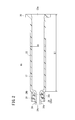
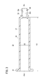
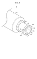
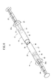
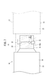
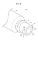
- FIG. 1 It is a perspective view of a syringe kit concerning an embodiment of the present invention. It is sectional drawing of the barrel for male syringes. It is sectional drawing of the barrel for female syringes. It is a perspective view of the tip part of the barrel for female syringes. It is a side view of the tip part of the barrel for female syringes. It is a perspective view of the state which connected the male syringe and the female syringe. It is a schematic diagram explaining that the permite
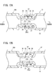
- FIG. 12A is a cross-sectional view of a state in which a barrel for a female syringe and a barrel for a male syringe according to a second modification are connected, and FIG.
- FIG. 12B is a cross-sectional view along the line XIIB-XIIB in FIG. 12A. It is a schematic diagram explaining that the procedures
- the syringe kit 10 is a mixing kit for mixing the filling in one barrel and the filling in the other barrel.
- the syringe kit 10 includes a male syringe 12 and a female syringe 14 which can be screwed together. Both the male syringe 12 and the female syringe 14 are configured as prefilled syringes in which contents such as drugs are pre-filled.
- the side connected to the female syringe 14 or the direction thereof is referred to as “tip” or “tip direction”
- the opposite side or the reverse direction is “base” or “ It is called “proximal direction”.
- the side connected to the male syringe 12 or the direction thereof is referred to as “tip” or “tip direction”
- the opposite side or the reverse direction is “base end” or “base direction”.
- the male syringe 12 includes a hollow barrel for male syringe 16, a gasket 18 slidably inserted in the male syringe barrel 16, a pusher 20 connected to the gasket 18, and a barrel for male syringe 16 And the gasket 18 and the medicine M filled in the barrel chamber 17.
- the “male syringe barrel 16” will be abbreviated as the “male barrel 16”.
- the male barrel 16 has a substantially cylindrical shape and a barrel body 22 (male barrel body) having a proximal end opening 22 a formed at the base end, and provided at the tip of the barrel body 22. It has a nozzle 24, a lock adapter 26 provided outside the nozzle 24, and a flange 29 which is formed to project radially outward from the proximal end of the barrel body 22.
- the barrel body 22, the nozzle 24, the lock adapter 26 and the flange 29 are integrally formed.
- the outer diameter D1 of the barrel body 22 is not particularly limited, but is preferably 6.7 mm or more.
- the axial length L1 of the barrel 22 is not particularly limited, but is preferably 35 mm or more, and more preferably 47 mm or more.
- the nozzle 24 is reduced in diameter from the center of the tip end of the barrel body 22 to the barrel body 22 and extends in the tip direction.
- the nozzle 24 has a passage 24 b penetrating in the axial direction and in communication with the inner cavity (barrel chamber 17) of the barrel body 22.
- the nozzle 24 is configured as a male luer having a circular cross-sectional outer shape and having a tapered outer peripheral surface 24 a whose outer diameter decreases in the direction of the tip.
- the nozzle 24 can be fitted to a later-described cylindrical portion 38 (female luer) of the female syringe 14.
- the nozzle 24 protrudes in the tip direction more than the tip surface of the lock adapter 26.
- a cap (not shown) is attached to the nozzle 24, and the tip opening 24c of the nozzle 24 is sealed by the cap.
- the cap is removed from the nozzle 24 when using the male syringe 12 (when using the syringe kit 10).
- the lock adapter 26 is formed in a substantially hollow cylindrical shape that extends from the tip end of the barrel body 22 toward the tip end and surrounds the nozzle 24 concentrically. Between the inner peripheral portion of the lock adapter 26 and the outer peripheral portion of the nozzle 24, an annular recess 26a opened in the tip direction is formed. A screw 28 is formed on the inner peripheral surface of the lock adapter 26. The screw 28 has a thread 28 a projecting inward from the inner peripheral surface of the lock adapter 26.
- the gasket 18 is inserted into the barrel body 22 via a proximal end opening 22 a that opens at the proximal end of the barrel body 22.
- the proximal end side of the barrel body 22 is sealed in a liquid tight manner by the gasket 18.
- the gasket 18 is made of, for example, an elastic material such as a rubber material.
- the gasket 18 has an outer peripheral portion in fluid tight contact with the inner peripheral surface of the barrel body 22 and is slidably disposed in the barrel body 22.
- a gasket 18 is connected to the tip of the pusher 20. As the user presses the pusher 20 in the axial direction (the distal direction or the proximal direction), the gasket 18 slides in the axial direction in the barrel body 22.
- the pusher 20 may be connected to the gasket 18 when using the male syringe 12.
- drugs M include, for example, protein preparations, peptide preparations, antitumor agents, vitamins (multivitamins), various amino acids, antithrombotic agents such as heparin, insulin, antibiotics, analgesics, cardiac agents, statics Injection anesthetics, medical narcotics, anti-parkinsonian agents, ulcer treatment agents, corticosteroids, arrhythmic agents and the like can be mentioned.
- the female syringe 14 comprises a hollow barrel 30 for a female syringe, a gasket 32 slidably inserted in the barrel 30 for a female syringe, a pusher 34 connected to the gasket 32, and a barrel 30 for a female syringe. And the gasket 32 to fill the barrel chamber 37 with the medical fluid ML.
- the “female syringe barrel 30” will be abbreviated as the “female barrel 30”.
- the female barrel 30 has a substantially cylindrical shape and a barrel body 36 (female barrel body) having a proximal end opening 36a formed at the proximal end, and from the tip of the barrel body 36 in the distal direction It has the cylinder part 38 which protruded, and the flange 40 protruded and formed radially outward from the base end of the barrel trunk
- the barrel body 36, the cylindrical portion 38 and the flange 40 are integrally formed.
- the cylindrical portion 38 is thinner than the barrel body 36 in FIG. 3, the cylindrical portion 38 may have the same thickness as the barrel body 36 or may be thicker than the barrel body 36.
- the outer diameter D2 of the barrel body 36 is not particularly limited, but is preferably 6.7 mm or more.
- the axial length L2 of the barrel portion 36 is not particularly limited, but is preferably 35 mm or more, and more preferably 47 mm or more.
- the cylindrical portion 38 is reduced in diameter from the center of the tip of the barrel body 36 to the barrel body 36 and extends in the distal direction.
- the cylindrical portion 38 has a passage 38 b penetrating in the axial direction and in communication with the inner cavity (barrel chamber 37) of the barrel body 36.
- the cylindrical portion 38 is configured as a female luer having a tapered inner circumferential surface 38 a whose outer diameter increases in the distal direction.
- each protrusion 42 protruding outward (radially outward) opposite to each other with respect to the axial line (center line) of the cylindrical portion 38 are provided ing.
- the two protrusions 42 have the same shape and size.
- the two projections 42 can be screwed with screws 28 (see FIG. 2) provided on the lock adapter 26 of the male barrel 16.
- Each protrusion 42 extends in an arc shape in the circumferential direction along the outer peripheral surface of the cylindrical portion 38.
- the length Lp of the protrusion 42 along the radial direction of the cylindrical portion 38 is set to 35 to 65% of the outer diameter Dc of the cylindrical portion 38. Specifically, the length Lp of the protrusion 42 is set to 2.0 to 4.5 mm.
- the length Lp of the projection 42 is perpendicular to the axis of the cylindrical portion 38, and the external dimension of the projecting end of the projection 42 in the direction along the direction perpendicular to the projection direction of the projection 42 from the cylindrical portion 38. (See also FIG. 4).
- the width W of the projection 42 along the axial direction of the cylindrical portion 38 is set to 1.0 to 1.5 mm.
- the base end of the projection 42 (the end of the projection 42 on the barrel body 36 side) is provided with an inclined surface 42a opposite to the trailing flank of the screw 28 (see FIG. 2) of the lock adapter 26 described above. . That is, the inclined surface 42 a is inclined with respect to the circumferential direction of the cylindrical portion 38 so as to be substantially parallel to the spiral extension direction of the screw 28 when the projection 42 is screwed with the screw 28.
- a ring-shaped protrusion 44 that protrudes outward from the tip end of the cylindrical portion 38 is integrally provided.
- the ring-shaped protrusion 44 extends in the circumferential direction along the outer peripheral surface of the cylinder 38 around the axis of the cylinder 38.
- the ring-shaped projection 44 is connected to the two projections 42.
- two protrusions 42 are integrally provided on the outer peripheral portion of the ring-shaped protrusion 44.
- the two protrusions 42 protrude outward from the outer peripheral portion of the ring-shaped protrusion 44.
- each protrusion 42 protrudes in the proximal direction (barrel barrel 36 side) more than the proximal end surface of the ring-like protrusion 44 (end surface of the ring-like protrusion 44 on the barrel body 36 side).
- a tip protruding portion 46 protruding in the tip direction from the tip end of the cylindrical portion 38 is integrally provided.
- the distal end protruding portion 46 extends in a ring shape in the circumferential direction concentrically with the cylindrical portion 38.
- the outer diameter of the distal end protruding portion 46 is smaller than the outer diameter Dc of the cylindrical portion 38.
- the outer diameter of the distal end protruding portion 46 may be the same as the outer diameter Dc of the cylindrical portion 38, or may be larger than the outer diameter Dc of the cylindrical portion 38.
- the gasket 32 is inserted into the barrel body 36 via a proximal end opening 36 a that opens at the proximal end of the barrel body 36.
- the gasket 32 seals the proximal end of the barrel body 36 in a fluid-tight manner.
- the gasket 32 is made of, for example, an elastic material such as a rubber material.
- the gasket 32 has its outer peripheral portion in fluid tight contact with the inner peripheral surface of the barrel body 36 and is slidably disposed in the barrel body 36.
- a gasket 32 is connected to the tip of the pusher 34.
- the gasket 32 slides in the axial direction in the barrel body 36.
- the pusher 34 may be connected to the gasket 32 when using the female syringe 14.
- a cap (not shown) is attached to the cylindrical portion 38, and the tip opening 38c (see FIG. 3) is sealed by the cap.
- the cap is removed from the cylindrical portion 38 when the female syringe 14 is used (when the syringe kit 10 is used).
- the medical fluid ML is a fluid in which the drug M in the male syringe 12 can be dissolved, diluted or mixed.
- Such medical fluid ML may be a drug solution such as physiological saline, a drug dilute solution, a drug mixture, or a drug solution containing a drug (eg, a vitamin drug, minerals).
- the medical fluid ML may not be previously filled in the female syringe 14 as in the present embodiment, and may be a required amount of suction from a vial or the like into the empty female syringe 14 as necessary.
- the male barrel 16 and the female barrel 30 are both made of cyclic polyolefin having high rigidity and high toughness.
- Male barrel 16 and female barrel 30 may be made of polypropylene, polyethylene, polystyrene, polyamide, polycarbonate, polyvinyl chloride, poly- (4-methylpentene-1), acrylic resin, acrylonitrile-butadiene-styrene copolymer, polyethylene terephthalate, etc. It may be made of polyester or the like.
- caps are removed (opened) from the nozzle 24 of the male barrel 16 and the cylindrical portion 38 of the female barrel 30, respectively.
- the male barrel 16 and the female barrel 30 are connected to each other.
- the screw 28 (see FIG. 2) of the lock adapter 26 and the projection 42 (see FIG. 3) provided on the cylindrical portion 38 of the female barrel 30 are screwed together.
- the nozzle 24 (male luer) of the male barrel 16 is inserted into the cylindrical portion 38 (female luer) of the female barrel 30.
- the tapered outer peripheral surface 24 a (see FIG. 2) of the nozzle 24 fits (taper-fits) in a fluid tight manner with the tapered inner peripheral surface 38 a (see FIG. 3) of the cylindrical portion 38.
- the medical fluid ML and the medicine M are mixed by performing a pumping operation using the pushers 20 of the male syringe 12 and the pushers 34 of the female syringe 14.
- the medical fluid ML is injected from the inside of the female barrel 30 into the male barrel 16 by pressing the pusher 34 of the female syringe 14 toward the distal end of the female syringe 14, and the medical fluid ML in the male barrel 16.
- drug M are mixed.
- the pusher 20 of the male syringe 12 is pressed in the direction of the tip of the male syringe 12 to inject the mixed solution (the mixture of the medical fluid ML and the drug M) into the female barrel 30 from inside the male barrel 16 Do.
- dissolution, dilution or mixing of the drug M is promoted, and a desired drug solution is prepared.
- the cylindrical portion 38 of the female barrel 30 is provided with two protrusions 42 that can be screwed into the screw 28 of the lock adapter 26 of the male barrel 16.
- the length Lp of the projection 42 in the direction perpendicular to the axis of the cylindrical portion 38 and in the direction perpendicular to the direction in which the projection 42 protrudes from the cylindrical portion 38 is 2.0 to 4.5 mm.
- the width W of the projection 42 along the axial direction of the frame is 1.0 to 2.1 mm.
- an inclined surface 42 a is provided to face the trailing flank of the screw 28 of the lock adapter 26.
- the projection 42 is a screw thread 28a of the lock adapter 26. (The projection 42 idles).
- the projections 42 shown by imaginary lines are the projections 42 before passing over the screw thread 28 a.
- the screwing between the projection 42 and the screw 28 progresses to a certain degree, the fitting between the tapered outer peripheral surface 24 a of the nozzle 24 and the tapered inner peripheral surface 38 a of the cylindrical portion 38 is completed. Then, when it is further attempted to screw in this state, mainly the elastic deformation of the screw 28 (lock adapter 26) outward causes the projection 42 to go over the screw thread 28a.
- the protrusion 42 passes over the screw thread 28 a does not mean that the protrusion 42 moves along the spiral shape of the screw 28, and the protrusion 42 straddles the top of the screw thread 28 a and one side of the screw thread 28 a To move from one side to the other side.
- a male reference connector is defined in ISO 594-2 as a test connector for a lock type connector by screw connection.
- the female syringe 14 is engaged when the convex reference conical fitting for stress crack test specified in ISO594-2 and the female syringe 14 are screwed.
- the projection 42 rides over the thread 28 a of the lock adapter 26 with a torque that is less than the torque at which the 14 breaks. Therefore, breakage of the cylindrical portion 38 of the female syringe 14 can be prevented more reliably.
- the convex reference conical fitting is made of a material having corrosion resistance (for example, stainless steel).
- a ring-shaped protrusion 44 (see FIG. 4) protruding outward from the tip end of the cylindrical portion 38 is provided, and the protrusion 42 is formed on the outer peripheral portion of the ring-shaped protrusion 44 There is.
- the projection 42 and the cylindrical portion 38 are reinforced. Therefore, when the projection 42 rides over the screw thread 28 a of the lock adapter 26, the projection 42 and the cylindrical portion 38 are not easily deformed, and the liquid tightness between the nozzle 24 and the cylindrical portion 38 is well maintained.
- a distal end projecting portion 46 (see FIG. 4) projecting from the distal end portion of the cylindrical portion 38 to the distal end side is provided, and the distal end projecting portion 46 is positioned distal to the projection 42.
- the projection 42 and the cylindrical portion 38 are reinforced. Therefore, when the projection 42 rides over the screw thread 28 a of the lock adapter 26, the projection 42 and the cylindrical portion 38 are not easily deformed, and the liquid tightness between the nozzle 24 and the cylindrical portion 38 is well maintained.
- the female barrel 30 is made of cyclic polyolefin having high rigidity and toughness
- the projection 42 and the cylindrical portion 38 are not easily deformed, and the nozzle 24 and the cylinder
- the liquid tightness with the portion 38 is well maintained.
- the male barrel 16 is also made of cyclic polyolefin having high rigidity and toughness, the nozzle 24 is not easily deformed when the protrusion 42 passes over the screw thread 28 a of the lock adapter 26. And the liquid tightness of the
- the outer diameter D1 of the barrel body 22 of the male barrel 16 and the outer diameter D2 of the barrel body 36 of the female barrel 30 are both 6.7 mm or more.
- the axial length L1 of the barrel body 22 of the male barrel 16 and the axial length L2 of the barrel body 36 of the female barrel 30 are each 35 mm or more.
- the barrel body is gripped and screwed, so that screwing is possible with certainty, but a strong torque is likely to be applied, resulting in cracking or deformation It's easy to do.
- the present invention even if the barrel body parts 22 and 36 have the above-mentioned external dimensions, the projection 42 passes over the screw thread 28a, thereby preventing damage and deformation of the cylindrical part 38 as described above As a result, it is possible to effectively prevent the liquid tightness between the nozzle 24 and the cylindrical portion 38 from being reduced. Therefore, the present invention is particularly useful when the barrel body 22, 36 has the above-mentioned external dimensions.
- the two projections 42 when screwing the screw 28 and the two projections 42, the two projections 42 move over the screw thread 28a of the lock adapter 26 by a predetermined torque, and the projections 42 (and the screws 28) Produces a feeling of click. For this reason, the user who performed the screwing operation can easily know that the screwing between the projection 42 and the screw 28 is completed based on the generated click feeling, and the next step (the mixing operation described above) You can move quickly to The projections 42 (and the screws 28) may generate a click sound as well as a click feeling.
- a barrel 30a for female syringe according to a first modification shown in FIGS. 8 and 9 (hereinafter, abbreviated as “female barrel 30a”) may be employed.
- This female barrel 30a is provided with a cylindrical portion 39 in place of the cylindrical portion 38 in the female barrel 30 shown in FIG.
- the cylindrical portion 39 is provided on the outer peripheral portion of the cylindrical portion 39 on two opposite sides with two screws 28 (see FIG. 10) screwable on the lock adapter 26 of the male syringe 12.
- the projection 43 is provided.
- the length Lpa of each protrusion 43 (the top of each protrusion 43) along the radial direction of the cylindrical portion 39 is set to 2.7 to 3.5 mm.
- the width Wa of each protrusion 43 (the top of each protrusion 43) along the axial direction of the cylindrical portion 39 is set to 1.5 to 2.1 mm.
- the length Lpa of each protrusion 43 may be set to 2.0 to 4.5 mm, similarly to the length Lp of each protrusion 42, and the width Wa of each protrusion 43 is the width of each protrusion 42.
- W it may be set to 1.0 to 2.1 mm.
- each of the two projections 43 of the female barrel 30 a has an inclined surface facing the trailing flank of the screw 28 of the lock adapter 26 when the two projections 43 are screwed with the screw 28 of the lock adapter 26.
- 43a is provided.
- the inclined surface 43a is configured in the same manner as the inclined surface 42a (see FIG. 5) provided on each protrusion 42 of the above-described female barrel 30.
- Each protrusion 43 has a chamfered corner 43b chamfered on the side opposite to the inclined surface 42a.
- the chamfered corner 43 b is an arc-shaped curved surface.
- the cylindrical portion 39 includes an abutting portion 45 having an outer diameter Dd of 6.4 to 6.8 mm at a position closer to the base end than the two projections 43 on the outer peripheral portion of the cylindrical portion 39.
- the contact portion 45 is an axis of the cylindrical portion 39 with respect to the axis of the lock adapter 26.
- the outer diameter Dd of the contact portion 45 is constant along the axial direction of the cylindrical portion 39.
- the contact portion 45 in the illustrated example is an annular surface (cylindrical surface) extending around the entire circumference of the axis of the cylindrical portion 39.
- the external shape of the contact portion 45 in a cross section perpendicular to the axis of the cylindrical portion 39 is not limited to a circular shape, and may be a non-circular shape such as a polygon.
- the contact portion 45 may be partially present in the circumferential direction on the outer circumferential portion, not on the entire circumference of the outer circumferential portion of the cylindrical portion 39.
- the contact portion 45 is continuously provided from the base end 43 c of the two projections 43 to a position at least 4 mm away from the tip 39 a of the cylindrical portion 39 toward the barrel body 36.
- the length Lt of the contact portion 45 along the axial direction of the cylindrical portion 39 is preferably larger than the width Wa of the protrusion 43.
- the female barrel 30a is provided with an abutting portion 45 having an outer diameter Dd of 6.4 to 6.8 mm at a position closer to the base end than the two projections 43 on the outer peripheral portion of the cylindrical portion 39. Therefore, as shown in FIG. 10, when the two projections 43 of the cylindrical portion 39 are screwed with the screw 28 of the lock adapter 26 of the male syringe 12, the contact portion 45 is the inner circumferential surface 27b of the screw 28 of the lock adapter 26. And the inclination of the axis of the cylindrical portion 39 with respect to the axis of the lock adapter 26 is suppressed. For this reason, the crack of the cylinder part 39 by making it screw together with an axis
- the length Lpa of the protrusion 43 is 2.7 to 3.5 mm
- the width Wa of the protrusion 43 is 1.5 to 2.1 mm
- the protrusion 43 is a side surface facing the inclined surface 43a.
- a female syringe barrel 30A according to a second modification shown in FIG. 11 (hereinafter, abbreviated as “female barrel 30A”) may be employed instead of the female barrel 30.
- the female barrel 30A is obtained by adding a proximal end side protrusion 50 to the female barrel 30 shown in FIG.
- the proximal end side projecting portion 50 projects from the outer peripheral portion of the cylindrical portion 38, and is provided at a position closer to the proximal side than the protrusion 42 at intervals in the axial direction of the cylindrical portion 38.
- the proximal end side projecting portion 50 protrudes outward in the opposite direction with respect to the proximal end side ring-shaped projecting portion 52 projecting outward from the outer peripheral portion of the cylindrical portion 38 and the axis of the cylindrical portion 38 And two proximal projections 54.
- the proximal end side ring shaped protrusion 52 has the same configuration as the ring shaped protrusion 44.
- the two proximal end projections 54 are provided on the outer peripheral portion of the proximal end ring-shaped projection 52 and have the same configuration as the two projections 42.
- the two proximal end protrusions 54 are provided at the same circumferential position as the two protrusions 42.
- the proximal end side projecting portion 50 protruding from the outer peripheral portion of the cylindrical portion 38 is provided at a position closer to the proximal end than the two projections 42. Accordingly, as shown in FIGS. 12A and 12B, when the two projections 42 of the cylindrical portion 38 are screwed with the screw 28 of the lock adapter 26 of the male syringe 12, the proximal end side protrusion 50 is the inner periphery of the lock adapter 26. By contacting the surface 27, the inclination of the axis of the cylindrical portion 38 with respect to the axis of the lock adapter 26 is suppressed. For this reason, the crack of the cylinder part 38 by making it screw together with an axis
- the stress applied to the cylindrical portion 38 may become uneven in the circumferential direction and the cylindrical portion 38 may be broken.
- the inclination of the axis of the cylindrical portion 38 with respect to the axis of the lock adapter 26 is suppressed by the proximal end side projecting portion 50 at the time of screwing. It is possible to prevent cracking of the cylindrical portion 38 due to non-uniformity in the circumferential direction.
- the proximal end side projection 54 is provided between the inner peripheral surface 27 a between the screw threads 28 a of the lock adapter 26 and the inner peripheral surface 27 b of the screw threads 28 a of the lock adapter 26. This is achieved by abutting on at least one side. That is, at the time of screwing, the base end side protrusion 54 faces the inner peripheral surface 27 a between the screw threads 28 a of the lock adapter 26 (FIG. 12A), and the base end side ring-shaped projection 52 is a screw of the lock adapter 26. It faces the inner circumferential surface 27b of the mountain 28a (FIG. 12B).
- the proximal end protrusion 54 abuts against the inner circumferential surface 27a between the screw threads 28a of the lock adapter 26 during screwing, and the proximal end ring
- the projection 52 is achieved by functioning as an abutting portion that abuts on the inner circumferential surface 27 b of the screw thread 28 a of the lock adapter 26.
- the inner circumferential surface 27 of the lock adapter 26 includes the inner circumferential surface 27a between the screw threads 28a and the inner circumferential surface 27b of the screw thread 28a.
- the base end side projection 54 abuts on the inner peripheral surface 27 a between the screw threads 28 a of the lock adapter 26, and the base end side ring-shaped projection 52 is of the screw thread 28 a of the lock adapter 26. It may not be in contact with the inner circumferential surface 27b.
- the proximal end ring-shaped projection 52 abuts on the inner circumferential surface 27 b of the thread 28 a of the lock adapter 26, and the proximal end projection 54 is between the threads 28 a of the lock adapter 26. It may not be in contact with the inner circumferential surface 27a.
- the base end side projection 54 is omitted, and the base end side ring-shaped projection 52 functions as an abutting portion to be in contact with the inner peripheral surface 27 b of the screw thread 28 a of the lock adapter 26 during screwing. May be In this case, the outer diameter of the proximal ring-shaped projection 52 is preferably 6.4 to 6.8 mm.
- a female syringe barrel 30B according to a third modification shown in FIG. 14 (hereinafter, abbreviated as “female barrel 30B”) may be employed instead of the female barrel 30.
- the female barrel 30B includes a female barrel main body 60, an outer peripheral portion of the cylindrical portion 38 of the female barrel main body 60, and an outer cylinder 62 which can not rotate with respect to the cylindrical portion 38. Since the female barrel main body 60 has the same configuration as the above-described female barrel 30, the constituent elements thereof are given the same reference numerals as the constituent elements of the female barrel 30.
- the outer cylinder 62 shown in FIG. 14 is configured to be removable from the female barrel main body 60.
- the outer cylinder 62 includes a body 64 covering the barrel body 36 of the female barrel body 60, a tip tube 66 extending distally from the tip of the body 64, and a base end of the body 64 from each other. And a pair of opposite outwardly projecting engagement portions 68.
- the outer cylinder 62 is made of a transparent material (for example, the same material as that of the female barrel main body 60) so that the female barrel main body 60 (and its inside) disposed inside can be viewed.
- the distal end cylindrical portion 66 is a hollow cylindrical body surrounding the cylindrical portion 38 of the female barrel main body 60, and is disposed concentrically with the cylindrical portion 38. An annular space is formed between the distal end cylindrical portion 66 and the cylindrical portion 38.
- the distal end cylindrical portion 66 is formed to cover the protrusion 42 provided on the cylindrical portion 38. Specifically, as shown in FIG. 15, in the state where the outer cylinder 62 is attached to the female barrel main body 60, the front end surface 66a of the front end cylindrical portion 66 is closer to the front end surface 42b of the projection 42 provided on the cylindrical portion 38. Is also located on the tip side. The distal end surface 66a of the distal end cylindrical portion 66 may be located at an axial position between the distal end surface 42b of the projection 42 and the proximal end surface 42c. The inner diameter of the end barrel 66 is slightly larger than the outer diameter of the lock adapter 26 of the male barrel 16.
- the pair of engaging portions 68 engage with the edges on both sides in the short axis direction of the flange 40 of the female barrel main body 60. Thereby, the outer cylinder 62 can not rotate with respect to the female barrel main body 60.
- a hook that engages with the proximal end surface of the flange 40 may be provided on the engaging portion 68.
- the outer cylinder 62 is provided so as to surround the outer periphery of the cylindrical portion 38 and can not rotate with respect to the cylindrical portion 38. Therefore, as shown in FIG. 15, when the two projections 42 of the cylindrical portion 38 are screwed with the screw 28 of the lock adapter 26 of the male syringe 12, the lock adapter 26 is inserted between the cylindrical portion 38 and the outer cylinder 62. Be done. At this time, the inner peripheral surface of the outer cylinder 62 abuts on the outer peripheral surface of the lock adapter 26, whereby the inclination of the shaft of the cylindrical portion 38 with respect to the shaft of the lock adapter 26 is suppressed. For this reason, the crack of the cylinder part 38 by making it screw together with an axis
- the outer cylinder 62 is not limited to the shape surrounding most of the female barrel main body 60 as described above, and may be integrally formed with the female barrel main body 60 only around the cylindrical portion 38.
- the male syringe 12 is filled with the drug M and the female syringe 14 is filled with the medical fluid ML is illustrated, but the filling is reversed between the male syringe 12 and the female syringe 14 It is also good. That is, the male syringe 12 may be filled with the medical fluid ML, and the female syringe 14 may be filled with the drug M.
Landscapes
- Health & Medical Sciences (AREA)
- Life Sciences & Earth Sciences (AREA)
- Veterinary Medicine (AREA)
- Public Health (AREA)
- General Health & Medical Sciences (AREA)
- Animal Behavior & Ethology (AREA)
- Heart & Thoracic Surgery (AREA)
- Biomedical Technology (AREA)
- Hematology (AREA)
- Anesthesiology (AREA)
- Engineering & Computer Science (AREA)
- Vascular Medicine (AREA)
- Pharmacology & Pharmacy (AREA)
- Physics & Mathematics (AREA)
- Fluid Mechanics (AREA)
- Diabetes (AREA)
- Pulmonology (AREA)
- Infusion, Injection, And Reservoir Apparatuses (AREA)
Abstract
Description
Claims (15)
- ガスケット(32)が摺動可能な内周面を有する中空のバレル胴部(36)と、
前記バレル胴部(36)の先端から先端方向に突出し、オスシリンジ(12)のノズル(24)が嵌合可能なメスルアーとして構成された筒部(38、39)と、を備えたメスシリンジ用バレル(30、30a、30A、30B)であって、
前記筒部(38、39)は、前記筒部(38、39)の外周部において互いに反対側に設けられ、前記オスシリンジ(12)のロックアダプタ(26)に設けられたネジ(28)と螺合可能な2つの突起(42、43)を有し、
前記筒部(38、39)の軸と垂直、かつ、前記突起(42、43)の前記筒部(38、39)からの突出方向と垂直な方向に沿った前記突起(42、43)の長さ(Lp)は、2.0~4.5mmであり、
前記筒部(38、39)の軸方向に沿った前記突起(42、43)の幅(W、Wa)は、1.0~2.1mmであり、
前記2つの突起(42、43)の各々は、前記2つの突起(42、43)が前記ロックアダプタ(26)の前記ネジ(28)と螺合する際に前記ロックアダプタ(26)の前記ネジ(28)の追い側フランクに対向する傾斜面(42a、43a)を前記バレル胴部(36)側の端部に有する、
ことを特徴とするメスシリンジ用バレル(30、30a、30A、30B)。 - 請求項1記載のメスシリンジ用バレル(30、30A、30B)において、
前記筒部(38)は、前記筒部(38)の先端部から外方に突出したリング状突部(44)を有し、
前記2つの突起(42)は、前記リング状突部(44)の外周部上に形成されている、
ことを特徴とするメスシリンジ用バレル(30、30A、30B)。 - 請求項1又は2記載のメスシリンジ用バレル(30、30A、30B)において、
前記筒部(38)の先端部から先端側に突出した先端突出部(46)が設けられており、
前記先端突出部(46)は、前記2つの突起(42)よりも先端側に位置している、
ことを特徴とするメスシリンジ用バレル(30、30A、30B)。 - 請求項1~3のいずれか1項に記載のメスシリンジ用バレル(30、30a、30A、30B)において、
前記メスシリンジ用バレル(30、30a、30A、30B)は、環状ポリオレフィンからなる、
ことを特徴とするメスシリンジ用バレル(30、30a、30A、30B)。 - 請求項1~4のいずれか1項に記載のメスシリンジ用バレル(30、30a、30A、30B)において、
前記バレル胴部(36)の外径(D2)が6.7mm以上であり、
前記バレル胴部(36)の軸方向長さ(L2)が35mm以上である、
ことを特徴とするメスシリンジ用バレル(30、30a、30A、30B)。 - 請求項1~5のいずれか1項に記載のメスシリンジ用バレル(30A)において、
前記筒部(38)は、前記筒部(38)の前記外周部から突出し、前記突起(42)よりも基端側の位置に設けられた基端側突出部(50)を有し、
前記筒部(38)の前記2つの突起(42)が前記オスシリンジ(12)の前記ロックアダプタ(26)の前記ネジ(28)と螺合する際に、前記基端側突出部(50)は、前記ロックアダプタ(26)の軸に対する前記筒部(38)の軸の傾きを抑制するように、前記ロックアダプタ(26)の内周面と当接する
ことを特徴とするメスシリンジ用バレル(30A)。 - 請求項1~5のいずれか1項に記載のメスシリンジ用バレル(30a、30A)において、
前記筒部(38、39)は、前記筒部(38、39)の前記外周部に、6.4~6.8mmの外径を有する当接部(45、52)を備え、
前記当接部(45、52)は、前記2つの突起(42、43)よりも基端側に位置し、
前記筒部(38、39)の前記2つの突起(42、43)が前記オスシリンジ(12)の前記ロックアダプタ(26)の前記ネジ(28)と螺合する際に、前記当接部(45、52)は、前記ロックアダプタ(26)の軸に対する前記筒部(38、39)の軸の傾きを抑制するように、前記ロックアダプタ(26)の前記ネジ(28)の内周面(27b)と当接する、
ことを特徴とするメスシリンジ用バレル(30a、30A)。 - 請求項7記載のメスシリンジ用バレル(30a)において、
前記当接部(45)は、前記2つの突起(43)の基端(43c)から、前記筒部(39)の先端(39a)から前記メスバレル胴部(36)に向かって少なくとも4mm離間した位置まで連続的に設けられている、
ことを特徴とするメスシリンジ用バレル(30a)。 - 請求項1~8のいずれか1項に記載のメスシリンジ用バレル(30B)において、
前記筒部(38)の前記外周部を取り囲み、前記筒部(38)に対して回転不能な外筒(62)をさらに備え、
前記筒部(38)の前記2つの突起(42)が前記オスシリンジ(12)の前記ロックアダプタ(26)の前記ネジ(28)と螺合する際に、前記ロックアダプタ(26)が前記筒部(38)と前記外筒(62)との間に挿入され、前記外筒(62)の内周面が前記ロックアダプタ(26)の外周面と当接することにより、前記ロックアダプタ(26)の軸に対する前記筒部(38)の軸の傾きが抑制される、
ことを特徴とするメスシリンジ用バレル(30B)。 - オスルアーとして構成されたノズル(24)と、前記ノズル(24)の外周面を取り囲み、内周面にネジ(28)が設けられたロックアダプタ(26)と、前記ノズル(24)及び前記ロックアダプタ(26)と連結されたオスバレル胴部(22)と、を含むオスシリンジ用バレル(16)を有するオスシリンジ(12)と、
前記ノズル(24)が嵌合可能なメスルアーとして構成された筒部(38、39)と、前記筒部(38、39)の外周面から突出し、前記ロックアダプタ(26)の前記ネジ(28)と螺合可能な2つの突起(42、43)と、前記筒部(38、39)と連結されたメスバレル胴部(36)と、を含むメスシリンジ用バレル(30、30a、30A、30B)を有するメスシリンジ(14)と、を備え、
前記ネジ(28)と前記2つの突起(42、43)とを螺合させる際に、ISO594-2に規定された応力亀裂試験用の凸形基準円錐フィッティングと前記メスシリンジ(14)とを螺合させた場合に前記メスシリンジ(14)が破損するトルクよりも小さいトルクによって、前記突起(42、43)が前記ロックアダプタ(26)のネジ山(28a)を乗り越える、
ことを特徴とするシリンジキット(10)。 - 請求項10記載のシリンジキット(10)において、
前記オスシリンジ用バレル(16)及び前記メスシリンジ用バレル(30、30a、30A、30B)はともに、環状ポリオレフィンからなる、
ことを特徴とするシリンジキット(10)。 - 請求項10又は11記載のシリンジキット(10)において、
前記オスバレル胴部(22)の外径(D1)及び前記メスバレル胴部(36)の外径(D2)は、ともに6.7mm以上であり、
前記オスバレル胴部(22)の軸方向長さ(L1)及び前記メスバレル胴部(36)の軸方向長さ(L2)は、ともに35mm以上である、
ことを特徴とするシリンジキット(10)。 - 請求項10~12のいずれか1項に記載のシリンジキット(10)において、
前記ロックアダプタ(26)の前記ネジ(28)の内径は6.8~7.2mmであり、
前記筒部(38、39)は、前記筒部(38、39)の前記外周部に、前記2つの突起(42、43)よりも基端側の位置に設けられた当接部(45、52)を有し、
前記当接部(45、52)は、6.4~6.8mmの外径を有し、
前記筒部(38、39)の前記2つの突起(42、43)が前記オスシリンジ(12)の前記ロックアダプタ(26)の前記ネジ(28)と螺合する際に、前記当接部(45、52)は、前記ロックアダプタ(26)の軸に対する前記筒部(38、39)の軸の傾きを抑制するように、前記ロックアダプタ(26)の前記ネジ(28)の内周面と当接する、
ことを特徴とするシリンジキット(10)。 - オスシリンジ(12)とメスシリンジ(14)とを螺合により接続するシリンジ接続方法であって、
前記オスシリンジ(12)は、オスルアーとして構成されたノズル(24)と、ネジ(28)が設けられたロックアダプタ(26)とを含むオスシリンジ用バレル(16)を有し、
前記メスシリンジ(14)は、前記ノズル(24)が嵌合可能なメスルアーとして構成された筒部(38、39)と、前記ロックアダプタ(26)の前記ネジ(28)と螺合可能な2つの突起(42、43)とを含むメスシリンジ用バレル(30、30a、30A、30B)を有し、
前記ネジ(28)と前記2つの突起(42、43)とを螺合させる際に、所定トルクにより前記突起(42、43)が前記ロックアダプタ(26)のネジ山(28a)を乗り越え、この乗り越えに伴ってクリック感を発生させる、
ことを特徴とするシリンジ接続方法。 - 請求項14記載のシリンジ接続方法において、
前記筒部(38、39)は、前記筒部(38、39)の前記外周部に、前記2つの突起(42、43)よりも基端側の位置に設けられた当接部(45、52)を有し、
前記ネジ(28)と前記2つの突起(42、43)とを螺合させる際に、前記当接部(45、52)が前記ロックアダプタ(26)の内周面と当接することにより、前記ロックアダプタ(26)の軸に対する前記筒部(38、39)の軸の傾きが抑制される、
ことを特徴とするシリンジ接続方法。
Priority Applications (5)
| Application Number | Priority Date | Filing Date | Title |
|---|---|---|---|
| EP17928323.9A EP3679914B1 (en) | 2017-10-13 | 2017-10-13 | Barrel for female syringe, syringe kit and syringe connection method |
| CN201780095737.8A CN111194203B (zh) | 2017-10-13 | 2017-10-13 | 母注射器用筒体、注射器套件及注射器连接方法 |
| KR1020207009920A KR102522345B1 (ko) | 2017-10-13 | 2017-10-13 | 암형 시린지용 배럴, 시린지 키트 및 시린지 접속 방법 |
| PCT/JP2017/037181 WO2019073593A1 (ja) | 2017-10-13 | 2017-10-13 | メスシリンジ用バレル、シリンジキット及びシリンジ接続方法 |
| US16/846,801 US11998722B2 (en) | 2017-10-13 | 2020-04-13 | Female syringe barrel, syringe kit, and syringe connection method |
Applications Claiming Priority (1)
| Application Number | Priority Date | Filing Date | Title |
|---|---|---|---|
| PCT/JP2017/037181 WO2019073593A1 (ja) | 2017-10-13 | 2017-10-13 | メスシリンジ用バレル、シリンジキット及びシリンジ接続方法 |
Related Child Applications (1)
| Application Number | Title | Priority Date | Filing Date |
|---|---|---|---|
| US16/846,801 Continuation US11998722B2 (en) | 2017-10-13 | 2020-04-13 | Female syringe barrel, syringe kit, and syringe connection method |
Publications (1)
| Publication Number | Publication Date |
|---|---|
| WO2019073593A1 true WO2019073593A1 (ja) | 2019-04-18 |
Family
ID=66100470
Family Applications (1)
| Application Number | Title | Priority Date | Filing Date |
|---|---|---|---|
| PCT/JP2017/037181 Ceased WO2019073593A1 (ja) | 2017-10-13 | 2017-10-13 | メスシリンジ用バレル、シリンジキット及びシリンジ接続方法 |
Country Status (5)
| Country | Link |
|---|---|
| US (1) | US11998722B2 (ja) |
| EP (1) | EP3679914B1 (ja) |
| KR (1) | KR102522345B1 (ja) |
| CN (1) | CN111194203B (ja) |
| WO (1) | WO2019073593A1 (ja) |
Families Citing this family (2)
| Publication number | Priority date | Publication date | Assignee | Title |
|---|---|---|---|---|
| EP3974010A1 (de) * | 2020-09-23 | 2022-03-30 | Hubertus Goller Gesellschaft m.b.H. | Multifunktionsspritze |
| KR102925728B1 (ko) * | 2024-02-06 | 2026-02-11 | (주)다림티센 | 시린지 키트 |
Citations (3)
| Publication number | Priority date | Publication date | Assignee | Title |
|---|---|---|---|---|
| US20080140055A1 (en) * | 2006-12-08 | 2008-06-12 | Utah Medical Products, Inc. | Lockable enteral feeding adapter |
| JP2013520287A (ja) * | 2010-02-24 | 2013-06-06 | ベクトン・ディキンソン・アンド・カンパニー | 安全機構付き薬物送達コネクタ |
| JP2013132349A (ja) | 2011-12-26 | 2013-07-08 | Daikyo Seiko Ltd | 二薬混合用シリンジキット |
Family Cites Families (13)
| Publication number | Priority date | Publication date | Assignee | Title |
|---|---|---|---|---|
| US5533708A (en) * | 1992-06-04 | 1996-07-09 | Vernay Laboratories, Inc. | Medical coupling site valve body |
| US8226598B2 (en) * | 1999-09-24 | 2012-07-24 | Tolmar Therapeutics, Inc. | Coupling syringe system and methods for obtaining a mixed composition |
| US6610034B1 (en) * | 2000-01-21 | 2003-08-26 | Ultradent Products, Inc. | Thread locking structure |
| US20070068594A1 (en) * | 2005-09-26 | 2007-03-29 | Fischer Dan E | Syringe locking structures |
| JP4895767B2 (ja) * | 2006-11-15 | 2012-03-14 | 株式会社アルテ | 注射器のルアーロック型筒先 |
| US20080140020A1 (en) * | 2006-12-08 | 2008-06-12 | Utah Medical Products Inc. | Lockable enteral feeding adapter |
| WO2009084646A1 (ja) * | 2007-12-28 | 2009-07-09 | Terumo Kabushiki Kaisha | シリンジ用ガスケットおよびそれを備えたシリンジ |
| WO2012002315A1 (ja) * | 2010-06-30 | 2012-01-05 | テルモ株式会社 | コネクタおよびコネクタ組立体 |
| JP6491096B2 (ja) * | 2013-09-06 | 2019-03-27 | テルモ株式会社 | シリンジ用外筒及びプレフィルドシリンジ |
| EP3050591B1 (en) * | 2013-09-27 | 2018-09-19 | Terumo Kabushiki Kaisha | Syringe outer cylinder with puncture function, syringe with puncture function, and prefilled syringe with puncture function |
| KR102315224B1 (ko) * | 2013-12-11 | 2021-10-20 | 가부시끼가이샤 제이엠에스 | 수형 커넥터 |
| WO2015151692A1 (ja) * | 2014-03-31 | 2015-10-08 | テルモ株式会社 | シリンジ |
| EP3322473B1 (en) * | 2015-07-15 | 2026-03-25 | Avent, Inc. | Enteral adaptor couplings |
-
2017
- 2017-10-13 CN CN201780095737.8A patent/CN111194203B/zh active Active
- 2017-10-13 KR KR1020207009920A patent/KR102522345B1/ko active Active
- 2017-10-13 WO PCT/JP2017/037181 patent/WO2019073593A1/ja not_active Ceased
- 2017-10-13 EP EP17928323.9A patent/EP3679914B1/en active Active
-
2020
- 2020-04-13 US US16/846,801 patent/US11998722B2/en active Active
Patent Citations (3)
| Publication number | Priority date | Publication date | Assignee | Title |
|---|---|---|---|---|
| US20080140055A1 (en) * | 2006-12-08 | 2008-06-12 | Utah Medical Products, Inc. | Lockable enteral feeding adapter |
| JP2013520287A (ja) * | 2010-02-24 | 2013-06-06 | ベクトン・ディキンソン・アンド・カンパニー | 安全機構付き薬物送達コネクタ |
| JP2013132349A (ja) | 2011-12-26 | 2013-07-08 | Daikyo Seiko Ltd | 二薬混合用シリンジキット |
Non-Patent Citations (1)
| Title |
|---|
| See also references of EP3679914A4 |
Also Published As
| Publication number | Publication date |
|---|---|
| EP3679914A4 (en) | 2020-10-14 |
| KR20200071728A (ko) | 2020-06-19 |
| KR102522345B1 (ko) | 2023-04-18 |
| US20200238013A1 (en) | 2020-07-30 |
| EP3679914B1 (en) | 2022-05-11 |
| CN111194203B (zh) | 2023-04-28 |
| US11998722B2 (en) | 2024-06-04 |
| EP3679914A1 (en) | 2020-07-15 |
| CN111194203A (zh) | 2020-05-22 |
Similar Documents
| Publication | Publication Date | Title |
|---|---|---|
| US5688252A (en) | Syringe | |
| US8172814B2 (en) | Syringe plunger and syringe incorporating the plunger | |
| KR102591387B1 (ko) | 주입 시스템을 폐쇄하기 위한 팁 캡 조립체 | |
| CN101743029B (zh) | 具有减小无效空间的能拆卸针头注射器 | |
| US10155088B2 (en) | Prefilled disposable injection device | |
| US12121702B2 (en) | Dual chamber syringe and methods of use thereof | |
| WO2012105640A1 (ja) | 容器兼用注射器 | |
| US9616176B2 (en) | Syringe carpule for storing, transporting and in situ mixing of local anesthetic and buffer, and for delivery of buffered anesthetic solution and a piercing-mixing unit therefore | |
| US20220354747A1 (en) | Syringe set, syringe, and set | |
| US9757526B2 (en) | Drug administration instrument | |
| US11998722B2 (en) | Female syringe barrel, syringe kit, and syringe connection method | |
| JP6782581B2 (ja) | シリンジキット | |
| US11311680B2 (en) | Female syringe and syringe kit | |
| JP2002177395A (ja) | プレフィルドシリンジ用注射器およびプレフィルドシリンジ | |
| KR200486337Y1 (ko) | 호환성을 향상시킨 일회용 주사기 세트 | |
| US20200046609A1 (en) | Mixing vial | |
| JP6282441B2 (ja) | ノズル交換式薬剤注入器 | |
| JP2004016772A (ja) | プレフィルドシリンジ用注射器およびプレフィルドシリンジ | |
| JPH07136264A (ja) | 2成分混合予充填注射器 | |
| WO2020194565A1 (ja) | メスシリンジ用バレル及びメスシリンジ組立体 | |
| JPH0810325A (ja) | 注射器兼容器 | |
| WO2020194574A1 (ja) | メスシリンジ用バレル、メスシリンジ組立体及びシリンジキット | |
| JP2008099728A (ja) | 容器兼用注射器 | |
| KR20260037525A (ko) | 재사용 방지 구조를 갖는 시린지 | |
| KR101671891B1 (ko) | 일체형 주사 키트 |
Legal Events
| Date | Code | Title | Description |
|---|---|---|---|
| 121 | Ep: the epo has been informed by wipo that ep was designated in this application |
Ref document number: 17928323 Country of ref document: EP Kind code of ref document: A1 |
|
| ENP | Entry into the national phase |
Ref document number: 20207009920 Country of ref document: KR Kind code of ref document: A |
|
| NENP | Non-entry into the national phase |
Ref country code: DE |
|
| ENP | Entry into the national phase |
Ref document number: 2017928323 Country of ref document: EP Effective date: 20200409 |
|
| NENP | Non-entry into the national phase |
Ref country code: JP |