WO2019073624A1 - Chambre à air et matelas pneumatique - Google Patents
Chambre à air et matelas pneumatique Download PDFInfo
- Publication number
- WO2019073624A1 WO2019073624A1 PCT/JP2018/014022 JP2018014022W WO2019073624A1 WO 2019073624 A1 WO2019073624 A1 WO 2019073624A1 JP 2018014022 W JP2018014022 W JP 2018014022W WO 2019073624 A1 WO2019073624 A1 WO 2019073624A1
- Authority
- WO
- WIPO (PCT)
- Prior art keywords
- air
- cell
- cells
- mattress
- main
- Prior art date
- Legal status (The legal status is an assumption and is not a legal conclusion. Google has not performed a legal analysis and makes no representation as to the accuracy of the status listed.)
- Ceased
Links
Images







Classifications
-
- A—HUMAN NECESSITIES
- A47—FURNITURE; DOMESTIC ARTICLES OR APPLIANCES; COFFEE MILLS; SPICE MILLS; SUCTION CLEANERS IN GENERAL
- A47C—CHAIRS; SOFAS; BEDS
- A47C27/00—Spring, stuffed or fluid mattresses or cushions specially adapted for chairs, beds or sofas
- A47C27/08—Fluid mattresses
- A47C27/10—Fluid mattresses with two or more independently-fillable chambers
-
- A—HUMAN NECESSITIES
- A61—MEDICAL OR VETERINARY SCIENCE; HYGIENE
- A61G—TRANSPORT, PERSONAL CONVEYANCES, OR ACCOMMODATION SPECIALLY ADAPTED FOR PATIENTS OR DISABLED PERSONS; OPERATING TABLES OR CHAIRS; CHAIRS FOR DENTISTRY; FUNERAL DEVICES
- A61G7/00—Beds specially adapted for nursing; Devices for lifting patients or disabled persons
- A61G7/05—Parts, details or accessories of beds
- A61G7/057—Arrangements for preventing bed-sores or for supporting patients with burns, e.g. mattresses specially adapted therefor
Definitions
- the present invention relates to an air cell and an air mattress used for an air mattress for preventing bedsores.
- Bed sores are local skin pressure ulcers, which are often caused by ischemia resulting from continued compression of local skin tissue, such as bone protruding sites that receive weight.
- Air mattresses include a type that is used by being superimposed on a normal mattress (also called an overlay type) and a type that is used by replacing the normal mattress (also called a replacement type).
- the pressure of contact with the body is usually reduced by maintaining the air pressure in each air cell at a low pressure to the extent that the user's body sinks, thereby preventing bedsores.
- Patent Document 1 discloses a technology in which air cells are waved by dividing air cells arranged in parallel into a plurality of systems and inflating and contracting the air cells in order for each system.
- an air mattress that changes the pressure in the air cell sequentially is called a pressure switching type
- an air mattress that does not change the pressure in the air cell during use is called a stationary type.
- the pressure-switching-type air mattress is not a medical device but a welfare tool called a "bed slip prevention tool" to which a care insurance is applied.
- Patent Document 2 discloses a pressure switching type air mattress in which the internal pressure of the air cell is changed according to the inclination angle of the bed when raising the bed from the back (raising the part of the bed on which the upper body of the user rides). Is disclosed.
- the weight may be concentrated locally on the bone projection or the like.
- the upper body weight concentrates on the buttocks of the user.
- the deeply sunk part may reach the bottom of the air mattress.
- This condition of the body reaching the bottom of the air mattress is called bottomed.
- the anti-slip function is lost, which is preferable from the viewpoint of the user's safety. Absent.
- the present invention has been made in view of the above, and it is possible to prevent the bottoming without making the thickness of the air mattress thicker than in the prior art, and not relying on the sensor or the electrical automatic control function. It is an object to provide an air cell and mattress for preventing.
- an air cell which is one mode of the present invention is an air cell which constitutes an air mattress used by enclosing air in the inside, and is formed by a sheet material which consists of flexible resin material. Is formed of a first cell that expands in a tubular shape by enclosing air in the inside, and a sheet material made of a flexible resin material, and each inflates in a tubular shape by enclosing air in the inside Second and third cells attached to a region on the floor side of the air mattress in the outer peripheral surface of the first cell so as to be parallel to the longitudinal direction of the first cell Second and third cells, and the flow of air is interrupted between the first cell and the second and third cells, and the first, second, and third cells are When air is sealed in the cell, The serial second and third cells in which the first cell is supported.
- the diameter of the first cell is larger than the diameters of the second and third cells in a state where air is enclosed in the inside, and the diameters of the second and third cells are They may be equal to each other in a state in which the air is enclosed. In the air cell, air may be allowed to flow between the second cell and the third cell.
- the air cell may further include a film-like member mounted on the inner peripheral surface of the first cell in a direction substantially parallel to the floor surface of the air mattress.
- the air cell may further include a film-like member substantially orthogonal to the floor surface of the air mattress and straddled in a bellows shape on the inner peripheral surface of the first cell.
- the air cells are formed of a sheet material made of a flexible resin material, and are fourth and fifth cells which each expand in a cylindrical shape by enclosing air in the inside, and the first cell The fourth cell and the fifth cell attached parallel to the longitudinal direction of the first cell in the region opposite to the second cell and the third cell in the outer peripheral surface of good.
- the sheet members facing each other at the central portion in the short direction of the first cell are welded to one another along the longitudinal direction, and the welded region makes the inside of the first cell longer It may be separated into two regions extending in a direction parallel to the direction.
- the air mattress which is another aspect of this invention is a thing in which the several air cell containing at least the said air cell was arranged in parallel.
- Air adjusting means for periodically changing the internal pressure of only the air cells juxtaposed in the area except at least the area at both ends in the longitudinal direction among the plurality of air cells juxtaposed in the air mattress in the above air mattress May be provided.
- the flow of air may be blocked between the provided air cells.
- the air mattress performs an air pump for injecting air into at least one of the plurality of air cells, and performs supply of air injected from the air pump to the air cell and exhaust of the air at a predetermined cycle.
- a rotary valve for switching the internal pressure of the at least one of the air cells, and a solenoid valve provided in a flow path for discharging the air flowing into the rotary valve from the at least one of the air cells to the outside It may further comprise a solenoid valve set to open the valve and close the valve when the power is cut off.
- the air mattress is a second solenoid valve provided in a flow passage for introducing air from the air pump to the rotary valve, and the valve is opened during energization and is closed when the energization is shut off. It may further comprise a set second solenoid valve.
- the second and third cells are attached along the longitudinal direction of the first cell in the region on the floor side of the air mattress in the outer peripheral surface of the first cell, and Block the flow of air between the second and third cells and support the first cell by the second and third cells, so that the weight of the user is locally concentrated, Even in the case where a portion of the air sinks into the first cell having a low internal pressure, bottoming of the air mattress can be prevented. Further, since the pressure applied to the first cell is dispersed in the directions of the second and third cells, it is possible to reduce the reaction force (contact pressure) that each part of the user receives from the air cell.
- the bottoming can be prevented only by the structure of the air mattress, without thickening the thickness of the air mattress more than before and without relying on the sensor and the automatic control function. Therefore, it is possible to realize an air mattress that can be used safely by the user while securing the safety regarding the height of the air mattress.
- FIG. 2 is a cross-sectional view taken along line AA of FIG.
- FIG. 2 is a cross-sectional view taken along line AA of FIG.
- FIG. 2 is a schematic diagram for demonstrating the principle of the body pressure dispersion in the air cell shown in FIG.
- FIG. 2 is a flowchart which shows the manufacturing method of the air cell which concerns on the 1st Embodiment of this invention.
- FIG. 12 is a cross-sectional view taken along the line BB in FIG. It is sectional drawing which shows the air cell which concerns on the 4th Embodiment of this invention. It is an example of the top view of the air cell shown in FIG. It is sectional drawing which shows the air cell which concerns on the 5th Embodiment of this invention.
- FIG. 17 is a side view of the air mattress shown in FIG. It is a schematic diagram for demonstrating the basic principle of the air adjustment system which concerns on the 7th Embodiment of this invention.
- FIG. 1 is a perspective view showing an air cell according to a first embodiment of the present invention.
- FIG. 2 is a bottom view of the air cell shown in FIG.
- FIG. 3 is a cross-sectional view taken along line AA of FIG. Among these, (a) of FIG. 1 shows a state where no load is applied to the air cell, and (b) of FIG. 1 shows a state where a load is applied to the air cell.
- the air cell 10 according to the present embodiment is a component that constitutes an air mattress used by enclosing air inside. As will be described later, an air mattress is configured by arranging a plurality of air cells 10 as shown in FIG. 1 on a bed frame.
- the air cell 10 is formed of a sheet material made of a flexible resin material such as urethane, and includes three cells (main cell 110 and base cells 121 and 122) which expand in a cylindrical shape by enclosing air therein. Have. 1 to 3 show a state in which air is enclosed inside.
- the diameter of the main cell 110 is larger than the diameter of the base cells 121 and 122, preferably about 2 to 3 times.
- the two base cells 121 and 122 are attached to a region on the floor side of the air mattress in the outer peripheral surface of the main cell 110 so as to be substantially parallel to the longitudinal direction of the main cell 110.
- the size of the air cell 10 is not particularly limited as long as it can be adapted to a bed frame using an air mattress.
- a bed frame having a lateral length of 850 mm or 950 mm is generally used, so that the longitudinal length L1 of the air cell 10 is set to 830 mm so as to conform thereto. It is good to make it to a degree or about 930 mm.
- the width W1 of the air cell 10 in the short direction may be, for example, about 60 mm
- the thickness H1 (the height from the lower end of the base cells 121 and 122 to the upper end of the main cell 110) may be, for example, about 75 mm.
- the thickness H1 of the air cell 10 is determined such that a distance of 220 mm or more from the upper surface of the air mattress to the upper end of the side rail or the bed grip is secured.
- fixing portions 111 may be provided to fix the air cell 10 to the bed frame or to connect the air cells 10 to each other.
- the resin material forming the main cell 110 and the resin material forming the base cells 121 and 122 may be the same material or different materials.
- the two base cells 121 and 122 are integrally formed by one bag body 120.
- facing sheet materials are welded to each other along the longitudinal direction at a substantially central portion in the short side direction of the bag body 120, and the welded portion 123 allows the bag body 120 to have two base cells 121. , 122 are separated.
- the bag body 120 is connected to the main cell 110 at the welded portion 123.
- a gap region 124 is provided between both ends in the longitudinal direction of the bag body 120 and the welded portion 123.
- the gap area 124 allows air to flow between the two base cells 121 and 122. As a result, even when air is supplied to the bag body 120 or the air cell 10 is pressed, the internal pressure in each of the base cells 121 and 122 becomes substantially equal, and the diameters of the base cells 121 and 122 are substantially the same. Is maintained.
- the main cell 110 and the bag body 120 are formed of separate sheet materials, and the flow of air is blocked between the main cell 110 and the base cells 121 and 122.
- the main cell 110 is provided with an air supply port 112 for supplying air to the main cell 110.
- the bag body 120 is provided with an air supply port 125 for supplying air to the base cells 121 and 122.
- each of the main cell 110 and the base cells 121 and 122 swells in a substantially cylindrical shape. Since the main cell 110 and the bag body 120 are connected in a substantially linear shape at the welding portion 123, not in a wide surface, each base cell 121 with respect to the main cell 110 when no load is applied to the air cell 10.
- Reference numeral 122 denotes a movable state with the welded portion 123 as an axis.
- FIG. 3B in a state where a load is applied to the air cell 10, each of the main cell 110 and the base cells 121 and 122 is deformed into a flat shape, and the main cell 110 and each base cell are deformed.
- the surfaces 121 and 122 come in contact with each other in a planar manner.
- the main cell 110 is supported by the two base cells 121 and 122 via two surfaces in which each of the base cells 121 and 122 contacts the main cell 110.
- FIG. 4 is a schematic view for explaining the principle of body pressure dispersion in the air cell 10.
- the air cells 10 are provided side by side on the bed frame, and air is sealed in the main cells 110 and the base cells 121 and 122 of each air cell 10 as shown in FIG. .
- FIG. 3B when a load is applied to the air cell 10, a truss structure supporting one main cell 110 is formed by the two base cells 121 and 122 as shown in FIG.
- the internal pressure of the main cell 110 is maintained at a low pressure to the extent that the body sinks into the main cell 110 in order to reduce the contact pressure on the user's body.
- the internal pressure of the main cell 110 may be changed periodically.
- the internal pressure of the base cells 121 and 122 is maintained in a substantially full air-filled state. As described above, by maintaining the internal pressure of the base cells 121 and 122 at a predetermined pressure separately from the main cell 110, even if local pressure is applied to the main cell 110, the entire air cell 10 Bottoming can be prevented.
- a load P1 is applied to the main cell 110 in direct contact with the body.
- a local contact pressure is normally applied to the most sunk part (tip) of the body.
- the load P1 is in the direction of the two base cells 121 and 122 (arrows P2 and P3). Distributed).
- the sunken body is widely supported by the reaction force received from the base cells 121 and 122, and the contact pressure to the local area of the body is reduced. Thereby, the bedsore prevention effect can be heightened.
- FIG. 5 is a flowchart showing the method of manufacturing the air cell according to the present embodiment.
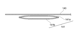
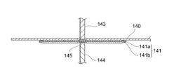
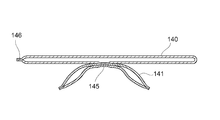
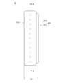
- 6 to 9 are schematic views for explaining the method of manufacturing the air cell according to the present embodiment. Among these, FIG. 6, FIG. 7, and FIG. 9 show the cross section of the sheet material which forms an air cell, and FIG. 8 shows the upper surface of the sheet material.
- a sheet made of a flexible resin material is formed into a cylindrical shape.
- one sheet may be folded in half and the one end side may be welded, or as shown in FIG. 6, two sheets 141a and 141b are overlapped, and both ends The sides may be welded.
- the side in the longitudinal direction is closed.
- both may be formed of the same resin material, and may be formed of different resin materials.
- the thickness is also preferably the same, but is not limited thereto.
- An opening for attaching the air supply ports 112 and 125 may be formed in advance in such a cylindrical body 141.
- step S11 a sheet member made of a flexible resin material and the cylindrical body molded in step S10 are laminated.
- FIG. 6 a mode that the cylindrical body 141 produced from two sheets of sheets 141a and 141b and another sheet member 140 are laminated is shown.
- the sheet member and the tubular body are welded in an elongated region along the longitudinal direction of the tubular body.
- the welding method is not particularly limited as long as sheet members made of a resin material can be partially welded.
- heat welding may be performed by sandwiching the sheet member 140 and the tubular body 141 with the heated molds 143 and 144, or high frequency welding may be performed.
- an elongated welded portion 145 formed by welding may be formed at a substantially central portion in the short direction of the cylindrical body 141.
- the sheet member is formed into a tubular shape. Specifically, as shown in FIG. 9, the sheet member 140 is folded in one direction, and the side 146 at one end is welded. Alternatively, another sheet member may be stacked on the sheet member 140, and the sides of both ends may be welded.
- the edge part of the folded sheet member 140 when the edge part of the folded sheet member 140 is welded from the upper and lower sides, a welding part will be in the state protruded outside like an ear.
- the end portions of the sheet members may be stacked such that the back side and the front side are in contact, and welding may be performed from the inside and the front side of the cylinder.
- the open end portions of the tubular sheet member 140 and the tubular body 141 are welded.
- the sheet member 140 formed into the bag shape becomes the main cell 110
- the tubular body 141 formed into the bag shape becomes the bag body 120 constituting the base cells 121, 122.
- the air cell 10 is completed by attaching the air supply port 112 to the main cell 110 and attaching the air supply port 125 to either of the base cells 121 and 122.
- the manufacturing method of the air cell 10 mentioned above is an example, and the order of each process may be replaced, or the inside of each process may be subdivided.
- the open end of the cylindrical body 141 may also be welded and made in advance as a bag.
- step S12 an operation of dividing the inner space into two regions (ie, base cells 121 and 122) by welding the substantially central portion of the cylindrical body 141, and integrating the sheet member 140 and the cylindrical body 141.
- the work may be performed separately.
- the work of separating the internal space of the tubular body 141 and the work of integrating the sheet member 140 and the tubular body 141 It has the advantage of being able to be completed at once.
- the position and means for connecting the tubular body 141 to the sheet member 140 can be appropriately selected.
- the tubular body 141 may be connected to the sheet member 140 by welding or the like at a plurality of locations in the weld portion formed in the tubular body 141.
- the two base cells 121 and 122 in which the flow of air is blocked are provided to the main cell 110, the local large main cell 110 is provided. Even when pressure is applied or the internal pressure in the main cell 110 is lowered, the main cell 110 can be supported by the base cells 121 and 122. Therefore, it is possible to realize a safe air cell 10 capable of preventing bottoming without increasing the total thickness. Further, in the present embodiment, the bottoming prevention function is realized by the structure of the air cell 10 instead of the bottoming prevention by the sensor or the electrical automatic control function, and an unexpected situation such as a power failure occurs. Even if it does, the air cell 10 can be used safely.
- the truss structure supporting the main cell 110 is formed by the two base cells 121 and 122, the load applied to the main cell 110 can be reduced to that of the two base cells 121 and 122. It can be dispersed in the direction. As a result, it is possible to reduce the contact pressure to the local area of the user's body and to improve the bedsore prevention effect.
- the sheet member 140 to be the main cell 110 and the tubular body 141 to be the bag body 120 are integrated by welding (see FIG. 9), the two bases
- the air cell 10 having a truss structure supporting the main cell 110 by the cells 121 and 122 can be manufactured in a simple process.
- the two base cells 121 and 122 are integrally formed by one bag body 120, the number of parts can be reduced. Therefore, the manufacturing process can be simplified, and maintenance during use of the air mattress can be easily performed.
- Air mattress can be realized.
- bedsores are at high risk for patients who can not move their body (it is difficult). Therefore, in designing the main cell, the following two aspects (1) and (2) are important. (1) Decreased physical function (mobility and activity, ie, being able to get out of bed, to be able to move on a bed, etc.) (2) Development of physical risk of body (with or without bone protrusion and contracture)
- the top surface of the mattress has a shape that does not inhibit the movement of the user according to the decrease in the physical function.
- muscles and fats that are cushioning materials of the body are lost due to medical treatment and complications, and bones are protruded or injured due to so-called sarcopenia (muscle loss) and hemorrhoids (loss of fat).
- the shape and structure of the air cell be set so as to prevent concentration of pressure on the bone projection site when contraction occurs.
- FIG. 10 is a cross-sectional view showing an air cell according to a second embodiment of the present invention.
- the air cell according to this embodiment has a truss structure in which the main cell is supported by two base cells as in the first embodiment, and the structure of the main cell on which the user's body can be directly placed is the above. It differs from the first embodiment.
- An air cell 20 shown in FIG. 10 is formed of a sheet material made of a flexible resin material such as urethane and the like, and three cells (main cell 210 and base cell 221 which expand in a cylindrical shape by enclosing air therein. , 222).
- the base cells 221 and 222 are parallel to the main cell 210 in a region on the air mattress side, like the base cells 121 and 122 in the first embodiment. It is attached to become.
- the flow of air is cut off between the main cell 210 and the base cells 221 and 222, and when air is sealed in the main cell 210 and the base cells 221 and 222, one of the two base cells 221 and 222 is used.
- a truss structure supporting the main cell 210 is formed.
- FIG. 10 illustrates a state in which each of the base cells 221 and 222 is in planar contact with the main cell 210 by applying a load to the air cell 20.
- the base cells 221 and 222 expand in a substantially cylindrical shape as in the case of the base cells 121 and 122 shown in FIG.
- the main cell 210 is provided with an air supply port for supplying air to the main cell 210, and any of the base cells 221, 222 has air in the base cells 221, 222.
- An air supply port for supplying air is provided.
- the size of the air cell 20 is not particularly limited as long as it can be adapted to a bed frame using an air mattress.
- the width W2 in the short side direction of the air cell 20 may be, for example, about 75 mm
- the thickness H2 (height from the lower end of the base cells 221 and 222 to the upper end of the main cell 210) may be, for example, about 130 mm.
- the thickness of the air cell 20 is determined so as to ensure a distance of 220 mm or more from the upper surface of the air mattress to the upper end of the side rail or the bed grip.
- the two base cells 221 and 222 are integrally formed by the bag body 220.
- the opposing sheet materials are welded to each other along the longitudinal direction at a substantially central portion in the short direction of the bag 220, and the bag 220 is separated into two base cells 221 and 222 by the welded portion 223.
- the bag body 220 is connected to the main cell 210 at the welding portion 223.
- a film-like member (so-called, fishing) 211 is provided so as to be oriented substantially parallel to the floor surface of the air mattress.
- the direction substantially parallel to the floor surface is the direction in which the film-like member 211 becomes substantially horizontal when the air cell 20 is placed on the floor surface.
- the film-like member 211 is welded at a position approximately half the thickness of the main cell 210, and connects mutually opposing areas of the inner circumferential surface.
- FIG. 11 is a side view showing an air cell according to a third embodiment of the present invention.
- FIG. 12 is a cross-sectional view taken along a line BB in FIG.
- the air cell according to this embodiment has a truss structure in which the main cell is supported by two base cells as in the first embodiment, and the structure of the main cell on which the user's body can be directly placed is the above. It differs from the first embodiment.
- the air cell 30 shown in FIG. 11 is formed of a sheet material made of a flexible resin material such as urethane and the like, and three cells (main cell 310 and base cell 321 which expand in a cylindrical shape by enclosing air inside) , 322).
- the base cells 321 and 322 are integrally formed by the bag body 320 like the base cells 121 and 122 in the said 1st Embodiment.
- the structure of the base cells 321 and 322 and the connection structure of the base cells 321 and 322 to the main cell 310 are the same as those of the base cells 121 and 122 in the first embodiment.
- the main cell 310 is provided with an air supply port for supplying air to the main cell 310, and any of the base cells 321 and 322 has an air supply port for the base cells 321 and 322.
- An air supply port for supplying air is provided.
- the size of the air cell 30 is not particularly limited as long as it can be adapted to a bed frame using an air mattress.
- the width W3 in the short side direction of the air cell 30 may be, for example, about 80 mm
- the thickness H3 (height from the lower end of the base cells 321 and 322 to the upper end of the main cell 310) may be about 160 mm.
- the thickness of the air cell 20 is determined so as to ensure a distance of 220 mm or more from the upper surface of the air mattress to the upper end of the side rail or the bed grip.
- a film-like member (so-called, fishing) 311 is provided, which has a direction substantially orthogonal to the floor surface of the air mattress and is bridged in a bellows shape.
- the direction substantially orthogonal to the floor surface is the direction in which the film-like member 311 is in a standing state when the air cell 30 is placed on the floor surface.
- the film-like members 311 are alternately welded to the regions 312 and 313 facing each other on the inner peripheral surface of the main cell 310.
- the main cell 310 is prevented from expanding in the lateral direction, and the amount of compression in the thickness direction of the main cell 310 is suppressed. can do.
- the pressure is dispersed in the longitudinal direction of the main cell 310, so the contact pressure at each part of the user's body is reduced, and the bedsore prevention effect is achieved. Can be enhanced.
- base cells 321 and 322 are formed by welding the substantially central portion of bag body 320 alone along the longitudinal direction, and thereafter, a plurality of locations in the weld portion of bag body 320 are welded to main cell 310.
- the bag body 320 may be connected to the main cell 310.
- the main cell 310 is slightly distorted in the longitudinal direction when air is introduced into the inside due to the presence of the film-like member 311, so a part in the welded part is more than connecting the entire welded part of the bag body 320 to the main cell 310.
- the shape of the bag body 320 can be maintained substantially straight along the longitudinal direction, and the main cell 310 can be stably supported.
- FIG. 13 is a cross-sectional view showing an air cell according to a fourth embodiment of the present invention.
- FIG. 14 is an example of a top view of the air cell shown in FIG.
- the air cell according to this embodiment has a truss structure in which the main cell is supported by two base cells as in the first embodiment, and another base cell is provided on the upper surface of the main cell. Is different from the first embodiment.
- An air cell 40 shown in FIG. 13 is formed of a sheet material made of a flexible resin material such as urethane and the like.
- a plurality of cells (main cell 410, base cell 421) which expand in a cylindrical shape by enclosing air therein.
- the upper cell group 430 A is formed by the bag body 420 in the same manner as the base cells 121 and 122 in the first embodiment, and The structure of the base cells 421 and 422 and the connection structure of the base cells 421 and 422 with the main cell 410 are the same as those of the base cells 121 and 122 in the first embodiment.
- FIG. 13 shows a state in which each of the base cells 421 and 422 is in planar contact with the main cell 410 by applying a load to the air cell 40.
- the base cells 421 and 422 are expanded in a substantially cylindrical shape, similarly to the base cells 121 and 122 shown in (a) of FIG.
- the main cell 410 is provided with an air supply port for supplying air to the main cell 410, and any of the base cells 421 and 422 has an air supply port for the base cells 421 and 422.
- An air supply port for supplying air is provided.
- the size of the air cell 40 is not particularly limited as long as it can be adapted to a bed frame using an air mattress.
- the width W4 in the short side direction of the air cell 40 may be, for example, about 80 mm
- the thickness H4 (height from the lower end of the base cells 421 and 422 to the upper end of the upper cell group 430A) may be about 130 mm.
- the thickness of the air cell 40 is determined so as to ensure a distance of 220 mm or more from the upper surface of the air mattress to the upper end of the side rail or the bed grip.
- the upper cell group 430A is formed of a sheet material made of a flexible resin material, and includes a plurality of cells 431a to 435a and 431b to 435b each of which expands in a cylindrical shape by enclosing air therein.
- Such an upper cell group 430A is integrally formed by one bag body 430, and in the region on the opposite side of the base cells 421 and 422 in the outer peripheral surface of the main cell 410, substantially in the longitudinal direction of the main cell 410. It is attached to be parallel.
- FIG. 13 shows a state in which each of the cells constituting the upper cell group 430A is in planar contact with the main cell 410 by applying a load to the air cell 40. When no load is applied to the air cell 40, each of the cells constituting the upper cell group 430A swells in a substantially cylindrical shape, as with the base cells 121 and 122 shown in (a) of FIG.
- the cells 431a to 435a and 431b to 435b have a plurality of bag bodies 430 (five in FIG. 14) by narrowing at a plurality of locations on the longitudinal side of the bag body 430 having a substantially rectangular shape when viewed from the upper surface. Divided into two regions 431 to 435, and approximately the center of each region 431 to 435 is welded along the longitudinal direction, and the internal space of each region 431 to 435 is separated into two by welding portions 431c to 435c. It is done.
- the diameter of each of the cells 431a to 435a and 431b to 435b is smaller than the diameter of the main cell 410, for example, about half the diameter of the main cell 410.
- Air can flow between the cells 431a to 435a and 431b to 435b. Further, air may be allowed to flow between the upper cell group 430A and the main cell 410, or the air may be shut off. In the former case, the internal pressure of the upper cell group 430A and the main cell 410 is substantially uniform. In the latter case, it is necessary to provide an air supply port for supplying air to the upper cell group 430A separately from the main cell 410.
- the ratio of the length in the longitudinal direction of each of the cells 431a to 435a and 431b to 435b is not particularly limited, and may be appropriately determined according to the position in the air mattress in which the air cell 40 is disposed. For example, when the air cell 40 is disposed near the center of the air mattress, the cells 433a and 433b near the center may be made longer so that the buttocks of the user get on sufficiently.
- the user's body carried on the air cell 40 can be It can be supported in a larger area so as to wrap around.
- the contact pressure on each part of the body can be reduced, and the bedsore prevention effect can be improved. That is, in the air cell 40, a low pressure in the air cell does not reduce the contact pressure to the body, but a plurality of cells cooperate to support the body to reduce the contact pressure to the body. There is. As a result, it is possible to prevent a situation in which a part of the body locally sinks in the low pressure air cell and the contact pressure becomes rather high due to the hammock phenomenon.
- the bag 430 is divided into five regions 431 to 435 in the longitudinal direction in FIG. 11, the number of regions is not limited to five. It may be roughly divided (for example, three) or more finely (for example, six or more). Further, in FIG. 11, the five regions 431 to 435 are connected at the center and integrated as the bag 430, but the five regions 431 to 435 may be completely separated to form five bags. . Conversely, the internal space of the bag 430 may be simply divided into two along the longitudinal direction without dividing the bag 430 in the longitudinal direction.
- the method of manufacturing the air cell 40 is not particularly limited.
- the cells 431a to 435a and 431b to 435b are formed by welding the substantially central portion of the bag 430 in a line separately from the main cell 410, and then the bag 430 is assembled by the welding or the like. It may be connected to 410.
- the welds 431 c to 435 c may be formed in the bag 430 and integrated with the bag 430 at the same time.
- the cells 431 a to 435 a and 431 b to 435 b are relatively relatively centered on the welding portions 431 c to 435 c It can move freely as compared to the case of connecting in a plane to 410. Thereby, even if the user's body is slightly twisted, the cells 431a-435a, 431b-435b flexibly follow and the cells 431a-435a, 431b-435b support the user's body in a large area.
- the air outlet between the main cell 410 and the bag 430 is provided with an opening at each of the areas 431 and 435 at both ends, and an opening is provided at two places of the main cell 410, and the bag 430 is main
- the openings provided in the regions 431 and 435 may be integrated with the openings provided in the main cell by welding.
- the openings are provided in advance in each bag and the main cell 410 is formed.
- the openings are provided as many as the number of bag bodies, and when welding each bag body to the main cell 410, the air vents are formed by integrating the openings provided in each bag body with the openings provided in the main cell by welding. It should be formed.
- FIG. 15 is a cross-sectional view showing an air cell according to a fifth embodiment of the present invention.
- the air cell according to this embodiment has a truss structure in which the main cell is supported by two base cells as in the first embodiment, and the structure of the main cell on which the user's body can be directly placed is the above. It differs from the first embodiment.
- An air cell 50 shown in FIG. 15 is formed of a sheet material made of a flexible resin material such as urethane, and four cells (main cells 511 and 512 and a base that expand in a cylindrical shape by enclosing air inside) Cells 521, 522).
- the base cells 521 and 522 are, similarly to the base cells 121 and 122 in the first embodiment, a center (welded portion) in the area on the air mattress side of the outer peripheral surface of the main cells 511 and 512. 523).
- Air can flow between the main cells 511 and 512 and between the base cells 521 and 522, respectively.
- the flow of air is blocked between the main cells 511 and 512 and the base cells 521 and 522. Therefore, when air is enclosed in the main cells 511 and 512 and the base cells 521 and 522, respectively, a truss structure is formed in which the main cells 511 and 512 and the portions of the body they support are supported by the two base cells 521 and 522. Be done.
- an air supply port for supplying air to the main cells 511, 512 is provided in one of the main cells 511, 512, and one of the base cells 521, 522 is An air supply port for supplying air to the base cells 521, 522 is provided.
- the size (width W5 and thickness H5) of the air cell 50 is not particularly limited as long as it can be adapted to a bed frame using an air mattress.
- manufacturers of nursing beds often define the conditions of various accessories (special bed accessories) used in combination with their own products.
- the mattress which can be used in combination with the bed frame (side rail) of the company is the thickest replacement mattress It is assumed that the accessory is configured to conform to a mattress thickness of 16 cm or less based on the mattress of the specification.
- the thickness H5 (that is, the thickness of the air mattress) of each air cell 50 may be about 75 to 80 mm. Since the thickness of a standard mattress is about 75 mm to 80 mm, this can reduce the total thickness of a standard mattress and an overlaid air mattress to 16 cm or less.
- the main cells 511 and 512 are integrally formed by the bag body 510. Further, the base cells 521 and 522 are integrally formed by the bag body 520. These bags 510, 520 are integrated at a weld 523 formed along the longitudinal direction of the air cell 50, and the inner space is divided into two regions. That is, the main cells 511 and 512 are formed by dividing the inside of the bag body 510 by the welding part 523, and the base cells 521 and 522 are formed by dividing the inside of the bag body 520 by the welding part 523.
- the method of manufacturing the air cell 50 is not particularly limited.
- two bag bodies 510 and 520 may be overlapped, and a substantially central portion may be integrally welded along the longitudinal direction.
- the respective welded portions may be connected in whole or in part.
- the main cells 511 and 512 arranged in parallel can support a wider area so as to wrap the user's body placed on the air cell 50.
- the contact pressure on each part of the body can be reduced, and the bedsore prevention effect can be improved.
- the pressure of the user's body applied to the main cells 511 and 512 can be dispersed in a plurality of directions by the base cells 521 and 522. In other words, the user's body sunk into the main cell 511, 512 is widely supported by the reaction force received from the base cell 521, 522, the contact pressure to the local part of the body is reduced, and the bedsore prevention effect Can be enhanced.
- the thickness H5 of the entire air cell 50 can be made thinner than that of a general air cell, so that it conforms well to the JIS standard (JIS 9254: 2009) It is also suitable for use as an overlay on top of one another.
- one set of main cells 511 and 512 is provided for one air cell 50.
- a plurality of sets of main cells 511 and 512 are provided in the air cell 50. It may be arranged along the longitudinal direction. As an example, a pair of main cells 511, 512 having a length of about half the length of the air cell 50 is disposed at the central portion in the longitudinal direction of the air cell 50, one side of the length of the air cell 50 on both sides thereof. Two sets of main cells 511 and 512 each having a length of about 4 may be arranged.
- the air cells according to the first to fifth embodiments described above can constitute an air mattress by one type or in combination with other types of air cells.
- the air mattress using the air cell according to the first to fifth embodiments may be a stationary type that maintains the air pressure in the air cell at a predetermined value, or a pressure switching type that periodically changes the air pressure in the air cell. It is good and you may combine both.
- a configuration example of an air mattress in which a stationary type and a pressure switching type are combined will be described.
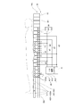
- FIG. 16 is a side view showing an air mattress according to a sixth embodiment of the present invention.
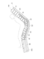
- FIG. 17 is a side view of the same air mattress, showing a state of raising the back and knees (lifting the knee portion like a mountain).
- the air mattress 100 includes a plurality of types of air cells 15, 30, 40, and an air conditioning system A that periodically changes the internal pressure of some of the air cells 30.
- the air mattress 100 is usually used side by side on the bed bottom B.
- the bed bottom B is divided into four parts of a back bottom B1, a hip bottom B2, a leg bottom B3, and a knee bottom B4.
- Each bottom is a plate-like member and may be partially meshed for ventilation.
- the back bottom B1 is usually a portion on which the head to back of the user can be placed.
- the waist bottom B2 is usually a portion on which the user's waist and buttocks are placed, and is further divided into a plurality of (eight in FIG. 16 and FIG. 17) portions in the longitudinal direction of the bed bottom B.
- a portion of the waist bottom B2 on the head side from the central portion and the spine bottom B1 are raised around the substantially central portion of the waist bottom B2 (see FIG. 17).
- the leg bottom B3 is usually a portion on which the user's thighs and knees can be placed.
- the knee bottom B4 is usually a portion on which the lower leg from the user's knee can be placed. At the time of knee lifting, the connecting portion between the leg bottom B3 and the knee bottom B4 is raised so as to form a mountain (see FIG. 17).
- a gap is provided between the hip bottom B2 and the leg bottom B3 and between the leg bottom B3 and the knee bottom B4 so that the bottoms do not interfere with each other when raising the back or raising the knee.
- segmentation number of the bed bottom B, the ratio of the length of each bottom, etc. it is not limited to what is illustrated in FIG. 16, FIG.
- a plurality of (four in FIG. 16) air cells 15 having a simple cylindrical shape are arranged in order from the end on the head side (right side in the drawing), and the third embodiment.
- An air cell 40 is disposed in parallel with the short side direction of the bed bottom B.
- a plurality of air cells 40A are disposed in parallel with the longitudinal direction of the bed bottom B at the end of the foot side (left side in the drawing) of the air mattress 100.
- the air cell 15 and four air cells 30 are arranged in order from the head side on the back bottom B1.
- the air cell 15 having a general shape (tubular shape) is In the same manner as in the first to third embodiments, an air cell provided with a base cell may be arranged.
- the arrangement and the number of the air cells 15 and the air cells 30 in the back bottom B1 are not limited to the above.
- the air cell for example, the air cell 15
- the air cell 15 used as a stationary type is disposed, and the foot side of the back bottom B1. Since a trunk such as the back of the user is placed in the area, an air cell (for example, an air cell 30) used as a pressure switching type may be disposed.
- the number of various air cells may be approximately the same or different.
- the bag 430 forming the upper cell group 430A may be divided into five regions 431 to 435, or the regions may be divided. The number may be changed, or the region may not be divided in the longitudinal direction of the air cell 40.
- the posture of the user is provided by arranging the air cell 40 having the upper cell group 430A on both sides of a portion (substantially central portion) which is bent when raising the spine in the waist bottom B2.
- air cells arranged to maintain the posture of the user and prevent misalignment are also called anchor cells.
- the anchor cell is used as a stationary type that maintains the internal pressure set according to the weight of the user and the like.
- two air cells 40 are disposed on the head side and one air cell 40 is disposed on the foot side with respect to the approximate center of the waist bottom B 2.
- one air cell 40 may be disposed on each side of the approximate center of the waist bottom B2.
- anchor cells may be arranged on both sides of the portion to be bent at the time of raising the back.
- anchor cells may be arranged on both sides of the divided portion of the bed bottom.
- the air cell (for example, air cell 30) used as a pressure switching type
- Three air cells 30 and two air cells 40 are sequentially disposed on the leg bottom B3.
- One air cell 40 and a plurality of air cells 40A are disposed on the knee bottom B4.
- the bag 430 forming the upper cell group 430A is divided into five regions 431 to 435. It is preferable that the number of divisions of the area is changed, or that the area is not divided in the longitudinal direction of the air cell 40. Since the vicinity of the boundary between the leg bottom B3 and the knee bottom B4 is the highest part when the knee is lifted, the user's leg is likely to be displaced in the direction of the waist. Therefore, in this embodiment, the air cell 40 is disposed as an anchor cell on both sides of the boundary between the leg bottom B3 and the knee bottom B4.
- FIGS. 16 and 17 two air cells 40 are disposed on the leg bottom B3 side and one air cell 40 is disposed on the knee bottom B4 side
- the arrangement of the air cells 40 is not limited to this.
- one anchor cell or two anchor cells may be disposed on both sides of the boundary between the leg bottom B3 and the knee bottom B4.
- the anchor cells may be arranged to be in contact with both the back of the user and the back of the knee.
- an air cell (for example, an air cell 30) used as a pressure switching type is disposed in a region of the leg bottom B3 other than the region where the anchor cell is disposed.
- the air cell 40A disposed on the foot side (left side of the figure) of the knee bottom B4 has the upper portion on the main cell in addition to the main cell and the base cell as in the fourth embodiment (see FIGS. 13 and 14). It has a cell group.
- the longitudinal length of the air cell 40A is preferably shorter than the longitudinal length of the air cells 15, 30, 40 disposed in other portions.
- the division number of the upper cell group in the longitudinal direction of the air cell 40A is not particularly limited, and in FIG. 16 and FIG. 17, the one divided into three regions is shown. In the other end region (foot region) of the air mattress 100, since it is considered that the user's weight is not extremely concentrated, an air cell used as a stationary type is disposed.
- the air supply system is divided between the air cell 40 disposed in the peripheral area of the portion of the waist bottom B2 that is bent by raising the back and the air cell disposed in the other area, and the air flow is distributed. Is blocked. This is to prevent the escape of air from air cells disposed in this area to air cells in other areas, since the weight of the user is concentrated in the peripheral area of the portion which is bent by the back elevation. More preferably, an air cell 15 disposed in the back bottom B1, an air cell 30 disposed in the back bottom B1, the waist bottom B2, and the leg bottom B3 and an air cell 40 disposed in the waist bottom B2 for each region.
- the air supply system may be divided between the air cell 40 disposed in the leg bottom B3 and the knee bottom B4 and the air cell 40A disposed in the knee bottom B4 to block the flow of the air.
- the air cells may be used as a stationary type, and air may flow between adjacent air cells of the same type.
- the air cell 15 disposed on the back bottom B1, the air cell 40 disposed on the hip bottom B2, the leg bottom B3, and the knee bottom B4, and the air cell 40A disposed on the knee bottom B4 The air set at a predetermined pressure is filled and maintained while the air mattress 100 is in use. In particular, since the user's head is placed on the air cell 15 disposed on the back bottom B1, the air cell 15 is maintained at a constant value in order to prevent the user from getting sick. Further, for the base cells of the air cell 30 and the air cells 40 and 40A, the internal pressure necessary to support the main cell is set and maintained separately from the internal pressure of the main cell.
- Each base cell 321, 322 of the air cell 30 disposed in the back bottom B1, the waist bottom B2, and the leg bottom B3 is filled with air of a preset internal pressure before using the air mattress 100, and the air mattress 100 Maintained while in use.
- the internal pressure of each main cell 310 (see FIG. 11) of the air cell 30 periodically changes due to the operation of the air conditioning system A while the air mattress 100 is in use.
- the air conditioning system A includes an air cell group of a first air system connected to the flow path a1, an air cell group of a second air system connected to the flow path a2, and a third connected to the flow path a3. The operation of depressurizing and returning to the reference internal pressure set according to the weight of the user etc. is repeated for the air cells of the three air system.
- the configuration of the air adjustment system A is not particularly limited.
- the air adjustment system A is provided with one pump and a rotary valve having a plurality of intake and exhaust ports, and connected to the flow paths a1, a2, and a3 at the intake and exhaust ports of the rotary valve to operate the rotary valve. It is also possible to sequentially switch the air supply to the air cell group of each system and the exhaust by controlling.
- an electromagnetic valve may be connected to each of the flow paths a1, a2, and a3, and the operation of the electromagnetic valves may be controlled so that the three flow paths a1, a2, and a3 are opened and closed in a predetermined order. Also good.
- the air mattress 100 on which the user's upper trunk (the part excluding the head and the four limbs) and the lower leg can be placed since the air cells 30, 40, 40A having the base cells in which the flow of air is blocked are arranged, even if the user's weight is concentrated on a part of the air mattress 100, the bottoming may be prevented.
- the load on the air cell can be distributed in multiple directions. Therefore, since it is not necessary to thicken the air cell for the purpose of preventing bottoming, it is possible to easily conform to the JIS standard regarding thickness. That is, consistency with general-purpose parts (such as side rails) around the bed can be ensured, and the air mattress 100 can be used safely.
- the internal pressure of the air cell is not lowered but the pressure distribution is realized by the structure of the air cell, and the contact pressure on the user's body is reduced, so that the hammock phenomenon can be suppressed.
- bed sores occur at individual bone projecting sites on the body surface.
- bed slippage is likely to occur in the trunk of the trunk where the weight of the entire body tends to gather, that is, the spine and pelvis of the trunk.
- the air cells 30, 40, 40A having a pressure distribution function are disposed in the area where the user's torso and pelvis can be placed. It can be reduced.
- the bottoming prevention effect and the pressure distribution effect are generated by the structure of the individual air cells, the user safely uses the air mattress 100 even in the event of an unexpected situation such as a power failure, for example. , These effects can be obtained.
- the internal pressure of the air cell 30 is periodically changed in the area excluding the area at both ends in the longitudinal direction of the air mattress 100 (specifically, the area in which the anchor cell is not disposed). Therefore, the contact pressure to each part of the user's body can be changed as needed to prevent bedsores.
- the truss structure of the base cells 321 and 322 can disperse the load on the air cell in a plurality of directions. In other words, the contact pressure received by the user from the air cell can be reduced. That is, in the present embodiment, in addition to the contact pressure reducing effect similar to that of a general pressure switching type air mattress, the body pressure dispersing effect by the base cells 321 and 322 can be obtained.
- reperfusion injury refers to damage to skin tissue caused by inflowing blood when blood flow interrupted by pressure on the skin is recovered.
- the contact pressure applied to the body is high because the area of the air cell of the system from which the air is exhausted is reduced.
- the contact pressure when switching the internal pressure is twice as large as that when the pressure switching is not performed.
- pressure switching air mattresses currently on the market are mainly based on triple pressure switching, and some have increased the number of systems as a risk countermeasure.
- the pressure applied to the air cells of the other systems is up to 150% (3/2 times) compared to the case where the pressure is applied evenly to the three lines. That is, as compared with the case where the pressure switching is not performed, the pressure is applied excessively.
- One possible way to reduce the pressure applied to air cells of other systems is to increase the number of air supply systems to the air cells. For example, when the number of air supply systems is four, the pressure applied to the air cells of the other systems is up to about 133% (4/3 times) as compared with the case where the pressure is uniformly applied to the four systems. It becomes.
- each air cell has a body pressure dispersing function by the truss structure, even if the pressure applied to the air cell of another system is increased by pressure switching, the structure of the air cell itself By the action, the contact pressure to which the body is subjected can be reduced and a stable blood flow can be secured. Therefore, it is possible to suppress the possibility of reperfusion injury without increasing the air supply system more than necessary.
- the air mattress 100 between the plurality of areas constituting the air mattress 100, that is, one end area where the head of the user is disposed, and the other end where the foot of the user is disposed. Since the air supply system is made independent between the regions, the region of the substantially central portion of the air mattress 100 which is folded in the back elevation, and the regions which are folded in the knee elevation, the flow between the air cells is interrupted. Even when the weight of the user is concentrated on a part of the air mattress 100, it is possible to suppress the influence on the air cells arranged at other parts. For example, when the air mattress 100 is raised up (see FIG.
- the air in these air cells 40 flows out to the air cells of other parts. There is nothing to do. Therefore, when raising the back, the air in the air cell arranged in the waist bottom B2 escapes to the air cell in another part, and the air cell of the waist bottom B2 bottoms up, or the bottomed air cell of the waist bottom B2 When air is supplied to the air, it is possible to avoid the situation where the air escapes to the air cell of the other part and the air cell of the other part is expanded.
- the air cell 40 provided with the upper cell group 430A is disposed on both sides of the bent portion of the waist bottom B2, the user's buttocks are wrapped by the upper cell group 430A when raised. As supported. Therefore, it is possible to prevent so-called forward displacement in which the user's body is displaced to the foot side, and it is possible to lift the user's upper body without difficulty.
- the air cell 40A is disposed on the foot side of the knee bottom B4 in parallel with the longitudinal direction of the air mattress 100, so that the user's foot is wrapped in the upper cell group 430A of the air cell 40A. It is supported by a large area. Therefore, the contact pressure to each part of the body surface can be reduced.
- FIG. 18 is a schematic view showing a configuration example of an air adjustment system according to a seventh embodiment of the present invention.
- air supply and discharge to the air cells grouped into a plurality of systems are repeated at a predetermined cycle.
- such an operation can be realized by control of a rotary valve or control of a plurality of solenoid valves respectively connected to a plurality of systems.
- the air from the air cell that was just at the exhaust timing Will continue to escape. If the control stop state continues for a long time, air may completely escape from the air cell, which may cause bottoming.
- the air mattress 100 described in the sixth embodiment that is, an air conditioning system for supplying and discharging air to an air mattress combining a pressure switching type and a stationary type will be described.
- the air adjustment system according to the present embodiment can also be applied to a general pressure switching type air mattress.
- the air adjustment system 70 includes a pump unit 71 that supplies air into each air cell that constitutes an air mattress, and a rotary valve that switches the supply and exhaust of air to each air cell. 72 and electromagnetic valves 73 and 74.
- the air adjustment system 70 may further include a pressure sensor 75 that detects the pressure in the rotary valve 72.
- the pump unit 71 includes an air pump 711 that ejects air, and a control unit 712 that controls the operation of the air pump 711 and the rotary valve 72 based on the pressure value detected by the pressure sensor 75.
- the rotary valve 72 is provided with a plurality of air inlets and outlets connected to a predetermined pipe.
- the air introduction port 720 is connected to a flow path f 1 for introducing the air jetted from the air pump 711 into the rotary valve 72.
- the air supply / discharge port 721 is connected to a flow path a1 for circulating air between the air cell group (the air cell 30) of the first air system (see FIG. 16) and the main cell 310 (see FIG. 16).
- the air supply / discharge port 722 is connected to a flow path a2 for circulating air between the air cell group (air cell 30) of the second air system and the main cell 310 of the air cell group.
- the air supply / discharge port 723 is connected to a flow path a3 for circulating air between the air cell group of the third air system (the air cell 30) and the main cell 310 of the air cell group.
- the air supply port 724 is connected with a flow path f2 for supplying air to the air cells in the head and the foot (air cells 15 disposed in the back bottom B1 and air cells 40A disposed in the knee bottom B4).
- a flow path f3 for supplying air to the anchor cell (the air cell 40 disposed at the waist bottom B2, the leg bottom B3 and the knee bottom B4) and the base cells 321 and 322 of the air cell 30 in the air supply port 725 Is connected.
- a flow path f4 for opening the air to the atmosphere is connected to the exhaust port 726.
- the exhaust port 727 is connected to a flow path f5 for circulating air between itself and the pressure sensor 75.
- the air introduction port 720 and the air supply port 724 are connected.
- the air introduction port 720 and the air supply port 725 are connected.
- air is supplied from the flow paths f2 and f3 until each air cell has a predetermined internal pressure.
- the air supply ports 724 and 725 are closed, and air is not supplied to the air cell from the flow paths f2 and f3 and the air is not discharged from each air cell. .
- the air inlet 720 and the air outlet 721 are connected, and when air is discharged from the air cell group, the air is discharged.
- the port 721 and the exhaust port 726 are connected.
- the air inlet 720 and the air outlet 722 are connected, and when air is discharged from the air cell group, the air outlet 722 And the exhaust port 726 are connected.
- the air inlet 720 and the air outlet 723 are connected, and when air is discharged from the air cell group, the air outlet 723 And the exhaust port 726 are connected.
- air is supplied from the flow paths a1, a2, and a3 until the air cells of each air cell group have a predetermined internal pressure.
- each of the air supply and exhaust ports 721, 722, and 723 is connected to the air introduction port 720 and the exhaust port 726 in a predetermined order, and adjustment of the internal pressure is repeated for each air cell group.
- the flow path f4 connected to the exhaust port 726 discharges the air flowing into the rotary valve 72 from any of the air cells of the first air system, the second air system, and the third air system to the atmosphere.
- the solenoid valve 73 is provided in the flow passage f4 and is set to open the valve to flow air during energization and close the valve to close the flow passage f4 when the energization is shut off.
- the solenoid valve 74 is provided in the flow passage f1 and is set to open the valve to flow air during energization and close the valve to close the flow passage f1 when the energization is shut off. Therefore, while any one of the air supply and exhaust ports 721, 722, 723 and the air supply ports 724, 725 is connected to the air inlet 720, a power failure occurs and the operation of the pump unit 71 is stopped. Also, since the flow of electricity to the solenoid valve 74 is cut off and the flow path f1 is closed, the air does not flow back to the air pump 711 from any of the air cells constituting the air mattress, and The internal pressure can be maintained. Although the solenoid valve 74 is not essential, it is preferable to provide it as a safer and more reliable measure in consideration of a long-term power failure.
- the air mattress can be used. Since the exhaust from each air cell which comprises can be prevented, it becomes possible to use an air mattress safely and safely, without fear of bottoming.
- the air adjustment system according to the present embodiment can be applied not only to the air mattress 100 shown in FIG. 16 but also to various air mattresses.
- the air adjustment system according to the present embodiment can also be applied to an air blow-type air mattress other than a general pressure switching-type air mattress.
- the air-blowing type air mattress is a type of mattress that escapes moisture and prevents stuffiness by constantly exhausting air from the surface of the air mattress.
- an exhaust port for air injection may be provided in the rotary valve, and a flow path connecting the exhaust port with the air introduction port 720 may be formed inside the rotary valve.
- the present invention described above is not limited to the above first to seventh embodiments, and various components can be obtained by appropriately combining a plurality of components disclosed in the above first to seventh embodiments.
- the invention can be formed. For example, some components may be excluded from all the components shown in the first to seventh embodiments, or the components shown in the first to seventh embodiments may be formed appropriately. You may combine and form.
- An air conditioning system for adjusting the internal pressure of the plurality of air cells in an air mattress in which a plurality of air cells are provided side by side, An air pump for injecting air into at least one of the plurality of air cells;
- Rotary valve for switching the internal pressure of at least one of the air cells by performing supply of air injected into the air cell from the air pump and exhaust of the air at a predetermined cycle from the at least one air cell to the rotary valve
- a solenoid valve provided in a flow path for discharging the air that has flowed to the outside, the valve being opened during energization and set so as to close the valve when energization is shut off;
- Air conditioning system with
- a second solenoid valve provided in a flow passage for introducing air from the air pump to the rotary valve, the valve being opened during energization and set to close the valve when the energization is shut off.
- Air cell 100 air mattress 110, 210, 310, 410, 511, 512 main cell 111 fixed portion 112 air supply port 120, 220, 320, 420, 430, 510, 520 Bag body 121, 122, 221, 222, 321, 322, 421, 422, 521, 522 Base cell 123, 145, 223, 423, 431c to 435c, 523 Welded part 124 Gap area 125 Air supply port 130 Bed frame 140 Sheet member 141 Tubular body 141a, 141b Sheet 143, 144 Mold 146 Side 211, 311 Film-like Member 312 area 430A upper cell group 431, 435 area 431a to 435a, 431b to 435b cell 70 air adjustment system 71 pump unit 72 rotary valve 73, 74 solenoid valve 75 pressure sensor 711 air pump 712 control unit 720 air inlet 721, 722, 721 723 Air outlet 724, 725 Air inlet 726, 727 Air outlets
Landscapes
- Health & Medical Sciences (AREA)
- Nursing (AREA)
- Life Sciences & Earth Sciences (AREA)
- Animal Behavior & Ethology (AREA)
- General Health & Medical Sciences (AREA)
- Public Health (AREA)
- Veterinary Medicine (AREA)
- Invalid Beds And Related Equipment (AREA)
- Mattresses And Other Support Structures For Chairs And Beds (AREA)
Abstract
L'invention concerne une chambre à air et analogue qui peut empêcher un matelas pneumatique de s'affaisser et qui offre un bon effet de prévention des escarres sans dépasser l'épaisseur des matelas pneumatiques classiques. Une chambre à air, constituant un matelas pneumatique, qui est utilisée avec l'air qu'elle renferme comprend une première chambre qui est formée à partir d'un matériau en feuilles comprenant un matériau en résine souple et qui se gonfle jusqu'à obtention d'une forme cylindrique en enfermant de l'air à l'intérieur, et des deuxième et troisième chambres qui sont formées à partir d'un matériau en feuilles comprenant un matériau en résine souple et qui se gonflent jusqu'à obtention d'une forme cylindrique en enfermant de l'air à l'intérieur. Les deuxième et troisième chambres, qui sont fixées parallèlement à la direction longitudinale de la première chambre, sont disposées sur une région de la surface périphérique extérieure de la première chambre, sur la face inférieure du matelas pneumatique, et lorsque le flux d'air est bloqué entre la première chambre et les deuxième et troisième chambres et que l'air est piégé par les première, deuxième et troisième chambres, la première chambre est supportée par les deuxième et troisième chambres.
Applications Claiming Priority (2)
| Application Number | Priority Date | Filing Date | Title |
|---|---|---|---|
| JP2017-198188 | 2017-10-12 | ||
| JP2017198188 | 2017-10-12 |
Publications (1)
| Publication Number | Publication Date |
|---|---|
| WO2019073624A1 true WO2019073624A1 (fr) | 2019-04-18 |
Family
ID=66100691
Family Applications (1)
| Application Number | Title | Priority Date | Filing Date |
|---|---|---|---|
| PCT/JP2018/014022 Ceased WO2019073624A1 (fr) | 2017-10-12 | 2018-03-31 | Chambre à air et matelas pneumatique |
Country Status (1)
| Country | Link |
|---|---|
| WO (1) | WO2019073624A1 (fr) |
Cited By (1)
| Publication number | Priority date | Publication date | Assignee | Title |
|---|---|---|---|---|
| GB2619263A (en) * | 2022-04-05 | 2023-12-06 | Squirrel Medical Ltd | A mattress and a method for its operation |
Citations (6)
| Publication number | Priority date | Publication date | Assignee | Title |
|---|---|---|---|---|
| JPS64929U (fr) * | 1987-06-23 | 1989-01-06 | ||
| US5651151A (en) * | 1993-10-19 | 1997-07-29 | Huntleigh Technology Plc | Alternating pressure pad |
| WO2009044515A1 (fr) * | 2007-10-02 | 2009-04-09 | Molten Corporation | Système de commande d'un matelas pneumatique |
| JP2011160894A (ja) * | 2010-02-05 | 2011-08-25 | Paramount Bed Co Ltd | ポンプ内蔵エアマットレス |
| US20140237727A1 (en) * | 2013-02-25 | 2014-08-28 | Zhejiang Natural Travel Goods Co., Ltd. | Air mattress and inflatable product |
| WO2015162667A1 (fr) * | 2014-04-21 | 2015-10-29 | 株式会社 ハイビックス | Cellules pour matelas pneumatique, et matelas pneumatique |
-
2018
- 2018-03-31 WO PCT/JP2018/014022 patent/WO2019073624A1/fr not_active Ceased
Patent Citations (6)
| Publication number | Priority date | Publication date | Assignee | Title |
|---|---|---|---|---|
| JPS64929U (fr) * | 1987-06-23 | 1989-01-06 | ||
| US5651151A (en) * | 1993-10-19 | 1997-07-29 | Huntleigh Technology Plc | Alternating pressure pad |
| WO2009044515A1 (fr) * | 2007-10-02 | 2009-04-09 | Molten Corporation | Système de commande d'un matelas pneumatique |
| JP2011160894A (ja) * | 2010-02-05 | 2011-08-25 | Paramount Bed Co Ltd | ポンプ内蔵エアマットレス |
| US20140237727A1 (en) * | 2013-02-25 | 2014-08-28 | Zhejiang Natural Travel Goods Co., Ltd. | Air mattress and inflatable product |
| WO2015162667A1 (fr) * | 2014-04-21 | 2015-10-29 | 株式会社 ハイビックス | Cellules pour matelas pneumatique, et matelas pneumatique |
Cited By (1)
| Publication number | Priority date | Publication date | Assignee | Title |
|---|---|---|---|---|
| GB2619263A (en) * | 2022-04-05 | 2023-12-06 | Squirrel Medical Ltd | A mattress and a method for its operation |
Similar Documents
| Publication | Publication Date | Title |
|---|---|---|
| US5243723A (en) | Multi-chambered sequentially pressurized air mattress with four layers | |
| US9750655B2 (en) | Conformable support system | |
| JP5339873B2 (ja) | エアマット | |
| JP6546510B2 (ja) | マットレス | |
| JP6055580B2 (ja) | 体位変換用マットレス | |
| JP6400867B1 (ja) | エアマットレス | |
| TWI726437B (zh) | 氣囊零件、氣囊單元及充氣床墊 | |
| JP6678947B2 (ja) | エアマットレス及びエアセル | |
| JP3192705U (ja) | 着座用シート | |
| WO2019073624A1 (fr) | Chambre à air et matelas pneumatique | |
| TWI676444B (zh) | 氣囊及充氣床墊 | |
| JP3062292U (ja) | 病臥者用のエア―マット | |
| KR200400454Y1 (ko) | 욕창방지 좌우가변 에어매트리스 | |
| JP2019072461A (ja) | エア調整システム | |
| JP6091113B2 (ja) | エアマットレス | |
| KR100904625B1 (ko) | 욕창 방지용 매트리스의 건조장치 | |
| US12599524B2 (en) | Inflatable mat for use in lateral positioning | |
| JP2019111262A (ja) | 介護支援具 | |
| KR102026788B1 (ko) | 능동적 체압 분산형 에어 셀 매트리스 | |
| JP5828262B2 (ja) | マッサージ機 | |
| JP4670411B2 (ja) | 椅子式マッサージ機 | |
| CN216777421U (zh) | 一种便孔床垫 | |
| JP6544753B1 (ja) | エアセル及びエアマットレス | |
| CN220655838U (zh) | 一种防褥疮床垫 | |
| CN216417605U (zh) | 医用充气床垫及医用床 |
Legal Events
| Date | Code | Title | Description |
|---|---|---|---|
| 121 | Ep: the epo has been informed by wipo that ep was designated in this application |
Ref document number: 18866664 Country of ref document: EP Kind code of ref document: A1 |
|
| NENP | Non-entry into the national phase |
Ref country code: DE |
|
| 122 | Ep: pct application non-entry in european phase |
Ref document number: 18866664 Country of ref document: EP Kind code of ref document: A1 |