WO2019073816A1 - Soupape d'injection de carburant - Google Patents
Soupape d'injection de carburant Download PDFInfo
- Publication number
- WO2019073816A1 WO2019073816A1 PCT/JP2018/036213 JP2018036213W WO2019073816A1 WO 2019073816 A1 WO2019073816 A1 WO 2019073816A1 JP 2018036213 W JP2018036213 W JP 2018036213W WO 2019073816 A1 WO2019073816 A1 WO 2019073816A1
- Authority
- WO
- WIPO (PCT)
- Prior art keywords
- movable core
- valve body
- mover
- fuel injection
- injection valve
- Prior art date
- Legal status (The legal status is an assumption and is not a legal conclusion. Google has not performed a legal analysis and makes no representation as to the accuracy of the status listed.)
- Ceased
Links
Images





Classifications
-
- F—MECHANICAL ENGINEERING; LIGHTING; HEATING; WEAPONS; BLASTING
- F02—COMBUSTION ENGINES; HOT-GAS OR COMBUSTION-PRODUCT ENGINE PLANTS
- F02M—SUPPLYING COMBUSTION ENGINES IN GENERAL WITH COMBUSTIBLE MIXTURES OR CONSTITUENTS THEREOF
- F02M51/00—Fuel-injection apparatus characterised by being operated electrically
- F02M51/06—Injectors peculiar thereto with means directly operating the valve needle
- F02M51/061—Injectors peculiar thereto with means directly operating the valve needle using electromagnetic operating means
- F02M51/0625—Injectors peculiar thereto with means directly operating the valve needle using electromagnetic operating means characterised by arrangement of mobile armatures
-
- F—MECHANICAL ENGINEERING; LIGHTING; HEATING; WEAPONS; BLASTING
- F02—COMBUSTION ENGINES; HOT-GAS OR COMBUSTION-PRODUCT ENGINE PLANTS
- F02M—SUPPLYING COMBUSTION ENGINES IN GENERAL WITH COMBUSTIBLE MIXTURES OR CONSTITUENTS THEREOF
- F02M51/00—Fuel-injection apparatus characterised by being operated electrically
- F02M51/06—Injectors peculiar thereto with means directly operating the valve needle
- F02M51/061—Injectors peculiar thereto with means directly operating the valve needle using electromagnetic operating means
- F02M51/0625—Injectors peculiar thereto with means directly operating the valve needle using electromagnetic operating means characterised by arrangement of mobile armatures
- F02M51/0664—Injectors peculiar thereto with means directly operating the valve needle using electromagnetic operating means characterised by arrangement of mobile armatures having a cylindrically or partly cylindrically shaped armature, e.g. entering the winding; having a plate-shaped or undulated armature entering the winding
Definitions
- the present invention relates to a fuel injection valve.
- the fuel injection valve includes a fixed core, a needle, a movable core, a needle, a movable core and a fixed core.
- the needle includes a coil for generating an electromagnetic attraction force
- the needle has a needle large diameter portion made of a magnetic material and having a larger outer diameter than the main body
- the movable core has the needle large diameter portion inside the large diameter inner wall surface.
- a fuel injection valve that accurately injects a desired amount of fuel into the engine (internal combustion engine) is required.
- the fuel injection valve described in Patent Document 1 described above injects fuel from the injection hole using a magnetic attraction force generated by energization of a coil.
- a magnetic attraction force is generated between the magnetic core and the movable core.
- the movable core is attracted toward the magnetic core by the magnetic attraction generated between the movable core and the magnetic core, the force is transmitted to the valve body, and the valve body moves in a direction away from the valve seat.
- the movable core and the valve body are restricted in movement by colliding with the magnetic core and stop.
- fuel is supplied to the internal combustion engine and used for combustion.
- the valve body also functions as a movable core, and the lift amount of the valve body can be changed by changing the current value supplied to the coil.
- the impact force of the valve body at the time of valve closing against the seat is large.
- An object of the present invention is to provide a fuel injection valve capable of rapidly stopping the position of a mover at a predetermined position after valve closing while reducing the impact force of the valve body.
- a valve body having a sleeve, a seat member on which the valve body is seated, a magnetic core, and a first mover for lifting the valve body by a suction force of the magnetic core And a second mover configured separately from the valve, and lifting the valve further by the attraction force of the magnetic core after the first mover lifts the valve. And the collision receiving portion with which the lower end surface of the first mover collides after being seated on the sheet member and the second mover is separated from the sleeve.
- the position of the mover can be quickly stopped at a predetermined position after valve closing while reducing the impact force of the valve body.
- the fuel injection valve (fuel injection device) of the present embodiment will be described below with reference to FIGS. 1 to 12.
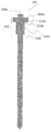
- FIG. 1 is a cross-sectional view showing the structure of a fuel injection valve 100 of the present embodiment.
- FIG. 1 is a longitudinal sectional view of the fuel injection valve 100 and an example of a configuration of an EDU 121 (drive circuit) and an ECU 120 (engine control unit) for driving the fuel injection valve 100.
- EDU 121 drive circuit
- ECU 120 engine control unit
- the fuel injection valve 100 of FIG. 1 is an example of an electromagnetic fuel injection valve for a direct injection gasoline engine in a cylinder, but the effect of the present invention is that the electromagnetic fuel injection valve for a port injection gasoline engine or The present invention is also effective in electromagnetic fuel injection valves for diesel engines.
- ECU 120 and EDU 121 may be configured as an integral part.
- At least a drive circuit of the fuel injection valve 100 is a device that generates a drive voltage of the fuel injection valve 100, and the ECU and the EDU may be integrated, or the EDU may be a single body.
- the ECU 120 takes in signals indicating the state of the engine (internal combustion engine) from various sensors, and calculates an appropriate drive pulse width and injection timing according to the operating conditions of the engine.
- the drive pulse output from the ECU 120 is input to the EDU 121 of the fuel injection valve 100 through the signal line 123.
- the EDU 121 controls the voltage applied to the coil 108 and supplies a current to the coil 108.
- the ECU 120 communicates with the EDU 121 through the communication line 122, and can switch the drive current generated by the EDU 121 according to the pressure of the fuel supplied to the fuel injection valve 100 and the operating condition.
- the EDU 121 can change the control constant through communication with the ECU 120, and the current waveform of the current supplied to the coil 108 changes according to the control constant.
- a metal pipe forming the fuel supply port 112 is attached to a common rail (not shown).
- the common rail is supplied with high pressure fuel from a high pressure fuel pump (not shown) so that high pressure fuel of a set pressure (for example, 35 MPa) can be stored.
- the high-pressure fuel of the common rail is supplied to the inside of the fuel injection valve 100 through the fuel inlet surface 112 a of the fuel supply port 112.
- the fuel injection valve 100 internally includes a valve body 101 that opens and closes a flow path, and a seat member 102 having a conical surface at a position facing the downstream end of the valve body 101 is provided.
- the seat portion 115 for sealing fuel is formed by the seating of the valve body side seat portion 101b of the valve body 101, and the fuel injection hole 116 where the fuel is injected downstream of the seat portion 115 is It is formed.
- the valve body 101 is seated on the seat member 102.
- the valve body 101 is pressed against the seat member 102 by the first spring 110 when the coil 108 is not energized, contacts the seat portion 115 to form a seal seat, and seals the fuel.
- FIG. A sleeve 113 (engagement portion) is attached to the upstream end of the valve body 101.
- the valve body 101 has a sleeve 113.
- the sleeve 113 has a cylindrical portion 1131 attached to the outer diameter side of the small diameter portion of the valve body, and a convex portion 1132 which is convex on the outer diameter side at the upper end of the sleeve 113.
- the biasing force of the first spring 110 is transmitted to the valve body 101 via the convex upper surface 113 a of the sleeve 113, and the valve body 101 is biased in the downstream direction (direction toward the sheet member 102).
- the magnetic circuit is formed by the movable core group 200, the magnetic core 107, the coil 108 located on the outer peripheral side of the magnetic core 107, and the yoke 109 (housing) located on the outer diameter side of the coil
- the valve body 101 is driven by generating an attractive force between the magnetic core 107 and the movable core group 200.
- the movable core group 200 is divided into a first movable core 201 (first mover: outer anchor) and a second movable core 202 (second mover: inner anchor).
- the valve body 101 and the movable core group 200 (the first movable core 201 and the second movable core 202) are contained in the housing portion 111a (housing concave portion) of the nozzle holder 111 (cylindrical member). Further, the valve body 101 opened by the first movable core 201 or the second movable core 202 is configured separately from the first movable core 201 and the second movable core 202 independently.
- the lift amount of the valve body 101 can be changed by changing the value of the current supplied to the coil 108, and the impact force of the valve body 101 on the sheet member 102 is reduced. Can.
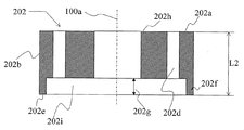
- FIG. 3 and 4 are longitudinal sectional views of the movable core group, and using these, the positional relationship of the movable core group 200 is shown.
- a drive current flows from the EDU 121 (drive circuit) to the coil 108
- a magnetic attraction force is generated between the magnetic core 107 (FIG. 1) and the first movable core 201 and the second movable core 202.
- the first movable core 201 engages with the second movable core 202 via the concave bottom surface 201 e of the first movable core and the lower end surface 202 e of the second movable core 202, and the first movable core 201 faces the magnetic core 107.
- the second movable core 202 is driven toward the magnetic core 107 when moving.
- the sleeve 113 of the valve body 101 engages with the second movable core 202 and is opened by the first movable core 201.
- the coil 108 is not energized, the lower end surface 201 g of the first movable core 201 is in contact with the lower end surface 111 b of the accommodation portion 111 a of the nozzle holder 111, and the movement of the first movable core 201 is restricted.
- the first movable core 201 has a first facing surface 201 a facing the magnetic core 107, and the first facing surface 201 a is attracted to the magnetic core 107.
- the second movable core 202 is configured separately from the first movable core 201, and has a second facing surface 202a facing the magnetic core 107 so that the second facing surface 202a is attracted to the magnetic core 107. It is done.
- a recess 202i is formed on the lower end surface 202e of the second movable core 202.
- the protrusion 202f is formed, and the protrusion 202f contacts the bottom surface of the recess 201c of the first movable core 201 even when the valve is closed, so that a gap 202g is formed between the second movable core 202 and the bottom of the recess 201c. (FIG. 3) is formed.
- the second opposing surface 202 a of the second movable core 202 is disposed on the inner peripheral side with respect to the first opposing surface 201 a of the first movable core 201.
- the inner circumferential portion 201b of the first movable core 201 is configured to face the outer circumferential portion 202b of the second movable core 202 in the direction orthogonal to the axial direction 100a.
- the first movable core 201 has a recess 201c (receiving recess) for receiving the second movable core 202 toward the downstream side on the inner circumferential side, and the second movable core 202 is contained in the recess 201c. There is.
- the concave bottom surface 201e of the first movable core 201 is configured to face the lower end surface 202e of the second movable core 202 in the axial direction 100a (valve body axial direction).
- the axial maximum length L 1 of the first movable core 201 is the same as that of the second movable core 202. It is configured to be longer than the axial maximum length L2. Further, the depth L3 of the recess 201c of the first movable core 201 is also made longer than the axial maximum length L2 of the second movable core 202.
- the valve body 101 has a sleeve lower end surface 113c (valve body engaging portion) which engages with the upstream engagement portion 202h to drive the valve body 101 upstream of the second movable core 202, and When the movable core 202 moves upstream, the valve body 101 is moved upstream (valve opening direction) by the sleeve lower end surface 113c.
- a sleeve lower end surface 113c valve body engaging portion
- the first movable core 201 has a first engagement portion (recessed bottom surface 201 e) engaged with the second movable core 202, and when the first movable core 201 moves in the upstream direction, the first movable core 201 is moved to the first movable core 201.
- the engagement of the engagement portion (recessed bottom surface 201e) and the second engagement portion (lower end surface 202e) of the second movable core 202 moves the second movable core 202 in the upstream direction.
- the upstream engagement portion 202 h engages with the convex lower end surface 113 b of the sleeve 113 to move the valve body 101 to the upstream side.
- the first movable core 201 and the second movable core 202 respectively have a fuel passage hole 201 d and a fuel passage hole 202 d in order to reduce the fluid force generated when moving.
- the area of the fuel passage hole 201d and the hole portion of the fuel passage hole 202d in the vertical direction of the axial direction 100a (valve body axis) is the first movable core 201 (outer diameter side movable core) and the second movable core 202 (inner diameter side movable
- the core has an area sufficient to relieve fluid forces due to the excluded volume when operating.
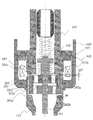
- the nozzle holder 111 has a housing portion 111a for housing the movable core group 200 (movable core group), and as shown in FIG. 5, the bottom surface side (downstream side) of the housing portion 111a.
- the housing lower end surface 111b is provided.
- the first movable core 201 is urged downstream by the urging force of the second spring 103, and the lower end surface 201g of the first movable core 201 and the lower end surface 111b of the housing are in contact with each other. ing.
- FIG. 5 shows a state in which the coil 108 is not energized. Although not illustrated, in this state, the valve body 101 is in a closed state by contacting a valve seat provided on the seat member 102.
- the second spring 103 biases the second movable core 202 away from the lower end surface 113c of the sleeve 113 attached to the valve body 101 (downward).
- the second movable core 202 is biased in the downstream direction by the second spring 103, and the biasing force of the second spring 103 is generated via the lower end surface 202 e of the second movable core 202 and the concave bottom surface 201 e (first concave bottom). It is transmitted to the first movable core 201.
- the first movable core 201 biased to the downstream side is configured such that the lower end surface 201 g of the first movable core 201 and the lower end surface 111 b of the housing portion come in contact with each other. Therefore, the lower end surface 202e of the second movable core 202 and the concave bottom surface 201e (first engaging portion) of the first movable core 201 are in contact with each other, and the second movable core 202 is attached to the valve body 101 It is maintained in a state of being pulled away from the sleeve lower end surface 113c.
- a gap g1 is provided between the second facing surface 202a of the second movable core 202 and the sleeve lower end surface 113c at this time.
- the second movable core 202 (second mover) is disposed in the recess 201 c formed in the first movable core 201 (first mover).
- the second gap (air gap g2 + air gap g3) between the second movable core 202 and the magnetic core 107 Is larger.
- the sum of the magnetic attraction force Fo acting between the first movable core 201 and the magnetic core 107 and the magnetic attraction force Fi acting between the second movable core 202 and the magnetic core 107 is When it becomes larger than the biasing force Fz of the second spring 103, the first movable core 201 and the second movable core 202 are attracted to the magnetic core 107 side, and the movement starts.
- the second movable core 202 (inner diameter side movable core) and the first movable core 201 (only the gap g1 provided in advance between the sleeve lower end surface 113c and the second movable core 202 (inner diameter side movable core)
- the state in which the outer diameter side movable core is displaced is shown.
- the sleeve lower end surface 113c (collision surface) of the sleeve 113 of the valve body 101 and the second opposing surface 202a (upstream end surface) of the second movable core 202 collide with each other.
- kinetic energy stored in the first movable core 201 and the second movable core 202 is used for the valve opening operation of the valve body 101. Therefore, kinetic energy can be used by setting the gap g1 (preliminary lift), and the responsiveness of the valve opening operation can be improved. Therefore, it is possible to open the valve quickly even under high fuel pressure.
- the sum of the magnetic attraction force Fo of the first movable core 201 and the magnetic attraction force Fi of the second movable core 202 in formula (2) is determined by the differential pressure Fp by the fluid acting on the valve body 101 and the first spring 110.
- the condition which becomes larger than the sum of the force Fs and the biasing force ( ⁇ Fz) of the second spring 103 is shown.
- equation (3) shows a condition under which the magnetic attraction force Fi of the second movable core 202 is smaller than the sum of the differential pressure Fp by the fluid acting on the valve body 101 and the biasing force Fs by the first spring 110.
- FIG. 7 corresponds to FIG. 7 and shows a small lift state.
- the first movable core 201 first movable element lifts the valve body 101 by the attraction force of the magnetic core 107 (air gap g2 ').
- the first movable core 201 first movable element
- the first movable core 201 first movable element
- the second movable core 202 second movable element
- the valve body 101 is lifted. More specifically, when the first movable core 201 (first movable element) is attracted to the magnetic core 107, the bottom surface 201 e (bottom surface) of the concave portion 201 c formed in the first movable core 201 is the second movable core 202.
- the second mover is engaged with the lower end surface 202e, and the upstream engagement portion 202h (upper end surface) of the second movable core 202 is the lower end surface 113c (lower end surface) of the sleeve 113 of the valve body 101 By engaging, the valve body 101 is lifted.
- the upstream engagement portion 202h (upper end face) of the second movable core 202 (second mover) is a valve body
- the valve body 101 is lifted by engaging with the sleeve lower end surface 113 c (lower end surface) of the sleeve 113 of 101.
- the first movable core 201 (outer diameter side movable core) is restricted in axial displacement by colliding with the magnetic core 107 or a member that restricts the movement of the first movable core other than the magnetic core 107. Thereby, since the lift amount of the valve body 101 can be stabilized, the stable injection amount can be supplied.
- the second movable core 202 (second movable element) further moves the valve element 101 by the attraction force of the magnetic core 107. Lift (air gap g3).
- the second movable core 202 is configured separately from the valve body 101.
- the displacement of the second movable core 202 is restricted by colliding with the magnetic core 107 or a member that restricts the movement of the second movable core 202. Therefore, the behavior of the valve body 101 is stable, and a stable injection amount can be supplied.
- the magnetic flux starts to disappear from the inner diameter side, and the second movable core 202 (inner diameter side movable core) is the first movable core 201 (outer diameter side) by the differential pressure Fp and the biasing force Fs by the first spring 110. It shifts to the valve closing operation earlier than the movable core).
- the second movable core 202 and the first movable core 201 are separated from the valve body 101. Thereby, the collision energy acting on the valve body 101 and the seat member 102 at the time of valve closing can be reduced by the mass of the second movable core 202 and the first movable core 201. As a result, it is possible to improve the wear resistance of the collision site and to reduce the noise caused by the collision of the valve body 101 with the seat member 102.
- FIG. 10 is a view showing a displacement 501 (lift amount) of the valve body 101, a displacement 502 of the first movable core 201, and a displacement 503 of the second movable core 202 when driving the valve body 101 with a large lift.
- the lower end surface 201 g (downstream end surface) of the first movable core 201 is the lower end surface 111 b of the housing portion of the nozzle holder 111.
- the lower end face 201g of the first movable core 201 (first mover) is It collides with the accommodation section lower end face 111 b (collision receiving section). Thereby, undershooting of the first movable core 201 and the second movable core 202 is suppressed.
- the housing lower end surface 111b (collision receiving portion) is formed by the nozzle holder 111 (cylindrical member) itself. Thereby, the number of parts can be reduced.
- the second movable core 202 moves to the upstream side by the collision energy generated when the first movable core 201 engages with the lower surface 111 b of the housing, the second movable core 202 is biased in the valve closing direction.
- the biasing force of the second spring 103 dampens the motion, and eventually the second movable core 202 engages with the first movable core 201 and becomes stationary.
- the mass ratio of the first movable core 201 and the second movable core 202 is set to the same degree (within 20%), it is possible to quickly damp the motion of the first movable core 201 and the second movable core 202. .
- the time to reach the stationary state of the first movable core 201 is shorter, the error from the injection amount generated when the interval with the next injection is shortened can be reduced, and the injection amount can be stably measured. It becomes.
- the width W of the engagement between the first movable core 201 and the lower end 111b of the housing portion is such that the damper effect by the fluid flowing through the gap of the engaging portion
- the second opposed surface 202a of the second movable core 202 in the valve closed state A gap g1 between the sleeve lower end face 113c, a gap g2 between the first facing surface 201a of the first movable core 201 and the magnetic core 107, a first facing surface 201a of the first movable core 201, and the second movable core 202
- the dimensional relationship of the air gap g3 between the second facing surface 202a and the second facing surface 202a is set to be g2, g3, and g1 in descending order of size.
- the displacement of the valve body 101 can be made variable in two steps. .
- the intake air amount, the internal combustion engine speed, the fuel injection pressure, and the accelerator opening degree are sensed, and the current waveform applied to the fuel injection valve is switched according to the threshold value. It is possible to switch even if the same effect can be obtained by using.
- the first movable core 201 and the lower end surface 111b of the housing portion of the nozzle holder 111 are engaged in the valve closed state as shown in FIG. 5, but as shown in FIG.
- the fixing member 601 may be inserted between the lower end 111b of the housing and the first movable core 201, and the first movable core 201 and the fixing member 601 may be engaged with each other.
- the fixing member 601 collision receiving portion
- the fixing member 601 is attached to the nozzle holder 111 (cylindrical member), and is configured of a member different from the nozzle holder 111. Thereby, only the fixing member 601 can be replaced.
- the magnetic properties of the fixed member 601 are the nozzle holder 111 (cylindrical member) forming the magnetic circuit, the first movable core 201 (first mover), the second movable core 202 (second mover), the magnetic core 107 ( It is preferable to use a material (for example, austenitic stainless steel (nonmagnetic material), martensitic stainless steel, etc.) having a smaller saturation magnetic flux density than that of the fixed core).
- a material for example, austenitic stainless steel (nonmagnetic material), martensitic stainless steel, etc.
- the saturation magnetic flux density of the fixing member 601 (collision receiving portion) is lower than the saturation magnetic flux density of the members constituting the magnetic circuit.
- the magnetic attraction force generated between the first movable core 201 and the fixed member 601 can be reduced, and the reduction of the magnetic attraction force acting between the movable core group 200 and the magnetic core 107 can be suppressed. It becomes.
- the magnetic flux easily flows between the yoke 109 (housing) and the second movable core 202 (second mover) by using the nozzle holder 111 (cylindrical member) as a member (magnetic body) forming a magnetic circuit. Become.
- the magnetic throttling portion 602 is provided on the upstream side (coil 108 side) of the housing lower end surface 111 b to reduce the magnetic flux passing between the first movable core 201 and the nozzle holder 111. It is also possible to suppress the reduction of the magnetic attraction force acting between the magnetic cores 107. Note that the magnetic throttling portion 602 may be provided on the movable core group 200 side or the effect obtained even if provided on the nozzle holder side is not limited and is not limited to this.
- the position of the mover can be quickly stopped at a predetermined position after valve closing while reducing the impact force of the valve body.
- the present invention is not limited to the above-described embodiment, but includes various modifications.
- the embodiments described above are described in detail in order to explain the present invention in an easy-to-understand manner, and are not necessarily limited to those having all the described configurations.
- part of the configuration of one embodiment can be replaced with the configuration of another embodiment, and the configuration of another embodiment can be added to the configuration of one embodiment.
- the embodiment of the present invention may have the following aspects.
- a magnetic core, a first mover (outer anchor) which is attracted to the magnetic core to lift the valve body, and the valve body are separately provided, and the first mover (outer anchor) lifts the valve body
- the second mover (inner anchor) which is attracted by the magnetic core to lift the valve body after colliding with the lift restricting portion, and the first mover after the valve body collides with the valve seat A fuel injection valve comprising: a collision receiving portion with which a downstream surface of the outer anchor collides;
- the fuel injection valve according to (1) further comprising: a cylindrical member (nozzle holder) disposed radially outside the valve body and including the valve body, wherein the collision receiving portion is the cylindrical member (nozzle holder) ) Fuel injection valve formed by itself.
- the fuel injection valve according to (1) further comprising: a cylindrical member (nozzle holder) disposed radially outside the valve body and including the valve body, wherein the collision receiving portion is the cylindrical member (nozzle holder)
- the fuel injection valve which was attached to and was comprised by the said cylindrical member (nozzle holder) and another member.
- the second mover (inner anchor) is disposed in a recess formed in the first mover (outer anchor), and the first mover (closed) is closed when the valve is closed.
- a fuel injection valve arranged such that a second gap between the second mover (inner anchor) and the magnetic core is larger than a first gap between the outer anchor) and the magnetic core.
- a valve body opened by the first mover or the second mover is configured independently of the first mover and the second mover. Fuel injection valve.
- EDU 122 communication line 123: signal line 200: movable core group 201: first movable core 201a: first facing surface 201b: inner circumferential portion 201c: recess 201d: fuel passage hole 201e: recess bottom 201g: lower end surface 202: second Movable core 202a: second facing surface 202b: outer peripheral portion 202d: fuel passage hole 202e: lower end surface 202f: projection 202g: clearance 202h: upstream engagement portion 202i: recess 401: maximum drive current 403: valve body displacement 404: Maximum drive current 406 ... Valve displacement 501 ... Displacement 502 ... Displacement 503 ... Displacement 601 ... Fixing member 602 ... Magnetic throttling portion 1131 ... Cylindrical portion 1132 ... Convex portion
Landscapes
- Engineering & Computer Science (AREA)
- Physics & Mathematics (AREA)
- Electromagnetism (AREA)
- Chemical & Material Sciences (AREA)
- Combustion & Propulsion (AREA)
- Mechanical Engineering (AREA)
- General Engineering & Computer Science (AREA)
- Fuel-Injection Apparatus (AREA)
Abstract
L'invention concerne une soupape d'injection de carburant permettant d'arrêter rapidement la position d'une aiguille à une position prescrite après la fermeture de la soupape, tout en réduisant la force d'impact du corps de soupape. À cet effet, un corps 101 de soupape est pourvu d'un manchon 113. Un premier noyau mobile 201 (première aiguille) amène le corps 101 de soupape à être soulevé par la force d'attraction d'un noyau magnétique 107. Un second noyau mobile 202 (seconde aiguille) amène le corps 101 de soupape à être davantage soulevé par la force d'attraction du noyau magnétique 107 après le soulèvement du corps 101 de soupape provoqué par le premier noyau mobile 201 (première aiguille). Après la mise en appui du corps 101 de soupape sur un élément de siège 102 et la séparation du second noyau mobile 202 (seconde aiguille) du manchon 113, une surface d'extrémité inférieure 201g du premier noyau mobile 201 (première aiguille) entre en collision avec une surface d'extrémité inférieure 111b de partie de réception (partie de réception de collision).
Priority Applications (2)
| Application Number | Priority Date | Filing Date | Title |
|---|---|---|---|
| JP2019548119A JP6782856B2 (ja) | 2017-10-13 | 2018-09-28 | 燃料噴射弁 |
| US16/646,785 US11242830B2 (en) | 2017-10-13 | 2018-09-28 | Fuel injection valve |
Applications Claiming Priority (2)
| Application Number | Priority Date | Filing Date | Title |
|---|---|---|---|
| JP2017-199517 | 2017-10-13 | ||
| JP2017199517 | 2017-10-13 |
Publications (1)
| Publication Number | Publication Date |
|---|---|
| WO2019073816A1 true WO2019073816A1 (fr) | 2019-04-18 |
Family
ID=66100632
Family Applications (1)
| Application Number | Title | Priority Date | Filing Date |
|---|---|---|---|
| PCT/JP2018/036213 Ceased WO2019073816A1 (fr) | 2017-10-13 | 2018-09-28 | Soupape d'injection de carburant |
Country Status (3)
| Country | Link |
|---|---|
| US (1) | US11242830B2 (fr) |
| JP (1) | JP6782856B2 (fr) |
| WO (1) | WO2019073816A1 (fr) |
Citations (5)
| Publication number | Priority date | Publication date | Assignee | Title |
|---|---|---|---|---|
| JP2003511604A (ja) * | 1999-10-07 | 2003-03-25 | ローベルト ボツシユ ゲゼルシヤフト ミツト ベシユレンクテル ハフツング | 燃料噴射弁 |
| JP2013167194A (ja) * | 2012-02-15 | 2013-08-29 | Toyota Motor Corp | 燃料噴射弁 |
| JP2014141924A (ja) * | 2013-01-24 | 2014-08-07 | Hitachi Automotive Systems Ltd | 燃料噴射装置 |
| US20150204289A1 (en) * | 2014-01-17 | 2015-07-23 | Continental Automotive Gmbh | Fuel injection valve for an internal combustion engine |
| JP2015224596A (ja) * | 2014-05-28 | 2015-12-14 | 株式会社デンソー | 燃料噴射弁及びその製造方法 |
Family Cites Families (2)
| Publication number | Priority date | Publication date | Assignee | Title |
|---|---|---|---|---|
| JP4576345B2 (ja) * | 2006-02-17 | 2010-11-04 | 日立オートモティブシステムズ株式会社 | 電磁式燃料噴射弁 |
| JP5981672B2 (ja) | 2016-02-23 | 2016-08-31 | 株式会社日本自動車部品総合研究所 | 燃料噴射弁 |
-
2018
- 2018-09-28 WO PCT/JP2018/036213 patent/WO2019073816A1/fr not_active Ceased
- 2018-09-28 US US16/646,785 patent/US11242830B2/en not_active Expired - Fee Related
- 2018-09-28 JP JP2019548119A patent/JP6782856B2/ja not_active Expired - Fee Related
Patent Citations (5)
| Publication number | Priority date | Publication date | Assignee | Title |
|---|---|---|---|---|
| JP2003511604A (ja) * | 1999-10-07 | 2003-03-25 | ローベルト ボツシユ ゲゼルシヤフト ミツト ベシユレンクテル ハフツング | 燃料噴射弁 |
| JP2013167194A (ja) * | 2012-02-15 | 2013-08-29 | Toyota Motor Corp | 燃料噴射弁 |
| JP2014141924A (ja) * | 2013-01-24 | 2014-08-07 | Hitachi Automotive Systems Ltd | 燃料噴射装置 |
| US20150204289A1 (en) * | 2014-01-17 | 2015-07-23 | Continental Automotive Gmbh | Fuel injection valve for an internal combustion engine |
| JP2015224596A (ja) * | 2014-05-28 | 2015-12-14 | 株式会社デンソー | 燃料噴射弁及びその製造方法 |
Also Published As
| Publication number | Publication date |
|---|---|
| JPWO2019073816A1 (ja) | 2020-09-24 |
| JP6782856B2 (ja) | 2020-11-11 |
| US20200291910A1 (en) | 2020-09-17 |
| US11242830B2 (en) | 2022-02-08 |
Similar Documents
| Publication | Publication Date | Title |
|---|---|---|
| JP6087210B2 (ja) | 燃料噴射弁 | |
| JP5509117B2 (ja) | 燃料噴射装置 | |
| JP6655723B2 (ja) | 燃料噴射弁 | |
| CN107709751B (zh) | 电磁阀 | |
| JP2006017101A (ja) | 燃料噴射弁 | |
| JP2013072298A (ja) | 燃料噴射弁 | |
| CN102828873A (zh) | 喷射阀的阀组件和喷射阀 | |
| CN101506510A (zh) | 燃料喷射阀 | |
| JP2013002332A (ja) | 高圧ポンプおよびその制御方法 | |
| US9890753B2 (en) | High-pressure fuel supply pump | |
| US9995262B2 (en) | Fluid injection valve | |
| JP6613973B2 (ja) | 燃料噴射装置 | |
| JP2013151915A (ja) | 燃料噴射弁 | |
| JP6913816B2 (ja) | 燃料噴射弁及びその組立方法 | |
| JP6782856B2 (ja) | 燃料噴射弁 | |
| US20180195477A1 (en) | Valve for metering a fluid | |
| JP2013064414A (ja) | 燃料噴射弁 | |
| JP2018184854A (ja) | 燃料噴射弁 | |
| JP2006090191A (ja) | 燃料噴射弁 | |
| US20210115887A1 (en) | Fuel injection valve | |
| CN106795843A (zh) | 用于喷射流体的喷射器 | |
| JP2010163981A (ja) | 燃料噴射弁 | |
| JP2017110536A (ja) | 燃料噴射弁 | |
| WO2024190088A1 (fr) | Actionneur électromagnétique et dispositif d'injection de carburant | |
| JP2018105271A (ja) | 燃料噴射弁 |
Legal Events
| Date | Code | Title | Description |
|---|---|---|---|
| 121 | Ep: the epo has been informed by wipo that ep was designated in this application |
Ref document number: 18866428 Country of ref document: EP Kind code of ref document: A1 |
|
| ENP | Entry into the national phase |
Ref document number: 2019548119 Country of ref document: JP Kind code of ref document: A |
|
| NENP | Non-entry into the national phase |
Ref country code: DE |
|
| 122 | Ep: pct application non-entry in european phase |
Ref document number: 18866428 Country of ref document: EP Kind code of ref document: A1 |