WO2019073879A1 - Batterie stratifiée - Google Patents
Batterie stratifiée Download PDFInfo
- Publication number
- WO2019073879A1 WO2019073879A1 PCT/JP2018/037036 JP2018037036W WO2019073879A1 WO 2019073879 A1 WO2019073879 A1 WO 2019073879A1 JP 2018037036 W JP2018037036 W JP 2018037036W WO 2019073879 A1 WO2019073879 A1 WO 2019073879A1
- Authority
- WO
- WIPO (PCT)
- Prior art keywords
- circuit board
- terrace
- laminate
- emboss
- terrace portion
- Prior art date
- Legal status (The legal status is an assumption and is not a legal conclusion. Google has not performed a legal analysis and makes no representation as to the accuracy of the status listed.)
- Ceased
Links
Images





Classifications
-
- H—ELECTRICITY
- H01—ELECTRIC ELEMENTS
- H01M—PROCESSES OR MEANS, e.g. BATTERIES, FOR THE DIRECT CONVERSION OF CHEMICAL ENERGY INTO ELECTRICAL ENERGY
- H01M50/00—Constructional details or processes of manufacture of the non-active parts of electrochemical cells other than fuel cells, e.g. hybrid cells
- H01M50/50—Current conducting connections for cells or batteries
- H01M50/572—Means for preventing undesired use or discharge
- H01M50/574—Devices or arrangements for the interruption of current
-
- H—ELECTRICITY
- H01—ELECTRIC ELEMENTS
- H01M—PROCESSES OR MEANS, e.g. BATTERIES, FOR THE DIRECT CONVERSION OF CHEMICAL ENERGY INTO ELECTRICAL ENERGY
- H01M50/00—Constructional details or processes of manufacture of the non-active parts of electrochemical cells other than fuel cells, e.g. hybrid cells
- H01M50/10—Primary casings; Jackets or wrappings
- H01M50/102—Primary casings; Jackets or wrappings characterised by their shape or physical structure
- H01M50/105—Pouches or flexible bags
-
- Y—GENERAL TAGGING OF NEW TECHNOLOGICAL DEVELOPMENTS; GENERAL TAGGING OF CROSS-SECTIONAL TECHNOLOGIES SPANNING OVER SEVERAL SECTIONS OF THE IPC; TECHNICAL SUBJECTS COVERED BY FORMER USPC CROSS-REFERENCE ART COLLECTIONS [XRACs] AND DIGESTS
- Y02—TECHNOLOGIES OR APPLICATIONS FOR MITIGATION OR ADAPTATION AGAINST CLIMATE CHANGE
- Y02E—REDUCTION OF GREENHOUSE GAS [GHG] EMISSIONS, RELATED TO ENERGY GENERATION, TRANSMISSION OR DISTRIBUTION
- Y02E60/00—Enabling technologies; Technologies with a potential or indirect contribution to GHG emissions mitigation
- Y02E60/10—Energy storage using batteries
Definitions
- the present invention relates to a laminate type battery including a laminate cell in which a power generation element is covered with a laminate sheet and a circuit board.
- a non-aqueous electrolyte battery represented by a lithium ion secondary battery is used as a power source for a portable information terminal, a portable game machine, etc. because of its high energy density.
- a laminate type lithium ion 2 having a substantially rectangular plan view shape in which a thin plate-like power generating element is covered with a flexible laminate sheet.
- Secondary batteries hereinafter referred to as "laminated cells" are often used.
- a circuit board mounted with a protective circuit component (safety circuit component) for protecting the laminate cell from overdischarge and overcharge is integrated with the laminate cell to constitute a laminate type battery.
- the laminate cell has a seal area where a laminate sheet is overlapped and sealed on the outside of the power generation element.
- the sealing area is along three or four sides of the substantially rectangular laminate cell.
- the positive electrode tab and the negative electrode tab connected to the power generation element are led out from one side of the laminate cell.
- the seal area along the side from which the positive electrode tab and the negative electrode tab are led out is called a terrace.
- the circuit board is generally disposed facing the terrace with the surface on which the protective circuit component is mounted facing the terrace (see, for example, Patent Document 1). ).
- the positive electrode tab and the negative electrode tab led out from the terrace portion or another tab connecting these and the circuit substrate are bent. That is, in the process of manufacturing the laminate type battery, it is necessary to press the circuit board against the terrace portion against the elastic repulsive force of the tab. At this time, when an excessive pressing force is applied to the circuit board, the protective circuit component mounted on the circuit board or the circuit board collides with the terrace portion or another electronic component (for example, a breaker) provided in the terrace portion. As a result, electronic components such as a circuit board and a protective circuit component existing between the circuit board and the terrace portion may be damaged or a laminate sheet constituting the terrace portion may be damaged.
- the object of the present invention is to solve the problems of the above-mentioned conventional laminate-type battery, and to miniaturize the laminate-type battery capable of preventing damage to electronic components such as circuit boards and protective circuit parts and laminate sheets. It is to provide.
- the laminate type battery of the present invention comprises a laminate cell having a substantially rectangular shape in plan view, in which a power generation element is covered with a flexible laminate sheet, and a circuit board on which a protective circuit component is mounted.
- the laminate cell comprises a sealing area in which the laminate sheets are stacked and sealed.
- the seal area includes a positive electrode tab connected to the power generation element and a terrace along the side from which the negative electrode tab is derived.
- the circuit board is disposed to face the terrace with the surface on which the protective circuit component is mounted facing the terrace.
- a compressively deformable cushioning material is provided between the circuit board and the terrace portion.
- the cushioning material suppresses the movement of the circuit board toward the terrace portion. For this reason, it is possible to prevent the circuit board, the electronic components present between the circuit board and the terrace portion, and the laminate sheet constituting the terrace portion from being damaged.
- the laminate type battery can be miniaturized.
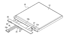
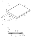
- FIG. 1 is an exploded perspective view of a laminate type battery according to Embodiment 1 of the present invention.
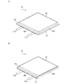
- FIG. 2A is a perspective view of a laminate cell constituting the laminate type battery in accordance with Embodiment 1 of the present invention.
- FIG. 2B is a perspective view showing the laminated cell of FIG. 2A in a state where seal areas along two opposing sides are bent.
- FIG. 3 is a perspective view showing one process of manufacturing the laminate type battery in accordance with Embodiment 1 of the present invention.
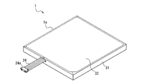
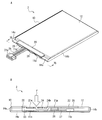
- FIG. 4A is a perspective view of a laminate type battery in accordance with Embodiment 1 of the present invention.
- FIG. 4B is an arrow sectional view of the laminate type battery taken along a plane including line 4B-4B of FIG. 4A.
- FIG. 5 is a perspective view of a laminate-type battery according to Embodiment 1 of the present invention covered with an exterior sheet.
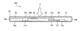
- FIG. 6 is a cross-sectional view of a laminate-type battery according to a comparative example.
- FIG. 7A is a perspective view of a laminate type battery in accordance with Embodiment 2 of the present invention.
- FIG. 7B is an arrow sectional view of the laminate type battery taken along a plane including line 7B-7B of FIG. 7A.
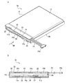
- FIG. 8A is a perspective view of a laminate type battery in accordance with Embodiment 3 of the present invention.
- FIG. 8B is a side view of the laminated battery as viewed along arrow 8B of FIG. 8A.
- FIG. 9A is a perspective view of another laminate-type battery according to Embodiment 3 of the present invention.
- FIG. 9B is a side view of the laminated battery as viewed along arrow 9B of FIG. 9A.
- FIG. 10A is a perspective view of a laminate cell constituting a laminate type battery according to Embodiments 4 and 5 of the present invention.
- FIG. 10B is a side view of a laminate cell according to Embodiments 4 and 5 of the present invention as viewed along arrow 10B of FIG. 10A.
- FIG. 11A is a perspective view showing a state in which seal areas (ear parts) along two opposing sides of a laminate cell constituting a laminate type battery according to a fourth embodiment of the present invention are bent.
- FIG. 11B is a side view of a laminate cell according to Embodiment 4 of the present invention as viewed along arrow 11B of FIG. 11A.
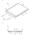
- FIG. 12A is a perspective view of a laminate type battery in accordance with Embodiment 4 of the present invention.
- FIG. 12B is a side view of the laminated battery as viewed along arrow 12B of FIG. 12A.
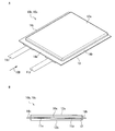
- FIG. 13A is a perspective view showing a state in which seal areas (ear parts) along two opposing sides of a laminate cell constituting a laminate type battery according to a fifth embodiment of the present invention are bent.
- 13B is a side view of a laminate cell according to Embodiment 5 of the present invention, viewed along arrow 13B in FIG. 13A.
- FIG. 14A is a perspective view of a laminate type battery in accordance with Embodiment 5 of the present invention.
- FIG. 14B is a side view of the laminated battery as viewed along arrow 14B of FIG. 14A.
- a double-sided adhesive tape or an adhesive may be applied to both sides of the cushion material so that the circuit board and the terrace portion are connected via the cushion material.
- a breaker that shuts off the current at the time of abnormal overheating may be provided on the surface of the terrace portion facing the circuit board, or on the surface of the circuit board on which the protective circuit component is mounted.
- the cushioning material may be arranged not to face the breaker.
- the cushion material may be compressed and deformed in a direction in which the circuit board and the terrace portion face each other. In this aspect, even if the distance between the circuit board and the terrace portion is narrow, the circuit board, the electronic components existing between the circuit board and the terrace portion, and the laminate sheet constituting the terrace portion are damaged. It can be reliably prevented.
- the above-mentioned laminate type battery of the present invention may further include external wiring connected to the surface of the circuit board facing the terrace portion.
- the external wiring may be led out parallel to the longitudinal direction of the terrace portion.
- the cushion material may be disposed to press the external wiring toward the circuit board.
- Such an aspect is advantageous for preventing external wiring from colliding with a seal portion (ear portion) extending perpendicularly to the terrace portion.
- the laminate cell may be provided with an emboss that protrudes to one side with respect to the terrace portion corresponding to the power generation element.
- the seal area may include a first ear and a second ear connected to both ends of the terrace and along a direction perpendicular to the side along which the terrace extends.
- the first ear portion and the second ear portion may be bent at substantially right angles to the same side as the emboss.
- the circuit board may be disposed on the same side as the side on which the emboss of the terrace portion protrudes. According to this aspect, it is possible to configure the laminate type battery of the present invention using the single embossed type laminate cell.
- the laminate cell has a first emboss that protrudes to one side with respect to the terrace portion corresponding to the power generation element, and protrudes to the other side with respect to the terrace portion corresponding to the power generation element
- a second emboss may be provided.
- the seal area may include a first ear and a second ear connected to both ends of the terrace and along a direction perpendicular to the side along which the terrace extends.
- the first ear portion may be bent at substantially a right angle on the same side as the first emboss or the second emboss.
- the second ear portion may be bent at substantially a right angle on the same side as the first emboss or the second emboss.
- the circuit board may be disposed on the same side as the side where the first emboss of the terrace portion protrudes. According to this aspect, it is possible to configure the laminate type battery of the present invention using the dual embossing type laminate cell.
- FIG. 1 is an exploded perspective view of a laminate type battery (hereinafter simply referred to as “battery”) 1 according to Embodiment 1 of the present invention.
- the battery 1 includes a laminate cell (hereinafter simply referred to as "cell") 10, a circuit board 20, and a breaker 27.
- FIG. 2A is a perspective view of the cell 10.
- the cell 10 has a substantially rectangular planar view shape, and has a thin plate shape having a thickness smaller than the vertical and horizontal dimensions of the substantially rectangular shape.
- a thin plate-like power generating element (not shown) having a substantially rectangular shape in a plan view is sealed together with an electrolytic solution in an outer package made of a laminate sheet 13.
- the power generation element is a positive electrode in which a positive electrode mixture layer containing a positive electrode active material is coated on both sides of a predetermined region of a positive electrode current collector, and a negative electrode mixture layer containing negative electrode active materials on both sides of a predetermined region of the negative electrode collector.
- coating formation was carried out are an electrode laminated body formed by laminating
- the type of battery is not particularly limited, but a secondary battery, preferably a lithium ion secondary battery is preferable.
- the laminate sheet 13 is thinner and more flexible than the power generation element.
- the laminate sheet 13 is, for example, a flexible multilayer sheet in which a heat fusible resin layer (for example, a modified polyolefin layer) is laminated on the side of the base layer made of aluminum or the like facing the power generation element. Good.
- a heat fusible resin layer for example, a modified polyolefin layer
- One rectangular laminate sheet 13 is folded in two so as to sandwich the power generation element, and is laminated outside the power generation element and sealed by a heat sealing method or the like.
- the seal regions 14a, 14b and 14c in which the laminate sheet 13 is sealed are along three sides of the substantially rectangular cell 10.
- the seal areas 14a, 14b and 14c are along a common common plane.
- the cell in which the emboss 12 is projected on only one side with respect to the seal areas 14a, 14b and 14c is generally referred to as a “one-emboss type” or the molded shape of the laminate sheet 13. It is called one-stop type.
- the side from which the emboss 12 is projected is referred to as the "front” of the cell 10 and the opposite side is referred to as the "rear” of the cell 10. Call it Moreover, the direction which ties the front and back is called “thickness direction”. The direction parallel to the plane common to the seal areas 14a, 14b, 14c is called “horizontal direction”.
- the positive electrode tab 11p and the negative electrode tab 11n are derived from the seal region 14a.
- the positive electrode tab 11p and the negative electrode tab 11n have a strip shape, and extend in a direction perpendicular to the longitudinal direction of the seal area 14a (that is, in a direction parallel to the pair of seal areas 14b and 14c connected to both ends of the seal area 14a). It extends along.
- the positive electrode tab 11 p is made of, for example, a thin plate of aluminum, and is electrically connected to a plurality of positive electrode current collectors (not shown) constituting the power generation element.
- the negative electrode tab 11 n is made of, for example, a thin plate of nickel and is electrically connected to a plurality of negative electrode current collectors (not shown) constituting the power generation element.
- the seal area 14 a from which the positive electrode tab 11 p and the negative electrode tab 11 n are derived is referred to as a “terrace portion”.
- regions 14b and 14c connected to the both ends of the terrace part 14a are called "ear part.”
- the ears 14 b and 14 c extend along a side perpendicular to the side of the cell 10 along the terrace 14 a. In order to reduce the external dimensions of the cell 10, as shown in FIG. 2B, the ear portions 14b and 14c are bent substantially at right angles to the terrace portion 14a on the side of the emboss 12.
- the folded ear portions 14 b and 14 c are fixed to the side surface of the emboss 12 using a double-sided adhesive tape or the like.
- the terrace portion 14a is surrounded in three directions by the emboss 12 and the ear portions 14b and 14c.
- the circuit board 20 is an elongated thin plate and has substantially the same longitudinal dimension as the terrace portion 14a.
- a protective circuit component (safety circuit component) 22 composed of an electronic component such as a FET element is mounted, and a charging circuit may be optionally formed.
- two protection circuit components 22 are mounted, but the number of protection circuit components 22 is not limited to this and is arbitrary.
- a positive electrode input terminal 21p and a negative electrode input terminal 21n are provided on the lower surface of the circuit board 20 .
- the external wiring 24 is connected to a terminal (not shown in FIG.
- the external wiring 24 is composed of a plurality of (five in the first embodiment) cables having flexibility.
- the type of the plurality of cables is not particularly limited, but may include, for example, a positive electrode cable, a negative electrode cable, a temperature detection cable for detecting the temperature of the laminate cell 10, and the like.
- the number of cables constituting the external wiring 24 and the function of each cable are not limited to the present embodiment and can be arbitrarily changed.
- the breaker 27 is provided with a thin plate-like element main body that functions as a current interrupting device that shuts off current when abnormal overheating occurs.
- the first lead 27a and the second lead 27b are derived from the element body in the directions opposite to each other.
- the first lead 27a and the second lead 27b are strip-like thin plates made of a conductive metal.
- the positive electrode tab 11 p of the cell 10 is connected to the first lead 27 a.
- the second lead 27 b is connected to the positive electrode input terminal 21 p provided on the lower surface of the circuit board 20 via the conductive tab 28.
- the conductive tab 28 is a strip-like thin plate made of a conductive metal (for example, nickel).
- the negative electrode tab 11 n of the cell 10 is connected to the negative electrode input terminal 21 n provided on the lower surface of the circuit board 20.
- the cushioning material 25 is attached to the lower surface of the circuit board 20.
- the cushion material 25 has a substantially rectangular parallelepiped shape and is made of a compressively deformable elastic body.
- the cushion material 25 is not limited, but may be a material such as a foam material or a sponge, which is easily deformed when an external force is applied and restored to its initial shape when the external force is removed.
- the cushioning material 25 preferably has insulating properties.
- the cushion material 25 may be, for example, a urethane foam or a polyethylene sponge, and as an example, "PORON (registered trade)" manufactured by Roger Suinoac Co., Ltd. can be exemplified.
- the positive electrode tab 11 p is bent into a substantially “U” shape, and the breaker 27 is overlapped on the same side as the side of the terrace portion 14 a from which the emboss 12 protrudes.
- the method of fixing the breaker 27 to the terrace portion 14a is not limited, for example, a double-sided adhesive tape or an adhesive can be used.
- a negative tab 11 n and a conductive tab 28 extend parallel to each other between the cell 10 and the circuit board 20.
- a cushion material 25 is attached to the lower surface of the circuit board 20.
- the circuit board 20 is made to face the terrace 14a such that the surface of the circuit board 20 on which the protective circuit component 22 is mounted faces the terrace 14a.
- the negative electrode tab 11 n and the conductive tab 28 are bent in two directions in opposite directions so as to form a substantially “Z” shape when viewed along the longitudinal direction of the terrace portion 14 a.
- FIG. 4A is a perspective view of the battery 1 in which the circuit board 20 is superimposed on the terrace portion 14a.
- the outer surface (the surface opposite to the surface on which the protective circuit component 22 is mounted) of the circuit board 20 is at substantially the same height as the top surface of the emboss 12 of the cell 10.
- the battery main body 1a including the cell 10 and the circuit board 20 is covered with exterior sheets 31, 32 (see FIG. 1) as needed (see FIG. 5).
- the exterior sheets 31 and 32 are made of, for example, resin or paper having insulation properties, but not limited thereto.
- FIG. 4B is a cross-sectional view of the battery 1 along the plane including the line 4B-4B in FIG. 4A (the plane across the external wiring 24).
- the circuit board 20 and the terrace portion 14a are separated and opposed in the thickness direction.
- a protective circuit component 22 and a sealing portion 24 b are provided on the surface of the circuit board 20 facing the terrace portion 14 a.
- the sealing portion 24 b is made of a known glue, an insulating resin or an adhesive, and seals and insulates an electrical connection portion between the external wiring 24 and the circuit board 20.
- a breaker 27 is provided on the surface of the terrace portion 14 a facing the circuit board 20.
- the negative electrode tab 11 n and the conductive tab 28 are bent between the circuit board 20 and the terrace portion 14 a.
- the cushion material 25 is interposed between the circuit board 20 and the terrace portion 14a. More specifically, the cushion material 25 is located between the protective circuit component 22 provided on the circuit board 20 and the sealing portion 24 b and the terrace portion 14 a. A double-sided adhesive tape or an adhesive is applied to the upper and lower surfaces of the cushion material 25. For this reason, the circuit board 20 and the terrace portion 14 a are connected via the cushion material 25. The cushion material 25 is located between the negative electrode tab 11 n and the conductive tab 28 in the longitudinal direction of the circuit board 20.
- FIG. 6 is a cross-sectional view of a laminate type battery 101 according to a comparative example, similarly to FIG. 4B.
- the comparative example of FIG. 6 differs from the first embodiment of FIG. 4B only in that the cushion material 25 is not provided.
- the circuit board 20 moves toward the terrace portion 14a more than necessary, and the circuit board 20 and mounted components mounted on the circuit board 20 (protective circuit component 22, sealing portion 24b, etc.) Collide with the breaker 27 provided on the terrace portion 14a and the laminate sheet constituting the terrace portion 14a.
- the circuit board 20, the mounted components, and the breaker 27 may be damaged (for example, cracking or cracking), or the laminate sheet constituting the terrace portion 14a may be damaged. Damage to the laminate sheet can cause electrolyte leakage due to the laminate sheet breakage, moisture penetration into the cell 10, and short circuit in the cell 10.
- the excessive force F may be applied not only when bending the negative electrode tab 11 n and the conductive tab 28 but also when handling the battery 101 in the subsequent manufacturing process of the battery 101.
- the cushion material 25 is provided between the circuit board 20 and the terrace portion 14a.
- the cushion material 25 opposes the force F, so that the circuit board 20 is prevented from moving more than necessary toward the terrace portion 14a.
- the circuit board 20 and mounted components (such as the protective circuit component 22 and the sealing portion 24b) do not collide with the breaker 27 provided in the terrace portion 14a or the laminate sheet constituting the terrace portion 14a. Therefore, it is prevented that the circuit board 20, the mounted parts existing between the circuit board 20 and the terrace portion 14a, and the electronic components such as the breaker 27 are damaged or the laminate sheet constituting the terrace portion 14a is damaged. can do.
- the double-sided adhesive tape or adhesive is applied to the upper and lower surfaces of the cushioning material 25. Therefore, once the circuit board 20 is superimposed on the terrace portion 14a via the cushioning material 25 as shown in FIG. Circuit board 20 and terrace part 14a are connected via each other.
- the cushioning material 25 opposes the elastic repulsive force of the negative electrode tab 11 n and the conductive tab 28 which tends to separate the circuit board 20 from the terrace portion 14 a, and prevents the circuit board 20 from separating from the terrace portion 14 a. Therefore, the handleability of the battery 1 in the subsequent manufacturing process of the battery 1 (for example, the attachment of the exterior sheets 31 and 32) is improved, and the manufacturing of the battery 1 becomes easy.
- the circuit board 20 is disposed to face the terrace portion 14a between the ear portions 14b and 14c bent along the thickness direction. For this reason, the circuit board 20 is prevented from protruding largely from the cell 10 in the horizontal direction.
- the battery 1 of the first embodiment is miniaturized and excellent in volumetric energy density.
- the cushion material 25 is disposed so as not to face the breaker 27. For this reason, even if the excessive force F is applied, the cushion material 25, the circuit board 20, and the mounted components of the circuit board 20 do not contact the breaker 27. Since the external force can be prevented from being applied to the breaker 27, the reliability of the operation of the breaker 27 is improved.
- FIG. 7A is a perspective view of a laminate type battery 2 according to Embodiment 2 of the present invention.
- FIG. 7B is an arrow sectional view of battery 2 along a plane including line 7B-7B of FIG. 7A.
- the second embodiment is different from the first embodiment in the arrangement of various members disposed between the circuit board 20 and the terrace portion 14a.
- the protection circuit component 22 mounted on the circuit board 20 and the breaker 27 superimposed on the terrace portion 14 a face each other in the thickness direction.
- the emboss 12 is thinner, and the distance between the circuit board 20 and the terrace portion 14a is narrow so as to correspond thereto. Therefore, even if the circuit board 20 is slightly moved toward the terrace portion 14 a by the application of the force F, the protective circuit component 22 is likely to collide with the breaker 27.
- the cushioning material 25 having a larger thickness in the natural state than the gap between the circuit board 20 and the terrace portion 14a is used.
- the cushion material 25 is thick It is greatly compressed and deformed in the longitudinal direction. Since the repulsive force in the thickness direction of the cushioning material 25 is large, it is possible to oppose a larger force F.
- the circuit board 20 and the mounted parts do not collide with the breaker 27 provided in the terrace portion 14a or the laminate sheet constituting the terrace portion 14a. Therefore, it is ensured that the circuit board 20, the mounted parts existing between the circuit board 20 and the terrace portion 14a, and the electronic components such as the breaker 27 are damaged or the laminate sheet constituting the terrace portion 14a is damaged. Can be prevented.
- the cushion material 25 is disposed so as not to face the breaker 27. For this reason, the cushion material 25 that has been compressed and deformed does not apply an external force to the breaker 27. This is advantageous for improving the reliability of the operation of the breaker 27.
- the longitudinal dimension of the circuit board 20 is shorter than the longitudinal dimension of the terrace portion 14 a.
- the cushioning material 25 is bent to arrange the cushioning material 25 in a limited area where the circuit board 20 and the terrace portion 14a are opposed so as to be able to oppose the force F. It is arrange
- the cushion material 25 may be disposed at a position not in contact with the tabs 11 p and 11 n.
- the dimension in the longitudinal direction of the circuit board 20 is arbitrary.
- the circuit board 20 is set so as not to protrude in the horizontal direction from the ear portions 14 b and 14 c.
- the second embodiment is the same as the first embodiment except for the above.
- the description of the first embodiment is appropriately applied to the second embodiment.
- FIG. 8A is a perspective view of a laminate type battery 3 according to Embodiment 3 of the present invention.
- FIG. 8B is a side view of battery 3 as viewed along arrow 8B of FIG. 8A.
- the external wiring 24 is an end of one side (the first ear portion 14b side) of the circuit board 20 in the shape of an elongated rectangle in plan view. It is connected to the vicinity and is drawn out parallel to the longitudinal direction of the circuit board 20 (or the terrace portion 14a) from the side of the first ear portion 14b.
- the external wiring 24 is connected to the circuit board 20 at a sealing portion 24b provided on the surface of the circuit board 20 facing the terrace portion 14a. ing.
- the emboss 12 is relatively thick, the bent ear portion 14 b and the circuit board 20 are separated in the thickness direction. For this reason, the external wiring 24 can be led out from the circuit board 20 along the horizontal direction beyond the ears 14 b without colliding with the ears 14 b.
- Cushioning members 25a and 25b are provided between the circuit board 20 and the terrace portion 14a. For this reason, as in the first embodiment, even if a force directed to the terrace portion 14a is applied to the circuit board 20, the circuit board 20 and mounted components (such as the protective circuit component 22 and the sealing portion 24b) are the terrace portion 14a. It does not collide with the laminated sheet which comprises the breaker 27 and the terrace part 14a which were provided. Therefore, it is prevented that the circuit board 20, the mounted parts existing between the circuit board 20 and the terrace portion 14a, and the electronic components such as the breaker 27 are damaged or the laminate sheet constituting the terrace portion 14a is damaged. can do.
- two cushion members 25 a and 25 b are provided between the circuit board 20 and the terrace portion 14 a.
- the first cushioning material 25a is disposed in the vicinity of the second ear 14c, and the second cushioning material 25b is provided in the vicinity of the first ear 14b.
- the second cushion material 25 b presses the external wiring 24 against the circuit board 20 so that the external wiring 24 does not hang down to the terrace portion 14 a side. Therefore, the external wiring 24 is prevented from hanging down and colliding with the upper end of the ear portion 14b.
- the ear portion 14b may be deformed, and the laminate sheet constituting the ear portion 14b may be damaged. Damage to the laminate sheet can lead to electrolyte leakage due to laminate sheet breakage and short circuits in the cell 10.
- the second cushion material 25 b is advantageous for preventing such a situation from occurring.
- the cushioning members 25 a and 25 b are disposed so as not to face the breaker 27. For this reason, the cushion members 25 a and 25 b that are compressed and deformed do not apply an external force to the breaker 27. This is advantageous for improving the reliability of the operation of the breaker 27.
- one of the two cushion members 25a and 25b may be omitted.
- FIG. 9A is a perspective view of another laminate type battery 3a according to Embodiment 3 of the present invention.
- FIG. 9B is a side view of battery 3a taken along arrow 9B of FIG. 9A.
- the battery 3a is shown in FIGS. 8A and 8B in that a single cushion material 25 is disposed between the circuit board 20 and the terrace portion 14a over substantially the entire area of the circuit board 20 in the longitudinal direction. Different from battery 3. Since the cushion material 25 is disposed over substantially the entire area where the circuit board 20 and the terrace portion 14a face each other, the circuit board 20 and mounting components can be mounted even if the circuit board 20 is subjected to a force directed to the terrace portion 14a.
- the protective circuit component 22, the sealing portion 24b, and the like do not collide with the breaker 27 provided in the terrace portion 14a or the laminate sheet constituting the terrace portion 14a. Therefore, it is more likely that the circuit board 20, the mounted parts existing between the circuit board 20 and the terrace portion 14a, and the electronic components such as the breaker 27 may be damaged or the laminate sheet constituting the terrace portion 14a may be damaged. It can be reliably prevented.
- the cushioning material 25 is also disposed on the breaker 27. However, since the cushioning material 25 is opposed to the terrace portion 14a over a wide area, the external force that the breaker 27 receives from the cushioning material 25 is relatively small.
- the configuration in which the cushion material 25 is disposed over substantially the entire area where the circuit board 20 and the terrace portion 14a face each other as in the battery 3a may be applied to the first and second embodiments.
- the third embodiment is the same as the first embodiment except for the above.
- the description of the first embodiment is appropriately applied to the third embodiment.
- FIG. 10A is a perspective view of a laminate cell (hereinafter simply referred to as “cell”) 10 b constituting a laminate type battery 4 (see FIGS. 12A and 12B described later) according to Embodiment 4 of the present invention.
- FIG. 10B is a side view of cell 10b as viewed along arrow 10B of FIG. 10A.
- substantially rectangular embossments 12a and 12b corresponding to the power generation element protrude on both sides in the thickness direction with respect to the seal regions 14a, 14b and 14c.
- the protruding height of the first emboss 12a protruding to one side with respect to the sealing regions 14a, 14b and 14c may be the same as or different from the protruding height of the second emboss 12b protruding to the other side. It may be As in the case of the cell 10b, the cells in which the emboss 12a and 12b are projected on both sides with respect to the seal regions 14a, 14b and 14c are generally referred to It is called an aperture type.
- the direction connecting the first emboss 12a and the second emboss 12b is referred to as the "thickness direction" or the "height direction".
- the ear portions 14b and 14c are substantially flush with the terrace portion 14a on the same side as the first emboss 12a. It is bent at a right angle.
- the folded ear portions 14 b and 14 c are fixed to the side surface of the first emboss 12 a using a double-sided adhesive tape or the like.
- the terrace portion 14a is surrounded in three directions by the first emboss 12a and the ear portions 14b and 14c.
- FIG. 12A is a perspective view of a laminate type battery (hereinafter simply referred to as “battery”) 4 as viewed from the first embossed portion 12 a side.
- FIG. 12B is a side view of battery 4 taken along arrow 12B of FIG. 12A.
- the breaker 27 is provided on the same side of the terrace portion 14 a as the side from which the first emboss 12 a protrudes.
- the circuit board 20 faces the surface of the terrace portion 14 a on the same side as the side from which the first emboss 12 a protrudes.
- the external wiring 24 is connected in the vicinity of one end of the circuit board 20 in the longitudinal direction (the side of the first ear 14b), and from the side of the first ear 14b, the external wiring 24 is connected to the terrace 14a (or the circuit board 20). It is derived parallel to the longitudinal direction.
- the battery 4 of the fourth embodiment is the battery 3 of the third embodiment (FIG. 8A, FIG. 8B, except that the double-embossed cell 10b is used in which the ear portions 14b and 14c are bent to the same side as the first emboss 12a. See 8B).
- the description of the third embodiment is appropriately applied to the fourth embodiment.
- the ear portions 14b and 14c may be bent substantially at right angles to the terrace portion 14a on the same side as the second emboss 12b.
- the circuit board 20 and the breaker 27 are disposed on the side of the first embossed portion 12a with respect to the terrace portion 14a, as in FIGS. 12A and 12B. Since the ear portion 14 b and the external wiring 24 are disposed on the opposite side to each other with respect to the terrace portion 14 a, a collision between the external wiring 24 and the ear portion 14 b can be avoided. As a result, the possibility of damage to the ear portion 14b due to the collision of the external wiring 24 or a short circuit between the external wiring 24 and the ear portion 14b is reduced. This is advantageous for improving the safety of the battery.
- the both embossed type cells 10b shown in the fourth embodiment may be applied to the batteries 1 and 2 of the first and second embodiments.
- FIG. 13A is a perspective view of a laminate cell (hereinafter simply referred to as “cell”) 10c that constitutes a laminate type battery 5 (see FIGS. 14A and 14B described later) according to Embodiment 5 of the present invention.
- FIG. 13B is a side view of cell 10c taken along arrow 13B of FIG. 13A.
- the cell 10c is a double-embossed cell (see FIGS. 10A and 10B) as in the cell 10b of the fourth embodiment.
- the first ear portion 14 b is bent substantially at right angles to the terrace portion 14 a on the same side as the second emboss 12 b
- the second ear portion 14 c is the first It is bent substantially at right angles to the terrace portion 14a on the same side as the emboss 12a.
- the folded first and second ear portions 14b and 14c are respectively fixed to the side surfaces of the second and first embossments 12b and 12a using a double-sided adhesive tape or the like.
- the terrace 14a is surrounded in two directions by the first emboss 12a and the second ear 14c, and is surrounded in the two directions by the second emboss 12b and the first ear 14b.
- FIG. 14A is a perspective view of a laminate type battery (hereinafter simply referred to as “battery”) 5 as viewed from the first embossed portion 12 a side.
- FIG. 14B is a side view of battery 5 taken along arrow 14B of FIG. 14A.
- the breaker 27 is provided on the same side of the terrace portion 14 a as the side from which the first emboss 12 a protrudes.
- the circuit board 20 faces the surface of the terrace portion 14 a on the same side as the side from which the first emboss 12 a protrudes.
- the external wiring 24 is connected in the vicinity of one end of the circuit board 20 in the longitudinal direction (the side of the first ear 14b), and from the side of the first ear 14b, the external wiring 24 is connected to the terrace 14a (or the circuit board 20). It is derived parallel to the longitudinal direction.
- the first ear portion 14b and the external wiring 24 are both disposed on the same side with respect to the terrace portion 14a. For this reason, the external wiring 24 may collide with the first ear portion 14 b.
- the height of the protrusion of the first emboss 12a from the terrace portion 14a is often low, so the circuit board 20 is higher than the top surface of the first emboss 12a.
- the first ear portion 14 b and the external wire 24 are disposed on the opposite side to the terrace portion 14 a, collision between the external wire 24 and the first ear portion 14 b should be avoided. Can. As a result, the possibility of damage to the first ear portion 14b due to the collision of the external wiring 24 or a short circuit between the external wiring 24 and the first ear portion 14b is reduced. This is advantageous for improving the safety of the battery 5.
- the fifth embodiment is the same as the fourth embodiment except for the above.
- the description of the fourth embodiment is appropriately applied to the fifth embodiment.
- the both embossing type cells 10c shown in the fifth embodiment may be applied to the batteries 1 and 2 of the first and second embodiments.
- the arrangement of the mounted components (the protective circuit component 22 and the sealing portion 24b) on the circuit board 20, the positive electrode input terminal 21p, the negative electrode input terminal 21n, and the like can be arbitrarily changed.
- the number of protective circuit components 22 is also not limited. Other components may be provided on the circuit board 20.
- connection paths between the positive electrode tab 11p and the negative electrode tab 11n of the cells 10, 10a, 10b and the circuit board 20 are not limited to the above-described first to fifth embodiments.
- the positive electrode tab 11p and the first lead 27a of the breaker 27 may be connected via another conductive tab.
- the breaker 27 may be provided between the negative electrode tab 11 n and the negative electrode input terminal 21 n.
- the breaker 27 does not have to be provided on the terrace portion 14a.
- the breaker 27 may be provided on the surface of the circuit board 20 on which the protective circuit component 22 is mounted.
- the cushioning members 25, 25 a, 25 b may be disposed between the circuit board 20 and the terrace portion 14 a.
- the position, the number, the size, and the like of the cushion members 25, 25a, 25b can be set arbitrarily.
- the external wiring 24 may be led out along the longitudinal direction of the terrace portion 14a from the side of the second ear portion 14c instead of the first ear portion 14b.
- the external wiring 24 can also be led out along the longitudinal direction of the terrace portion 14a from the side of the second ear portion 14c instead of the first ear portion 14b.
- the first ear portion 14b is bent substantially at right angles to the terrace portion 14a on the same side as the first emboss 12a
- the second ear portion 14c is on the same side as the second emboss 12b with respect to the terrace portion 14a.
- they are bent substantially at right angles. That is, it is preferable that the ear portion (14a or 14b) on the side from which the external wiring 24 is led out is bent substantially at a right angle to the side opposite to the external wiring 24 with respect to the terrace portion 14a.
- the field of application of the present invention can be widely used as a battery incorporated in a portable electronic device requiring high volume energy density, but not limited thereto.
- it can be preferably used as a small-sized, large-capacity battery built in an electronic device such as a mobile phone, a smartphone, a tablet terminal, a notebook computer, an electronic dictionary, an electronic book, a portable game machine and the like.
Landscapes
- Chemical & Material Sciences (AREA)
- Chemical Kinetics & Catalysis (AREA)
- Electrochemistry (AREA)
- General Chemical & Material Sciences (AREA)
- Battery Mounting, Suspending (AREA)
- Connection Of Batteries Or Terminals (AREA)
Abstract
L'invention concerne une batterie (1) stratifiée qui comporte : une pile stratifiée (10) qui est obtenue en conditionnant un élément de génération de puissance électrique dans une feuille (13) stratifiée, et qui a une forme généralement rectangulaire en vue planaire; et une carte de circuit imprimé (20) sur laquelle est monté un composant de circuit de protection (22). La pile stratifiée (10) inclut une partie en terrasse (14a) où la feuille (13) stratifiée est recouverte. La carte de circuit imprimé (20) est disposée de manière à faire face à la partie en terrasse (14a), la surface sur laquelle est monté le composant de circuit de protection (22) étant montée de manière à faire face à la partie en terrasse (14a). Un matériau d'amortissement (25) qui est déformable par compression est disposé entre la carte de circuit imprimé (20) et la partie en terrasse (14a).
Priority Applications (1)
| Application Number | Priority Date | Filing Date | Title |
|---|---|---|---|
| CN201880056040.4A CN111052438B (zh) | 2017-10-12 | 2018-10-03 | 层叠型电池 |
Applications Claiming Priority (4)
| Application Number | Priority Date | Filing Date | Title |
|---|---|---|---|
| JP2017198735 | 2017-10-12 | ||
| JP2017-198735 | 2017-10-12 | ||
| JP2018019051A JP7033459B2 (ja) | 2017-10-12 | 2018-02-06 | ラミネート型電池 |
| JP2018-019051 | 2018-02-06 |
Publications (1)
| Publication Number | Publication Date |
|---|---|
| WO2019073879A1 true WO2019073879A1 (fr) | 2019-04-18 |
Family
ID=66100086
Family Applications (1)
| Application Number | Title | Priority Date | Filing Date |
|---|---|---|---|
| PCT/JP2018/037036 Ceased WO2019073879A1 (fr) | 2017-10-12 | 2018-10-03 | Batterie stratifiée |
Country Status (1)
| Country | Link |
|---|---|
| WO (1) | WO2019073879A1 (fr) |
Cited By (1)
| Publication number | Priority date | Publication date | Assignee | Title |
|---|---|---|---|---|
| US20240204302A1 (en) * | 2020-10-29 | 2024-06-20 | Lg Energy Solution, Ltd. | Battery pack comprising heat dissipation structure of protective circuit module using heat dissipation tape |
Citations (5)
| Publication number | Priority date | Publication date | Assignee | Title |
|---|---|---|---|---|
| JP2003168408A (ja) * | 2001-11-30 | 2003-06-13 | Toshiba Corp | 電池パック |
| JP2008117653A (ja) * | 2006-11-06 | 2008-05-22 | Sony Corp | 電池パック及びその製造方法 |
| JP2010182598A (ja) * | 2009-02-09 | 2010-08-19 | Sony Corp | 電池パック |
| JP2015170575A (ja) * | 2014-03-10 | 2015-09-28 | セイコーインスツル株式会社 | 基板ユニット、電気化学セルユニットおよび電気化学セルユニット製造方法 |
| JP2017168183A (ja) * | 2014-08-01 | 2017-09-21 | 三洋電機株式会社 | 電池パック |
-
2018
- 2018-10-03 WO PCT/JP2018/037036 patent/WO2019073879A1/fr not_active Ceased
Patent Citations (5)
| Publication number | Priority date | Publication date | Assignee | Title |
|---|---|---|---|---|
| JP2003168408A (ja) * | 2001-11-30 | 2003-06-13 | Toshiba Corp | 電池パック |
| JP2008117653A (ja) * | 2006-11-06 | 2008-05-22 | Sony Corp | 電池パック及びその製造方法 |
| JP2010182598A (ja) * | 2009-02-09 | 2010-08-19 | Sony Corp | 電池パック |
| JP2015170575A (ja) * | 2014-03-10 | 2015-09-28 | セイコーインスツル株式会社 | 基板ユニット、電気化学セルユニットおよび電気化学セルユニット製造方法 |
| JP2017168183A (ja) * | 2014-08-01 | 2017-09-21 | 三洋電機株式会社 | 電池パック |
Cited By (2)
| Publication number | Priority date | Publication date | Assignee | Title |
|---|---|---|---|---|
| US20240204302A1 (en) * | 2020-10-29 | 2024-06-20 | Lg Energy Solution, Ltd. | Battery pack comprising heat dissipation structure of protective circuit module using heat dissipation tape |
| EP4099489A4 (fr) * | 2020-10-29 | 2024-07-31 | LG Energy Solution, Ltd. | Bloc-batterie comprenant une structure de dissipation de chaleur de module de circuit de protection au moyen d'une bande de dissipation de chaleur |
Similar Documents
| Publication | Publication Date | Title |
|---|---|---|
| CN105684183B (zh) | 包括用于保护电极突片-引线接合部的膜件的袋状电池单元 | |
| US9219259B2 (en) | Battery pack having a spacer disposed between battery cells | |
| JP2020173900A (ja) | ラミネート型電池 | |
| WO2021110179A1 (fr) | Batterie, ensemble batterie, bloc-batterie et appareil électronique | |
| JP7145624B2 (ja) | ラミネート型電池 | |
| KR102619723B1 (ko) | 전지 팩 | |
| JP7033459B2 (ja) | ラミネート型電池 | |
| JP2019537830A (ja) | バッテリーパック及びこの製造方法 | |
| JP5988669B2 (ja) | 電池積層体 | |
| KR102510891B1 (ko) | 이차전지 | |
| KR20140038036A (ko) | 안전성이 향상된 배터리 팩 | |
| CN104170123A (zh) | 电池层叠体 | |
| JP2015026611A (ja) | 電極アセンブリおよびこれを含む二次電池 | |
| CN115832541A (zh) | 电化学装置以及用电设备 | |
| JP7063661B2 (ja) | ラミネート型電池 | |
| CN113471637B (zh) | 电池、电池模组及电子装置 | |
| WO2019073879A1 (fr) | Batterie stratifiée | |
| CN212625746U (zh) | 电池、电池组及电子装置 | |
| CN113597701B (zh) | 电化学装置以及电子装置 | |
| CN209843753U (zh) | 层叠型电池 | |
| JP2019091563A (ja) | 蓄電素子 | |
| JP4961669B2 (ja) | 電池パック構造 | |
| KR102883119B1 (ko) | 전극 조립체 보호 결합체 및 이를 포함하는 이차 전지 | |
| CN118431690B (zh) | 电芯组件、电池和电子设备 | |
| KR20240071211A (ko) | 이차 전지 가압 장치 |
Legal Events
| Date | Code | Title | Description |
|---|---|---|---|
| 121 | Ep: the epo has been informed by wipo that ep was designated in this application |
Ref document number: 18866687 Country of ref document: EP Kind code of ref document: A1 |
|
| NENP | Non-entry into the national phase |
Ref country code: DE |
|
| 122 | Ep: pct application non-entry in european phase |
Ref document number: 18866687 Country of ref document: EP Kind code of ref document: A1 |