WO2019077643A1 - Endoscope et système d'endoscope - Google Patents
Endoscope et système d'endoscope Download PDFInfo
- Publication number
- WO2019077643A1 WO2019077643A1 PCT/JP2017/037339 JP2017037339W WO2019077643A1 WO 2019077643 A1 WO2019077643 A1 WO 2019077643A1 JP 2017037339 W JP2017037339 W JP 2017037339W WO 2019077643 A1 WO2019077643 A1 WO 2019077643A1
- Authority
- WO
- WIPO (PCT)
- Prior art keywords
- light
- imaging
- prism
- light emitting
- endoscope
- Prior art date
- Legal status (The legal status is an assumption and is not a legal conclusion. Google has not performed a legal analysis and makes no representation as to the accuracy of the status listed.)
- Ceased
Links
Images


Classifications
-
- A—HUMAN NECESSITIES
- A61—MEDICAL OR VETERINARY SCIENCE; HYGIENE
- A61B—DIAGNOSIS; SURGERY; IDENTIFICATION
- A61B1/00—Instruments for performing medical examinations of the interior of cavities or tubes of the body by visual or photographical inspection, e.g. endoscopes; Illuminating arrangements therefor
- A61B1/00064—Constructional details of the endoscope body
- A61B1/00071—Insertion part of the endoscope body
- A61B1/0008—Insertion part of the endoscope body characterised by distal tip features
- A61B1/00096—Optical elements
-
- A—HUMAN NECESSITIES
- A61—MEDICAL OR VETERINARY SCIENCE; HYGIENE
- A61B—DIAGNOSIS; SURGERY; IDENTIFICATION
- A61B1/00—Instruments for performing medical examinations of the interior of cavities or tubes of the body by visual or photographical inspection, e.g. endoscopes; Illuminating arrangements therefor
- A61B1/00002—Operational features of endoscopes
- A61B1/00004—Operational features of endoscopes characterised by electronic signal processing
- A61B1/00009—Operational features of endoscopes characterised by electronic signal processing of image signals during a use of endoscope
-
- A—HUMAN NECESSITIES
- A61—MEDICAL OR VETERINARY SCIENCE; HYGIENE
- A61B—DIAGNOSIS; SURGERY; IDENTIFICATION
- A61B1/00—Instruments for performing medical examinations of the interior of cavities or tubes of the body by visual or photographical inspection, e.g. endoscopes; Illuminating arrangements therefor
- A61B1/00002—Operational features of endoscopes
- A61B1/00011—Operational features of endoscopes characterised by signal transmission
- A61B1/00013—Operational features of endoscopes characterised by signal transmission using optical means
-
- A—HUMAN NECESSITIES
- A61—MEDICAL OR VETERINARY SCIENCE; HYGIENE
- A61B—DIAGNOSIS; SURGERY; IDENTIFICATION
- A61B1/00—Instruments for performing medical examinations of the interior of cavities or tubes of the body by visual or photographical inspection, e.g. endoscopes; Illuminating arrangements therefor
- A61B1/00163—Optical arrangements
- A61B1/00165—Optical arrangements with light-conductive means, e.g. fibre optics
-
- A—HUMAN NECESSITIES
- A61—MEDICAL OR VETERINARY SCIENCE; HYGIENE
- A61B—DIAGNOSIS; SURGERY; IDENTIFICATION
- A61B1/00—Instruments for performing medical examinations of the interior of cavities or tubes of the body by visual or photographical inspection, e.g. endoscopes; Illuminating arrangements therefor
- A61B1/04—Instruments for performing medical examinations of the interior of cavities or tubes of the body by visual or photographical inspection, e.g. endoscopes; Illuminating arrangements therefor combined with photographic or television appliances
- A61B1/042—Instruments for performing medical examinations of the interior of cavities or tubes of the body by visual or photographical inspection, e.g. endoscopes; Illuminating arrangements therefor combined with photographic or television appliances characterised by a proximal camera, e.g. a CCD camera
-
- A—HUMAN NECESSITIES
- A61—MEDICAL OR VETERINARY SCIENCE; HYGIENE
- A61B—DIAGNOSIS; SURGERY; IDENTIFICATION
- A61B1/00—Instruments for performing medical examinations of the interior of cavities or tubes of the body by visual or photographical inspection, e.g. endoscopes; Illuminating arrangements therefor
- A61B1/04—Instruments for performing medical examinations of the interior of cavities or tubes of the body by visual or photographical inspection, e.g. endoscopes; Illuminating arrangements therefor combined with photographic or television appliances
- A61B1/05—Instruments for performing medical examinations of the interior of cavities or tubes of the body by visual or photographical inspection, e.g. endoscopes; Illuminating arrangements therefor combined with photographic or television appliances characterised by the image sensor, e.g. camera, being in the distal end portion
- A61B1/051—Details of CCD assembly
-
- A—HUMAN NECESSITIES
- A61—MEDICAL OR VETERINARY SCIENCE; HYGIENE
- A61B—DIAGNOSIS; SURGERY; IDENTIFICATION
- A61B1/00—Instruments for performing medical examinations of the interior of cavities or tubes of the body by visual or photographical inspection, e.g. endoscopes; Illuminating arrangements therefor
- A61B1/06—Instruments for performing medical examinations of the interior of cavities or tubes of the body by visual or photographical inspection, e.g. endoscopes; Illuminating arrangements therefor with illuminating arrangements
- A61B1/07—Instruments for performing medical examinations of the interior of cavities or tubes of the body by visual or photographical inspection, e.g. endoscopes; Illuminating arrangements therefor with illuminating arrangements using light-conductive means, e.g. optical fibres
-
- G—PHYSICS
- G02—OPTICS
- G02B—OPTICAL ELEMENTS, SYSTEMS OR APPARATUS
- G02B23/00—Telescopes, e.g. binoculars; Periscopes; Instruments for viewing the inside of hollow bodies; Viewfinders; Optical aiming or sighting devices
- G02B23/24—Instruments or systems for viewing the inside of hollow bodies, e.g. fibrescopes
Definitions
- the present invention relates to an endoscope and an endoscope, in which a transversely-mounted imaging device for capturing an object image and converting an electrical imaging signal into an optical signal and outputting the optical signal is provided at the distal end of the insertion portion.
- the present invention relates to an endoscope system.
- an endoscope having an imaging element with a large number of pixels has been considered.
- the amount of image signal transmitted from the imaging element to the signal processing device (processor) increases. For this reason, in the electric signal transmission via the metal wiring by an electric signal, there is a possibility that the insertion portion may become thick due to the wiring.
- an optical signal to transmit an optical signal through a thin optical fiber instead of the electrical signal.
- an E / O type optical module electric-optical converter
- an O / E type optical module for converting an optical signal to an electric signal
- optical-electrical conversion Container optical-electrical conversion Container
- an electrical signal output from an imaging device is converted into an optical signal by a surface emitting laser (VCSEL), which is a light emitting device, and the optical signal is held by a ferrule.
- VCSEL surface emitting laser
- An imaging device for transmitting an optical signal is disclosed.
- Japanese Patent Laid-Open Publication No. 2015-198726 discloses an endoscope in which a transversely mounted imaging device is disposed at the distal end of the insertion portion.
- the triangular prism disposed on the light receiving surface of the imaging device is an essential component.
- a first optical signal output from a light emitting element and a second optical signal input to a light receiving element are combined using one prism.
- a bi-directional optical communication optical component guiding light into a single optical fiber is disclosed.
- An embodiment of the present invention aims to provide an endoscope and an endoscope system in which a distal end portion of an insertion portion is short and minimally invasive.
- an imaging device is disposed at the distal end portion of the insertion portion, and the imaging device receives an imaging optical system for forming an image of a subject and imaging light from the imaging optical system
- the light-receiving surface includes: a prism having an incident surface; a first reflecting surface for reflecting the imaging light; and an emitting surface for emitting the imaging light, a light receiving surface and a back surface facing the light receiving surface
- the light emission surface of the prism is disposed, and the light emission surface includes an image pickup element that converts the image pickup light into an image pickup signal and outputs the light emission surface, and a light emission surface and an opposite surface facing the light emission surface.
- a light emitting element disposed parallel to the light receiving surface and outputting an optical signal based on the imaging signal output from the imaging element; and a first wiring board on which the imaging element is mounted
- the light signal output from the light emitting element is the back surface of the first reflection surface or Note that the light is reflected by a second reflecting surface parallel to the first reflecting surface, and is guided to an optical fiber for transmitting the optical signal, and the optical fiber extends in a direction to extend the optical axis of the imaging optical system It is done.
- An endoscope system emits an endoscope, a light source that generates pulsed illumination light that repeats irradiation / non-irradiation, and the pulse illumination light disposed at the distal end of the insertion portion.
- a timing control unit for controlling the light source and the light signal control unit, wherein the endoscope is provided with an imaging device at a distal end portion of the insertion unit, and the imaging device is an object image Prism having an imaging optical system for forming an image, an incident surface on which imaging light from the imaging optical system is incident, a first reflection surface for reflecting the imaging light, and an emission surface for emitting the imaging light
- a light receiving surface and a back surface opposite to the light receiving surface The light-emitting surface of the light-emitting surface, the
- the light emitting surface is disposed in parallel to the light receiving surface, and a light emitting element that outputs an optical signal based on the imaging signal output by the imaging element, and a first wiring on which the imaging element is mounted And the light signal output from the light emitting element is reflected by the back surface of the first reflection surface or a second reflection surface parallel to the first reflection surface, and the light signal is transmitted.
- the light is guided to an optical fiber, and the optical fiber is extended in a direction in which the optical axis of the imaging optical system is extended.
- an endoscope and an endoscope system in which the distal end portion of the insertion portion is short and small in size.
- FIG. 3 is a cross-sectional view taken along the line III-III of FIG. 2 of the imaging device for an endoscope of the first embodiment. It is a sectional view of an imaging device of an endoscope of modification 1 of a 1st embodiment. It is sectional drawing of the imaging device of the endoscope of the modification 2 of 1st Embodiment. It is a disassembled perspective view of the one part component of the imaging device of the endoscope of the modification 3 of 1st Embodiment.
- FIG. 9 is a cross-sectional view taken along the line IX-IX of FIG. 8 of the imaging device for an endoscope of the second embodiment. It is a perspective view of the imaging device of the endoscope of 3rd Embodiment. It is a rear schematic diagram of the imaging device of the endoscope of the modification of 3rd Embodiment. It is a block diagram of the endoscope system containing the endoscope of 4th Embodiment. It is a figure which shows the signal generation timing of the endoscope of 4th Embodiment.
- the endoscope system 3 including the endoscope 9 of the present embodiment includes an endoscope 9, a processor 80, a light source device 81, and a monitor 82.
- the flexible insertion unit 90 is inserted into a body cavity of a subject, captures an in-vivo image of the subject, and outputs an imaging signal.
- the operation unit 91 has a treatment instrument insertion port of a channel 94 into which a forceps, an electric knife, a test probe, and the like are inserted into a body cavity of a subject.
- the insertion portion 90 includes a rigid distal end portion 90A in which the imaging device 1 including the E / O type optical module is disposed, and a bendable curved portion 90B connected to the base end side of the distal end portion 90A. It is comprised by the flexible soft part 90C provided in a row in the proximal end side of the curved part 90B. The bending portion 90B bends by the operation of the operation portion 91.
- the universal cord 92 extended from the operation unit 91 is connected to the processor 80 and the light source device 81 via the connector 93.
- the processor 80 controls the entire endoscope system 3 and performs signal processing on an imaging signal output from the imaging device 1 and outputs it as an image signal.
- the monitor 82 displays an image signal output by the processor 80.
- the light source device 81 has, for example, a white LED.
- the illumination light emitted from the light source device 81 is guided to the illumination optical system 96 of the distal end portion 90A via the universal code 92 and the light guide 98 which inserts the insertion portion 90, and illuminates the subject (see FIG. 12).
- the imaging device 1 including the O / E type optical module generates an imaging signal and converts the imaging signal into an optical signal.
- the optical signal is transmitted to the operation unit 91 through a thin optical fiber 40 passing through the insertion unit 90.
- the optical signal is converted again into an electric signal by the O / E type optical module 1X disposed in the operation unit 91, and the electric connector 93 is converted to the electric connector 93 through the signal cable 40M which is a metal wiring through which the universal cord 92 is inserted. It is transmitted. That is, the imaging signal is transmitted through the optical fiber 40 in the small diameter insertion portion 90 and is a metal wire thicker than the optical fiber 40 in the universal cord 92 which is not inserted into the body and has a small restriction on the outer diameter. It is transmitted via the cable 40M.
- the optical fiber 40 passes through the universal cord 92.
- the imaging device 1 of the endoscope 9 of the present embodiment includes an imaging optical system 2, a prism 10, an imaging element 20, a light emitting element 30, and a first wiring board 50. And.
- a plurality of lenses 2A, an optical stop 2B, and the like are accommodated in a lens barrel 2C.
- the prism 10 is a bonded prism in which the first triangular prism 11 and the second triangular prism 12 are bonded by the adhesive layer 13.
- the first triangular prism 11 emits the (first) incident surface 10S1 on which the imaging light from the imaging optical system 2 is incident, the first reflecting surface 10S2 that reflects the imaging light, and the imaging light (first And the exit surface 10S3).
- the second triangular prism 12 faces the upper surface 10S4, which is a second incident surface on which an optical signal orthogonal to the incident surface 10S1 is incident, the second reflecting surface 10S5, which reflects the optical signal, and the incident surface 10S1.
- a second emission surface 10S6 for emitting an optical signal.
- the second reflective surface 10S5 bonded to the first reflective surface 10S2 by the adhesive layer 13 is parallel to the first reflective surface 10S2.
- the first triangle which is an essential component of a horizontal installation type imaging device in which the imaging device 20 is substantially parallel to the optical axis O of the imaging optical system 2 and the imaging light is reflected by the reflection surface and enters the imaging device 20
- a second triangular prism 12 for reflecting an optical signal is disposed in a space above the prism 11 (a superimposed space of a space extending the incident surface 10S1 and a space extending the exit surface 10S3).
- the upper surface 10S4 of the prism 10 having the same size as the incident surface 10S1 and the second emission surface 10S6 has light
- the lower surface is a substantially rectangular parallelepiped of the emission surface 10S3 of the imaging light.
- a bonding prism which has a beam splitter function of multiplexing two optical signals into one optical signal or splitting one optical signal into two optical signals.
- the first triangular prism 11 and the second triangular prism 12 function independently. That is, in the prism 10, since the adhesive layer 13 is a light shielding resin, there is almost no interference between the imaging light incident on the first triangular prism 11 and the light signal incident on the second triangular prism 12.
- the adhesive layer 13 may be a transparent resin as long as the first reflective surface 10S2 and / or the second reflective surface 10S5 is coated with a reflective film such as aluminum or gold.
- the imaging element 20 has a light receiving surface 20SA and a back surface 20SB facing the light receiving surface 20SA.
- the light receiving portion 21 is provided on the light receiving surface 20SA, and a plurality of external electrodes are provided on the back surface 20SB.
- the imaging device 20 made of a semiconductor such as silicon is a CCD or CMOS image sensor in which the light receiving unit 21 is formed using a known semiconductor manufacturing technology.
- the light receiving unit 21 and the external electrode are connected via a through wire (not shown) or the like.
- the imaging device 20 may be either a front side illumination (FSI) type image sensor or a back side illumination (BSI) type image sensor.
- FSI front side illumination
- BSI back side illumination
- the light emitting surface 10S3 of the prism 10 is bonded to the light receiving surface 20SA of the imaging device 20, for example, via a UV-curable transparent adhesive.
- the imaging element 20 converts imaging light emitted from the prism 10 into an imaging signal which is an electric signal, and outputs the imaging signal from an external electrode.
- the light emitting element 30 has a light emitting surface 30SA that is a front surface and an opposing surface 30SB that faces the light emitting surface 30SA.
- the light emitting element 30 is a VCSEL (Vertical Cavity Surface Emitting LASER: Vertical Cavity Surface Emitting Laser) in which a light emitting portion 31 for emitting an optical signal is formed on a light emitting surface 30SA.
- the ultra-small light emitting element 30 having a size of 250 ⁇ m ⁇ 250 ⁇ m in a plan view has a light emitting portion 31 with a diameter of 10 ⁇ m and an external terminal for supplying a drive signal to the light emitting portion 31 on the light emitting surface 30 SA.
- the optical fiber 40 for transmitting the optical signal generated by the light emitting element 30 has, for example, a 50 ⁇ m diameter core and a 125 ⁇ m diameter cladding covering the outer periphery of the core.
- the first wiring board 50 has ceramic, glass, resin, fiber reinforced resin, silicon or the like as a base, and a plurality of wiring patterns and a plurality of electrode pads are disposed on the main surface 50SA.
- the first wiring board 50 is a single-sided wiring board, but may be a double-sided wiring board or a multilayer wiring board.
- mounting is a state in which the disposed members are electrically connected via solder or the like.
- a plurality of electronic components 55 are also mounted on the main surface 50SA of the first wiring board 50.
- the electronic component 55 is, for example, an inductor, a capacitor, an analog / digital conversion circuit element, a signal processing circuit element, or the like.
- a drive element that converts an imaging signal output from the imaging element 20 into a drive signal for the light emitting element 30 is also mounted on the first wiring board 50 as one of the electronic components 55.
- a signal cable 60 for supplying power to the imaging device 1 and transmitting and receiving control signals is joined to the first wiring board 50.
- the light emitting element 30 is mounted on a second wiring board 51 disposed on the top surface 10S4 of the prism 10. That is, the second wiring board 51 is disposed above the first reflecting surface 10S2 in parallel with the light emitting surface 10S3. Therefore, the light emitting surface 30SA of the light emitting element 30, the top surface 10S4 and the light emitting surface 10S3 of the prism 10, the light receiving surface 20SA of the imaging element 20, and the main surface 50SA of the first wiring board 50 are arranged in parallel There is.
- the second wiring board 51 has a through hole which is an optical path of an optical signal. Further, the electrode pad of the second wiring board 51 connected to the external terminal of the light emitting element 30 via the wiring pattern and the electrode pad of the first wiring board 50 are connected via the bonding wire 56 There is.
- the light emitting element 30 may be mounted on the upper surface 10S4 of the prism 10 having the function of a wiring board. That is, the external terminal of the light emitting element 30 may be bonded to the electrode pad disposed on the upper surface 10S4. Furthermore, instead of the bonding wire 56, the second wiring board 51 and the first wiring board 50 may be connected by side wiring or the like of the prism 10.
- the imaging device 1 further includes a ferrule 41 having a through hole into which the tip of the optical fiber 40 is inserted.
- the ferrule 41 is disposed on the second emission surface 10S6 of the prism 10.
- the front end surface of the optical fiber 40 inserted into the ferrule 41 is opposed to the second emission surface 10S6 of the prism 10.
- a transparent resin which is a refractive index matching material, be filled between the distal end surface of the optical fiber 40 and the second emission surface 10S6.
- the imaging light of the imaging optical system centered on the optical axis O 1 is reflected by the first reflection surface 10 S 2 of the prism 10 and vertically incident on the light receiving surface 20 SA of the imaging element 20.
- the light signal output from the light emitting element 30 is reflected by the second reflecting surface 10S5 parallel to the first reflecting surface 10S2 and vertically incident on the incident end face of the optical fiber along the optical axis O2.
- the horizontally mounted imaging device 1 of the endoscope 9 is short because the prism 12 that reflects the light signal is disposed in the space above the prism 11 that reflects the imaging light, which is an essential component. Since the imaging device 1 is short and small, the tip end 90A of the insertion portion 90 of the endoscope 9 is short and small and minimally invasive. Furthermore, since the prism 10 is a substantially rectangular parallelepiped, handling is easy.
- the endoscope 9A of the modified example 1 of the first embodiment shown in FIG. 4 has a concave portion H12 in which the tip of the optical fiber 40 is inserted in the second exit surface 10S6 of the prism 10A of the imaging device 1A.
- the imaging device 1A is shorter and smaller than the imaging device 1 because a ferrule is unnecessary. For this reason, the endoscope 9A has a tip portion 90A shorter than the endoscope 9 and is less invasive.
- the endoscope 9B of the modification 2 of the first embodiment shown in FIG. 5 has a light entrance surface 10S1 with the first triangular prism 11 and the second triangular prism 12B of the prism 10B of the imaging device 1B having different sizes. Larger than the second exit surface 10S6.
- the light emitting element 30 mounted on the upper surface 10S4 is accommodated in a space S11 in which the incident surface 10S1 is extended in the direction of the optical axis O1 of the imaging optical system 2.
- the imaging device 1B has a smaller dimension in the direction orthogonal to the optical axis O1 than the imaging device 1 and the like, so the diameter of the tip 90A of the endoscope 9B is smaller than that of the endoscope 9 and the like.
- the light emitting element 30 is mounted on the upper surface 10S4 of the prism 10B, and the electrode pad of the upper surface 10S4 and the electrode pad of the first wiring board 50 are connected via the bonding wire 56 There is.
- the imaging device 1B in which the prism 10B has a wiring board function does not require the second wiring board, and the configuration is simple.
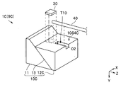
- the endoscope 9B of the modification 3 of the first embodiment shown in FIG. 6 has a groove T10 in which the tip of the optical fiber 40 is inserted in the upper surface 10S4C of the prism 10C of the imaging device 1B.
- the width of the groove T10 is set to be slightly larger than the outer diameter of the optical fiber 40.
- the groove T10 has the same function as the ferrule.
- the depth of the groove T10 is preferably such that the diameter of the tip can be further reduced by the optical fiber 40 having a depth such that the optical fiber 40 does not protrude from the groove T10 (the optical fiber 40 fits in the groove T10).
- the imaging device 1C is shorter and smaller than the imaging device 1 because it does not require a ferrule. For this reason, the endoscope 9C has a tip portion 90A shorter than the endoscope 9 and is less invasive.
- the second wiring board 52 on which the light emitting element 30C is mounted does not have a through hole which becomes an optical path, it has a side surface portion (not shown) for arranging in parallel with the light emitting surface 10S3.
- the configuration of the light emitting element 30C is different from that of the light emitting element 30, the configuration of the second wiring board is changed to be compatible with the light emitting element 30C, so the endoscope 9D has the same effect as the endoscope 9C and the like Have.
- the endoscope 9E according to the second embodiment is similar to the endoscope 9 and has the same effect.
- the prism 10E of the imaging device 1E of the endoscope 9E has only one triangular prism 11.
- the imaging device 1E further includes a second wiring board 53 disposed in parallel with the light emitting surface 10S3 in a space above the first reflective surface 10S2.
- the light emitting element 30 is mounted on the second wiring board, and the light signal is reflected by the back surface 10S5E of the first reflection surface 10S2.
- the second wiring board 53 has a frame-like side surface portion to be disposed in parallel with the emission surface 10S3. Further, the rear side surface portion of the second wiring board 53 has a through hole through which the ferrule 41E is inserted.
- the optical fiber 40 is positioned when the end face of the optical fiber 40 abuts on the triangular prism 11.
- the prism 10E of the imaging device 1E is simpler in construction and less expensive than the prism 10.
- a back surface 10S5E of the first reflection surface 10S2 may be coated with a reflection film such as aluminum or gold.
- the light signal is reflected not by the back surface 10S5E, but by the second reflection surface which is the surface of the reflection film parallel to the first reflection surface 10S2.
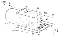
- the endoscope 9F of the third embodiment is similar to the endoscope 9 and has the same effect, so the components having the same functions will be assigned the same reference numerals and descriptions thereof will be omitted.
- the first reflection surface 10S2 of the prism 10 needs a large area.
- the light beam diameter of the optical signal is much smaller than the area of the light receiving unit 21 and is output from the light emitting unit 31 having a diameter of 10 ⁇ m, for example, the light emitting element 30 does not need a wide reflective surface. Further, the size of the light emitting element 30 is smaller than the size of the prism 10.
- the imaging device 1F of the endoscope 9F includes two light emitting elements 30F1 and 30F2 and two optical fibers 40F1 and 40F2. That is, two optical signals are reflected by one second reflection surface 10S5.
- the imaging device may include three or more light emitting elements 30 and three or more optical fibers 40 (ferrules 41).
- three or more optical fibers 40 are in a plane parallel to the incident surface 10S1, for example, the second It is preferable that the light emitting surface 10S6 be disposed in a zigzag manner with respect to the light emitting surface 10S6.
- the endoscope system 3A of the fourth embodiment is similar to the endoscope system 3 and has the same effect, so the same reference numerals are given to the components having the same functions, and the description will be omitted.
- an endoscope system 3A includes an endoscope 9, a light source 81A, an illumination optical system 96, an optical signal control unit 80A, and a timing control unit 80B.
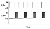
- the light source 81A of the light source device 81 generates pulsed illumination light that repeats irradiation / non-irradiation. For example, after generating the irradiation light for 1/60 seconds, the light source 81A does not generate the irradiation light for 1/60 seconds. That is, the light source 81A generates pulsed illumination light that emits light once in 1/30 seconds and repeats irradiation / non-irradiation.
- the illumination optical system 96 disposed at the distal end portion 90A of the insertion portion 90 emits the pulse illumination light generated by the light source 81A.
- the light signal control unit 80A of the processor 80 controls a period during which the light emitting element 30 outputs a light signal. Then, the timing control unit 80B controls the light source 81A and the light signal control unit 80A so that the irradiation period of the pulse illumination light and the output period in which the light emitting element 30 outputs the light signal do not overlap.
- the light signal is not output (OFF) during the irradiation period (ON) in which the light source 81A emits the illumination light.
- a light signal is output (ON) in the non-irradiation period (OFF) in which the light source 81A does not emit illumination light.
- the bonding prism 10 there is almost no interference between the imaging light incident on the first triangular prism 11 and the light signal incident on the second triangular prism 12, but it is not complete. Further, in the prism 10E, the imaging light and the light signal may interfere with each other.
- the light emitting element since the light emitting element outputs the light signal during the period in which the pulse illumination light is not irradiated, there is no possibility that the imaging light interferes with the light signal.
- the light signal control unit 80A and the timing control unit 80B may be independent CPUs, one CPU, or a part of the processor 80 processor.
- the light signal control unit 80A and the timing control unit 80B may be components of an endoscope.
- the endoscope 9 is a flexible mirror having a flexible insertion portion, it may be a rigid endoscope, and may be a medical endoscope or an industrial endoscope.
- imaging device 1X optical module 2: imaging optical system 3: endoscope system 9, 9A to 9G: endoscope 10: prism 10S1.
- Light emitting element 40 Optical fiber 41
- Ferrule 50 First wiring board 51-53 Second wiring board 55 Electronic parts 56 Bonding wire 60
Landscapes
- Health & Medical Sciences (AREA)
- Life Sciences & Earth Sciences (AREA)
- Surgery (AREA)
- Physics & Mathematics (AREA)
- Optics & Photonics (AREA)
- Engineering & Computer Science (AREA)
- Biophysics (AREA)
- Animal Behavior & Ethology (AREA)
- Pathology (AREA)
- Radiology & Medical Imaging (AREA)
- Veterinary Medicine (AREA)
- Biomedical Technology (AREA)
- Heart & Thoracic Surgery (AREA)
- Medical Informatics (AREA)
- Molecular Biology (AREA)
- Nuclear Medicine, Radiotherapy & Molecular Imaging (AREA)
- General Health & Medical Sciences (AREA)
- Public Health (AREA)
- Signal Processing (AREA)
- Astronomy & Astrophysics (AREA)
- General Physics & Mathematics (AREA)
- Instruments For Viewing The Inside Of Hollow Bodies (AREA)
- Endoscopes (AREA)
Abstract
La présente invention concerne un endoscope (9) comprenant un dispositif de capture d'image (1) qui est disposé au niveau d'une partie d'extrémité avant (90A) d'une section d'insertion (90). Le dispositif de capture d'image (1) comprend : un système optique de capture d'image (2); un prisme (10) ayant une surface d'entrée de lumière (10S1), une première surface réfléchissante (10S2) et une surface de sortie de lumière (10S2); un élément de capture d'image (20) ayant, sur une surface de réception de lumière (20SA), la surface de sortie de lumière (10S3) du prisme (10); et un élément électroluminescent (30), qui comporte une surface d'émission de lumière (30SA) disposée parallèlement à la surface de réception de lumière (20SA), et qui émet un signal optique sur la base d'un signal de capture d'image émis depuis l'élément de capture d'image (20). Le signal optique émis par l'élément électroluminescent (30) est réfléchi par une surface inverse (10S5E) de la première surface réfléchissante (10S2) ou par une seconde surface réfléchissante (10S5) parallèle à la première surface réfléchissante, et est guidé vers une fibre optique (40) qui envoie le signal optique.
Priority Applications (2)
| Application Number | Priority Date | Filing Date | Title |
|---|---|---|---|
| PCT/JP2017/037339 WO2019077643A1 (fr) | 2017-10-16 | 2017-10-16 | Endoscope et système d'endoscope |
| US16/846,832 US11344182B2 (en) | 2017-10-16 | 2020-04-13 | Endoscope and endoscope system |
Applications Claiming Priority (1)
| Application Number | Priority Date | Filing Date | Title |
|---|---|---|---|
| PCT/JP2017/037339 WO2019077643A1 (fr) | 2017-10-16 | 2017-10-16 | Endoscope et système d'endoscope |
Related Child Applications (1)
| Application Number | Title | Priority Date | Filing Date |
|---|---|---|---|
| US16/846,832 Continuation US11344182B2 (en) | 2017-10-16 | 2020-04-13 | Endoscope and endoscope system |
Publications (1)
| Publication Number | Publication Date |
|---|---|
| WO2019077643A1 true WO2019077643A1 (fr) | 2019-04-25 |
Family
ID=66173224
Family Applications (1)
| Application Number | Title | Priority Date | Filing Date |
|---|---|---|---|
| PCT/JP2017/037339 Ceased WO2019077643A1 (fr) | 2017-10-16 | 2017-10-16 | Endoscope et système d'endoscope |
Country Status (2)
| Country | Link |
|---|---|
| US (1) | US11344182B2 (fr) |
| WO (1) | WO2019077643A1 (fr) |
Families Citing this family (2)
| Publication number | Priority date | Publication date | Assignee | Title |
|---|---|---|---|---|
| JP7687926B2 (ja) * | 2021-10-01 | 2025-06-03 | Hoya株式会社 | 光送信モジュールおよび内視鏡 |
| US12121212B2 (en) * | 2022-02-04 | 2024-10-22 | Olympus Medical Systems Corp. | Insertion instrument, distal end portion of insertion instrument and manufacturing method of insertion instrument |
Citations (5)
| Publication number | Priority date | Publication date | Assignee | Title |
|---|---|---|---|---|
| JP2007260066A (ja) * | 2006-03-28 | 2007-10-11 | Pentax Corp | 内視鏡装置 |
| JP2008011504A (ja) * | 2006-05-29 | 2008-01-17 | Pentax Corp | 光信号送受信装置 |
| JP2013235243A (ja) * | 2012-04-09 | 2013-11-21 | Fujikura Ltd | 光路変更部材 |
| JP2014117520A (ja) * | 2012-12-18 | 2014-06-30 | Olympus Medical Systems Corp | 電子内視鏡 |
| JP2015024029A (ja) * | 2013-07-26 | 2015-02-05 | オリンパスメディカルシステムズ株式会社 | 内視鏡用撮像ユニット及びその組立方法 |
Family Cites Families (11)
| Publication number | Priority date | Publication date | Assignee | Title |
|---|---|---|---|---|
| DE3435598C2 (de) * | 1983-09-30 | 1986-06-19 | Olympus Optical Co., Ltd., Tokio/Tokyo | Endoskopanordnung |
| JP2003177286A (ja) | 2001-12-11 | 2003-06-27 | Hosiden Corp | 双方向光通信用光学部品 |
| JP2005352256A (ja) | 2004-06-11 | 2005-12-22 | Fujikura Ltd | 一心双方向光送受信モジュール用光部品及び一心双方向光送受信モジュール |
| EP1632804B1 (fr) | 2004-09-01 | 2008-06-04 | Barco, naamloze vennootschap. | Assemblage de prisme |
| US20070286231A1 (en) | 2006-05-29 | 2007-12-13 | Pentax Corporation | Optical signal transmitting and receiving apparatus |
| JP5238651B2 (ja) * | 2009-09-11 | 2013-07-17 | 株式会社フジクラ | 光路変更部材、光接続方法 |
| JP6021391B2 (ja) * | 2012-04-05 | 2016-11-09 | オリンパス株式会社 | 内視鏡 |
| JP2013254889A (ja) * | 2012-06-08 | 2013-12-19 | Idec Corp | 光源装置および照明装置 |
| JP6300442B2 (ja) | 2013-01-18 | 2018-03-28 | オリンパス株式会社 | 光伝送モジュールおよび撮像装置 |
| JP6178749B2 (ja) | 2014-04-07 | 2017-08-09 | 富士フイルム株式会社 | 内視鏡用撮像装置 |
| JP6445138B2 (ja) * | 2015-03-20 | 2018-12-26 | オリンパス株式会社 | 光伝送モジュール、内視鏡、および前記光伝送モジュールの製造方法 |
-
2017
- 2017-10-16 WO PCT/JP2017/037339 patent/WO2019077643A1/fr not_active Ceased
-
2020
- 2020-04-13 US US16/846,832 patent/US11344182B2/en active Active
Patent Citations (5)
| Publication number | Priority date | Publication date | Assignee | Title |
|---|---|---|---|---|
| JP2007260066A (ja) * | 2006-03-28 | 2007-10-11 | Pentax Corp | 内視鏡装置 |
| JP2008011504A (ja) * | 2006-05-29 | 2008-01-17 | Pentax Corp | 光信号送受信装置 |
| JP2013235243A (ja) * | 2012-04-09 | 2013-11-21 | Fujikura Ltd | 光路変更部材 |
| JP2014117520A (ja) * | 2012-12-18 | 2014-06-30 | Olympus Medical Systems Corp | 電子内視鏡 |
| JP2015024029A (ja) * | 2013-07-26 | 2015-02-05 | オリンパスメディカルシステムズ株式会社 | 内視鏡用撮像ユニット及びその組立方法 |
Also Published As
| Publication number | Publication date |
|---|---|
| US11344182B2 (en) | 2022-05-31 |
| US20200237194A1 (en) | 2020-07-30 |
Similar Documents
| Publication | Publication Date | Title |
|---|---|---|
| US11172812B2 (en) | Endoscope | |
| JP5839811B2 (ja) | 撮像ユニット及び内視鏡 | |
| US10281710B2 (en) | Imaging module and endoscope apparatus each having a flexible substrate divided into different regions where a chip having a transmission buffer and a drive signal cable are connected to the different regions | |
| JP5767414B2 (ja) | 内視鏡用撮像ユニット | |
| US9207412B2 (en) | Optical transmission module and endoscope | |
| JP2005525896A (ja) | 小型カメラヘッド | |
| US10819960B2 (en) | Endoscope | |
| US11478128B2 (en) | Endoscope with cover at distal end of cannula | |
| US10321815B2 (en) | Image pickup module and endoscope | |
| WO2018198158A1 (fr) | Endoscope et module d'imagerie | |
| WO2019207650A1 (fr) | Dispositif d'imagerie d'endoscope, endoscope et procédé de fabrication de dispositif d'imagerie d'endoscope | |
| JP6659826B2 (ja) | 光伝送モジュール及び内視鏡 | |
| WO2015045615A1 (fr) | Module d'imagerie et dispositif d'endoscope | |
| US11344182B2 (en) | Endoscope and endoscope system | |
| US11395582B2 (en) | Endoscope with optimized illumination pathway | |
| US11058285B2 (en) | Optical signal transmission module | |
| WO2020065757A1 (fr) | Dispositif d'imagerie endoscopique, endoscope, et procédé de production de dispositif d'imagerie endoscopique | |
| WO2018146806A1 (fr) | Module de optique et endoscope | |
| WO2020179067A1 (fr) | Transducteur optique endoscopique, dispositif d'imagerie endoscopique et endoscope | |
| JP6465449B2 (ja) | 光信号送信モジュール | |
| US20210382250A1 (en) | Manufacturing method for image pickup apparatus for endoscope, image pickup apparatus for endoscope, and endoscope | |
| WO2017077638A1 (fr) | Endoscope et module de transmission optique | |
| US20180307035A1 (en) | Optical transmission module and endoscope | |
| US20200379246A1 (en) | Optical module for endoscope, endoscope, and manufacturing method of optical module for endoscope |
Legal Events
| Date | Code | Title | Description |
|---|---|---|---|
| 121 | Ep: the epo has been informed by wipo that ep was designated in this application |
Ref document number: 17929419 Country of ref document: EP Kind code of ref document: A1 |
|
| NENP | Non-entry into the national phase |
Ref country code: DE |
|
| 122 | Ep: pct application non-entry in european phase |
Ref document number: 17929419 Country of ref document: EP Kind code of ref document: A1 |
|
| NENP | Non-entry into the national phase |
Ref country code: JP |