WO2019077653A1 - 筒部材、及び筒部材付きバーナー - Google Patents
筒部材、及び筒部材付きバーナー Download PDFInfo
- Publication number
- WO2019077653A1 WO2019077653A1 PCT/JP2017/037376 JP2017037376W WO2019077653A1 WO 2019077653 A1 WO2019077653 A1 WO 2019077653A1 JP 2017037376 W JP2017037376 W JP 2017037376W WO 2019077653 A1 WO2019077653 A1 WO 2019077653A1
- Authority
- WO
- WIPO (PCT)
- Prior art keywords
- cylindrical member
- burner
- holes
- gas
- food
- Prior art date
- Legal status (The legal status is an assumption and is not a legal conclusion. Google has not performed a legal analysis and makes no representation as to the accuracy of the status listed.)
- Ceased
Links
Images

Classifications
-
- F—MECHANICAL ENGINEERING; LIGHTING; HEATING; WEAPONS; BLASTING
- F23—COMBUSTION APPARATUS; COMBUSTION PROCESSES
- F23D—BURNERS
- F23D14/00—Burners for combustion of a gas, e.g. of a gas stored under pressure as a liquid
- F23D14/46—Details
- F23D14/48—Nozzles
- F23D14/58—Nozzles characterised by the shape or arrangement of the outlet or outlets from the nozzle, e.g. of annular configuration
-
- F—MECHANICAL ENGINEERING; LIGHTING; HEATING; WEAPONS; BLASTING
- F23—COMBUSTION APPARATUS; COMBUSTION PROCESSES
- F23D—BURNERS
- F23D14/00—Burners for combustion of a gas, e.g. of a gas stored under pressure as a liquid
- F23D14/02—Premix gas burners, i.e. in which gaseous fuel is mixed with combustion air upstream of the combustion zone
- F23D14/04—Premix gas burners, i.e. in which gaseous fuel is mixed with combustion air upstream of the combustion zone induction type, e.g. Bunsen burner
- F23D14/08—Premix gas burners, i.e. in which gaseous fuel is mixed with combustion air upstream of the combustion zone induction type, e.g. Bunsen burner with axial outlets at the burner head
-
- A—HUMAN NECESSITIES
- A47—FURNITURE; DOMESTIC ARTICLES OR APPLIANCES; COFFEE MILLS; SPICE MILLS; SUCTION CLEANERS IN GENERAL
- A47J—KITCHEN EQUIPMENT; COFFEE MILLS; SPICE MILLS; APPARATUS FOR MAKING BEVERAGES
- A47J37/00—Baking; Roasting; Grilling; Frying
- A47J37/06—Roasters; Grills; Sandwich grills
- A47J37/0623—Small-size cooking ovens, i.e. defining an at least partially closed cooking cavity
- A47J37/0647—Small-size cooking ovens, i.e. defining an at least partially closed cooking cavity with gas burners
-
- F—MECHANICAL ENGINEERING; LIGHTING; HEATING; WEAPONS; BLASTING
- F23—COMBUSTION APPARATUS; COMBUSTION PROCESSES
- F23D—BURNERS
- F23D14/00—Burners for combustion of a gas, e.g. of a gas stored under pressure as a liquid
- F23D14/46—Details
- F23D14/48—Nozzles
- F23D14/52—Nozzles for torches; for blow-pipes
-
- F—MECHANICAL ENGINEERING; LIGHTING; HEATING; WEAPONS; BLASTING
- F23—COMBUSTION APPARATUS; COMBUSTION PROCESSES
- F23D—BURNERS
- F23D2212/00—Burner material specifications
Definitions
- the present invention relates to a cylindrical member and a burner with a cylindrical member.
- an odorant having a specific odor has been added so that it can be detected quickly and easily by appealing to the sense of smell when it leaks.
- sulfur compounds such as mercaptan and sulfide are known, and these are used singly or as a mixture of several.
- the sulfur-containing compounds being used are trace amounts and have high odorizing effects, and the odor is generally perceived as a gas odor (see, for example, Patent Document 1).
- burning processing such as a gas burner
- burning processing may burn the surface of a foodstuff, or may be subjected to a rolling process in which water on the surface is blown away.
- the odorant added to fuel gas may adhere to a foodstuff as a gas smell, and the flavor of foodstuffs might worsen.
- the object of the present invention is to provide a cylinder member and a burner with a cylinder member which can improve the flavor of food subjected to roasting.
- the cylindrical member of the present invention has a hole attached to the tip of the gas burner to pass the combustion flame.
- the roasting process is performed by the combustion flame which has passed through the hole, the gas smell is not generated from the roasted food. It is presumed that the gas smell is reduced by the complete combustion of the combustion flame and the generation of far infrared rays. Therefore, the flavor of the processed food can be improved.
- a plurality of holes are formed, one of the plurality of holes is formed at a central position in a direction orthogonal to the direction in which the combustion flame is output, and the holes excluding one of the plurality of holes are It is preferable to form along the circumferential direction centering on one. That is, by forming the plurality of holes at predetermined positions, a large amount of oxygen can be taken into the combustion flame. As a result, since the combustion flame to be output can be brought into a state of complete combustion, the gas odor can be further reduced, and the flavor of the processed food can be further improved.
- the material containing carbon it is preferable to be comprised with the material containing carbon. According to this, since the flavor of the charcoal can be attached to the food, the flavor of the roasted food can be further improved.
- the burner with a cylinder member of the present invention comprises a gas burner and the cylinder member according to any one of claims 1 to 3, and the cylinder member is at the tip of the gas burner. It is attached. According to this, it is possible to improve the flavor of the food subjected to roasting processing.
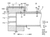
- FIG. 4 is a cross-sectional view taken along the line II in FIG. 3;
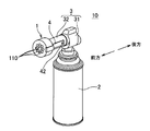
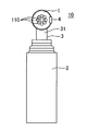
- FIG. 1 is a perspective view showing a cylinder member-equipped burner 10 including a cylinder member 1 according to an embodiment of the present invention.
- the axial direction of the cylindrical member 1 may be referred to as "front-back direction”, and the direction in which the combustion flame is output may be referred to as "forward”.
- the cylinder member-equipped burner 10 supplies oxygen to the gas cylinder 2 filled with LP gas (liquefied propane gas) and the LP gas delivered from the gas cylinder 2 to output a combustion flame.
- LP gas liquefied propane gas
- a gas burner 3 is provided, a cylindrical member 1 attached to the tip of the gas burner 3 for passing the combustion flame, and a support member 4 for supporting the cylindrical member 1 on the gas burner 3.
- the gas burner 3 adjusts the amount of gas sent out from the gas cylinder 2 and also adjusts the adjustment mechanism 31 for taking in air (oxygen) mixed in the gas, and the combustion flame sent out from the adjustment mechanism 31 in a predetermined direction And a metal pipe 32 for outputting in the direction.
- the metal pipe 32 is formed with a screw hole 33 in which the screw 42 of the support member 4 is screwed. As shown in FIG. 4, the screw hole 33 is in a state in which the screw 42 is screwed (hereinafter sometimes referred to as screwed) and a boundary portion between the main body portion 11 of the cylindrical member 1 and the insertion cylindrical portion 12 An axial gap S4 is formed between the metal pipe 32 and the metal pipe 32 so as to be open.
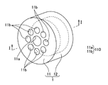
- the cylindrical member 1 is made of an isotropic graphite material in the present embodiment. As shown in FIGS. 3 to 5, the cylindrical member 1 is erected in a cylindrical shape from the periphery of the main body 11 and a disk-shaped main body 11 in which a plurality of (nine in the illustrated example) through holes are formed. And an insertion cylinder 12 into which the metal pipe 32 of the gas burner 3 is inserted.
- the main body 11 is formed such that the axial dimension L2 has a predetermined thickness, and a plurality of (9 in the illustrated example) planar views penetrating in the axial direction Are configured to have a circular through hole 110.
- the central hole 11a is formed at the center position (the same position as the central point P of the main body portion 11) of the disk-like main body portion 11 There is.
- the remaining eight through holes are formed around the center position and at equal intervals.
- the diameter of the central hole 11a is formed to be slightly larger than the diameter of the remaining eight through holes (which may be hereinafter referred to as peripheral holes) described later.
- the nine through holes 110 are formed such that the axial forward end (the direction in which the combustion flame is output) (front end) 111 communicates with the outside, and the axial rear end (rear end)
- the reference numeral 112 is formed to communicate with the inside of the insertion cylinder 12.
- the nine through holes 110 are formed so that the inner diameter dimension is substantially constant from the front end 111 to the rear end 112.
- the insertion cylindrical portion 12 is formed coaxially with the main body portion 11, and the outer diameter size of the insertion cylindrical portion 12 is substantially equal to the outer diameter size of the main body portion R1 (the outer diameter size R1 of the cylindrical portion 1 It is formed to be). Further, the inner diameter dimension R2 of the insertion cylindrical portion 12 is formed to be larger than the outer diameter dimension of the metal pipe 32 of the gas burner 3. That is, as shown in FIG. 4, in the state where the end of the metal pipe 32 is inserted into the insertion cylindrical portion 12, a clearance S1 is made in the radial direction between the insertion cylindrical portion 12 and the metal pipe 32. Is formed.
- the cylindrical member 1 has an axial dimension L1 of 25 mm, an axial dimension L2 of the main body 11 of 12.5 mm, an axial dimension L3 of the insertion cylindrical portion 12 of 12.5 mm, and the cylindrical member 1.
- the inner diameter R2 of the insertion cylinder 12 is 22 mm, the diameter R3 of the center hole 11a is 6 mm, and the diameter R4 of the peripheral holes is 5 mm.
- the above-described dimensions and the like are merely examples, and in the present invention, the dimensions may be appropriately designed according to the diameter dimension of the metal pipe, the thermal power, the application, etc.
- the axial dimension L2 of the main body 11 is 10 mm to 55 mm
- the axial dimension L3 of the insertion cylinder 12 is 5 mm to 50 mm
- the outer diameter R1 of the cylinder 1 is 35 mm to 37 mm
- the inner diameter of the insertion cylinder 12 It is preferable that R2 be 21 mm to 23 mm
- the diameter R3 of the central hole 11a be 5 mm to 7 mm
- the diameter R4 of the peripheral holes be 4 mm to 6 mm.
- each through-hole 110 is formed so that an internal diameter size may become substantially constant from the front end part 111 to the back end part 112, this invention is not limited to this.
- Each through hole may be formed such that the diameter thereof gradually increases toward the front end 111, and may be formed such that the diameter thereof gradually decreases toward the front end 111. .
- the support member 4 is a plate member 41 obtained by bending a rectangular plate-like sheet metal and screws 42 for fixing the plate member 41 to the metal pipe 32. And have.
- the plate member 41 is, as shown in FIG. 4, a first plate portion 41A extending in the radial direction of the cylinder member 1 and a second plate continuous with the first plate portion 41A and extending in the axial direction of the cylinder member 1.
- a plate portion 41B, a third plate portion 41C continuous to the second plate portion 41B and extending in the radial direction of the cylindrical member 1, and a third plate portion 41C continuous to the axial direction of the cylindrical member 1 It has 4th board part 41D, and is comprised. That is, the first plate portion 41A and the third plate portion 41C are formed to face each other.
- the axial dimension of the second plate portion 41B is formed to be slightly larger than the axial dimension L1 of the cylindrical member 1.
- the fourth plate portion 41D is formed with a screw hole 43 into which the screw 42 is screwed.
- the gap S2 is formed between the first plate portion 41A and the third plate portion 41C and the axial direction of the cylindrical member 1 so as to be open. Further, the diameter dimension of the third plate portion 41C is formed in such a dimension that the gap S3 is open between the insertion tube portion 12 and the second plate portion 41B in the radial direction in a state in which the screw 42 is screwed. There is.
- the gaps S1, S2, S3, and S4 are formed so as to be open between the cylindrical member 1 and the support member 4 and the metal pipe 32, thereby the gap S1. , S2, S3, and S4 make it easy for air to be taken into the combustion flame passing through the through hole 110.
- the cylindrical member 1 is inserted with the insertion cylindrical portion 12 close to the tip of the metal pipe 32 with the axial direction oriented along the axial direction of the metal pipe 32 of the gas burner 3.
- the screw 42 is communicated with the screw hole 43 of the support member 4 and the metal pipe 32. Screw into screw hole 33.
- the cylindrical member 1 is attached to the gas burner 3.
- the cooking process is performed by the combustion flame that has passed through the through hole 110 (the hole portion), so that the gas smell does not occur from the food subjected to the baking process. It is presumed that the gas smell is reduced by the complete combustion of the combustion flame and the generation of far infrared rays. Therefore, the flavor of the processed food can be improved.
- a plurality of through holes 110 are formed, and one (center hole 11a) of the plurality of holes is formed at a central position in a direction orthogonal to the direction in which the combustion flame is output.
- Holes (peripheral holes 11b) excluding one (central hole 11a) of the portions are formed side by side in the circumferential direction centering on one (central hole 11a). That is, by forming the plurality of through holes 110 (holes) at predetermined positions, a large amount of oxygen can be taken into the combustion flame. As a result, since the combustion flame to be output can be brought into a state of complete combustion, the gas odor can be further reduced, and the flavor of the processed food can be further improved.
- the cylindrical member 1 is comprised with the material (isotropic graphite material) containing carbon. According to this, since the flavor of the charcoal can be attached to the food, the flavor of the roasted food can be further improved.
- materials containing carbon various graphite materials, charcoal, bamboo charcoal, coal (coke) and the like can be used.
- the cylinder member 1 is comprised with the isotropic graphite material, this invention is not limited to this.
- the cylindrical member 1 may be made of ceramic or various metals. Even when the tubular member 1 is made of these metals, no gas smell is generated from the food subjected to the roasting process. That is, although the flavor is inferior to that in the first embodiment by the extent that the flavor of the charcoal does not adhere to the food, the flavor of the food subjected to the roasting process can be improved.
- the gaps S1, S2, S3 and S4 are formed between the cylindrical member 1 and the support member 4 and the metal pipe 32 while the screw 42 is screwed.
- the invention is not limited to this.
- the gap located between the cylindrical member 1 and the support member 4 and the metal pipe 32 may be appropriately provided according to the application and the required performance, and the gaps S1 and S2 Even if it is a cylindrical member designed so that S3, S4 may not arise, it shall be included in the right range of this invention.
- the inventors of the present invention confirmed the effects of the present invention by causing 30 subjects to sample the following food.
- a subject to sample food referred to as food 1
- food 1 After subjecting a subject to sample food (referred to as food 1) which has been subjected to cooking processing with a gas burner 3 without the cylindrical member 1 attached thereto, the following three foods were sampled.
- food 1 answer A if you feel the taste is better, answer B if you feel the taste does not change, answer C if you feel the taste is worse It was made to do.
Landscapes
- Engineering & Computer Science (AREA)
- Chemical & Material Sciences (AREA)
- Combustion & Propulsion (AREA)
- Mechanical Engineering (AREA)
- General Engineering & Computer Science (AREA)
- Food Science & Technology (AREA)
- Baking, Grill, Roasting (AREA)
- Gas Burners (AREA)
- General Preparation And Processing Of Foods (AREA)
- Meat, Egg Or Seafood Products (AREA)
Abstract
Description
2)セラミックで構成された筒部材を有する筒部材付きバーナーで食材に炙り加工を施した食品
3)食材に炙り加工を施していない食品
2)について、被験者30名のうち23名がAと回答し、残り7名がBと回答した。
3)について、被験者30名のうち3名がAと回答し、5名がBと回答し、残り22名がCと回答した。以上の結果から、本発明の優れた食味向上効果を確認することができた。
3 ガスバーナー
10 筒部材付きバーナー
110 貫通孔(孔部)
11a 中心孔(複数の孔部のうち1つ)
11b 周囲の孔(複数の孔部のうち前記1つを除く孔部)
Claims (4)
- ガスバーナーの先端部に取り付けられて、その燃焼炎を通過させる孔部を有することを特徴とする筒部材。
- 前記孔部が、複数形成され、
前記複数の孔部のうち1つが、燃焼炎が出力する方向に直交する方向の中心位置に形成され、
前記複数の孔部のうち前記1つを除く孔部が、前記1つを中心とする周方向に並んで形成されていることを特徴とする請求項1に記載の筒部材。 - 炭素を含む材料で構成されていることを特徴とする請求項1または請求項2に記載の筒部材。
- ガスバーナーと、
請求項1~請求項3のうち何れか一項に記載の筒部材と、を備え、
前記筒部材が、前記ガスバーナーの先端部に取り付けられていることを特徴とする筒部材付きバーナー。
Priority Applications (13)
| Application Number | Priority Date | Filing Date | Title |
|---|---|---|---|
| NZ758782A NZ758782A (en) | 2017-10-16 | 2017-10-16 | Cooking burner and roasting processing method |
| US16/610,104 US11313555B2 (en) | 2017-10-16 | 2017-10-16 | Cooking burner and roasting processing method |
| JP2018558448A JP6494063B6 (ja) | 2017-10-16 | 2017-10-16 | 調理用バーナー、及び炙り加工方法 |
| CN201780091401.4A CN110720015B (zh) | 2017-10-16 | 2017-10-16 | 烹调用燃烧器、以及炙烤加工方法 |
| AU2017436554A AU2017436554B2 (en) | 2017-10-16 | 2017-10-16 | Cylindrical member and cylindrical member-equipped burner |
| PCT/JP2017/037376 WO2019077653A1 (ja) | 2017-10-16 | 2017-10-16 | 筒部材、及び筒部材付きバーナー |
| DK17929376.6T DK3614050T3 (da) | 2017-10-16 | 2017-10-16 | Grillbrænder og grillprocesfremgangsmåde med anvendelse af samme |
| ES17929376T ES2894949T3 (es) | 2017-10-16 | 2017-10-16 | Quemador de tostado y método de procesamiento de tostado que utiliza el mismo |
| CA3079150A CA3079150C (en) | 2017-10-16 | 2017-10-16 | Cooking burner and roasting processing method |
| SG11202003511PA SG11202003511PA (en) | 2017-10-16 | 2017-10-16 | Cooking burner and roasting processing method |
| PL17929376T PL3614050T3 (pl) | 2017-10-16 | 2017-10-16 | Palnik do prażenia i sposób obróbki prażeniem tym palnikiem |
| EP17929376.6A EP3614050B1 (en) | 2017-10-16 | 2017-10-16 | Roasting burner and roasting processing method using the same |
| PT179293766T PT3614050T (pt) | 2017-10-16 | 2017-10-16 | Maçarico de assar e método de processamento de assadura utilizando o mesmo |
Applications Claiming Priority (1)
| Application Number | Priority Date | Filing Date | Title |
|---|---|---|---|
| PCT/JP2017/037376 WO2019077653A1 (ja) | 2017-10-16 | 2017-10-16 | 筒部材、及び筒部材付きバーナー |
Publications (1)
| Publication Number | Publication Date |
|---|---|
| WO2019077653A1 true WO2019077653A1 (ja) | 2019-04-25 |
Family
ID=66092512
Family Applications (1)
| Application Number | Title | Priority Date | Filing Date |
|---|---|---|---|
| PCT/JP2017/037376 Ceased WO2019077653A1 (ja) | 2017-10-16 | 2017-10-16 | 筒部材、及び筒部材付きバーナー |
Country Status (13)
| Country | Link |
|---|---|
| US (1) | US11313555B2 (ja) |
| EP (1) | EP3614050B1 (ja) |
| JP (1) | JP6494063B6 (ja) |
| CN (1) | CN110720015B (ja) |
| AU (1) | AU2017436554B2 (ja) |
| CA (1) | CA3079150C (ja) |
| DK (1) | DK3614050T3 (ja) |
| ES (1) | ES2894949T3 (ja) |
| NZ (1) | NZ758782A (ja) |
| PL (1) | PL3614050T3 (ja) |
| PT (1) | PT3614050T (ja) |
| SG (1) | SG11202003511PA (ja) |
| WO (1) | WO2019077653A1 (ja) |
Families Citing this family (1)
| Publication number | Priority date | Publication date | Assignee | Title |
|---|---|---|---|---|
| US11499713B2 (en) * | 2020-07-22 | 2022-11-15 | Rene Sura | Handheld welding torch apparatus |
Citations (5)
| Publication number | Priority date | Publication date | Assignee | Title |
|---|---|---|---|---|
| JPS59103012U (ja) * | 1982-12-22 | 1984-07-11 | 株式会社ニツコ− | 耐熱バ−ナ−装置 |
| JPS59186608U (ja) * | 1983-05-27 | 1984-12-11 | 株式会社 ニツコ− | 耐熱バ−ナ−装置 |
| JPH0860167A (ja) | 1994-08-24 | 1996-03-05 | Tokyo Gas Co Ltd | 燃料ガス用付臭剤 |
| US20040202978A1 (en) * | 2003-04-11 | 2004-10-14 | Wong Ming King | Lighter nozzle system for producing stylish torch |
| JP2007510886A (ja) * | 2003-11-10 | 2007-04-26 | ズィッポー マニュファクチャリング カンパニ | 同心バーナー |
Family Cites Families (17)
| Publication number | Priority date | Publication date | Assignee | Title |
|---|---|---|---|---|
| DE206052C (ja) * | ||||
| US3352492A (en) * | 1960-08-02 | 1967-11-14 | Powder Melting Corp | Method of and apparatus for depositing metal powder |
| GB958907A (en) * | 1962-02-28 | 1964-05-27 | Babcock & Wilcox Ltd | Improvements in or relating to air registers |
| JPS6440188A (en) * | 1987-08-07 | 1989-02-10 | Sumitomo Metal Ind | Multi-layer clad steel excellent in thermal conductivity |
| US5186620A (en) * | 1991-04-01 | 1993-02-16 | Beckett Gas, Inc. | Gas burner nozzle |
| JP3580325B2 (ja) * | 1995-06-07 | 2004-10-20 | リンナイ株式会社 | 表面燃焼バーナ |
| US5588825A (en) * | 1995-12-13 | 1996-12-31 | Governers Of The University Of Alberta | Lean premixed fuel burner |
| JP2957952B2 (ja) * | 1996-07-10 | 1999-10-06 | 株式会社はや | 加熱調理装置 |
| JP4212495B2 (ja) * | 2004-02-06 | 2009-01-21 | 木村 毅和 | 放射熱及び伝導熱を発生させる高温加熱装置とマイクロ波照射装置、並びに加熱装置の上下移動機構を備えた、オーブンケースの庫内に独立した形で設置された両面加熱調理機、及びその製造方法。 |
| JP3125015U (ja) * | 2006-06-14 | 2006-09-07 | 隆志 市原 | ガスバーナー火炎噴射ノズル用キャップ |
| JP2011114863A (ja) * | 2009-11-23 | 2011-06-09 | Samsung Electronics Co Ltd | 3D映像の提供方法、3D映像の変換方法、GUI提供方法及びこれを適用した3Dディスプレイ装置、そして3D映像の提供システム{Methodforproviding3Dimage、methodforconverting3Dimage、GUIprovidingmethodrelatedto3Dimageand3Ddisplayapparatusandsystemforproviding3Dimage} |
| TW201437563A (zh) * | 2013-03-22 | 2014-10-01 | Shang-Yuan Huang | 節能燃氣系統 |
| CN203273902U (zh) * | 2013-05-24 | 2013-11-06 | 青岛兴邦烤箱有限公司 | 一种用于烤箱的经济型燃烧器 |
| CN104566369B (zh) | 2014-12-10 | 2016-08-31 | 练志伟 | 一种食品烘焙喷火管 |
| CN104566368B (zh) * | 2014-12-10 | 2016-09-14 | 练志伟 | 可排湿的食品烘焙喷火管 |
| CN105465786A (zh) * | 2015-12-08 | 2016-04-06 | 上海华之邦科技股份有限公司 | 一种适用各种低热值/低压力燃气的低NOx燃烧器 |
| CN105650639A (zh) * | 2016-02-04 | 2016-06-08 | 中国科学院工程热物理研究所 | 一种多喷孔喷嘴、喷嘴阵列和燃烧器 |
-
2017
- 2017-10-16 PL PL17929376T patent/PL3614050T3/pl unknown
- 2017-10-16 WO PCT/JP2017/037376 patent/WO2019077653A1/ja not_active Ceased
- 2017-10-16 AU AU2017436554A patent/AU2017436554B2/en active Active
- 2017-10-16 SG SG11202003511PA patent/SG11202003511PA/en unknown
- 2017-10-16 US US16/610,104 patent/US11313555B2/en active Active
- 2017-10-16 CN CN201780091401.4A patent/CN110720015B/zh active Active
- 2017-10-16 ES ES17929376T patent/ES2894949T3/es active Active
- 2017-10-16 NZ NZ758782A patent/NZ758782A/en unknown
- 2017-10-16 CA CA3079150A patent/CA3079150C/en active Active
- 2017-10-16 PT PT179293766T patent/PT3614050T/pt unknown
- 2017-10-16 EP EP17929376.6A patent/EP3614050B1/en active Active
- 2017-10-16 JP JP2018558448A patent/JP6494063B6/ja active Active
- 2017-10-16 DK DK17929376.6T patent/DK3614050T3/da active
Patent Citations (5)
| Publication number | Priority date | Publication date | Assignee | Title |
|---|---|---|---|---|
| JPS59103012U (ja) * | 1982-12-22 | 1984-07-11 | 株式会社ニツコ− | 耐熱バ−ナ−装置 |
| JPS59186608U (ja) * | 1983-05-27 | 1984-12-11 | 株式会社 ニツコ− | 耐熱バ−ナ−装置 |
| JPH0860167A (ja) | 1994-08-24 | 1996-03-05 | Tokyo Gas Co Ltd | 燃料ガス用付臭剤 |
| US20040202978A1 (en) * | 2003-04-11 | 2004-10-14 | Wong Ming King | Lighter nozzle system for producing stylish torch |
| JP2007510886A (ja) * | 2003-11-10 | 2007-04-26 | ズィッポー マニュファクチャリング カンパニ | 同心バーナー |
Non-Patent Citations (1)
| Title |
|---|
| See also references of EP3614050A4 |
Also Published As
| Publication number | Publication date |
|---|---|
| CN110720015A (zh) | 2020-01-21 |
| PT3614050T (pt) | 2021-10-20 |
| CA3079150C (en) | 2021-09-14 |
| EP3614050B1 (en) | 2021-08-25 |
| AU2017436554A1 (en) | 2019-11-21 |
| JP6494063B1 (ja) | 2019-04-10 |
| PL3614050T3 (pl) | 2022-01-03 |
| CN110720015B (zh) | 2021-05-25 |
| EP3614050A4 (en) | 2020-06-03 |
| AU2017436554B2 (en) | 2020-12-03 |
| CA3079150A1 (en) | 2019-04-25 |
| DK3614050T3 (da) | 2021-10-25 |
| US20200080721A1 (en) | 2020-03-12 |
| ES2894949T3 (es) | 2022-02-16 |
| JPWO2019077653A1 (ja) | 2019-11-14 |
| JP6494063B6 (ja) | 2019-06-19 |
| US11313555B2 (en) | 2022-04-26 |
| EP3614050A1 (en) | 2020-02-26 |
| SG11202003511PA (en) | 2020-05-28 |
| NZ758782A (en) | 2021-12-24 |
Similar Documents
| Publication | Publication Date | Title |
|---|---|---|
| WO2007076292A3 (en) | Pellet-fired barbecue | |
| WO2008030566A3 (en) | Pellet burning heating assembly | |
| AR029550A1 (es) | Quemador con espaciador interior | |
| US9669500B2 (en) | Cooking device for a solid-fuel cooker including fuel container and solid cover and related methods | |
| US20110214342A1 (en) | Artificial fireplace log with combustion illuminated message or image | |
| WO2007033306A3 (en) | Gas turbine engine combustion systems | |
| JP6494063B6 (ja) | 調理用バーナー、及び炙り加工方法 | |
| EP4115067A4 (en) | NATURAL GAS ENGINES WITH FUEL QUALITY DETERMINATION | |
| TWI757335B (zh) | 燃燒器的點火裝置 | |
| FI20060914A7 (fi) | Kaasumoottori ja sytytyslaite kaasumoottoria varten | |
| ES2557413A1 (es) | Estufa de combustión | |
| ATE525614T1 (de) | Kohlenstaubbrenner für niedrige nox-emissionen | |
| BRPI0801968A2 (pt) | queimador a gás gerador de vapor | |
| WO2009003439A3 (de) | Brennstoff zum beheizen einer einrichtung zum grillen | |
| HK40016372A (en) | Cooking burner, and grill processing method | |
| HK40016372B (en) | Cooking burner, and grill processing method | |
| JP6388492B2 (ja) | グリル | |
| TW200716891A (en) | O-ring and clamp-type joint for vacuum apparatus | |
| EP3752771A4 (en) | BURNERS, BURNER ARRANGEMENTS AND METHODS OF IGNITING FUEL | |
| US20220408967A1 (en) | Segmented Porous Barbeque Grill Grate | |
| GB2471296A (en) | Smoke generator for use in the cold smoking of foodstuffs | |
| AU2015100528A4 (en) | Grid assembly with detachable legs. | |
| CN202337767U (zh) | 煤气发生炉 | |
| CN104154540A (zh) | 一种喷火器 | |
| TR202004461U4 (tr) | Kamp Kuzinesi |
Legal Events
| Date | Code | Title | Description |
|---|---|---|---|
| ENP | Entry into the national phase |
Ref document number: 2018558448 Country of ref document: JP Kind code of ref document: A |
|
| 121 | Ep: the epo has been informed by wipo that ep was designated in this application |
Ref document number: 17929376 Country of ref document: EP Kind code of ref document: A1 |
|
| ENP | Entry into the national phase |
Ref document number: 2017436554 Country of ref document: AU Date of ref document: 20171016 Kind code of ref document: A |
|
| ENP | Entry into the national phase |
Ref document number: 2017929376 Country of ref document: EP Effective date: 20191118 |
|
| ENP | Entry into the national phase |
Ref document number: 3079150 Country of ref document: CA |
|
| NENP | Non-entry into the national phase |
Ref country code: DE |