WO2019077902A1 - Dispositif de refroidissement - Google Patents
Dispositif de refroidissement Download PDFInfo
- Publication number
- WO2019077902A1 WO2019077902A1 PCT/JP2018/033047 JP2018033047W WO2019077902A1 WO 2019077902 A1 WO2019077902 A1 WO 2019077902A1 JP 2018033047 W JP2018033047 W JP 2018033047W WO 2019077902 A1 WO2019077902 A1 WO 2019077902A1
- Authority
- WO
- WIPO (PCT)
- Prior art keywords
- outdoor
- heat
- condensation
- working fluid
- condensing
- Prior art date
- Legal status (The legal status is an assumption and is not a legal conclusion. Google has not performed a legal analysis and makes no representation as to the accuracy of the status listed.)
- Ceased
Links
Images















Classifications
-
- B—PERFORMING OPERATIONS; TRANSPORTING
- B60—VEHICLES IN GENERAL
- B60K—ARRANGEMENT OR MOUNTING OF PROPULSION UNITS OR OF TRANSMISSIONS IN VEHICLES; ARRANGEMENT OR MOUNTING OF PLURAL DIVERSE PRIME-MOVERS IN VEHICLES; AUXILIARY DRIVES FOR VEHICLES; INSTRUMENTATION OR DASHBOARDS FOR VEHICLES; ARRANGEMENTS IN CONNECTION WITH COOLING, AIR INTAKE, GAS EXHAUST OR FUEL SUPPLY OF PROPULSION UNITS IN VEHICLES
- B60K1/00—Arrangement or mounting of electrical propulsion units
- B60K1/04—Arrangement or mounting of electrical propulsion units of the electric storage means for propulsion
-
- B—PERFORMING OPERATIONS; TRANSPORTING
- B60—VEHICLES IN GENERAL
- B60K—ARRANGEMENT OR MOUNTING OF PROPULSION UNITS OR OF TRANSMISSIONS IN VEHICLES; ARRANGEMENT OR MOUNTING OF PLURAL DIVERSE PRIME-MOVERS IN VEHICLES; AUXILIARY DRIVES FOR VEHICLES; INSTRUMENTATION OR DASHBOARDS FOR VEHICLES; ARRANGEMENTS IN CONNECTION WITH COOLING, AIR INTAKE, GAS EXHAUST OR FUEL SUPPLY OF PROPULSION UNITS IN VEHICLES
- B60K11/00—Arrangement in connection with cooling of propulsion units
- B60K11/06—Arrangement in connection with cooling of propulsion units with air cooling
-
- F—MECHANICAL ENGINEERING; LIGHTING; HEATING; WEAPONS; BLASTING
- F28—HEAT EXCHANGE IN GENERAL
- F28D—HEAT-EXCHANGE APPARATUS, NOT PROVIDED FOR IN ANOTHER SUBCLASS, IN WHICH THE HEAT-EXCHANGE MEDIA DO NOT COME INTO DIRECT CONTACT
- F28D15/00—Heat-exchange apparatus with the intermediate heat-transfer medium in closed tubes passing into or through the conduit walls ; Heat-exchange apparatus employing intermediate heat-transfer medium or bodies
- F28D15/02—Heat-exchange apparatus with the intermediate heat-transfer medium in closed tubes passing into or through the conduit walls ; Heat-exchange apparatus employing intermediate heat-transfer medium or bodies in which the medium condenses and evaporates, e.g. heat pipes
-
- H—ELECTRICITY
- H01—ELECTRIC ELEMENTS
- H01M—PROCESSES OR MEANS, e.g. BATTERIES, FOR THE DIRECT CONVERSION OF CHEMICAL ENERGY INTO ELECTRICAL ENERGY
- H01M10/00—Secondary cells; Manufacture thereof
- H01M10/60—Heating or cooling; Temperature control
- H01M10/61—Types of temperature control
- H01M10/613—Cooling or keeping cold
-
- H—ELECTRICITY
- H01—ELECTRIC ELEMENTS
- H01M—PROCESSES OR MEANS, e.g. BATTERIES, FOR THE DIRECT CONVERSION OF CHEMICAL ENERGY INTO ELECTRICAL ENERGY
- H01M10/00—Secondary cells; Manufacture thereof
- H01M10/60—Heating or cooling; Temperature control
- H01M10/62—Heating or cooling; Temperature control specially adapted for specific applications
- H01M10/625—Vehicles
-
- H—ELECTRICITY
- H01—ELECTRIC ELEMENTS
- H01M—PROCESSES OR MEANS, e.g. BATTERIES, FOR THE DIRECT CONVERSION OF CHEMICAL ENERGY INTO ELECTRICAL ENERGY
- H01M10/00—Secondary cells; Manufacture thereof
- H01M10/60—Heating or cooling; Temperature control
- H01M10/64—Heating or cooling; Temperature control characterised by the shape of the cells
- H01M10/647—Prismatic or flat cells, e.g. pouch cells
-
- H—ELECTRICITY
- H01—ELECTRIC ELEMENTS
- H01M—PROCESSES OR MEANS, e.g. BATTERIES, FOR THE DIRECT CONVERSION OF CHEMICAL ENERGY INTO ELECTRICAL ENERGY
- H01M10/00—Secondary cells; Manufacture thereof
- H01M10/60—Heating or cooling; Temperature control
- H01M10/65—Means for temperature control structurally associated with the cells
- H01M10/653—Means for temperature control structurally associated with the cells characterised by electrically insulating or thermally conductive materials
-
- H—ELECTRICITY
- H01—ELECTRIC ELEMENTS
- H01M—PROCESSES OR MEANS, e.g. BATTERIES, FOR THE DIRECT CONVERSION OF CHEMICAL ENERGY INTO ELECTRICAL ENERGY
- H01M10/00—Secondary cells; Manufacture thereof
- H01M10/60—Heating or cooling; Temperature control
- H01M10/65—Means for temperature control structurally associated with the cells
- H01M10/655—Solid structures for heat exchange or heat conduction
- H01M10/6552—Closed pipes transferring heat by thermal conductivity or phase transition, e.g. heat pipes
-
- H—ELECTRICITY
- H01—ELECTRIC ELEMENTS
- H01M—PROCESSES OR MEANS, e.g. BATTERIES, FOR THE DIRECT CONVERSION OF CHEMICAL ENERGY INTO ELECTRICAL ENERGY
- H01M10/00—Secondary cells; Manufacture thereof
- H01M10/60—Heating or cooling; Temperature control
- H01M10/65—Means for temperature control structurally associated with the cells
- H01M10/656—Means for temperature control structurally associated with the cells characterised by the type of heat-exchange fluid
- H01M10/6569—Fluids undergoing a liquid-gas phase change or transition, e.g. evaporation or condensation
-
- Y—GENERAL TAGGING OF NEW TECHNOLOGICAL DEVELOPMENTS; GENERAL TAGGING OF CROSS-SECTIONAL TECHNOLOGIES SPANNING OVER SEVERAL SECTIONS OF THE IPC; TECHNICAL SUBJECTS COVERED BY FORMER USPC CROSS-REFERENCE ART COLLECTIONS [XRACs] AND DIGESTS
- Y02—TECHNOLOGIES OR APPLICATIONS FOR MITIGATION OR ADAPTATION AGAINST CLIMATE CHANGE
- Y02E—REDUCTION OF GREENHOUSE GAS [GHG] EMISSIONS, RELATED TO ENERGY GENERATION, TRANSMISSION OR DISTRIBUTION
- Y02E60/00—Enabling technologies; Technologies with a potential or indirect contribution to GHG emissions mitigation
- Y02E60/10—Energy storage using batteries
Definitions
- the present disclosure relates to a cooling device that cools a target device such as, for example, a secondary battery for a vehicle.
- Patent Document 1 describes a cooling device for cooling a secondary battery for a vehicle.
- the cooling device of the patent document 1 is comprised by the heat pipe which utilized gravity for the reflux of the working fluid of a liquid phase. Further, since the entire cooling device is installed in the cabin space, the heat of the secondary battery is dissipated to the inside air.
- the cooling device of patent document 1 is comprised by the heat pipe, it is easy to cool an object apparatus uniformly, suppressing the temperature nonuniformity of an object apparatus. Furthermore, in the heat pipe, since the heat radiating portion (in other words, the condensation portion) can radiate heat collectively, it is easy to suppress the blowing noise by downsizing the blower that blows the heat radiating portion.
- the cooling device of Patent Document 1 radiates heat to the inside air, there is a possibility that the occupant may feel uncomfortable. In order to prevent such discomfort of the occupant, heat radiation to the outside air is effective. Therefore, when the outside air can be used to cool the target device, it is preferable to use the outside air.
- thermosiphon which is 1 type of a heat pipe.
- the present disclosure provides a cooling device that can cool a target device by radiating heat to the outside air, and that can arrange the target device on the compartment space side with respect to the vehicle body with a simple structure.
- the purpose is to
- a cooling device is A thermosiphon mounted on a vehicle and configured to perform heat transfer by phase change between a liquid phase and a gas phase of a working fluid sealed in a sealed container, and cooling the target device by the heat transfer,
- An evaporation unit that constitutes a part of the closed container and evaporates the working fluid by absorbing heat from the target device to the working fluid;
- a member that constitutes a part of the closed container, is disposed above the evaporation portion, is disposed on the vehicle compartment space side with respect to the vehicle body around the vehicle compartment space, and is provided on the vehicle compartment space side with respect to the vehicle body
- it comprises an outdoor condenser fixed to the vehicle body and condensing the working fluid by radiating heat from the working fluid vaporized in the evaporator to the outside air.
- the target device can be cooled by the heat radiation to the outside air through the outdoor condenser, and the target device can be disposed on the side of the vehicle compartment space with respect to the vehicle body with a simple structure.
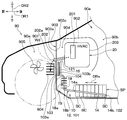
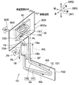
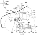
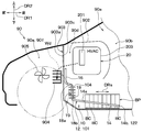
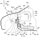
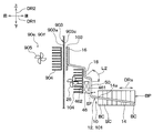
- FIG. 5 is a schematic view showing, in an enlarged manner, a vehicle front portion on which the cooling device is mounted in the vehicle of FIG. 1 in the first embodiment.
- FIG. 5 is a schematic view showing, in an enlarged manner, a vehicle front portion on which the cooling device is mounted in the vehicle of FIG. 1 in the first embodiment.
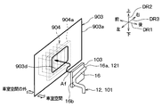
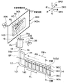
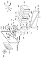
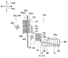
- 1st Embodiment it is the disassembled perspective view which disassembled and showed the cooling device and the apparatus of the periphery of it.
- 1st Embodiment while showing the cross section which cut
- FIG. 1st Embodiment it is the longitudinal cross-sectional view which cut
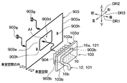
- 2nd Embodiment it is the disassembled perspective view which decomposed
- 3rd Embodiment it is the disassembled perspective view which decomposed
- FIG. 1st Embodiment it is the longitudinal cross-sectional view which cut
- 2nd Embodiment it is the disassembled perspective view which decomposed
- 3rd Embodiment it is the disassembled perspective view which decomposed
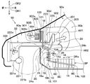
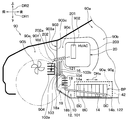
- FIG. 8 is a schematic view showing, in an enlarged manner, a front portion of the vehicle on which the cooling device is mounted in the fourth embodiment, corresponding to FIG. 2;
- FIG. 10 is a cross-sectional view showing the XX cross section of FIG. 9;
- FIG. 16 is a schematic view showing, in an enlarged manner, a front portion of the vehicle on which the cooling device is mounted in the fifth embodiment, corresponding to FIG. 9;
- 6th Embodiment it is a schematic diagram which expanded and showed the vehicle front part by which a cooling device is mounted among vehicles, Comprising: It is a figure corresponded in FIG.
- FIG. 15 is a perspective view showing a cooling device and a peripheral portion thereof in the ninth embodiment, which corresponds to FIG. 14.
- FIG. 16 is a perspective view showing a cooling device and its surrounding portion in the tenth embodiment, which is a view corresponding to FIG. 15.
- FIG. 18 is a cross-sectional view showing a XVIII-XVIII cross section of FIG. 17;
- FIG. 18 is a perspective view showing a cooling device and a peripheral portion thereof in the twelfth embodiment, which corresponds to FIG. 17;
- FIG. 15 is a perspective view showing a cooling device and a peripheral portion thereof in the thirteenth embodiment, corresponding to FIG. 14;
- FIG. 21 is a perspective view showing a cooling device and a peripheral portion thereof in the fourteenth embodiment, corresponding to FIG. 20.
- FIG. 15th Embodiment it is the schematic diagram which expanded and showed the evaporation part of a cooling device, a heating apparatus, and those periphery by the illustration method similar to FIG.
- FIG. 18 is an exploded perspective view showing the outdoor condensing portion of the cooling device and the vicinity thereof in a disassembled state according to the sixteenth embodiment, corresponding to FIG. 7.
- FIG. 40 is an exploded perspective view showing the cooling device and the peripheral devices in the eighteenth embodiment, and is a drawing corresponding to FIG.
- FIG. 19 is a schematic view showing, in an enlarged manner, a front portion of the vehicle of FIG. 1 on which the cooling device is mounted in the nineteenth embodiment, corresponding to FIG. 2.
- FIG. 21 is a schematic view showing, in an enlarged manner, a vehicle front portion on which the cooling device is mounted in the vehicle of FIG. 1 in the twentieth embodiment, which corresponds to FIG. 2.
- FIG. 21 is a schematic view showing, in an enlarged manner, a vehicle front portion on which the cooling device is mounted in the vehicle of FIG. 1 in the twenty-first embodiment, corresponding to FIG. 2.
- FIG. 19 is a schematic view showing, in an enlarged manner, a front portion of the vehicle of FIG. 1 on which the cooling device is mounted in the nineteenth embodiment, corresponding to FIG. 2.
- FIG. 21 is a schematic view showing, in an enlarged manner, a vehicle front portion on which the cooling device is mounted in the vehicle of FIG. 1 in the twentieth embodiment, which corresponds to FIG. 2.
- FIG. 21 is a schematic view showing, in an
- FIG. 23 is a schematic view showing, in an enlarged manner, a vehicle front portion on which the cooling device is mounted in the vehicle of FIG. 1 in the twenty-second embodiment, corresponding to FIG. 2.
- FIG. 32 is a schematic view showing a cooling device and devices in the vicinity of the device in the same manner as in FIG. 2 in the twenty-fourth embodiment, and corresponds to FIG. 31.
- FIG. 1 it is a schematic diagram which expanded and showed the vehicle front part by which a cooling device is mounted among vehicles, and is a figure equivalent to FIG.
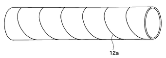
- FIG. 1 it is the figure which showed the spiral tube which is an example of the material of a tubular member.
- a battery pack BP is mounted on a vehicle 90 of the present embodiment.
- the cooling device 10 of the present embodiment is mounted on a vehicle 90 and cools the battery pack BP. That is, the target device to be cooled by the cooling device 10 is the battery pack BP.
- the vehicle 90 of the present embodiment an electric vehicle or a hybrid vehicle capable of traveling by a traveling electric motor (not shown) using the assembled battery BP as a power supply is assumed.
- Arrows DR1, DR2, and DR3 in FIGS. 1 and 3 indicate the direction of the vehicle 90 on which the cooling device 10 is mounted. That is, arrow DR1 in FIG. 1 indicates the vehicle longitudinal direction DR1, arrow DR2 indicates the vehicle vertical direction DR2, and arrow DR3 in FIG. 3 indicates the vehicle lateral direction DR3, that is, the vehicle width direction DR3.
- These directions DR1, DR2, and DR3 are directions intersecting each other, strictly speaking, directions orthogonal to each other.
- the vehicle longitudinal direction DR1 and the vehicle width direction DR3 are one directions included in the horizontal direction of the vehicle 90 (in other words, the lateral direction of the vehicle 90).
- the battery pack BP has a plurality of battery cells BC in a rectangular parallelepiped shape.
- the battery pack BP is formed of a laminate in which the plurality of battery cells BC are stacked. Specifically, the plurality of battery cells BC are stacked in a predetermined stacking direction DRs. Accordingly, the entire assembled battery BP also has a substantially rectangular parallelepiped shape.
- the battery assembly BP has a battery side surface BPb extending along the vehicle vertical direction DR2 as a part of the surface of the battery assembly BP.
- the stacking direction DRs of the battery cells BC that is, the cell stacking direction DRs may be any direction, but in the present embodiment, it coincides with the vehicle longitudinal direction DR1.
- the plurality of battery cells BC that constitute the assembled battery BP are electrically connected in series.
- Each battery cell BC constituting the assembled battery BP is constituted by a chargeable / dischargeable secondary battery (for example, a lithium ion battery, a lead storage battery).
- battery cell BC may have other shapes, such as not only a rectangular parallelepiped shape but a cylindrical shape.
- the battery pack BP may be configured to include battery cells BC electrically connected in parallel.
- the battery pack BP generates heat when power is supplied while the vehicle 90 is traveling. In addition, when the battery pack BP is left in a high temperature environment, deterioration of the battery pack BP proceeds. Therefore, it is necessary to cool by the cooling device 10.
- the cooling device 10 includes a hermetically sealed container 101, an evaporation heat diffusion plate 102, a condensation heat diffusion plate 103, and indoor fins 104.
- the cooling device 10 is configured as a thermosiphon that performs heat transfer by phase change between the liquid phase of the working fluid enclosed in the closed vessel 101 and the gas phase. Then, the cooling device 10 cools the battery pack BP by heat transfer in the thermosiphon.
- thermosiphon is a kind of heat pipe, and is used to reflux the working fluid in the liquid phase condensed in the condensation sections 16 and 18 of the closed vessel 101 to the evaporation section 14 of the closed vessel 101 using gravity. is there.
- the sealed container 101, the evaporation heat diffusion plate 102, the condensation heat diffusion plate 103, and the indoor fins 104 are all made of a material having high thermal conductivity (for example, a metal material such as an aluminum alloy).
- the passenger compartment space 90a is a space provided in the passenger compartment, and includes a seat space 90b provided with a seat 901 for a passenger and a communication space 90d connected so that air can flow to the seat space 90b.
- the cabin space 90a does not include the non-communicating space 90e in which the flow of air to the seating space 90b is blocked.
- the communication space 90d for example, a space in the instrument panel 902, a luggage room, a space in the center console, a space on the back side of a carpet laid under the foot of an occupant, and the like can be mentioned.
- the non-communicating space 90e for example, an engine room 90f and the outside of a vehicle can be mentioned. Furthermore, since the engine room 90f and the outside of the vehicle are not spaces provided in the vehicle cabin, they are not included in the vehicle cabin space 90a from this point as well.
- the closed vessel 101 is composed of a tubular member 12.
- the number of tubular members 12 constituting the closed container 101 is one.
- a material of the tubular member 12 for example, a seamless pipe is adopted.
- the tubular member 12 is formed by bending a straight pipe which is a material at a plurality of points.
- the tubular member 12 also has tube ends 121, 122 at one end and the other end of the tubular member 12, respectively.
- Each pipe end 121, 122 is hermetically closed by a brazing or sealing plug. Thereby, the closed container 101 is in the closed state.
- the working fluid is filled in the closed vessel 101, and the inside of the closed vessel 101 is filled with the working fluid.
- a refrigerant such as R134a or R1234yf used in a vapor compression refrigeration cycle is employed.
- the working fluid is filled into the closed container 101 at a predetermined filling amount.
- the predetermined filling amount is located such that the liquid surface SF of the working fluid in the liquid phase is above the evaporation portion 14 and below the indoor condensation portion 18 when the thermosiphon is not in operation with the cooling device 10 mounted on a vehicle It is considered to be a filling amount.
- the non-operating time of the thermosiphon refers to a state in which evaporation and condensation of the working fluid are not performed in the closed vessel 101.
- the thermosyphon when the thermosyphon is in operation, it means that the working fluid is being evaporated and condensed in the closed vessel 101.
- the closed container 101 includes an evaporation unit 14, an outdoor condensation unit 16 and an indoor condensation unit 18, focusing on the functional surface of the closed container 101.
- the evaporation portion 14, the outdoor condensing portion 16 and the indoor condensing portion 18 are each configured as a part of the tubular member 12.
- the evaporator 14, the outdoor condenser 16, and the indoor condenser 18 are connected in series in the order of the evaporator 14, the indoor condenser 18, and the outdoor condenser 16.
- the evaporator 14, the outdoor condenser 16 and the indoor condenser 18 are arranged in the order of the evaporator 14, the indoor condenser 18 and the outdoor condenser 16 from the lower side of the vehicle 90. Accordingly, the lower end 16 b of the outdoor condenser 16 is connected to the upper end 18 a of the indoor condenser 18, and the upper end 14 a of the evaporator 14 is connected to the lower end 18 b of the indoor condenser 18.
- the evaporating unit 14 evaporates the working fluid by absorbing heat from the battery pack BP to the working fluid in the evaporating unit 14.
- the evaporation section 14 is joined to the flat plate-shaped evaporative heat diffusion plate 102 by, for example, brazing or the like.
- a method other than brazing may be adopted for connection between the evaporation section 14 and the evaporation heat diffusion plate 102 as long as the heat conductivity between the two can be satisfactorily obtained.
- the evaporation heat diffusion plate 102 is connected to the battery side surface BPb so as to be thermally conductive on the other surface opposite to the one surface where the evaporation portion 14 is joined.
- the battery pack BP has the battery side surface BPb facing the evaporative heat diffusion plate 102, and is thermally conductively connected to the evaporative heat diffusion plate 102 as indicated by an arrow Ae.
- the evaporation unit 14 is fixed to the battery assembly BP in a thermally conductive state with respect to the battery assembly BP through the evaporative heat diffusion plate 102.
- the evaporative heat diffusion plate 102 is held pressed against the assembled battery BP so that the thermal conductivity between the evaporative heat diffusion plate 102 and the assembled battery BP is well maintained. Further, although the evaporative heat diffusion plate 102 and the assembled battery BP may be in direct contact, for example, a heat conductive sheet material or grease is sandwiched between the evaporative heat diffusion plate 102 and the assembled battery BP, so that there is a gap between them. Thermal conductivity is enhanced.
- the evaporation unit 14 is disposed so as to extend at an angle closer to the horizontal direction of the vehicle 90 at an angle closer to the horizontal direction of the vehicle 90 than the vehicle vertical direction DR2.
- the evaporation portion 14 is slightly inclined with respect to the horizontal direction of the vehicle 90 so that the upper end 14a of the evaporation portion 14 is positioned above the pipe end portion 122 to be the lower end 14b of the evaporation portion 14 It extends.
- the evaporation portion 14 extends at a slight angle with respect to the horizontal direction of the vehicle 90 so as to be positioned upward from the lower end 14b toward the upper end 14a.
- the working fluid in the vapor phase evaporated in the evaporating section 14 flows not to the lower end 14 b side but to the upper end 14 a side of the evaporating section 14 and flows from the upper end 14 a to the condensing sections 16 and 18. That is, the gas phase working fluid that has become bubbles in the evaporating section 14 easily flows out of the evaporating section 14 to the condensing sections 16 and 18, and the liquid phase working fluid returns from the condensing sections 16 and 18 to the evaporating section 14 It is easier.
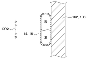
- the evaporation portion 14 Since the evaporation portion 14 is a part of the tubular member 12 and thus is tubular, it has a flat cross-sectional shape extending in the vehicle vertical direction DR2 as shown in FIG. 4 in detail. Then, one flat surface in the flat cross-sectional shape of the evaporation portion 14 is joined to the evaporation heat diffusion plate 102.
- the vehicle 90 has a vehicle body 903 surrounding a cabin space 90 a.
- the outdoor condensing portion 16 of the sealed container 101 is disposed on the side of the vehicle compartment space 90a with respect to the vehicle body 903 around the vehicle compartment space 90a.
- the outdoor condenser 16 is disposed in the passenger compartment space 90a.
- the outdoor condenser 16 is fixed to the vehicle body 903 so as to be removable from the vehicle body 903. Since the outdoor condensing portion 16 is disposed on the side of the vehicle space 90a with respect to the vehicle body 903, the outdoor condensing portion 16 can be removed from the vehicle body 903 to the side of the chamber space 90a.
- the fixed location of the vehicle body 903 to which the outdoor condenser 16 is fixed is a body panel 903a as a body constituting part that constitutes a part of the vehicle body 903 around the cabin space 90a.
- the body panel 903a is formed of a plate-like member having a vertical wall shape that separates the engine compartment 90f from the passenger compartment space 90a.
- the fact that the outdoor condenser 16 can be removed from the vehicle body 903 means that the outdoor condenser 16 is a vehicle using a detachable structure such as bolting, nuting, clipping, or snap fitting. It is to be fixed to the body 903.
- the outdoor condensing portion 16 is fixed to the vehicle body 903 by a nut stopper as described later.
- the outdoor condensing section 16 condenses the working fluid by radiating the heat from the working fluid vaporized in the evaporating section 14 to the outside air.
- the outdoor condensing portion 16 radiates heat from the working fluid in the outdoor condensing portion 16 to the outside air through the vehicle body 903.
- the outdoor condenser 16 is joined to the condensation heat diffusion plate 103 having a flat plate shape, for example, by brazing or the like. A method other than brazing may be adopted for the connection between the outdoor condensation portion 16 and the condensation heat diffusion plate 103 as long as the heat conductivity between the two can be satisfactorily obtained.
- the above-mentioned outside air is air outside the vehicle or air in a non-communicating space 90e such as an engine room 90f outside the cabin space 90a. In short, the outside air is air outside the cabin space 90a.
- Condensation heat diffusion plate 103 has one surface 103a facing body panel 903a of vehicle body 903 and the other surface 103b to which outdoor condenser 16 is joined on the opposite side to one surface 103a.
- the condensation heat diffusion plate 103 is connected to the body panel 903a in a heat conductive manner on its one surface 103a. Then, the condensation heat diffusion plate 103 is fixed in a state of being pressed against the body panel 903a by a nut stopper.
- the nut fixation of the condensation heat diffusion plate 103 with respect to the body panel 903a is performed by fastening a nut 903g fixed to the body panel 903a and screwed to a bolt 903b protruding from the body panel 903a toward the compartment space 90a.
- a nut 903g is screwed into a bolt 903b fixed to the body panel 903a from the side of the casing space 90a with respect to the body panel 903a.
- the outdoor condensing portion 16 is a surface on the indoor side which is a surface on the side of the compartment space 90 a of the vehicle body 903 so that heat can be conducted to the vehicle body 903 through the condensing heat diffusion plate 103. It is fixed to 903c.
- the outdoor condensing portion 16 can transfer heat to the outside air in the engine room 90f.
- the outdoor condensing portion 16 is a heat exchange portion which can transfer heat to the outside air by being fixed to the vehicle body 903.
- condensation heat diffusion plate 103 and the body panel 903a may be in direct contact with each other, for example, the heat conduction sheet material or grease is sandwiched between the condensation heat diffusion plate 103 and the body panel 903a, so that the space between them Thermal conductivity is enhanced.
- the vehicle 90 includes an outdoor condensing fin 904 that promotes heat radiation from the working fluid in the outdoor condensing portion 16 to the open air, and an outdoor fan 905.
- the outdoor condensation fin 904 is made of a material having high thermal conductivity (for example, a metal material such as an aluminum alloy).
- the outdoor condensing fin 904 is provided outside the cabin space 90 a so as to be exposed to the outside air, and is fixed so as to be able to conduct heat to the body panel 903 a of the vehicle body 903.
- the outdoor condensation fin 904 is joined to the body panel 903a by welding, bolting or the like.
- the outdoor condensing fin 904 is disposed at the opposite side of the condensing heat diffusion plate 103 across the body panel 903a.
- the outdoor condensation fin 904 is disposed in the engine room 90f at a place where outside air as traveling wind flows around the outdoor condensation fin 904.
- the outdoor fan 905 in FIG. 2 is a fan for blowing the outside air to the outdoor condensation fin 904, and is disposed, for example, in the engine room 90f. Therefore, even when outside air as the traveling wind is not blown to the outdoor condensation fin 904, for example, while the vehicle is stopped, the outdoor fan 905 can blow the outside air to the outdoor condensation fin 904.
- FIG. 2 components such as the outdoor condenser 16, the condensing heat diffusion plate 103, the body panel 903a, and the outdoor condensation fin 904 are not actually present for the sake of easy understanding between them. It is displayed with a gap. Moreover, illustration of the evaporative heat diffusion plate 102 is omitted. These are the same as in the following figures that adopt the same illustration method as FIG.
- the outdoor condensing part 16 is arrange
- the working fluid in the liquid phase condensed in the outdoor condenser 16 flows not to the upper end 16 a but to the lower end 16 b of the outdoor condenser 16 by the action of gravity, and flows from the lower end 16 b to the evaporator 14. That is, the working fluid such as air bubbles in the outdoor condensing part 16 ascends and easily moves to the upper end 16 a side, and the working fluid in the liquid phase in the outdoor condensing part 16 evaporates from the lower end 16 b of the outdoor condensing part 16 It is easy to leak to 14.
- the outdoor condensation part 16 has the same tubular shape as the evaporation part 14. That is, as shown in FIG. 4, the outdoor condensing part 16 has a flat cross-sectional shape extending in the vehicle vertical direction DR2. Then, one flat surface in the flat cross-sectional shape of the outdoor condensation portion 16 is joined to the condensation heat diffusion plate 103. 4 is a cross-sectional view of the evaporation portion 14 and also a cross-sectional view of the outdoor condensation portion 16 showing the IV-IV cross section of FIG.
- the vehicle 90 of the present embodiment includes an air conditioning unit 20 that performs air conditioning in the seat space 90 b.
- the air conditioning unit 20 is disposed inside the instrument panel 902.
- the air conditioning unit 20 has an evaporator 201 for cooling conditioned air, and a drain drainage portion 202 for draining drain water Wd generated by condensation on the surface of the evaporator 201.
- the drain drainage portion 202 is formed of a pipe led out of the air conditioning case 203 of the air conditioning unit 20 to the outside of the cabin space 90a (specifically, the engine room 90f).
- the discharge port 202 a of the drain drainage portion 202 is disposed in the space common to the outdoor condensing fin 904, that is, in the engine room 90 f and located above the outdoor condensing fin 904.
- the outdoor condensation fin 904 performs heat exchange not only to the outside air around the outdoor condensation fin 904 but also to the drain water Wd. That is, the outdoor condenser 16 is configured to be able to dissipate heat from the working fluid also to the drain water Wd, which is a heat radiation destination other than the outside air, through the outdoor condensation fin 904.
- the indoor condenser 18 of the sealed container 101 is disposed in the compartment space 90a, and condenses the working fluid by radiating heat from the working fluid vaporized in the evaporating unit 14 to the inside air.
- the indoor condenser 18 corresponds to another condenser that condenses the working fluid by radiating heat from the working fluid to a predetermined heat radiation destination other than the outside air.
- the predetermined heat radiation destination is internal air.
- the inside air is air in the cabin space 90a.
- An indoor fin 104 is joined to the outer peripheral surface of the indoor condensing portion 18 over the entire circumference.
- the indoor fins 104 are, for example, spine fins, and promote the heat radiation from the working fluid in the indoor condenser 18 to the inside air.
- the indoor condensing portion 18 is included in the upper and lower pipe portions 19 configured as a part of the tubular member 12.
- the upper and lower tube portions 19 are tube portions arranged to extend in the vehicle vertical direction DR2.
- the upper and lower tube portions 19 have guide portions 191 formed in a spiral shape in the upper and lower tube portions 19.
- the guide portion 191 serves to guide the working fluid of the liquid phase flowing down in the upper and lower tube portions 19.
- the guide part 191 is comprised with the helical internal fin protruded from the inner wall 192 of the up-and-down pipe part 19 to radial inside. Then, the guide portion 191 guides the working fluid of the liquid phase so that the working fluid of the liquid phase in contact with the inner wall 192 of the upper and lower tube portion 19 flows downward while swirling along the inner wall 192.
- the guide portion 191 is provided over the entire length or substantially the entire length of the upper and lower tube portions 19 in the longitudinal direction of the upper and lower tube portions 19. Accordingly, the guiding portion 191 extends to the indoor condensing portion 18 and is provided over the entire length of the indoor condensing portion 18.
- the guide part 191 of this embodiment is a component separate from the tubular member 12, and is comprised with the material which has high thermal conductivity, such as aluminum alloy.
- the gas phase working fluid that has reached the outdoor condensation part 16 dissipates heat to the outside air and condenses, and the condensed liquid phase working fluid passes through the room condensation part 18 and flows down to the evaporation part 14 by the action of gravity.
- the battery pack BP is cooled by repeating the phase change between the liquid phase and the gas phase of the working fluid in the closed vessel 101.
- the outdoor condensing portion 16 of the cooling device 10 is disposed on the side of the vehicle interior space 90 a with respect to the vehicle body 903. Then, the outdoor condensing portion 16 is fixed to the vehicle body 903, and the working fluid is condensed by causing the working fluid vaporized in the evaporation portion 14 to be released to the outside air. Therefore, while making it possible to cool the battery pack BP by the heat radiation to the outside air through the outdoor condenser portion 16, the battery pack BP is disposed on the vehicle cabin space 90a side (for example, in the vehicle cabin space 90a) with respect to the vehicle body 903. Can be realized with a simple structure.
- the outdoor condensing portion 16 is capable of transferring heat to the outside air by being fixed to the vehicle body 903. That is, it is possible to dissipate heat from the outdoor condensing portion 16 to the outside air without having to take in the outside air from the outside of the compartment space 90a separated by the vehicle body 903 to the compartment space 90a side. Therefore, while making it possible to cool the battery pack BP by the heat radiation to the outside air through the outdoor condenser portion 16, the battery pack BP is disposed on the vehicle cabin space 90a side (for example, in the vehicle cabin space 90a) with respect to the vehicle body 903. Can be realized with a simpler structure. For example, it is possible to avoid the complication of the structure of the cooling device 10 due to the waterproof structure or the like that is required along with the structure for taking in the outside air to the side of the cabin space 90a.
- both the evaporation portion 14 and the outdoor condenser 16 are on the same side as the battery body BP with respect to the vehicle body 903 It is arrange
- the outdoor condensing portion 16 dissipates the working fluid in the outdoor condensing portion 16 to the outside air via the vehicle body 903. Then, the outdoor condensing portion 16 is fixed to the indoor side body surface 903c of the vehicle body 903 so as to be able to conduct heat to the vehicle body 903, whereby the outdoor condensing portion 16 can transfer heat to the outside air. . Therefore, it is possible to utilize vehicle body 903 as a part of the heat transfer path, and to arrange outdoor condensing portion 16 on the side of cabin space 90a with respect to vehicle body 903 with a simple assembling structure.
- the vehicle 90 is provided with the outdoor condensation fin 904 that promotes the heat radiation from the working fluid in the outdoor condensation part 16 to the outside air.
- the outdoor condensing fin 904 is provided outside the cabin space 90 a so as to be exposed to the outside air, and is fixed so as to be able to conduct heat to the vehicle body 903. Therefore, it is possible to improve the condensation ability to condense the working fluid in the outdoor condensation part 16.
- the cooling device 10 includes the condensation heat diffusion plate 103 to which the outdoor condensing portion 16 is joined. Then, the outdoor condensing portion 16 is fixed to the indoor side body surface 903 c of the vehicle body 903 via the condensing heat diffusion plate 103. Therefore, it is possible to easily enlarge the heat transfer area contributing to the heat transfer between the outdoor condensing portion 16 and the vehicle body 903. Then, while preventing the heat transfer performance between the outdoor condensing portion 16 and the vehicle body 903 from being impaired, the shape of the outdoor condensing portion 16 may be a simple shape such as a simple tube shape as in the present embodiment. It is easy. Moreover, it is possible to attach the outdoor condensing part 16 to the vehicle body 903 by simple structure like the nut stopper of this embodiment.
- the evaporating unit 14 and the battery pack BP are disposed in the passenger compartment space 90a.
- the outdoor condenser 16 is fixed to the vehicle body 903 so as to be removable from the vehicle body 903. Therefore, with the cooling device 10 having a simple structure, the sealed container 101 including the outdoor condenser 16 and the evaporator 14 can be easily configured so as to be removable from the vehicle space 90a side with respect to the vehicle body 903. .
- sealed container 101 is installed in vehicle compartment space 90a together with battery assembly BP, and outdoor condenser 16 is attached to vehicle compartment space 90a relative to vehicle body 903. It is also possible to assemble from the side. Alternatively, it is also possible to assemble the outdoor condenser 16 to the vehicle body 903 from the side of the compartment space 90a at the same time as assembling the evaporation section 14 to the assembled battery BP in the compartment space 90a.
- the closed container 101 can be assembled to the vehicle body 903 in the filling state in which the closed container 101 is filled with the working fluid. Therefore, steps such as evacuation and filling of working fluid in the vehicle assembly process of cooling device 10 can be reduced, and in turn, the degree of freedom in the work sequence in vehicle assembly process of cooling device 10 can be improved. It is. In addition, it is easy to configure the sealed container 101 so as to be removable from the vehicle body 903 or the assembled battery BP in the filled state. If the sealed container 101 can be removed while being filled, it is possible to reduce the work of degassing and refilling the working fluid, for example, at the time of repair or inspection. Such a thing has the merit which can simplify the structure of the airtight container 101, even if the airtight container 101 is not comprised with the tubular member 12. FIG.
- the outdoor condensing portion 16 is configured to be able to dissipate heat from the working fluid not only to the outside air but also to the drain water Wd of the air conditioning unit 20. Therefore, even when it is difficult to dissipate heat from the outdoor condensation portion 16 to the outside air due to, for example, a high outside air temperature, it is possible to promote the heat dissipation from the outdoor condensation portion 16 by the drain water Wd. As a result, it is possible to improve the condensing efficiency and the condensing ability of the working fluid in the cooling device 10. Moreover, the condensation capability of the outdoor condensation part 16 can also be switched by switching the heat radiation whether to drain water Wd.
- the indoor blower for air cooling the indoor condensing part 18 is provided temporarily, compared with the case where the heat dissipation destination from the outdoor condensing part 16 is only the outside air, the indoor blower will be It is possible to simplify or miniaturize.
- the simplification or miniaturization of such an indoor fan leads to the noise reduction of the indoor fan, and it is possible to reduce the influence of the battery waste heat from the assembled battery BP into the passenger compartment space 90a.
- the indoor condensation portion 18 constitutes a part of the closed vessel 101, is disposed above the evaporation portion 14, and condenses the working fluid by radiating heat from the working fluid to the inside air. Therefore, it is possible to maintain the operation of the thermosiphon even in the case where the heat can not be dissipated from the outdoor condensing portion 16 to the outside air due to, for example, a high outside air temperature. As a result, it is possible to improve the condensing efficiency and the condensing ability of the working fluid in the cooling device 10.
- the closed container 101 is configured by the tubular member 12.
- the evaporation portion 14, the indoor condensation portion 18 and the outdoor condensation portion 16 are respectively configured as a part of the tubular member 12. Therefore, it is possible to establish a thermosiphon with a simple structure of the tubular member 12.
- the evaporator 14, the indoor condenser 18, and the outdoor condenser 16 are respectively configured as a part of the tubular member 12, and from the lower side, the evaporator 14, the indoor condenser 18, the outdoor condenser 16 Are arranged in the order of.
- the lower end 16 b of the outdoor condenser 16 is connected to the upper end 18 a of the indoor condenser 18, and the upper end 14 a of the evaporator 14 is connected to the lower end 18 b of the indoor condenser 18.
- the evaporator 14, the indoor condenser 18, and the outdoor condenser 16 are connected in series in the order of the evaporator 14, the indoor condenser 18, and the outdoor condenser 16 to form one tubular. It is possible to provide the member 12. From this order, the working fluid in the vapor phase evaporated in the evaporating unit 14 reaches the indoor condensing unit 18 before reaching the outdoor condensing unit 16, so that the working fluid is evaporated by the heat of the outside air when the outside air is at a high temperature It is possible to efficiently condense the working fluid in the indoor condensation section 18 by preventing the outside air heat damage.
- the working fluid evaporated by the heat of the battery pack BP condenses due to the heat radiation to the outside air.
- the outside air temperature is high, such as in summer, the working fluid evaporated by the heat of the battery pack BP condenses due to the heat radiation to the inside air cooled by the air conditioning.
- the upper and lower tube portions 19 are configured as a part of the tubular member 12 and arranged to extend in the vehicle vertical direction DR2. Then, as shown in FIG. 6, the upper and lower tube parts 19 flow the working fluid in the liquid phase so that the working fluid in the liquid phase in contact with the inner wall 192 of the upper and lower tube part 19 swirls down along the inner wall 192. It has a spiral guide 191 for guiding. That is, the guide portion 191 functions as a swirl generation unit that imparts a swirling speed component to the working fluid in the liquid phase flowing down in the upper and lower tube portions 19.
- the working fluid in the liquid phase descends along the guide portion 191 as an annular flow.
- the working fluid in the gas phase rises inside the annular flow (e.g., the center of the upper and lower tube sections 19 and its vicinity).
- the upper and lower pipe sections 19 include the indoor condensation section 18.
- the guide portions 191 of the upper and lower tube portions 19 are formed of internal fins projecting radially inward from the inner wall 192 and extend to the indoor condensation portion 18. Therefore, in addition to the function as the turning generation unit described above, it is possible to make the guide unit 191 have the function of promoting heat exchange of the working fluid in the indoor condensation unit 18. As a result, it is possible to achieve both improvement in performance of the cooling device 10 and simplification of the structure.
- the evaporation portion 14 and the outdoor condensation portion 16 corresponding to the flat tube portion of the tubular member 12 are more horizontal than the vehicle 90 in the vehicle vertical direction DR2. It is disposed to extend at an angle close to the direction with respect to the horizontal direction of the vehicle 90. And the evaporation part 14 and the outdoor condensation part 16 have a flat cross-sectional shape extended in vehicle up-down direction DR2.
- the gas-liquid separability of the working fluid is improved in the evaporator 14 and the outdoor condenser 16 respectively.
- a heat transfer area for transferring heat from the working fluid in the gas phase in the outdoor condensing portion 16 to a heat radiation destination specifically, the condensation heat diffusion plate 103
- a heat radiation destination specifically, the condensation heat diffusion plate 103
- the evaporating unit 14 is fixed to the battery pack BP in a thermally conductive state with respect to the battery pack BP via the evaporative heat diffusion plate 102. Therefore, the evaporation unit 14 can receive heat evenly from the entire battery side surface BPb of the assembled battery BP. That is, it is possible to reduce the temperature unevenness of the battery pack BP and improve the cooling performance of the cooling device 10.
- the structure of the outdoor condensing fin 904 and the periphery thereof is different from that of the first embodiment.
- the outdoor condensing fin 904 is provided outside the casing space 90a so as to be exposed to the outside air, and promotes the heat radiation from the working fluid in the outdoor condensing portion 16 to the outside air.
- the outdoor condensing fin 904 of the present embodiment is similar to the outdoor condensing fin 904 of the first embodiment.
- the outdoor condensation fin 904 of the present embodiment is joined to the one surface 103 a of the condensation heat diffusion plate 103, and is integrally configured with the condensation heat diffusion plate 103 and the outdoor condensation portion 16. That is, the cooling device 10 of the present embodiment is configured to include the outdoor condensing fin 904.
- a body through hole 903d penetrating the body panel 903a is formed in the body panel 903a.
- the body through hole 903d is formed in a size that allows the outdoor condensation fin 904 to pass through the inside of the body through hole 903d.
- the outdoor condensation fin 904 is from the side of the compartment space 90a to the body panel 903a as shown by arrow Af in FIG. It is inserted into the body through hole 903d. Therefore, with the outdoor condensation fin 904 exposed through the body through hole 903d to the outside of the compartment space 90a, the condensation heat diffusion plate 103 is configured to close the body through hole 903d from the compartment space 90a side. It is fixed against. Thus, the outdoor condensing portion 16 can transfer heat to the outside air through the outdoor condensing fin 904.
- one surface 103 a of the condensation heat diffusion plate 103 has a fin peripheral portion 103 d positioned so as to surround the portion to which the outdoor condensation fin 904 is joined.
- the fin peripheral portion 103 d is pressed against a body hole peripheral portion 903 e of the vehicle body 903 which constitutes the periphery of the body through hole 903 d.
- the fin peripheral portion 103d seals between the body hole peripheral portion 903e and the fin peripheral portion 103d.
- a waterproof sealing material is provided between the fin peripheral portion 103d and the body hole peripheral portion 903e.
- the condensation heat diffusion plate 103 can prevent the water from entering the casing space 90a from the body through hole 903d. And while constructing such a waterproof structure, it is possible to arrange the outdoor condensation part 16 in the casing space 90a side with respect to the vehicle body 903 by a simple assembling structure.
- the present embodiment is the same as the first embodiment except for the above description. And in this embodiment, the effect show
- the structure of the outdoor condensation fin 904 and the periphery thereof is different from that of the first embodiment.
- a body through hole 903d penetrating the body panel 903a is formed in the body panel 903a of the present embodiment.
- the outdoor condensing fin 904 is provided outside the casing space 90 a so as to be exposed to the outside air, and promotes the heat radiation from the working fluid in the outdoor condensing portion 16 to the outside air.
- the outdoor condensing fin 904 of the present embodiment is similar to the outdoor condensing fin 904 of the first embodiment.
- the outdoor condensation fin 904 of the present embodiment has a flat plate-like substrate portion 904a along the body panel 903a, and the substrate portion 904a is joined to the body panel 903a.
- the substrate portion 904a is fixed to the body panel 903a so as to close the body through hole 903d from the side opposite to the side of the cabin space 90a (that is, the side of the engine room 90f).
- the joint portion between the substrate portion 904a and the body panel 903a surrounds the entire body through hole 903d and is waterproofed by, for example, sandwiching a sealing material for welding or waterproofing.
- the outdoor condensing portion 16 is fixed on the side of the casing space 90 a of the outdoor condensation fin 904 via the inside of the body through hole 903 d so as to be able to conduct heat to the outdoor condensation fin 904.
- the condensation heat diffusion plate 103 to which the outdoor condensation portion 16 is joined is fixed to the substrate portion 904 a of the outdoor condensation fin 904 through the inside of the body through hole 903 d so that heat can be conducted to the outdoor condensation fin 904. It is done.
- the outdoor condensing portion 16 can transfer heat to the outside air through the outdoor condensing fin 904.
- condensation heat diffusion plate 103 may be in direct contact with the substrate portion 904 a of the outdoor condensation fin 904, for example, a heat conduction sheet material or grease is sandwiched between the condensation heat diffusion plate 103 and the substrate portion 904 a. Thermal conductivity between the two is enhanced.
- the present embodiment is the same as the first embodiment except for the above description. And in this embodiment, the effect show
- the substrate portion 904a of the outdoor condensation fin 904 is fixed to the body panel 903a so as to close the body through hole 903d from the side opposite to the cabin space 90a. Therefore, although the body through hole 903d is provided in the present embodiment, the outdoor condensation fin 904 can prevent the entry of water from the body through hole 903d into the compartment space 90a.
- the outdoor condensing portion 16 is fixed to the side of the compartment space 90a of the outdoor condensing fin 904 via the inside of the body through hole 903d so that heat can be conducted to the outdoor condensing fin 904. There is.
- the outdoor condensing portion 16 can transfer heat to the outside air through the outdoor condensing fin 904. Therefore, it is possible to arrange the outdoor condenser 16 on the side of the passenger compartment space 90a with respect to the vehicle body 903 with a simple assembling structure.
- the cooling device 10 is a part of the closed container 101 in addition to the outdoor condensing portion 16 and the indoor condensing portion 18, and is disposed above the evaporation portion 14.
- the refrigerant pipe condenser 24 is provided.
- the present embodiment is different from the first embodiment in this point.
- a vapor compression type refrigeration cycle circuit 22 in which a refrigerant circulates is used.
- the refrigeration cycle circuit 22 includes a compressor 221, an outdoor condenser 222 disposed in front of the engine room 90f, an expansion valve 223, an evaporator 201, and pipes connecting them.
- Arrows AR1 and AR2 in FIG. 9 indicate the conditioned air blown out by the air conditioning unit 20.
- the compressor 221 compresses the refrigerant and then discharges it.
- the refrigerant discharged from the discharge port 221a of the compressor 221 is sucked into the suction port 221b of the compressor 221 through the outdoor condenser 222, the expansion valve 223, and the evaporator 201 in this order.
- the refrigerant is dissipated from the refrigerant to the traveling air which is the outside air in the outdoor condenser 222. Outside air may be forcibly blown to the outdoor condenser 222 by the outdoor blower 222 a in the engine room 90 f.
- the expansion valve 223 the refrigerant is decompressed and expanded.
- the air flowing through the air conditioning unit 20 and the refrigerant exchange heat the air is cooled, and the refrigerant evaporates.
- the refrigerant pipe condensing part 24 of this embodiment is arrange
- the refrigerant pipe condenser 24 is a part of the tubular member 12.
- the evaporator 14, the outdoor condenser 16, the indoor condenser 18, and the refrigerant pipe condenser 24 are connected in series in the order of the evaporator 14, the indoor condenser 18, the outdoor condenser 16, and the refrigerant pipe condenser 24. .
- the evaporating unit 14, the outdoor condensing unit 16, the indoor condensing unit 18 and the refrigerant pipe condensing unit 24 are arranged in the evaporation unit 14, the indoor condensing unit 18, the outdoor condensing unit 16 and the refrigerant pipe condensing unit 24 from below the vehicle 90.
- the lower end 16 b of the outdoor condenser 16 is connected to the upper end 18 a of the indoor condenser 18, and the upper end 14 a of the evaporator 14 is connected to the lower end 18 b of the indoor condenser 18.
- the upper end 16 a of the outdoor condenser 16 is connected to the lower end 24 b of the refrigerant pipe condenser 24.
- the refrigerant pipe condensing unit 24 is connected to the predetermined heat absorbing unit 225 included in the refrigeration cycle circuit 22 so as to be thermally conductive.
- the refrigerant pipe condensing unit 24 and the predetermined heat absorbing unit 225 constitute the heat exchanger 25 that exchanges heat between the refrigerant and the working fluid.
- the predetermined heat absorption part 225 has a tubular shape, and is a part of a piping member connecting the evaporator 201 and the suction port 221 b of the compressor 221 in the refrigeration cycle circuit 22.
- the refrigerant pipe condensing unit 24 is disposed below the predetermined heat absorbing unit 225. At the same time, the refrigerant pipe condensing portion 24 is fixed by the clip 241 so as to be pressed against the predetermined heat absorbing portion 225 so as to be able to conduct heat.
- the refrigerant pipe condensing part 24 Since the method of fixing the refrigerant pipe condensing part 24 to the predetermined heat absorbing part 225 is such clip stopping by the clip 241, the refrigerant pipe condensing part 24 is attachable to and detachable from the predetermined heat absorbing part 225.
- prescribed heat absorption part 225 may contact directly, for example, a heat conduction sheet material or grease is pinched
- the refrigerant pipe condenser 24 Since the refrigerant pipe condensing part 24 is fixed in this manner, the refrigerant flowing in the predetermined heat absorbing part 225 of the refrigeration cycle circuit 22 is dissipated from the working fluid vaporized in the evaporating part 14. Thus, the refrigerant pipe condenser 24 condenses the working fluid. Therefore, the refrigerant pipe condenser 24 corresponds to another condenser that condenses the working fluid by radiating heat from the working fluid to a predetermined heat radiation destination other than the outside air. In the case of the refrigerant pipe condensing portion 24, the predetermined heat radiation destination is the refrigerant flowing in the predetermined heat absorbing portion 225. As described above, in the present embodiment, in addition to the indoor condenser 18, the refrigerant pipe condenser 24 also corresponds to the other condenser, and the hermetic container 101 has a plurality of other condensers.
- the refrigerant pipe condensing part 24 is arrange
- the flow of the working fluid in the gas phase and the liquid phase in the refrigerant pipe condenser 24 becomes the same as in the outdoor condenser 16 described above due to the inclination of the refrigerant pipe condenser 24.
- the refrigerant pipe condensation part 24 is fixed along the predetermined heat absorption part 225 of the refrigeration cycle circuit 22, the predetermined heat absorption part 225 is also held in the inclined posture like the refrigerant pipe condensation part 24.
- an indoor fan 26 for air cooling the indoor condensing portion 18 is provided.
- the indoor blower 26 operates appropriately to blow the inside air to the indoor fins 104 and the indoor condensing portion 18.
- the present embodiment is the same as the first embodiment except for the above description. And in this embodiment, the effect show
- the refrigerant pipe condensing portion 24 is disposed below the predetermined heat absorbing portion 225 of the refrigeration cycle circuit 22 and is fixed so as to be able to conduct heat to the predetermined heat absorbing portion 225 There is. Then, since the liquid refrigerant and the oil flow mostly downward in the predetermined heat absorbing portion 225, the working fluid in the refrigerant pipe condensing portion 24 can easily dissipate the heat to the liquid refrigerant and the oil. Further, in the refrigerant pipe condensing part 24, the working fluid in the gas phase tends to be biased toward the predetermined heat absorbing part 225 located above than the working fluid in the liquid phase. From such a thing, it is possible to enlarge the condensation performance of refrigerant piping condensation part 24 preferentially using the lower part which is a part which is easy to absorb heat among predetermined heat absorption parts 225.
- this embodiment is a modification based on the first embodiment, it is also possible to combine this embodiment with the above-described second embodiment or third embodiment.
- the refrigerant pipe condenser 24 and the predetermined heat absorbing part 225 of the refrigeration cycle circuit 22 are disposed in an engine room 90f which is outside the cabin space 90a.
- a body through hole 903f is formed in the vehicle body 903 in order to arrange the refrigerant pipe condensing portion 24 in the engine room 90f.
- the present embodiment is different from the fourth embodiment in this point.
- prescribed heat absorption part 225 is clip stop by the clip 241 similarly to 4th Embodiment.
- a part of the sealed container 101 extends out of the passenger compartment space 90a. That is, focusing on the arrangement place in the vehicle 90, the sealed container 101 has the indoor arrangement part 28 arranged in the compartment space 90a and the outdoor arrangement part 30 disposed outside the compartment space 90a. There is.
- the evaporating unit 14, the outdoor condensing unit 16, and the indoor condensing unit 18 are included in the indoor arrangement unit 28.
- the refrigerant pipe condensing unit 24 is included in the outdoor arrangement unit 30.
- the outdoor placement portion 30 is disposed outside the cabin space 90a in a state of being led out of the cabin space 90a through the body through hole 903f. Furthermore, the body through hole 903f is formed in a size that allows the outdoor arrangement portion 30 to pass through the inside of the body through hole 903f.
- the outdoor placement portion 30 when the outdoor placement portion 30 is removed from the predetermined heat absorption portion 225, the outdoor placement portion 30 can be taken from the outside of the vehicle compartment space 90a to the vehicle compartment space 90a side through the body through hole 903f. Therefore, the entire sealed container 101 including the outdoor arrangement portion 30 can be easily configured so as to be removable to the side of the compartment space 90 a with respect to the vehicle body 903.
- the periphery of the tubular member 12 is sealed by, for example, a seal grommet.
- the present embodiment is the same as the fourth embodiment except for the points described above. And in this embodiment, the effect show
- the arrangement of the outdoor condenser 16 and the refrigerant pipe condenser 24 in the sealed container 101 is different from that of the fourth embodiment.
- prescribed heat absorption part 225 is clip stop by the clip 241 similarly to 4th Embodiment.
- the evaporator 14, the outdoor condenser 16, the indoor condenser 18, and the refrigerant pipe condenser 24 are connected in series in the order of the evaporator 14, the indoor condenser 18, the refrigerant pipe condenser 24, and the outdoor condenser 16. ing.
- the evaporating unit 14, the outdoor condensing unit 16, the indoor condensing unit 18 and the refrigerant pipe condensing unit 24 are arranged in the evaporation unit 14, the indoor condensing unit 18, the refrigerant pipe condensing unit 24 and the outdoor condensing unit 16 from the lower side of the vehicle 90 Arranged in order.
- the lower end 16 b of the outdoor condenser 16 is connected to the upper end 24 a of the refrigerant pipe condenser 24, and the lower end 24 b of the refrigerant pipe condenser 24 is connected to the upper end 18 a of the indoor condenser 18. Further, the lower end 18 b of the indoor condenser 18 is connected to the upper end 14 a of the evaporator 14.
- the present embodiment is the same as the fourth embodiment except for the points described above. And in this embodiment, the effect show
- a heat generating device 91 different from the battery pack BP is provided in the passenger compartment space 90 a.
- the cooling device 10 further includes a second evaporation unit 32 for cooling the heat generating device 91, in addition to the above-described evaporation unit 14 as a first evaporation unit connected to the battery pack BP.
- the present embodiment is different from the first embodiment in these points.
- the second evaporating unit 32 is provided between the first evaporating unit 14 and the indoor condensing unit 18, and the arrangement of the outdoor condensing unit 16 is the same as that of the first embodiment.
- the second evaporation portion 32 constitutes a part of the tubular member 12 and is disposed in the cabin space 90a.
- the first evaporator 14, the second evaporator 32, the outdoor condenser 16, and the indoor condenser 18 are connected in series in the order of the first evaporator 14, the second evaporator 32, the indoor condenser 18, and the outdoor condenser 16. It is connected.
- the first evaporator 14, the second evaporator 32, the outdoor condenser 16, and the indoor condenser 18 are the first evaporator 14, the second evaporator 32, the indoor condenser 18, and the outdoor from the lower side of the vehicle 90.
- the condensers 16 are arranged in order.
- the lower end 16 b of the outdoor condenser 16 is connected to the upper end 18 a of the indoor condenser 18, and the lower end 18 b of the indoor condenser 18 is connected to the upper end 32 a of the second evaporator 32.
- the lower end 32 b of the second evaporation unit 32 is connected to the upper end 14 a of the evaporation unit 14.
- the second evaporation unit 32 is connected to the heat generating device 91 so as to be thermally conductive.
- the heat generating apparatus 91 is an electric component that generates heat, and is, for example, a relay, an ECU, a charger, a DCDC converter, or the like.
- the heat generating device 91 is a device that is allowed to have a temperature higher than that of the battery pack BP. For example, during heat generation of the heat generating device 91, the temperature becomes higher than that of the battery pack BP.
- the second evaporating unit 32 and the heat generating device 91 may be in direct contact with each other, for example, a heat conductive sheet material or grease is sandwiched between the second evaporating unit 32 and the heat generating device 91, so that the two are separated. Thermal conductivity is enhanced.
- the second evaporation unit 32 evaporates the working fluid by causing the working fluid in the second evaporation unit 32 to absorb heat from the heating device 91. Further, the second evaporation unit 32 is disposed below the liquid surface SF of the working fluid formed in the closed container 101 when the thermosiphon is not operating and above the first evaporation unit 14.
- the working fluid in the liquid phase can easily absorb the heat of the heat generating device 91, and the working fluid can be well evaporated. Then, the air bubbles generated in the second evaporating unit 32 by the heat of the heat generating device 91 can be made to flow out to the indoor condensing unit 18 instead of the first evaporating unit 14. That is, air bubbles generated by the heat of the heat generating device 91 can be prevented from being dissipated to the assembled battery BP.
- the present embodiment is the same as the first embodiment except for the above description. And in this embodiment, the effect show
- the present embodiment is a modification based on the first embodiment, it is also possible to combine this embodiment with any of the second to sixth embodiments described above.
- the cooling device 10 of the present embodiment has two closed containers 101. And the two airtight containers 101 are respectively comprised by the mutually different tubular member 12. As shown in FIG. That is, the cooling device 10 has a plurality of tubular members 12 which are single pipes. The present embodiment is different from the first embodiment in this point.
- FIG. 14 shows the liquid level SF of the working fluid when the thermosiphon is not operating.
- the method of fixing the condensation heat diffusion plate 103 to the body panel 903a is the same nut stop as in the first embodiment, but in FIG. 14, illustration of the bolt 903b (see FIG. 3) and the like is omitted.
- one of the two closed containers 101 is a first evaporation pipe section 141 included in the evaporation section 14 and an outdoor condensation section disposed above the first evaporation pipe section 141. It has 16 and.
- the first evaporation tube portion 141 and the outdoor condensation portion 16 are connected in series to each other, and are included in one tubular member 12 constituting one closed container 101. Therefore, in one closed container 101, the working fluid in the vapor phase evaporated in the first evaporation pipe portion 141 is raised by the heat of the battery pack BP and flows to the outdoor condensation portion 16. At the same time, the working fluid in the liquid phase condensed in the outdoor condenser 16 flows down and flows to the first evaporation pipe 141.
- the other closed vessel 101 of the two closed vessels 101 includes a second evaporation pipe portion 142 included in the evaporation portion 14, and an indoor condensation portion 18 disposed above the second evaporation pipe portion 142.
- the second evaporation pipe portion 142 and the indoor condensation portion 18 are connected in series to each other, and are included in the other tubular member 12 constituting the other closed vessel 101. Therefore, in the other closed vessel 101, the working fluid in the vapor phase evaporated in the second evaporation pipe 142 due to the heat of the battery pack BP rises and flows to the indoor condenser 18. At the same time, the liquid working fluid condensed in the indoor condenser 18 flows down and flows to the second evaporation pipe 142.
- the first evaporation pipe portion 141 and the second evaporation pipe portion 142 are arranged to extend in an inclined manner with respect to the horizontal direction of the vehicle 90, similarly to the evaporation portion 14 of the first embodiment.
- the present embodiment is the same as the first embodiment except for the above description. And in this embodiment, the effect show
- the outdoor condensing portion 16 and the indoor condensing portion 18 are respectively connected to the evaporation pipe portions 141 and 142 different from each other, the outdoor condensing portion 16 and the indoor condensing portion 18 are separated. It is easy to arrange. That is, it is possible to improve the mounting freedom of the outdoor condenser 16 and the indoor condenser 18.
- the ninth embodiment Next, a ninth embodiment will be described. In the present embodiment, differences from the above-described eighth embodiment will be mainly described.
- the closed container 101 of the present embodiment is configured of a looped tubular member 12.
- the present embodiment is different from the eighth embodiment in this point.
- the evaporation unit 14 has a first evaporation pipe 141 and a second evaporation pipe 142.
- the outdoor condensing portion 16 has a first outdoor condensing pipe portion 161 and a second outdoor condensing pipe portion 162.
- the indoor condensing portion 18 has a first indoor condensing pipe portion 181 and a second indoor condensing pipe portion 182.
- the first evaporation pipe part 141, the first indoor condenser pipe part 181 and the first outdoor condenser pipe part 161 are connected in series, and from the lower side of the vehicle 90, the first evaporation pipe part 141, the first indoor condenser pipe part 181, the first They are disposed in the order of the 1 outdoor condenser tube portion 161.
- the working fluid in the vapor phase evaporated in the first evaporation pipe portion 141 rises due to the heat of the battery pack BP and flows to the first indoor condensation pipe portion 181 and remains without being condensed in the first indoor condensation pipe portion 181
- the gas-phase working fluid flows from the first indoor condenser pipe portion 181 to the first outdoor condenser pipe portion 161.
- the working fluid in the liquid phase condensed in the first outdoor condenser tube portion 161 flows down and flows to the first evaporation tube portion 141.
- the working fluid of the liquid phase condensed in the first indoor condensation pipe portion 181 also flows down and flows to the first evaporation pipe portion 141.
- the second evaporation pipe 142, the second indoor condenser pipe 182, and the second outdoor condenser pipe 162 are connected in series, and from the lower side of the vehicle 90, the second evaporation pipe 142, the second indoor condenser pipe 182 , And the second outdoor condenser tube portion 162 are arranged in order.
- the working fluid of the vapor phase evaporated in the second evaporation pipe 142 rises due to the heat of the battery pack BP and flows to the second indoor condenser pipe 182 and remains uncondensed in the second indoor condenser pipe 182
- the gas-phase working fluid flows from the second indoor condenser tube 182 to the second outdoor condenser tube 162.
- the working fluid in the liquid phase condensed in the second outdoor condenser tube portion 162 flows down and flows to the second evaporation tube portion 142.
- the working fluid of the liquid phase condensed in the second indoor condensation pipe portion 182 also flows down and flows to the second evaporation pipe portion 142.
- tubular member 12 is loop-shaped, the lower end of the first evaporation pipe portion 141 and the lower end of the second evaporation pipe portion 142 are connected to each other, and the upper end of the first outdoor condenser pipe portion 161 and the second outdoor The upper end of the condensing tube portion 162 is connected to each other.
- the first evaporation pipe portion 141 and the second evaporation pipe portion 142 are arranged to extend in an inclined manner with respect to the horizontal direction of the vehicle 90, similarly to the evaporation portion 14 of the first embodiment. Further, the first outdoor condenser pipe portion 161 and the second outdoor condenser pipe portion 162 are disposed to extend in a slanted manner with respect to the horizontal direction of the vehicle 90, similarly to the outdoor condenser portion 16 of the first embodiment.
- the present embodiment is the same as the eighth embodiment except as described above. And in this embodiment, the effect show
- the internal pressure of the first outdoor condensation pipe portion 161 and the second outdoor condensation pipe portion 162 becomes equal. This makes it possible to stabilize the fluid level SF of the working fluid during operation of the thermosyphon.
- the closed container 101 of the present embodiment is the same as the ninth embodiment in that it is constituted by the looped tubular member 12.
- the cooling device 10 of the present embodiment is configured as a loop thermosiphon in which the working fluid circulates in an annular manner.
- the indoor condensation part 18 is one place.
- the present embodiment differs from the ninth embodiment in these points.
- the first evaporation pipe portion 141 and the second evaporation pipe portion 142 are disposed so as to extend obliquely with respect to the horizontal direction of the vehicle 90.
- the second evaporation pipe 142 is disposed above the first evaporation pipe 141, and the upper end of the first evaporation pipe 141 is the second evaporation pipe.
- the lower end of the portion 142 is connected. Therefore, the first evaporation pipe portion 141 and the second evaporation pipe portion 142 connected in series to each other constitute a V-shaped pipe portion. Therefore, both the working fluid evaporated in the first evaporation pipe section 141 and the working fluid evaporated in the second evaporation pipe section 142 flow out from the upper end of the second evaporation pipe section 142.
- first outdoor condensing pipe portion 161 and the second outdoor condensing pipe portion 162 are disposed so as to extend obliquely with respect to the horizontal direction of the vehicle 90.
- the 2nd outdoor condensing pipe part 162 is arrange
- the upper end of the second evaporation pipe portion 142 is connected to the upper end of the first outdoor condensing pipe portion 161.
- the lower end of the second outdoor condenser pipe portion 162 is connected to the upper end 18 a of the indoor condenser portion 18, and the lower end 18 b of the indoor condenser portion 18 is connected to the lower end of the first evaporation pipe portion 141.
- the first evaporation pipe portion 141, the second evaporation pipe portion 142, the first outdoor condensation pipe portion 161, the second outdoor condensation pipe portion 162, and the indoor condensation portion 18 are annularly connected in the order described. There is. Therefore, the working fluid in the gas phase evaporated in the first evaporation pipe portion 141 and the second evaporation pipe portion 142 rises, and flows to the first outdoor condensation pipe portion 161.
- the gas phase working fluid that has flowed into the first outdoor condensing pipe 161 is condensed by the first outdoor condensing pipe 161, the second outdoor condensing pipe 162, and the indoor condensing part 18, and the condensed working fluid flows down.
- the lower end of the first evaporation pipe portion 141 returns to the first evaporation pipe portion 141.
- the present embodiment is the same as the ninth embodiment except as described above. And in this embodiment, the effect show
- the configuration of the evaporation unit 14 is different from that of the first embodiment. Further, in the present embodiment, two battery packs BP are provided.
- the cooling device 10 of the present embodiment does not include the evaporative heat diffusion plate 102.
- the sealed container 101 of the present embodiment includes the first tubular member 12, the second tubular member 34, and the plurality of evaporation tubes 143.
- the evaporation portion 14 has a lower flow passage portion 144 included in the first tubular member 12, an upper flow passage portion 145 included in the second tubular member 34, and a plurality of evaporation tubes 143.
- the first tubular member 12 has, in addition to the lower flow passage portion 144 of the evaporation portion 14, an upper and lower pipe portion 19 including the indoor condensation portion 18 and an outdoor condensation portion 16.
- the plurality of evaporation tubes 143 extend in the vehicle vertical direction DR2 and are arranged side by side in the cell stacking direction DRs.
- Each of the plurality of evaporation tubes 143 has a flat cross-sectional shape whose longitudinal direction is the cell stacking direction DRs.
- the battery pack BP is connected to the flat surfaces 143a and 143b on both sides of the evaporation tube 143 in a state where the battery side surface BPb is pressed through the heat conduction sheet material 35. Thereby, the battery pack BP is fixed to the plurality of evaporation tubes 143 of the evaporation unit 14 so as to be capable of conducting heat.
- lower ends 143c of the plurality of evaporation tubes 143 are respectively connected to the lower flow passage portion 144, and the evaporation tubes 143 communicate with the lower flow passage portion 144 at the lower ends 143c.
- upper ends 143 d of the plurality of evaporation tubes 143 are respectively connected to the upper flow passage portion 145, and the evaporation tubes 143 are in communication with the upper flow passage portion 145 at the upper ends 143 d.
- the lower flow passage portion 144 is formed to extend in the cell stacking direction DRs, and is connected to the lower end 18b of the indoor condensing portion 18 at one of the cell stacking direction DRs.
- the lower flow passage portion 144 is located below the battery assembly BP and the plurality of evaporation tubes 143, and is disposed at an interval from the battery assembly BP and the heat conduction sheet material 35.
- the upper flow passage portion 145 is formed to extend in the cell stacking direction DRs, and is located above the lower flow passage portion 144, the battery assembly BP, and the plurality of evaporation tubes 143. Further, the upper flow passage portion 145 is connected to a portion of the upper and lower pipe portions 19 below the indoor condensation portion 18 in one of the cell stacking directions DRs.
- the second tubular member 34 including the upper channel portion 145 is connected to the upper and lower tube portions 19 from the side of the upper and lower tube portions 19. Thus, the upper channel portion 145 is in communication with the upper and lower pipe portions 19.
- the working fluid in the liquid phase in the evaporation tube 143 is the battery assembly BP Evaporates due to the heat of As a result, the battery pack BP is deprived of heat and cooled.
- the gas phase working fluid evaporated in the evaporation pipe 143 rises and flows into the upper channel portion 145 and flows from the upper channel portion 145 to the indoor condensing portion 18 of the first tubular member 12.
- the flow of the working fluid between the indoor condenser 18 and the outdoor condenser 16 is the same as in the first embodiment.
- the filling amount of the working fluid is previously adjusted so that the working fluid in the liquid phase enters the evaporation pipe 143, for example, during non-operation and during operation of the thermosiphon.
- the working fluid in the liquid phase flowing down from the indoor condensation portion 18 flows into the lower flow path portion 144 of the evaporation portion 14.
- the working fluid in the liquid phase which flows down hardly enters the second tubular member 34.
- the working fluid in the liquid phase that has flowed into the lower flow path portion 144 is distributed from the lower flow path portion 144 to each of the plurality of evaporation pipes 143.
- the battery pack BP is cooled by repeating the phase change between the liquid phase and the gas phase of the working fluid in the closed vessel 101.
- the working fluid in the gas phase and the flow of the working fluid in the liquid phase are separated as described above, the working fluid can flow smoothly in the evaporation unit 14. As a result, the cooling capacity of the cooling device 10 can be improved.
- the present embodiment is the same as the first embodiment except for the above description. And in this embodiment, the effect show
- the present embodiment is a modification based on the first embodiment, it is also possible to combine this embodiment with any of the above second to seventh embodiments.
- the closed vessel 101 has a tubular member 12 extending in a U-shape and a plurality of evaporation tubes 143.
- the lower channel portion 144 and the upper channel portion 145 of the evaporation portion 14 are included in the tubular member 12.
- FIG. 18 described above is a cross-sectional view showing the XVIII-XVIII cross section of FIG. 17, but also shows the XVIII-XVIII cross section of FIG.
- the configuration of the evaporation unit 14 is the same as that of the eleventh embodiment, and the configuration of the outdoor condensing unit 16 is the same as that of the tenth embodiment.
- the lower flow passage portion 144 of the present embodiment is connected to the lower end 18 b of the indoor condensation portion 18 as in the eleventh embodiment.
- the upper flow passage portion 145 is connected to the upper end of the first outdoor condenser tube portion 161.
- the working fluid in the vapor phase evaporated in the evaporation pipe 143 rises and flows into the upper flow path portion 145, and flows from the upper flow path portion 145 to the first outdoor condensation pipe portion 161.
- the working fluid in the liquid phase flowing down from the indoor condensation portion 18 flows into the lower flow path portion 144 of the evaporation portion 14.
- the flow of the working fluid in the evaporator 14 is the same as in the eleventh embodiment, and the flow of the working fluid from the outdoor condenser 16 to the indoor condenser 18 is the same as that in the tenth embodiment.
- the present embodiment is the same as the tenth embodiment or the eleventh embodiment except for what has been described above. And in this embodiment, the effect show
- the closed vessel 101 of the present embodiment is constituted by a looped tubular member 12.
- the present embodiment is different from the eighth embodiment in this point.
- the lower end of the first evaporation pipe portion 141 and the lower end of the second evaporation pipe portion 142 are connected to each other.
- the upper end 16a of the outdoor condensing part 16 and the upper end 18a of the indoor condensing part 18 are mutually connected.
- the tubular member 12 is formed in a loop shape.
- the indoor condensing portion 18 is supported in an inclined attitude as in the case of the outdoor condensing portion 16 and is not included in the upper and lower pipe portions 19. And the indoor condensation part 18 is arrange
- the overall height occupied by cooling device 10 in vehicle vertical direction DR2 may be reduced compared to the case where a plurality of condensing portions are arranged side by side in vehicle vertical direction DR2. It is possible.
- the present embodiment is the same as the eighth embodiment except as described above. And in this embodiment, the effect show
- the looped tubular member 12 constituting the closed vessel 101 of the present embodiment has a refrigerant pipe condensing part 24 in place of the indoor condensing part 18.
- the present embodiment differs from the thirteenth embodiment.
- the fixing method of the outdoor condensation fin 904 and the condensation heat-diffusion board 103 with respect to the body panel 903a is the same as that of 2nd Embodiment shown by FIG.
- the lower end of the first evaporation pipe portion 141 and the lower end of the second evaporation pipe portion 142 are connected to each other.
- the upper end 24 a of the refrigerant pipe condensing portion 24 and the upper end 16 a of the outdoor condensing portion 16 are connected to each other.
- the tubular member 12 is formed in a loop shape.
- the refrigerant pipe condenser 24 of the present embodiment is the same as the refrigerant pipe condenser 24 of the fourth to sixth embodiments described above. Therefore, the refrigerant pipe condensing part 24 of this embodiment is being fixed to the predetermined
- the predetermined heat absorption portion 225 of the present embodiment is, for example, a part of a piping member connecting the evaporator 201 and the suction port 221 b of the compressor 221 in the refrigeration cycle circuit 22 of FIG. 9 as in the fourth embodiment described above. is there.
- the refrigerant pipe condenser 24 is disposed outside the passenger compartment space 90a. That is, the refrigerant pipe condensing part 24 is included in the outdoor arrangement part 30.
- the outdoor placement portion 30 is disposed outside the cabin space 90a in a state of being led out of the cabin space 90a through the body through hole 903d.
- the body through hole 903d is formed in a size that allows the outdoor arrangement portion 30 to pass through the inside of the body through hole 903d.
- refrigerant pipe condensing portion 24 is supported in an inclined attitude as in the case of the outdoor condensing portion 16. Then, refrigerant pipe condensing portion 24 is disposed at the same height as outdoor condensing portion 16 in the vehicle vertical direction DR2.
- the outdoor condensing portion 16 is disposed above the second evaporation pipe portion 142, and the lower end 16 b of the outdoor condensing portion 16 is connected to the upper end of the second evaporation pipe portion 142. Therefore, the working fluid of the gas phase evaporated in the second evaporation pipe portion 142 rises and flows to the outdoor condensing portion 16. Then, the working fluid in the liquid phase condensed in the outdoor condenser 16 flows down and flows to the second evaporation pipe 142.
- the refrigerant pipe condenser 24 is disposed above the first evaporation pipe 141, and the lower end 24 b of the refrigerant pipe condenser 24 is connected to the upper end of the first evaporation pipe 141. Accordingly, the working fluid in the gas phase evaporated in the first evaporation pipe portion 141 rises and flows to the refrigerant pipe condensation portion 24. Then, the working fluid in the liquid phase condensed in the refrigerant pipe condenser 24 flows down to the first evaporation pipe 141.
- the present embodiment is the same as the thirteenth embodiment except as described above. Further, in the present embodiment, the same effects as those of the thirteenth embodiment can be obtained from the configuration common to the thirteenth embodiment.
- the cooling device 10 of the present embodiment also has a function of warming up the battery pack BP.
- the cooling device 10 is provided with a heating heat exchange section 38 which constitutes a part of the tubular member 12 and a heating apparatus 40 thermally coupled to the heating heat exchange section 38.
- the present embodiment is different from the first embodiment in this point.
- the heating heat exchange unit 38 and the heating device 40 are disposed, for example, in the passenger compartment space 90a.
- the heating heat exchange unit 38 is disposed below the evaporation unit 14.
- the lower tube end 122 of the tubular member 12 is the lower end of the heating heat exchange unit 38, and the heating heat exchange unit 38 is connected to the lower end 14 b of the evaporation unit 14. That is, the heating heat exchange unit 38 is connected in series to the evaporation unit 14. Therefore, in the heating heat exchange unit 38, a working fluid in a liquid phase is present both when the thermosiphon is activated and when it is not activated.
- heating device 40 is an electric heater in which operation and non-operation of heating device 40 are appropriately switched according to the temperature of battery assembly BP. For example, when the temperature of the battery pack BP is lower than a predetermined temperature threshold value, it is determined by the electronic control device or the like that warm-up is necessary, and the heating device 40 generates heat.
- the heating device 40 When the heating device 40 generates heat, the working fluid in the liquid phase in the heating heat exchange unit 38 is evaporated by the heating device 40 and flows as bubbles into the evaporation unit 14. Then, the assembled battery BP is heated and warmed up by the working fluid of the gas phase, which is, for example, air bubbles in the evaporation portion 14. At the same time, the gas phase working fluid condenses to become a liquid phase working fluid and returns from the evaporation unit 14 to the heating heat exchange unit 38. Thus, the warm-up of the battery pack BP is performed.
- the present embodiment is the same as the first embodiment except for the above description. And in this embodiment, the effect show
- this embodiment is a modification based on the first embodiment, it is also possible to combine this embodiment with any of the above second to fourteenth embodiments.
- sixteenth Embodiment The sixteenth embodiment will now be described. In the present embodiment, differences from the above-described second embodiment will be mainly described.
- the bolt 903b is fixed to the body panel 903a, but in the present embodiment, as shown in FIG. 23, the bolt 903b is fixed to the condensing heat diffusion plate 103 There is.
- the condensing heat diffusion plate 103 is fixed in a state where it is pressed against the body panel 903a by a nut stopper.
- the present embodiment is the same as the second embodiment.
- the bolt 903b of this embodiment is provided so as to protrude from the condensation heat diffusion plate 103 toward the body panel 903a, and is inserted into the bolt insertion hole 903h provided in the body panel 903a.
- a nut 903g is screwed onto the bolt 903b from the opposite side (ie, the engine room 90f side) to the side of the vehicle interior space 90a relative to the body panel 903a.
- the nut fixing of the condensation heat diffusion plate 103 with respect to the body panel 903a is performed by fastening a nut 903g screwed from the engine room 90f side to a bolt 903b protruding from the body panel 903a toward the engine room 90f.
- the present embodiment is the same as the second embodiment except for the above description. And in this embodiment, the effect show
- the condensation heat diffusion plate 103 is fixed to the body panel 903a not by a nut but by a clip.
- a plurality of resin clips 903i shown in FIG. since the above-mentioned nut stopper is not adopted, the bolt 903 b and the nut 903 g of FIG. 23 are unnecessary. That is, the resin clip 903i of FIG. 24 replaces the bolt 903b and the nut 903g.
- the axis of the resin clip 903i is from the side of the compartment space 90a to the side of the engine room 90f in the hole provided in the condensation heat diffusion plate 103 and the hole provided in the body panel 903a. It is inserted. Then, the condensation heat diffusion plate 103 is fixed to the body panel 903a in a state where the axis of the resin clip 903i is inserted into the holes of the condensation heat diffusion plate 103 and the body panel 903a.
- the present embodiment is the same as the sixteenth embodiment, except for the points described above. Further, in the present embodiment, the same advantages as those of the sixteenth embodiment can be obtained from the configuration common to the sixteenth embodiment described above.
- the outdoor condensing portion 16 is fixed to the body panel 903 a by clipping. Further, the condensation heat diffusion plate 103 is not provided, and the outdoor condensation part 16 is in direct contact with the body panel 903a via a heat conduction sheet material or grease.
- the present embodiment is different from the first embodiment in these points. In short, the present embodiment is the same as the first embodiment in that heat can be transferred to the body panel 903a from the outdoor condenser 16. However, in the present embodiment, the method for fixing the outdoor condenser 16 is the first embodiment. It is different from the form.
- FIG. 25 shows the outdoor condensation fins 904 from the body panel 903a. It is an exploded illustration.
- the sealed container 101 of the present embodiment has a clip holding portion 44 which constitutes a part of the tubular member 12 between the outdoor condensing portion 16 and the indoor condensing portion 18.
- the cooling device 10 has a plurality of pipe fixing clips 92.
- the pipe fixing clip 92 is replaced with the bolt 903 b and the nut 903 g of FIG. 3, so in the present embodiment, the bolt 903 b and the nut 903 g are not provided.
- the pipe fixing clip 92 is made of, for example, an elastic resin, and has a pipe holding portion 921 and a clip shaft portion 922.
- the clip holding portion 44 of the sealed container 101 is fitted into the pipe holding portion 921, whereby the pipe fixing clip 92 is fixed to the clip holding portion 44.
- the body panel 903a is provided with a plurality of clip engagement holes 903j, which are through holes.
- the clip shaft portions 922 are respectively inserted into the clip locking holes 903 j from the side of the casing space 90 a with respect to the body panel 903 a.
- the clip shaft 922 has a retaining structure. Then, with the retaining structure, the pipe fixing clip 92 is fixed to the body panel 903a in a state where the clip shaft portion 922 is inserted into the clip locking hole 903j.
- the clip holding portion 44 is fixed to the body panel 903a through the pipe fixing clip 92.
- the clip holding part 44 and the outdoor condensation part 16 are contained in one tubular member 12, the outdoor condensation part 16 is fixed in a state of being pressed against the body panel 903a by the rigidity of the tubular member 12 There is.
- the present embodiment is the same as the first embodiment except for the above description. And in this embodiment, the effect show
- the point that the outdoor condenser 16 is fixed to the body panel 903 a via the condensing heat diffusion plate 103 is the same as the second embodiment in the present embodiment.
- the method of fixing the condensation heat diffusion plate 103 to the body panel 903a is different from that of the second embodiment.
- the condensation heat diffusion plate 103 of the present embodiment has a plurality of locking claws 103 e disposed on both sides of the outdoor condensation fin 904.
- the locking claw 103e is replaced with the bolt 903b and the nut 903g of FIG. 7, and therefore, in the present embodiment, the bolt 903b and the nut 903g are not provided.
- the plurality of locking claws 103e are provided so as to protrude toward the engine compartment 90f.
- the locking claws 103e are locked to the hole peripheral portion 903k of the body panel 903a which forms the body through hole 903d.
- the condensation heat diffusion plate 103 is fixed to the body panel 903a.
- the condensation heat diffusion plate 103 and the body panel 903 a are sealed by a grommet (not shown) over the entire circumference of the condensation heat diffusion plate 103.
- the present embodiment is the same as the second embodiment except for the above description. And in this embodiment, the effect show
- the cooling device 10 may include the condensation heat diffusion plate 103, but as shown in FIG. 28, the cooling device 10 of the present embodiment does not include the condensation heat diffusion plate 103. And the outdoor condensation part 16 is in direct contact with the body panel 903a via a heat conduction sheet material or grease.
- the outdoor condensing portion 16 of the present embodiment is fixed to the air conditioning case 203 by, for example, clipping or snap fitting, and is disposed so as to be sandwiched between the air conditioning case 203 and the body panel 903a. Then, the air conditioning case 203 is fixed to the vehicle body 903, and in the fixed state, the outdoor condenser 16 is pressed against the body panel 903a as shown by an arrow AH. The outdoor condensing portion 16 is fixed to the body panel 903a while being pressed against the body panel 903a as described above.
- the fixing method is not a nut stop. Therefore, the bolt 903 b and the nut 903 g of FIG. 3 are not provided in this embodiment.
- the present embodiment is the same as the first embodiment except for the above description. And in this embodiment, the effect show
- the outdoor condensing portion 16 is fixed to the body panel 903a in a state of being pressed against the body panel 903a.
- the outdoor condenser 16 is not fixed to the air conditioning case 203.
- the method of pressing the outdoor condenser 16 against the body panel 903a is different from the twentieth embodiment in the present embodiment.
- the battery pack BP is firmly fixed to the vehicle body 903 by bolting or the like. And the evaporation part 14 of the airtight container 101 is attached and fixed to the assembled battery BP. By fixing the sealed container 101 to the assembled battery BP, the entire sealed container 101 is held. Then, by fixing the sealed container 101 to the assembled battery BP, the outdoor condensing portion 16 included in the sealed container 101 is pressed against the body panel 903a and fixed to the body panel 903a.
- the present embodiment is the same as the twentieth embodiment except for the matters described above. Further, in the present embodiment, the same effects as in the twentieth embodiment can be obtained from the configuration common to the twentieth embodiment described above.
- the battery pack BP is firmly fixed to the vehicle body 903 by bolting or the like. And the evaporation part 14 of the airtight container 101 is attached and fixed to the assembled battery BP. By fixing the sealed container 101 to the assembled battery BP, the entire sealed container 101 is held.
- the outdoor condensing portion 16 is not fixed to the body panel 903a. Instead, the outdoor condenser 16 is fixed to the battery pack BP.
- the battery assembly BP is a member provided in the passenger compartment space 90a, as in the second embodiment. Furthermore, from the positional relationship between the battery pack BP and the vehicle body 903, the battery pack BP is also a member provided on the vehicle cabin space 90 a side with respect to the vehicle body 903 around the vehicle cabin space 90 a.
- the entire circumference of the condensation heat diffusion plate 103 is sealed by the grommet 903m.
- the outdoor condenser 16 is not fixed to the body panel 903a, so the bolt 903b and the nut 903g of FIG. 7 are not provided.
- the present embodiment is the same as the second embodiment except for the above description. And in this embodiment, the effect show
- the cooling device 10 includes a Peltier element 46. That is, the cooling device 10 can dissipate heat from the working fluid to the outside air using the Peltier element 46 as well as the heat dissipation from the outdoor condensation section 16 and the heat dissipation from the indoor condensation section 18.
- the present embodiment is different from the first embodiment.
- the sealed container 101 has an outdoor Peltier condenser 48 which constitutes a part of the tubular member 12 between the outdoor condenser 16 and the indoor condenser 18. Therefore, the outdoor Peltier condenser 48 is located below the outdoor condenser 16 and above the indoor condenser 18.
- Peltier element 46 has a heat absorption surface 461 which absorbs heat from the outside of Peltier element 46, and a heat radiation surface 462 which releases heat to the outside of Peltier element 46.
- the heat absorbing surface 461 of the Peltier element 46 is connected to the outdoor Peltier condenser 48 in a heat conductive manner, and the heat radiating surface 462 of the Peltier element 46 is connected to the condensing heat diffusion plate 103 in a heat conductive manner.
- the Peltier element 46 when the Peltier element 46 is energized, it absorbs heat from the working fluid in the outdoor Peltier condenser unit 48 via the heat absorption surface 461 and simultaneously radiates heat from the heat radiation surface 462.
- the heat radiated from the Peltier element 46 is conducted to the condensing heat diffusion plate 103, the body panel 903a and the outdoor condensing fin 904 in order, and is dissipated from the outdoor condensing fin 904 to the outside air.
- the working fluid in the outdoor Peltier condenser 48 is cooled by the Peltier element 46, the working fluid is condensed.
- the outdoor condensing fin 904 is provided in the engine room 90 f so as to be exposed to the outside air and fixed so as to be able to conduct heat to the body panel 903 a as in the first embodiment.
- the outdoor condensing fins 904 of the present embodiment are provided so as to overlap both the outdoor condensing portion 16 and the heat dissipation surface 462 of the Peltier element 46 in the thickness direction of the body panel 903a on the engine room 90f side. Therefore, the outdoor condensing fin 904 according to the present embodiment can efficiently dissipate heat to the outside air from any of the outdoor condensing portion 16 and the heat radiation surface 462 of the Peltier element 46.
- the thus configured cooling device 10 of the present embodiment operates in the same manner as the cooling device 10 of the first embodiment when the Peltier device 46 is not energized.
- the temperature of the outdoor Peltier condenser 48 in the sealed container 101 is the lowest. Therefore, when the working fluid in the vapor phase evaporated in the evaporation unit 14 rises in the closed vessel 101 and reaches the outdoor Peltier condenser 48, the working fluid in the vapor phase in the outdoor Peltier condenser 48 is the outdoor Peltier condenser Condensate within 48. Then, the condensed working fluid in the liquid phase flows downward from the outdoor Peltier condenser 48 to the evaporator 14 by the action of gravity. At this time, since the outdoor condensation part 16 has a higher temperature than the outdoor Peltier condensation part 48, the working fluid in the gas phase does not rise from the outdoor Peltier condensation part 48 to the outdoor condensation part 16; The phase working fluid remains stagnant.
- distance L1 (refer FIG. 32) between the outdoor condensation part 16 and the outdoor Peltier condensation part 48 which followed the tubular member 12 can suppress the heat conduction between the outdoor condensation part 16 and the outdoor Peltier condensation part 48. It is preferable that the length is a predetermined length or more. This is to suppress the heat transferred from the Peltier element 46 to the outdoor condensing fin 904 at the time of energization of the Peltier element 46 from returning from the outdoor condensing fin 904 to the outdoor Peltier condensing part 48 via the outdoor condensing part 16.
- the Peltier device 46 is provided as described above. Therefore, when the temperatures of the outside air and the inside air are so high that heat can not be dissipated from the outdoor condenser 16 and the indoor condenser 18, the Peltier element 46 is used to dissipate heat from the working fluid to the outside air, thereby the working fluid Can be condensed. If the heat can be dissipated from either the outdoor condenser 16 or the indoor condenser 18, the working fluid can be condensed without energizing the Peltier element 46.
- the cooling device 10 can efficiently cool the battery pack BP by appropriately switching between energization and non-energization of the Peltier element 46.
- the present embodiment is the same as the first embodiment except for the above description. And in this embodiment, the effect show
- the cooling device 10 includes a Peltier element 46. That is, the cooling device 10 can dissipate heat from the working fluid to the inside air using the Peltier element 46 as well as heat dissipation from the outdoor condensation section 16 and heat dissipation from the indoor condensation section 18.
- the present embodiment is different from the first embodiment.
- the Peltier device 46 of this embodiment is the same as the Peltier device 46 of the twenty-third embodiment, but the arrangement is different from that of the twenty-third embodiment.
- the sealed container 101 has an indoor Peltier condenser 50 which constitutes a part of the tubular member 12 between the indoor condenser 18 and the evaporator 14. Therefore, the indoor Peltier condenser 50 is located below the indoor condenser 18 and above the evaporator 14.
- the heat absorbing surface 461 of the Peltier element 46 is connected to the indoor Peltier condenser 50 so as to be thermally conductive, and the heat radiation surface 462 of the Peltier element 46 is connected to the indoor fin 104 so as to be thermally conductive.
- the Peltier element 46 when the Peltier element 46 is energized, it absorbs heat from the working fluid in the indoor Peltier condensation unit 50 via the heat absorption surface 461 and simultaneously radiates heat from the heat radiation surface 462.
- the heat dissipated from the Peltier element 46 is conducted to the indoor fins 104 and dissipated from the indoor fins 104 to the inside air. Accordingly, the working fluid in the indoor Peltier condenser 50 is cooled by the Peltier element 46, so that the working fluid condenses.
- the indoor fins 104 are connected to both the heat dissipation surface 462 of the Peltier element 46 and the indoor condenser 18 so as to be thermally conductive. Thus, the indoor fins 104 promote the heat radiation from the working fluid in the room condenser 18 to the inside air and the heat radiation from the Peltier element 46 to the inside air.
- the thus configured cooling device 10 of the present embodiment operates in the same manner as the cooling device 10 of the first embodiment when the Peltier device 46 is not energized.
- the temperature of the indoor Peltier condenser 50 in the sealed container 101 becomes the lowest. Therefore, when the working fluid in the vapor phase evaporated in the evaporation unit 14 rises in the closed vessel 101 and reaches the indoor Peltier condenser 50, the working fluid in the vapor phase in the indoor Peltier condenser 50 is the indoor Peltier condenser Condenses in 50 Then, the condensed working fluid in the liquid phase flows downward from the indoor Peltier condenser 50 to the evaporator 14 by the action of gravity.
- the working fluid in the vapor phase does not rise from the indoor Peltier condenser 50 to the indoor condenser 18. Therefore, in the portion above the indoor Peltier condensation unit 50 in the sealed container 101, the working fluid in the gas phase remains stagnant.
- the working fluid in the gas phase remains stagnant.
- the distance L2 between the indoor condenser 18 and the indoor Peltier condenser 50 along the tubular member 12 is a predetermined length or more that can suppress heat conduction between the indoor condenser 18 and the indoor Peltier condenser 50. It is preferred that This is to suppress the heat transferred from the Peltier element 46 to the indoor fin 104 at the time of energization of the Peltier element 46 from returning from the indoor fin 104 to the indoor Peltier condenser 50 via the indoor condenser 18.
- the Peltier device 46 is provided as described above. Therefore, similar to the twenty-third embodiment, the cooling device 10 can efficiently cool the battery assembly BP by switching the energization and non-energization of the Peltier device 46 appropriately.
- the present embodiment is the same as the first embodiment except for the above description. And in this embodiment, the effect show
- the evaporator 14, the outdoor condenser 16, and the indoor condenser 18 are each configured as a part of the tubular member 12, but either of them is
- the tubular member 12 may be made of a member different from the tubular member 12.
- the battery pack BP and the evaporation unit 14 are disposed under the seat 901, but are disposed in another place such as a space in a center console or a luggage room It does not matter if it is done.
- the body panel 903a to which the outdoor condensation part 16 is attached is a vertical wall shape extended in vehicle up-down direction DR2
- the attachment partner of the outdoor condensation part 16 is There is no limitation on the orientation or posture of the body panel 903a.
- the outdoor condensation part 16 is arrange
- the outdoor condensation part 16 is except engine room 90f. It may be disposed to dissipate heat to the outside air in the space.
- the outdoor condensation part 16 is disposed in the luggage room, it is assumed that the heat is dissipated to the outside air in the space near the rear wheel out of the cabin space 90a. That is, the arrangement place of the body panel 903a which is the attachment partner of the outdoor condensing part 16 is variously assumed.
- the indoor condenser 18 does not have a flat cross-sectional shape extending in the vehicle vertical direction DR2, but is not limited thereto. That is, if the indoor condensing part 18 is arrange
- the tubular member 12 may have a flat cross-sectional shape extending in the vehicle vertical direction DR2.
- the working fluid in the gas phase is easily separated upward as the working fluid in the lower part and the working fluid in the liquid phase is separated downward in the middle pipe, and the flow of the working fluid in the middle pipe is improved.
- the evaporator 14 and the outdoor condenser 16 each have a flat cross-sectional shape extending in the vehicle vertical direction DR2, but this is an example.
- the cross-sectional shape of one or both of the evaporation portion 14 and the outdoor condensation portion 16 is a shape other than the flat cross-sectional shape, such as a rectangular cross-sectional shape or a circular cross-sectional shape.
- the internal fins are not provided in the evaporator 14 and the outdoor condenser 16. However, the internal fins are not provided in the evaporator 14 and the outdoor condenser 16. There is no problem even if it is provided. If internal fins are provided, improvement in heat exchange performance can be expected. That is, the evaporation of the working fluid in the thermosyphon becomes active, and the cooling capacity of the cooling device 10 is improved.
- the upper and lower pipe portions 19 extend in parallel with the vehicle vertical direction DR2 in the illustration of FIG. 2 and the like of the first embodiment described above, they may be slightly inclined with respect to the vehicle vertical direction DR2. This is because the upper and lower tube portions 19 are arranged to extend in the vehicle vertical direction DR2.
- the outdoor condensing fin 904 is provided, but the outdoor condensing fin 904 may be omitted. Because the vehicle body 903 is exposed to the outside air, the vehicle body 903 can transfer heat to the outside air even without the outdoor condensing fin 904.
- the guide portion 191 provided in the indoor condensing portion 18 of FIG. 6 is a component separate from the tubular member 12, but the guide portion 191 is formed as a part of the tubular member 12. It may be done. Moreover, it can be considered that there is no guide portion 191.
- the guide part 191 provided in the indoor condensation part 18 of FIG. 6 is an internal fin, this is an example.
- a spirally extending groove is provided on the inner wall 192 of the upper and lower tube portions 19 and the spiral groove functions as a guide portion 191 for guiding the working fluid in the liquid phase. Configuration is also envisioned.
- each tube end 121, 122 of the tubular member 12 is airtightly closed by a brazing or sealing plug, but this is an example.
- one or both of the tube ends 121, 122 may have tube end installation parts replaced with brazed or sealed plugs.
- the tube end installation part for example, a relief valve, a charge valve for filling the working fluid in the closed vessel 101, a physical quantity sensor for detecting a physical quantity (for example, temperature or pressure) of the working fluid in the closed vessel 101, etc. It can be mentioned.
- each pipe end 121, 122 of the tubular member 12 is arrange
- a vehicle body 903 is provided with a through hole, and one or both of the pipe end portions 121, 122 are led out of the vehicle compartment space 90a through the through hole. It may be arranged outside.
- the predetermined heat absorbing portion 225 to which the refrigerant pipe condensing portion 24 is fixed is the evaporator 201 and the suction port 221b of the compressor 221 in the refrigeration cycle circuit 22.
- This is a part of the piping member that connects the two, but this is an example.
- the predetermined heat absorption portion 225 may be part of the evaporator 201.
- the predetermined heat absorption portion 225 may form a part of the low pressure refrigerant flow path until the refrigerant flowing out from the expansion valve 223 in the refrigeration cycle circuit 22 is sucked into the compressor 221. This is because the low-pressure and low-pressure refrigerant reduced in pressure by the expansion valve 223 flows through the low-pressure refrigerant channel.
- outside air, inside air, drain water Wd of the air conditioning unit 20, and the low-pressure low-temperature refrigerant flowing to the refrigeration cycle circuit 22 as heat radiation destinations for condensing the working fluid in the cooling device 10. are shown, but these are an example.
- the heat radiation destination for condensing the working fluid may be cooling water, cold air blown from the air conditioning unit 20, or a Peltier element.
- these heat radiation destinations may be replaced with drain water Wd, which is a heat radiation destination other than the outside air receiving heat from the working fluid in the outdoor condensation section 16, or may be taken as the other heat radiation destination .
- the heat radiation destination absorbs heat from the working fluid and adjusts the heat absorbing capacity to be condensed.
- the cooling device 10 may be provided with a condensation regulator.
- the condensation adjustment device need not be provided for all the heat radiation destinations, but may be provided only for any of the plurality of heat radiation destinations.
- the condensation adjustment device provided as such adjusts the heat absorption capacity of the heat dissipation destination according to, for example, the temperature of the battery pack BP and the medium temperature of the heat dissipation destination.
- the heat absorption capacity adjustment of the air flow rate of the outside air or the inside air, air flow rate adjustment by the air flow switching door can be mentioned.
- adjustment of the cooling capacity by the air conditioning unit 20 adjustment of the discharge amount of the cooling water pump, adjustment of the air flow of the radiator fan for cooling, adjustment of the air flow to the heat dissipation side of the Peltier element, Peltier cooling power Adjustments of can also be mentioned.
- the heat release destination of the outdoor condensation section 16 is outside air, and the heat release destination of the indoor condensation section 18 is inside air.
- the heat radiation destinations are the same.
- the cooling device 10 has two tubular members 12, but this is an example.
- the cooling device 10 is a U-shaped single U-shaped tube in which the lower end of the first evaporation pipe portion 141 and the lower end of the second evaporation pipe portion 142 in FIG. It may have a tubular member 12.
- the outdoor condensation part 16 is arrange
- a condenser cover that can be easily removed by work in the compartment space 90a is attached around the outdoor condenser 16, and the arrangement space of the outdoor condenser 16 is separated from the compartment space 90a by the condenser cover. Space may be used.
- the outdoor condensing portion 16 is attachable to and detachable from the vehicle space 90 a side of the vehicle body 903.
- the battery pack BP, the evaporation heat diffusion plate 102, and the evaporation unit 14 are disposed in the passenger compartment space 90a. It is also conceivable to be arranged in a space other than 90a.
- the battery pack BP, the evaporation heat diffusion plate 102, and the evaporation unit 14 may be disposed in a battery space 90g separated by a battery cover 42 from the passenger compartment space 90a. Since the battery cover 42 is removable, it is provided as a partition member which can be opened to the compartment space 90a.
- the battery space 90g is a space in which the flow of air to the seat space 90b is blocked by being separated from the compartment space 90a by the battery cover 42. Accordingly, the battery space 90g corresponds to the non-communication space 90e in which the flow of air to the seating space 90b is blocked.
- a gap between the tubular member 12 and the battery cover 42 in the penetrating portion is sealed by, for example, a seal grommet.
- the assembled battery BP disposed in the battery space 90g is not a member provided in the compartment space 90a.
- the battery pack BP is a member provided on the side of the vehicle compartment space 90a with respect to the vehicle body 903 around the compartment space 90a from the positional relationship between the vehicle body 903 and the battery space 90g and the compartment space 90a.
- the body through hole 903f of a size that allows the outdoor arrangement portion 30 to pass is formed in the vehicle body 903, but it is not necessary to be directly formed in the vehicle body 903.
- the body through hole 903 f may be a through hole provided for the vehicle body 903.
- the through holes provided for the vehicle body 903 mean not only through holes directly formed in the vehicle body 903 but also through holes indirectly formed in the vehicle body 903.
- the through hole formed indirectly in the vehicle body 903 is, for example, a through hole formed in a body integral part integrally provided with the vehicle body 903.
- the target device to be cooled by the cooling device 10 is the battery pack BP, but this is an example.
- the target device is not limited to the battery pack BP, and may be, for example, an electronic control device or an electric device that generates heat.
- a seamless pipe is employed as the material of the tubular member 12, but the material of the tubular member 12 is not limited thereto.
- a UO pipe, a spiral pipe, or a sheet wound pipe can also be adopted as a material of the tubular member 12 constituting the closed container 101.
- the UO tube, the spiral tube, and the plate-wound tube are all tube materials having an essential seam 12a (see FIG. 35) which is a seam necessary to be formed into a tubular shape.
- a spiral pipe is illustrated.
- the outdoor condensing portion 16 shown in FIG. 28 is fixed to the air conditioning case 203 by, for example, clipping or snap fitting, but such fixing may not be performed. It can be assumed. For example, there is no fixation of the outdoor condensing part 16 to the air conditioning case 203 by clip etc., and the outdoor condensing part 16 is pinched and pressed between the air conditioning case 203 and the body panel 903a, thereby the air conditioning case 203 and the body panel 903a It may be held against.
- the outdoor condenser 16 is fixed to the body panel 903a, but may not be fixed to the body panel 903a.
- the outdoor condenser 16 may be fixed to the instrument panel 902 or the air conditioning case 203 (see FIG. 2).
- the instrument panel 902 and the air conditioning case 203 are members provided in the passenger compartment space 90a, as shown in FIG.
- the instrument panel 902 and the air conditioning case 203 are also members provided on the side of the vehicle compartment space 90a with respect to the vehicle body 903 around the compartment space 90a because of the positional relationship with the vehicle body 903.
- the outdoor condensation part of the cooling device constitutes a part of the closed container and is disposed above the evaporation part.
- the outdoor condensing portion is disposed on the vehicle compartment space side with respect to the vehicle body around the cabin space, fixed to a member or vehicle body provided on the vehicle compartment space side with respect to the vehicle body, and an evaporation portion
- the working fluid is condensed by releasing the heat from the working fluid vaporized in the above to the outside air.
- the outdoor condenser is fixed to the vehicle body. And an outdoor condensation part becomes heat transfer possible with respect to external air by being fixed with respect to a vehicle body.
- the target device can be cooled by the heat radiation to the outside air through the outdoor condenser, and the target device can be disposed on the side of the vehicle compartment space with respect to the vehicle body with a simple structure.
- the outdoor condensing unit dissipates heat from the working fluid in the outdoor condensing unit to the outside air through the vehicle body.
- the outdoor condenser is fixed to the surface of the vehicle body on the side of the compartment space so as to be able to conduct heat to the vehicle body, whereby the outdoor condenser can transfer heat to the outside air. Therefore, it is possible to utilize the vehicle body as a part of the heat transfer path, and to arrange the outdoor condensing unit on the side of the vehicle interior space with respect to the vehicle body with a simple assembling structure.
- the vehicle includes the outdoor condensation fin that promotes the heat radiation from the working fluid in the outdoor condensation section to the outside air.
- the outdoor condensing fin is provided outside the compartment space so as to be exposed to the outside air, and is fixed so as to be able to conduct heat to the vehicle body. Therefore, it is possible to improve the condensation ability to condense the working fluid in the outdoor condensation part.
- a cooling device is provided with the condensation heat diffusion board to which the outdoor condensation part was joined.
- an outdoor condensation part is fixed to the field by the side of the room space of vehicles body via the condensation heat diffusion board. Therefore, it is possible to easily enlarge the heat transfer area which contributes to the heat transfer between the outdoor condenser and the vehicle body. Then, it is easy to make the shape of the outdoor condensation part a simple shape such as a simple pipe shape while preventing the heat transfer performance between the outdoor condensation part and the vehicle body from being impaired.
- the cooling device is provided outside the compartment space so as to be exposed to the outside air, and includes an outdoor condensation fin that promotes the heat radiation from the working fluid in the outdoor condensation part to the outside air.
- a body through-hole penetrating the vehicle body is formed in the vehicle body, and the outdoor condensation fin is fixed to the vehicle body so as to close the body through-hole from the side opposite to the cabin space side.
- the outdoor condensing part is fixed to the casing space side of the outdoor condensing fin through the inside of the body through hole so that heat can be conducted to the outdoor condensing fin, whereby the outdoor condensing part transfers heat to the outside air. It will be possible. Therefore, it is possible to prevent water from entering the cabin space from the body through hole by the outdoor condensation fin, and to arrange the outdoor condensation part on the cabin space side with respect to the vehicle body with a simple assembling structure. .
- the cooling device is joined to one surface of the condensing heat diffusion plate joined to the outdoor condensation part and the condensation heat diffusion plate, and the working fluid in the outdoor condensation part is exposed to the outside air.
- an outdoor condensing fin for promoting heat radiation to the housing.
- the vehicle body is provided with a body through hole penetrating the vehicle body.
- the condensation heat diffusion plate is fixed to the vehicle body so as to close the body through-hole from the compartment space side.
- the outdoor condenser can transfer heat to the outside air. Therefore, it is possible to arrange the outdoor condenser in the compartment space side with respect to the vehicle body with a simple assembling structure.
- one surface of the condensation heat diffusion plate has a fin peripheral portion positioned so as to surround the portion to which the outdoor condensation fin is joined.
- the fin peripheral portion is pressed against the body hole peripheral portion constituting the periphery of the body through hole in the vehicle body, thereby sealing between the body hole peripheral portion and the fin peripheral portion. Therefore, the condensation heat diffusion plate can prevent the entry of water from the body through hole into the cabin space.
- the evaporation portion and the target device are disposed in the compartment space or in a space separated by a partition member which can be opened to the compartment space.
- the outdoor condenser is fixed to the vehicle body so as to be removable from the vehicle body. Therefore, it is possible to easily configure the sealed container including the outdoor condensation part and the evaporation part so as to be removable from the compartment space side with respect to the vehicle body.
- the outdoor arrangement portion constitutes a part of the closed container, and the vehicle is taken out of the cabin space through the through hole provided for the vehicle body. It is arranged outside the room space.
- the evaporation unit and the target device are disposed in the cabin space or in a space separated by a partition member which can be opened to the cabin space.
- the outdoor condenser is fixed to the vehicle body so as to be removable from the vehicle body.
- the through hole is formed in a size that allows the outdoor arrangement portion to pass through the through hole. Therefore, when removing the closed container from the vehicle body, it is possible to take in the outside arrangement part from the outside of the compartment space to the compartment space side through the through hole. Therefore, it is possible to easily configure the entire sealed container including the outdoor portion so as to be removable toward the compartment space side with respect to the vehicle body.
- the outdoor condensing portion is configured to be able to dissipate heat from the working fluid to a heat dissipation destination other than the outside air. Therefore, even if it is difficult to dissipate heat from the outdoor condensation section to the outside air due to, for example, high outside air temperature, it is possible to promote the heat dissipation from the outdoor condensation section by the other heat radiation destination.
- the other condensation part provided in the cooling device constitutes a part of the closed container, is disposed above the evaporation part, and radiates heat from the working fluid to a predetermined heat radiation destination other than the outside air.
- the working fluid is condensed by Therefore, it is possible to maintain the operation of the thermosiphon even in the case where heat can not be released from the outdoor condenser to the outside air, for example, due to the high outside air temperature.
- the closed container has a tubular member. And at least one of the evaporation part, the above-mentioned other condensation part, and the outdoor condensation part is constituted as a part of the tubular member. Therefore, it is possible to establish thermosiphon with a simple structure mainly made of a tubular member.
- the closed container has a tubular member.
- the other condensation unit is an indoor condensation unit that condenses the working fluid by radiating heat from the working fluid to the inside air as a predetermined heat radiation destination.
- the evaporation part, the other condensation part, and the outdoor condensation part are respectively configured as a part of the tubular member, and are arranged in the order of the evaporation part, the other condensation part, and the outdoor condensation part from the lower side.
- the lower end of the outdoor condenser is connected to the upper ends of the other condensers, and the upper end of the evaporator is connected to the lower ends of the other condensers.
- one tubular member may be provided by serially connecting the evaporation unit, the indoor condensation unit as another condensation unit, and the outdoor condensation unit in the order of the evaporation unit, the indoor condensation unit, and the outdoor condensation unit. It is possible.
- the working fluid in the vapor phase evaporated in the evaporation section reaches the indoor condensation section before reaching the outdoor condensation section, thereby preventing heat damage to the outside air when the temperature is high and It is possible to efficiently condense the working fluid on the part.
- the upper and lower pipe portions provided in the cooling device are configured as a part of the tubular member and arranged to extend in the vertical direction of the vehicle.
- the upper and lower pipe sections have a spiral guide section for guiding the liquid phase working fluid so that the liquid phase working fluid in contact with the inner wall of the upper and lower pipe sections swirls down along the inner wall and flows down. There is. Accordingly, in the upper and lower pipe sections, the working fluid in the liquid phase descends as an annular flow. At the same time, the gas phase working fluid ascends inside the annular flow (e.g., at and near the center of the upper and lower tubes). Thereby, since the gas-liquid separation property of the working fluid is improved in the upper and lower pipe portions, it is possible to improve the cooling performance of the cooling device.
- the upper and lower pipe sections include the above-mentioned other condensation section, and the above-mentioned guide section is constituted by internal fins projecting radially inward from the inner wall, and extends to the above other condensation section.
- the guide portion has a function of promoting heat exchange of the working fluid in the other condensation portion. As a result, it is possible to achieve both improvement in performance of the cooling device and simplification of the structure.
- the flat tube portion configured as a part of the tubular member among at least one of the evaporation portion, the other condensation portion, and the outdoor condensation portion is a vehicle than the vertical direction of the vehicle. It is disposed so as to extend at an angle to the horizontal direction of the vehicle at an angle close to the horizontal direction of.
- the flat tube portion has a flat cross-sectional shape extending in the vertical direction of the vehicle. Accordingly, the gas-liquid separation of the working fluid is improved in the flat tube portion.
- the flat tube portion is the above-described other condensation portion or outdoor condensation portion, it is easy to increase the heat transfer area for transferring heat from the working fluid of the gas phase in the flat tube portion to the heat radiation destination.
- the flat tube portion is the evaporation portion, it is easy to increase the heat transfer area for transferring heat from the target device to the working fluid of the liquid phase in the evaporation portion, and it is possible to obtain good cooling performance.
- the predetermined heat radiation destination is a refrigerant flowing in a predetermined heat absorbing portion of a refrigeration cycle circuit used for the air conditioning unit.
- the other condensation portion is disposed below the predetermined heat absorption portion, and is fixed so as to be able to conduct heat to the predetermined heat absorption portion.
- the predetermined heat absorption portion forms a part of the refrigerant flow path until the refrigerant flowing out of the expansion valve in the refrigeration cycle circuit is sucked into the compressor.
- the liquid refrigerant and the oil flow downward in a large amount in the predetermined heat absorbing portion, it is easy to dissipate heat from the working fluid in the other condensing portion to the liquid refrigerant and the oil. Further, in the other condensation section, the working fluid in the gas phase tends to be biased toward the predetermined heat absorbing section located above, than the working fluid in the liquid phase. From such a thing, it is possible to make use of the site
- the cooling device includes a second evaporation unit that constitutes a part of the closed container, in addition to the evaporation unit as the first evaporation unit.
- the second evaporation unit evaporates the working fluid by absorbing heat from the heating device that is allowed to be at a higher temperature than the target device and generates heat.
- the second evaporation unit is disposed above the first evaporation unit and below the liquid surface of the working fluid formed in the closed container when the thermosiphon is not operating.
- the working fluid in the liquid phase it is easy for the working fluid in the liquid phase to absorb the heat of the heating device, and the working fluid can be well evaporated.
- produced in the 2nd evaporation part by the heat of a heat-emitting apparatus can be made to flow out not to a 1st evaporation part but to an outdoor condensation part. That is, air bubbles generated by the heat of the heat-generating device can be prevented from being radiated to the target device.
Landscapes
- Engineering & Computer Science (AREA)
- Chemical & Material Sciences (AREA)
- Manufacturing & Machinery (AREA)
- Chemical Kinetics & Catalysis (AREA)
- Electrochemistry (AREA)
- General Chemical & Material Sciences (AREA)
- Mechanical Engineering (AREA)
- Combustion & Propulsion (AREA)
- Transportation (AREA)
- Physics & Mathematics (AREA)
- Thermal Sciences (AREA)
- Sustainable Development (AREA)
- General Engineering & Computer Science (AREA)
- Life Sciences & Earth Sciences (AREA)
- Cooling, Air Intake And Gas Exhaust, And Fuel Tank Arrangements In Propulsion Units (AREA)
- Air-Conditioning For Vehicles (AREA)
Abstract
L'invention concerne un dispositif de refroidissement monté sur un véhicule (90), prenant la forme d'un thermosiphon qui effectue un transfert thermique en changeant la phase d'un fluide de travail qui remplit l'intérieur d'un récipient scellé (101) entre une phase liquide et une phase gazeuse, et refroidit un dispositif (BP) à refroidir au moyen dudit transfert thermique. Le dispositif de refroidissement est pourvu d'une unité d'évaporation (14) et d'une unité de condensation extérieure (16). L'unité d'évaporation forme une partie du récipient scellé et amène le fluide de travail à s'évaporer en amenant le fluide de travail à absorber la chaleur provenant du dispositif à refroidir. L'unité de condensation extérieure forme une partie du récipient scellé, est disposée au-dessus de l'unité d'évaporation et est disposée sur un côté espace de cabine de véhicule (90a) d'une carrosserie de véhicule (903) entourant l'espace de cabine de véhicule. En outre, l'unité de condensation extérieure est fixée sur la carrosserie ou les éléments de véhicule (203, 902, BP) disposés sur le côté espace de cabine de véhicule de la carrosserie de véhicule, et condense le fluide de travail en amenant la chaleur à être libérée, vers l'air extérieur, à partir du fluide de travail vaporisé par l'unité d'évaporation.
Priority Applications (3)
| Application Number | Priority Date | Filing Date | Title |
|---|---|---|---|
| DE112018004576.5T DE112018004576T5 (de) | 2017-10-17 | 2018-09-06 | Kühlvorrichtung |
| CN201880067145.XA CN111247384B (zh) | 2017-10-17 | 2018-09-06 | 冷却装置 |
| US16/842,572 US20200259231A1 (en) | 2017-10-17 | 2020-04-07 | Cooling device |
Applications Claiming Priority (4)
| Application Number | Priority Date | Filing Date | Title |
|---|---|---|---|
| JP2017-201185 | 2017-10-17 | ||
| JP2017201185 | 2017-10-17 | ||
| JP2018082450A JP7035760B2 (ja) | 2017-10-17 | 2018-04-23 | 冷却装置 |
| JP2018-082450 | 2018-04-23 |
Related Child Applications (1)
| Application Number | Title | Priority Date | Filing Date |
|---|---|---|---|
| US16/842,572 Continuation US20200259231A1 (en) | 2017-10-17 | 2020-04-07 | Cooling device |
Publications (1)
| Publication Number | Publication Date |
|---|---|
| WO2019077902A1 true WO2019077902A1 (fr) | 2019-04-25 |
Family
ID=66173357
Family Applications (1)
| Application Number | Title | Priority Date | Filing Date |
|---|---|---|---|
| PCT/JP2018/033047 Ceased WO2019077902A1 (fr) | 2017-10-17 | 2018-09-06 | Dispositif de refroidissement |
Country Status (1)
| Country | Link |
|---|---|
| WO (1) | WO2019077902A1 (fr) |
Cited By (4)
| Publication number | Priority date | Publication date | Assignee | Title |
|---|---|---|---|---|
| JP2020067195A (ja) * | 2018-10-22 | 2020-04-30 | 古河電気工業株式会社 | ヒートパイプの配置構造およびバッテリー冷却器 |
| WO2020241495A1 (fr) * | 2019-05-30 | 2020-12-03 | 株式会社デンソー | Échangeur de chaleur |
| WO2021123554A1 (fr) * | 2019-12-20 | 2021-06-24 | Valeo Systemes Thermiques | Dispositif de régulation thermique pour un composant électrique |
| WO2026032919A1 (fr) * | 2024-08-08 | 2026-02-12 | Ampere S.A.S. | Dispositif de dissipation thermique ainsi que boîtier de connexion électrique, dispositif de stockage d'énergie électrique et véhicule comprenant un tel dispositif de dissipation |
Citations (11)
| Publication number | Priority date | Publication date | Assignee | Title |
|---|---|---|---|---|
| JPH0847113A (ja) * | 1994-07-29 | 1996-02-16 | Meidensha Corp | 車両用インバータの冷却構造 |
| JP2004042745A (ja) * | 2002-07-10 | 2004-02-12 | Nissan Motor Co Ltd | 車両用内装部品 |
| US6964294B2 (en) * | 2003-09-24 | 2005-11-15 | Midwest Research Institute | Passive cooling system for a vehicle |
| JP2006164967A (ja) * | 2004-11-12 | 2006-06-22 | Showa Denko Kk | 車両用灯具及び灯火装置 |
| US7447031B2 (en) * | 2005-11-24 | 2008-11-04 | Siemens Aktiengesellschaft | Cockpit for a motor vehicle |
| WO2014073150A1 (fr) * | 2012-11-07 | 2014-05-15 | 株式会社デンソー | Dispositif de refroidissement |
| CN103863051A (zh) * | 2012-12-12 | 2014-06-18 | 华创车电技术中心股份有限公司 | 车用辅助散热系统 |
| JP2014220087A (ja) * | 2013-05-08 | 2014-11-20 | 小島プレス工業株式会社 | 電池パック |
| CN206422184U (zh) * | 2017-01-19 | 2017-08-18 | 清华大学深圳研究生院 | 电动汽车 |
| WO2018047533A1 (fr) * | 2016-09-09 | 2018-03-15 | 株式会社デンソー | Appareil de réglage de température de dispositif |
| WO2018055926A1 (fr) * | 2016-09-23 | 2018-03-29 | 株式会社デンソー | Appareil de réglage de température de dispositif |
-
2018
- 2018-09-06 WO PCT/JP2018/033047 patent/WO2019077902A1/fr not_active Ceased
Patent Citations (11)
| Publication number | Priority date | Publication date | Assignee | Title |
|---|---|---|---|---|
| JPH0847113A (ja) * | 1994-07-29 | 1996-02-16 | Meidensha Corp | 車両用インバータの冷却構造 |
| JP2004042745A (ja) * | 2002-07-10 | 2004-02-12 | Nissan Motor Co Ltd | 車両用内装部品 |
| US6964294B2 (en) * | 2003-09-24 | 2005-11-15 | Midwest Research Institute | Passive cooling system for a vehicle |
| JP2006164967A (ja) * | 2004-11-12 | 2006-06-22 | Showa Denko Kk | 車両用灯具及び灯火装置 |
| US7447031B2 (en) * | 2005-11-24 | 2008-11-04 | Siemens Aktiengesellschaft | Cockpit for a motor vehicle |
| WO2014073150A1 (fr) * | 2012-11-07 | 2014-05-15 | 株式会社デンソー | Dispositif de refroidissement |
| CN103863051A (zh) * | 2012-12-12 | 2014-06-18 | 华创车电技术中心股份有限公司 | 车用辅助散热系统 |
| JP2014220087A (ja) * | 2013-05-08 | 2014-11-20 | 小島プレス工業株式会社 | 電池パック |
| WO2018047533A1 (fr) * | 2016-09-09 | 2018-03-15 | 株式会社デンソー | Appareil de réglage de température de dispositif |
| WO2018055926A1 (fr) * | 2016-09-23 | 2018-03-29 | 株式会社デンソー | Appareil de réglage de température de dispositif |
| CN206422184U (zh) * | 2017-01-19 | 2017-08-18 | 清华大学深圳研究生院 | 电动汽车 |
Cited By (7)
| Publication number | Priority date | Publication date | Assignee | Title |
|---|---|---|---|---|
| JP2020067195A (ja) * | 2018-10-22 | 2020-04-30 | 古河電気工業株式会社 | ヒートパイプの配置構造およびバッテリー冷却器 |
| WO2020241495A1 (fr) * | 2019-05-30 | 2020-12-03 | 株式会社デンソー | Échangeur de chaleur |
| WO2021123554A1 (fr) * | 2019-12-20 | 2021-06-24 | Valeo Systemes Thermiques | Dispositif de régulation thermique pour un composant électrique |
| US12334528B2 (en) | 2019-12-20 | 2025-06-17 | Valeo Systemes Thermiques | Device for thermally regulating an electrical component |
| WO2026032919A1 (fr) * | 2024-08-08 | 2026-02-12 | Ampere S.A.S. | Dispositif de dissipation thermique ainsi que boîtier de connexion électrique, dispositif de stockage d'énergie électrique et véhicule comprenant un tel dispositif de dissipation |
| FR3165490A1 (fr) * | 2024-08-08 | 2026-02-13 | Ampere Sas | Dispositif de dissipation thermique ainsi que boîtier de connexion électrique, dispositif de stockage d’énergie électrique et véhicule comprenant un tel dispositif de dissipation. |
| FR3165492A1 (fr) * | 2024-08-08 | 2026-02-13 | Ampere Sas | Dispositif de dissipation thermique ainsi que boîtier de connexion électrique, dispositif de stockage d’énergie électrique et véhicule comprenant un tel dispositif de dissipation. |
Similar Documents
| Publication | Publication Date | Title |
|---|---|---|
| JP7035760B2 (ja) | 冷却装置 | |
| US9530994B2 (en) | Heat exchanger for temperature control of vehicle batteries | |
| JP2019016584A (ja) | 機器温調装置 | |
| WO2019077902A1 (fr) | Dispositif de refroidissement | |
| WO2018168276A1 (fr) | Appareil de réglage de température de dispositif | |
| CN109716051B (zh) | 设备温度调节装置 | |
| WO2018047539A1 (fr) | Appareil de réglage de température de dispositif | |
| JP2019009220A (ja) | 端子冷却装置 | |
| KR102879954B1 (ko) | 열관리 시스템, 열관리 방법 및 전기 장치 | |
| WO2018047533A1 (fr) | Appareil de réglage de température de dispositif | |
| WO2018047534A1 (fr) | Dispositif de réglage de température d'instrument | |
| US10919361B2 (en) | Cooling module for vehicle | |
| WO2013084469A1 (fr) | Échangeur de chaleur | |
| JP7070200B2 (ja) | 保温装置 | |
| US20120240598A1 (en) | Heat pump system | |
| JP3915609B2 (ja) | 発熱体冷却器 | |
| KR200181246Y1 (ko) | 열전 반도체를 이용한 차량용 냉ㆍ온장고 | |
| JPH08126125A (ja) | 電気自動車用電力変換装置 | |
| JP7099144B2 (ja) | サーモサイフォン式温調装置 | |
| KR101013931B1 (ko) | 열전 소자를 사용한 차량용 냉방 장치 | |
| JP2025018231A (ja) | アキュムレータ及び車両駆動装置 | |
| WO2019054076A1 (fr) | Appareil de réglage de température de dispositif | |
| WO2019077903A1 (fr) | Dispositif de refroidissement | |
| JP2019074302A (ja) | 冷却装置 | |
| WO2020255883A1 (fr) | Dispositif de refroidissement |
Legal Events
| Date | Code | Title | Description |
|---|---|---|---|
| 121 | Ep: the epo has been informed by wipo that ep was designated in this application |
Ref document number: 18869205 Country of ref document: EP Kind code of ref document: A1 |
|
| 122 | Ep: pct application non-entry in european phase |
Ref document number: 18869205 Country of ref document: EP Kind code of ref document: A1 |