WO2019077916A1 - Procédé d'assemblage de poutres, structure d'assemblage de poutres et élément de support - Google Patents
Procédé d'assemblage de poutres, structure d'assemblage de poutres et élément de support Download PDFInfo
- Publication number
- WO2019077916A1 WO2019077916A1 PCT/JP2018/033886 JP2018033886W WO2019077916A1 WO 2019077916 A1 WO2019077916 A1 WO 2019077916A1 JP 2018033886 W JP2018033886 W JP 2018033886W WO 2019077916 A1 WO2019077916 A1 WO 2019077916A1
- Authority
- WO
- WIPO (PCT)
- Prior art keywords
- wedge member
- lower flange
- gap
- inclined surface
- wedge
- Prior art date
- Legal status (The legal status is an assumption and is not a legal conclusion. Google has not performed a legal analysis and makes no representation as to the accuracy of the status listed.)
- Ceased
Links
Images










Classifications
-
- E—FIXED CONSTRUCTIONS
- E04—BUILDING
- E04B—GENERAL BUILDING CONSTRUCTIONS; WALLS, e.g. PARTITIONS; ROOFS; FLOORS; CEILINGS; INSULATION OR OTHER PROTECTION OF BUILDINGS
- E04B1/00—Constructions in general; Structures which are not restricted either to walls, e.g. partitions, or floors or ceilings or roofs
- E04B1/18—Structures comprising elongated load-supporting parts, e.g. columns, girders, skeletons
- E04B1/24—Structures comprising elongated load-supporting parts, e.g. columns, girders, skeletons the supporting parts consisting of metal
-
- E—FIXED CONSTRUCTIONS
- E04—BUILDING
- E04B—GENERAL BUILDING CONSTRUCTIONS; WALLS, e.g. PARTITIONS; ROOFS; FLOORS; CEILINGS; INSULATION OR OTHER PROTECTION OF BUILDINGS
- E04B1/00—Constructions in general; Structures which are not restricted either to walls, e.g. partitions, or floors or ceilings or roofs
- E04B1/38—Connections for building structures in general
- E04B1/58—Connections for building structures in general of bar-shaped building elements
Definitions
- the present disclosure relates to a beam joining method, a beam joining structure, and a support member.
- a building structure that forms a skeleton of a building is applied to a building such as a building.
- a building structure comprises structural members such as large beams, columns, or walls, and beamlets.
- the beam is made of H-shaped steel and is joined to the structural member.
- the beam is a beam for joining at least one of the two end portions in the length direction to the structural member and transmitting the force in the vertical direction due to the weight of the building and the load to the structural member It refers to a member.
- a large beam refers to a beam member that resists horizontal force acting on a building by earthquake or wind.
- the beam in the present invention includes a grand beam and the structure to which the present invention is applied is a structure.
- the beam shall be included in the member.
- a web bolt joint is used, which is less in processing and easy to be installed on site.
- the web bolt connection is a connection in which only the web of the beam is connected to the structural member by a bolt and the upper flange and the lower flange of the beam are not connected to the structural member.
- the connection between the beam and the structural member is a pin connection having no bending moment resistance.
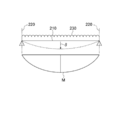
- FIG. 23 schematically shows a beam joining structure in which the beam is pinned to the structural member
- FIG. 24 shows the beam joining in which the beam is semi-rigidly connected to the structural member
- the structure is schematically shown
- FIG. 25 schematically shows a beam joint structure in which a beam is rigidly connected to a structural member.
- reference numeral 210 indicates a beam
- reference numeral 220 indicates a structural member
- reference numeral 230 indicates a slab.
- the symbol ⁇ indicates the deflection of the beam
- the symbol M indicates the magnitude of the bending moment of the beam.
- the small beam supported by the pin joint shown in FIG. 23 has a deflection of the central portion of the small beam as compared with the semi rigid joint having the bending moment resistance shown in FIGS. 24 and 25 or the thin beam supported by the rigid joint. And the bending moment increases. Therefore, the cross section of the beam is enlarged to suppress the deflection to increase the rigidity of the beam, or a beam with a large cross section or a high strength beam is required to withstand the bending moment. As a result, the weight of the beam and the unit price per weight increase, and as a result, it increases the construction cost of the building.
- a beam with a long span exceeding 10 m may be used to reduce the number of columns and widely use the space.
- the web of the beam is welded or bolted to the joint between the beam and the structural member.
- a rigid joint is used, in which the upper and lower flanges of the beam are joined to the structural members by welding or bolts.
- the contact plate is inserted between the lower flange of the beam and the structural member (post).
- the upper flange of the beam and the slab provided around the structural member are joined by a shear connector. Then, the compressive force of the beam is transmitted to the structural member through the contact plate, and the tensile force from the upper flange of the beam is transmitted to the structural member through the reinforcing bar disposed in the slab. Bending moment resistance is applied to the joint between the beam and the structural member.
- the deflection and bending moment of the central portion of the beam can be suppressed as compared with the pin connection in which only the web of the beam is joined to the structural member by a bolt.
- the beam and structural member are joined Since the reinforcement of the part is simple, the increase in the process and cost can be minimized.
- the width of the gap can be obtained. It is conceivable to prepare a plurality of contact plates of different widths in consideration of the variation of. However, in this case, there is a problem that the cost is increased due to the loss of material and the construction labor.
- the gap is generated in a state in which a horizontal gap is generated between the lower flange of the beam, which is formed of a horizontally extending H-shaped steel, and the structural member. Bonding the small beam to the structural member on the upper side, and inserting the first weir member having a first inclined surface obliquely upward facing the structural member in the horizontal direction into the gap, The fixing step of fixing to the flange, and moving the second wedge member downward while making the second inclined surface of the second wedge member slide down on the first inclined surface, the second wedge member is moved And a press-fit step of press-fitting between the structural member and the first wedge member.
- the beam joining method when the second wedging member moves downward while the second inclined surface of the second weir is in sliding contact with the first inclined surface of the first weir, The contact area between the second inclined surface and the first inclined surface expands downward. Thereby, the second weir member gradually moves to the structural member side, and the widths of the first weir member and the second weir member are expanded. Therefore, even if the width of the gap between the lower flange of the small beam and the structural member varies, the width of the first wedge member and the second wedge member can be matched to the width of this gap. The combined width allows the first wedge member and the second wedge member to be disposed between the lower flange of the girder and the structural member.
- the gap may be formed in a state in which a horizontal gap is created between the lower flange of the beam composed of H-shaped steel extending horizontally and the structural member.
- a joining step of joining the beam to the structural member on the upper side, and a first wedge member having a first inclined surface facing obliquely upward facing the lower flange inserted into the gap and fixed to the structural member And moving the second wedge member downward while bringing the second inclined surface in the second wedge member into sliding contact with the first inclined surface, and moving the second wedge member to the lower side.
- the beam joining method when the second wedging member moves downward while the second inclined surface of the second weir is in sliding contact with the first inclined surface of the first weir, The contact area between the second inclined surface and the first inclined surface expands downward. As a result, the second wedge member gradually moves toward the beam, and the widths of the first and second wedge members increase. Therefore, even if the width of the gap between the lower flange of the small beam and the structural member varies, the width of the first wedge member and the second wedge member can be matched to the width of this gap. The combined width allows the first wedge member and the second wedge member to be disposed between the lower flange of the girder and the structural member.
- the gap is formed in a state in which a horizontal gap is generated between the lower flange of the beam, which is formed of horizontally extending H-shaped steel, and the structural member.
- a joint that joins the beam to the structural member on the upper side, and a first inclined surface that is inserted into the gap and fixed to the lower flange and that faces the structural member in the horizontal direction and that is obliquely upward A second wedge member having a first wedge member having a second inclined surface in contact with the first inclined surface, the second wedge member being press-fit between the structural member and the first wedge member; Prepare.
- the beam joining structure relating to the third aspect of the present disclosure
- the second wedge member moves downward while the second inclined surface of the second wedge member slides on the first inclined surface of the first wedge member
- the contact area between the second inclined surface and the first inclined surface expands downward.
- the second weir member gradually moves to the structural member side, and the widths of the first weir member and the second weir member are expanded. Therefore, even if the width of the gap between the lower flange of the small beam and the structural member varies, the width of the first wedge member and the second wedge member can be matched to the width of this gap.
- the combined width allows the first wedge member and the second wedge member to be disposed between the lower flange of the girder and the structural member.
- the gap is formed in a state in which a horizontal gap is generated between the lower flange of the beam, which is formed of horizontally extending H-shaped steel, and the structural member.
- the beam joint structure relating to the fourth aspect of the present disclosure
- the second wedge member moves downward while the second inclined surface of the second wedge member slides on the first inclined surface of the first wedge member
- the contact area between the second inclined surface and the first inclined surface expands downward.
- the second wedge member gradually moves toward the beam, and the widths of the first and second wedge members increase. Therefore, even if the width of the gap between the lower flange of the small beam and the structural member varies, the width of the first wedge member and the second wedge member can be matched to the width of this gap.
- the combined width allows the first wedge member and the second wedge member to be disposed between the lower flange of the girder and the structural member.
- the support member according to the fifth aspect of the present disclosure is a support member according to a fifth aspect of the present disclosure, in which a horizontal gap is generated between the lower flange of the beam made of H-shaped steel extending horizontally and the structural member.
- a supporting member used in a beam joining structure having a joint portion joining the beam to the structural member on the upper side, which is inserted into the gap and fixed to the lower flange, and is horizontal to the structural member
- a first weir member having a first inclined surface facing obliquely upward, and a second inclined surface facing obliquely downward in contact with the first inclined surface, between the structural member and the first weir member And a second wedge member pressed into the
- the second wedge member when the second wedge member is moved downward while the second inclined surface of the second wedge member is in sliding contact with the first inclined surface of the first wedge member, the second The contact area between the inclined surface and the first inclined surface expands downward.
- the second weir member gradually moves to the structural member side, and the widths of the first weir member and the second weir member are expanded. Therefore, even if the width of the gap between the lower flange of the small beam and the structural member varies, the width of the first wedge member and the second wedge member can be matched to the width of this gap.
- the combined width allows the first wedge member and the second wedge member to be disposed between the lower flange of the girder and the structural member.
- a support member according to a sixth aspect of the present disclosure is a support member according to a sixth aspect of the present disclosure, in which a horizontal gap is generated between the lower flange of the beam made of H-shaped steel extending horizontally and the structural member.
- a supporting member used in a beam joining structure having a joint that joins the beam to the structural member on the upper side, which is inserted into the gap and fixed to the structural member, and is opposed to the lower flange
- a first wedge member having a first inclined surface that faces obliquely upward, and a second inclined surface that faces diagonally downward in contact with the first inclined surface, and press fitting between the lower flange and the first wedge member And a second weir member.
- the second wedge member when the second wedge member is moved downward while the second inclined surface of the second wedge member is in sliding contact with the first inclined surface of the first wedge member, the second The contact area between the inclined surface and the first inclined surface expands downward.
- the second wedge member gradually moves toward the beam, and the widths of the first and second wedge members increase. Therefore, even if the width of the gap between the lower flange of the small beam and the structural member varies, the width of the first wedge member and the second wedge member can be matched to the width of this gap.
- the combined width allows the first wedge member and the second wedge member to be disposed between the lower flange of the girder and the structural member.
- the compressive force from the beam lower flange while suppressing the increase in cost. can be transmitted to the structural member.
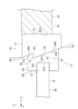
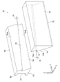
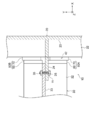
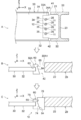
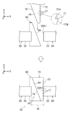
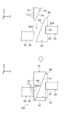
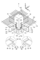
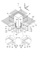
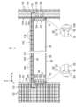
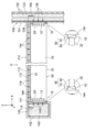
- FIG. 5 is a cross-sectional view taken along line F4-F4 of FIG. It is a figure explaining the beam joining method which concerns on 1st embodiment. It is a figure explaining the insertion direction of the 2nd weir member in the press-fit process of FIG. It is a figure which shows a mode that the 2nd wedge member is press-fit in the press-fit process of FIG. It is a figure which shows the support member which concerns on 2nd embodiment, and a press injection process.
- FIG. 1 It is a disassembled perspective view of the supporting member of FIG. It is a figure which shows the support member which concerns on 3rd embodiment, a press injection process, and a welding process. It is a figure which shows the support member which concerns on 4th embodiment, a fixing process, and a pressing-in process. It is a figure which shows the support member which concerns on 5th embodiment, and a press injection process. It is a figure which shows the support member which concerns on 6th embodiment, and a press injection process. It is a figure which shows the support member and press-in process which concern on 7th embodiment. It is front sectional drawing which shows the beam joint structure which concerns on 8th embodiment. It is front sectional drawing which shows the beam joint structure which concerns on 9th embodiment.
- FIG. 18 is a cross-sectional view taken along line F18-F18 of FIG. 17; It is a perspective view which shows the beam joint structure which concerns on 11th embodiment. It is front sectional drawing which shows the beam joint structure which concerns on 12th embodiment. It is front sectional drawing which shows the beam joint structure which concerns on 13th embodiment. It is front sectional drawing which shows the beam joint structure which concerns on 14th embodiment. It is a figure which shows typically the beam joint structure with which the beam was pin-joined to the structural member. It is a figure which shows typically the beam joint structure with which the beam was semi-rigidly joined to the structural member. It is a figure which shows typically the beam joint structure with which the beam was rigidly joined to the structural member.
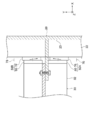
- the building structure S shown in FIG. 1 is applied to, for example, a building such as a building, and includes a girder 20 and a girder 30.
- the arrow X direction, the arrow Y direction, and the arrow Z direction shown in each drawing are orthogonal to each other.
- the arrow X direction and the arrow Y direction are directions parallel to the horizontal direction.
- the arrow Z direction corresponds to the vertical direction, and the side indicated by the arrow Z corresponds to the upper side in the vertical direction.
- the girder 20 is an example of the “structural member”.
- the girder 20 extends in the arrow Y direction.
- the girder 20 is formed of an H-shaped steel having an upper flange 21, a lower flange 22 and a web 23.
- the upper flange 21 and the lower flange 22 extend in the arrow X direction
- the web 23 extends in the arrow Z direction.
- the web 23 connects the central portion of the upper flange 21 in the arrow X direction and the central portion of the lower flange 22 in the arrow X direction.
- the beam 30 extends in the arrow X direction.
- the beam 30 is formed of an H-shaped steel having an upper flange 31, a lower flange 32 and a web 33.
- the upper flange 31 and the lower flange 32 extend in the arrow Y direction
- the webs 33 extend in the arrow Z direction.
- the web 33 connects a central portion in the arrow Y direction in the upper flange 31 and a central portion in the arrow Y direction in the lower flange 32.
- the height dimension H2 of the small beam 30 is substantially the same as the height dimension H1 of the large beam 20, and the small beam 30 is disposed in the vicinity of the large beam 20 in the arrow X direction.
- the girder 20 includes the shear plate 24.
- the shear plate 24 is formed in a rectangular shape whose thickness direction is in the direction of the arrow Y.
- the shear plate 24 extends from the web 23 of the girder 20 toward the girder 30.
- the portion on the side of the small beam 30 in the shear plate 24 is the tip 24 A of the shear plate 24, and the portion on the web 23 side in the shear plate 24 is the proximal end 24 B of the shear plate 24.
- the base end 24 B of the shear plate 24 is joined to the upper flange 21, the lower flange 22 and the web 23 of the large beam 20 by welding.
- the tip end portion 24 ⁇ / b> A of the shear plate 24 protrudes toward the beam 30 side more than the upper flange 21 and the lower flange 22 of the large beam 20.
- the front end portion 24A of the shear plate 24 is disposed between the upper flange 31 and the lower flange 32 of the beam 30, and is overlapped in the arrow Y direction on the portion 33A of the web 33 of the beam 30 on the large beam 20 side. ing.
- a plurality of through holes 25 penetrating in the direction of the arrow Y are formed in the end portion 24A of the shear plate 24.
- the plurality of through holes 25 are arranged in the arrow Z direction.
- a plurality of through holes 35 penetrating in the arrow Y direction are formed in a portion 33A of the web 33 of the beam 30 at the side of the large beam 20.
- the plurality of through holes 35 are formed at positions aligned with the plurality of through holes 25 formed in the shear plate 24.
- a fastening member 11 having a bolt and a nut is used for joining the shear plate 24 and the web 33 of the beam 30. That is, the bolts of the fastening member 11 are inserted into the through holes 25 and 35, and the nut of the fastening member 11 is screwed into the tip of the bolt, whereby the shear plate 24 and the web 33 are joined.
- the junction between the shear plate 24 and the web 33 is a junction 12.
- the upper flange 21 and the upper flange 31 are opposed in the arrow X direction with the gap 41 in the arrow X direction.
- the lower flange 22 and the lower flange 32 face each other in the arrow X direction with the gap 42 in the arrow X direction.
- the length of the shear plate 24 in the arrow X direction and the positions of the plurality of through holes 25 and 35 in the arrow X direction are set so that the gaps 41 and 42 in the arrow X direction are generated.
- the joint 12 between the shear plate 24 and the web 33 is located below the upper gap 41 and above the lower gap 42.
- a slab (for example, a concrete floor slab) is provided on the upper flange 21 of the girder 20 and the upper flange 31 of the girder 30.
- the slab is joined to the girder 20 and the girder 30 by shear connectors provided on the upper flange 21 of the girder 20 and the upper flange 31 of the girder 30.
- the example in which the slab is provided on the upper flange 21 of the large beam 20 and the upper flange 31 of the small beam 30 is described in the eighth and ninth embodiments (see FIGS. 15 and 16) described later.
- a support member 50 (reinforcement member) is disposed in a gap 42 between the lower flange 22 and the lower flange 32.
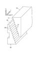
- the support member 50 includes a first wedge member 60 and a second wedge member 70.
- the first wedge member 60 and the second wedge member 70 are made of, for example, steel or carbon fiber reinforced plastic.
- the first wedge member 60 is inserted into the gap 42 and fixed to the lower flange 32.
- the second wedge member 70 is press-fitted between the lower flange 22 and the first wedge member 60.
- the first wedge member 60 is formed with a groove 61 extending in the arrow Y direction.
- the groove 61 is opened in the surface 62 on the lower flange 32 side of the first wedge member 60 and is opened in the side surface 63 on both sides in the arrow Y direction of the first wedge member 60.
- the first wedge member 60 is fixed to the lower flange 32 by inserting the end 32 ⁇ / b> A of the lower flange 32 into the groove 61.
- a first inclined surface 64 obliquely upward is formed on the side of the second wedging member 70 in the first weir member 60.
- the first inclined surface 64 is opposed to the end face 22A1 of the lower flange 22 in the arrow X direction via the second wedge member 70.
- a downward first step surface 65 is formed on the first inclined surface 64.
- the first step surface 65 is an example of the “first guide surface”.
- the length (width) of the first step surface 65 in the arrow X direction is, for example, 5 to 20 mm.
- the upper side of the first inclined surface 64 above the first stepped surface 65 is formed as the upper inclined surface 64A, and the lower side of the first inclined surface 64 than the first stepped surface 65 is formed as the lower inclined surface 64B. It is done.
- the inclination angle theta Z for the Z-direction of the upper inclined surface 64A and the lower inclined surface 64B are the same.
- the inclination angle theta Z is, for example, 5 ⁇ 30 °, desirably a 10 ⁇ 15 °.
- the surface 72 on the lower flange 22 side of the second wedge member 70 is a flat surface without a groove or the like, and extends in the arrow Z direction.
- a second inclined surface 74 obliquely downward is formed on the side of the first weir member 60 in the second weir member 70.
- An upward second step surface 75 is formed on the second inclined surface 74.
- the second step surface 75 is an example of the “second guide surface”. The second step surface 75 is locked to the first step surface 65 from the lower side, whereby the second wedge member 70 is prevented from coming off.
- the upper side of the second inclined surface 74 above the second stepped surface 75 is formed as the upper inclined surface 74A, and the lower side of the second inclined surface 74 below the second stepped surface 75 is formed as the lower inclined surface 74B. It is done.
- the inclination angles with respect to the arrow Z direction of the upper inclined surface 74A and the lower inclined surface 74B are the same.
- the inclination angles of the upper inclined surface 74A and the lower inclined surface 74B with respect to the arrow Z direction are the same as the inclination angles ⁇ Z of the upper inclined surface 64A and the lower inclined surface 64B of the first wedge member 60 with respect to the arrow Z direction. It is.
- the second wedge member 70 is press-fitted between the lower flange 22 of the girder 20 and the first wedge member 60 as described above.
- the first wedge member 60 is pressed toward the lower flange 32 by the second wedge member 70, and the bottom surface 61A of the groove 61 is in contact with the end surface 32A1 of the lower flange 32 in a pressed state.
- the upper inclined surface 74A and the lower inclined surface 74B of the second inclined surface 74 contact the upper inclined surface 64A and the lower inclined surface 64B of the first inclined surface 64 in a pressed state, respectively, and the second wedge member 70
- the surface 72 on the lower flange 22 side is in contact with the end surface 22A1 of the lower flange 22 in a pressed state.
- the first step surface 65 and the second step surface 75 extend in the arrow Y direction.
- the first step surface 65 and the second step surface 75 are inclined with respect to the direction of the arrow Y so as to move downward toward the side indicated by the arrow Y.
- the inclination angles ⁇ Y of the first step surface 65 and the second step surface 75 with respect to the arrow Y direction are the same.
- the arrow Y direction corresponds to the width direction of the small beam 30 (see FIGS. 1 and 2)
- the side opposite to the side indicated by the arrow Y corresponds to one width direction side of the small beam 30,
- the side indicated by Y corresponds to the other side in the width direction of the beam 30.
- a pair of support members 50A and 50B are disposed in the gap 42 between the lower flange 22 and the lower flange 32.
- the pair of support members 50A and 50B are respectively disposed on both sides in the arrow Y direction across the shear plate 24 and the web 33.
- the pair of support members 50A, 50B are formed symmetrically in the arrow Y direction.
- the above description (see FIGS. 1 to 3) is the description of one of the support members 50A.
- the beam joining method according to the first embodiment includes a joining step A, a fixing step B, and a press-in step C.
- the small beam 30 is disposed in the vicinity of the large beam 20 in the arrow X direction.
- the tip end portion 24A of the shear plate 24 is disposed between the upper flange 31 and the lower flange 32 of the small beam 30, and is overlapped in the arrow Y direction with the portion 33A of the web 33 of the small beam 30 side. Be done.
- the plurality of through holes 25 formed in the shear plate 24 are aligned with the plurality of through holes 35 formed in the web 33 of the beam 30.
- the shear plate 24 and the web 33 are joined by the fastening member 11 which has a volt
- a gap 41 in the arrow X direction is generated between the upper flange 21 and the upper flange 31, and the lower flange 22 and the lower flange A gap 42 in the direction of the arrow X is generated between them and 32.
- the small beam 30 is more than the gap 42 in the state in which the gap 42 in the arrow X direction is generated between the lower flange 32 of the small beam 30 and the lower flange 22 of the large beam 20. It is joined to the girder 20 at the upper joint 12.
- the first wedge member 60 is inserted into the gap 42, and the end 32A of the lower flange 32 formed on the small beam 30 is inserted into the groove 61 of the first wedge member 60.
- the first wedge member 60 is fixed to the lower flange 32.
- the obliquely upward first inclined surface 64 opposes the end face 22A1 of the lower flange 22 formed on the large beam 20 with a gap in the arrow X direction.
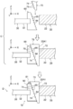
- the second wedge member 70 is press-fitted between the lower flange 22 and the first wedge member 60.
- the second wedge member 70 of one of the support members 50A is inserted into the gap between the lower flange 22 and the first wedge member 60 toward the side indicated by the arrow Y. Ru.
- the second wedge member 70 of the other support member 50B is inserted into the gap between the lower flange 22 and the first wedge member 60 toward the opposite side to the side indicated by the arrow Y.
- the pair of support members 50A and 50B are formed symmetrically in the arrow Y direction as described above.
- the pair of support members 50A will be described, and the description of the other support member 50B will be omitted.
- the second wedge member 70 is inserted into the gap between the lower flange 22 and the first wedge member 60 toward the side indicated by the arrow Y.
- the second step surface 75 is positioned below the first step surface 65 and is in sliding contact with the first step surface 65.
- the upper view of FIG. 7 shows an initial stage in which the second wedge member 70 is inserted.
- one end of the first step surface 65 (the end opposite to the side indicated by the arrow Y) and one end of the second step surface 75 (the end indicated by the arrow Y) And the lower insertion amount of the second wedge member 70 is small.
- FIG. 7 shows a state in which the press-fitting of the second wedge member 70 is completed.
- the second wedge member 70 when the second wedge member 70 is inserted toward the side indicated by the arrow Y, the second step surface 75 is in sliding contact with the first step surface 65. , And the second wedge member 70 moves downward.
- the contact region between the second inclined surface 74 and the first inclined surface 64 spreads downward, whereby the second wedge member 70 is gradually moved to the lower flange 22 side.
- the surface 72 on the lower flange 22 side of the second wedge member 70 contacts the end surface 22A1 of the lower flange 22.
- the small beam 30 is fixed to the large beam 20 as described above.
- the first step surface 65 and the second step surface 75 formed on the first and second wedge members 60 and 70 are inclined with respect to the arrow Y direction. ing. Then, when the second wedge member 70 is inserted into the gap between the lower flange 22 and the first wedge member 60 along the arrow Y direction, the second step surface 75 is in sliding contact with the first step surface 65. As a result, the second wedge member 70 moves downward. Further, the first inclined surface 64 and the second inclined surface 74 formed on the first wedge member 60 and the second wedge member 70 are tilted with respect to the arrow Z direction.
- the width W of the gap 42 between the lower flange 22 and the lower flange 32 can be matched to the width of the first wedge member 60 and the second wedge member 70. Therefore, the first wedge member 60 and the second wedge member 70 can be disposed between the lower flange 22 and the lower flange 32 with a width adjusted to the width W of the gap 42. Thereby, even if the width W of the gap 42 varies, the compression force from the lower flange 32 of the small beam 30 can be transmitted to the lower flange 22 of the large beam 20 via the first wedge member 60 and the second wedge member 70. . In addition, since it is not necessary to prepare a plurality of first wedge members 60 and second wedge members 70 having different widths in consideration of the variation in the width W of the gap 42, an increase in cost can be suppressed.
- the second wedge member 70 is inserted into the gap between the lower flange 22 and the first wedge member 60 along the arrow Y direction, and the second step surface 75 is the first step By sliding contact with the surface 65, the second weir member 70 moves downward. Therefore, for example, even if there is no space for inserting the second wedge member 70 along the arrow Z direction on the upper and lower sides of the gap between the lower flange 22 and the first wedge member 60, the second wedge The member 70 can be inserted into the gap between the lower flange 22 and the first wedge member 60.
- the second step surface 75 is locked to the first step surface 65 from the lower side. Therefore, it can suppress that the 2nd weir member 70 slips out upwards.
- the configurations of the first wedge member 60 and the second wedge member 70 are modified as follows with respect to the above-described first embodiment (see FIG. 2). That is, on the first inclined surface 64, a plurality of first step surfaces 65 are formed. The plurality of first step surfaces 65 are formed at intervals from the upper side to the lower side of the first inclined surface 64. Similarly, on the second inclined surface 74, a plurality of second step surfaces 75 are formed. The plurality of second step surfaces 75 are formed at intervals from the upper side to the lower side of the second inclined surface 74.
- the first step surface 65 and the second step surface 75 extend in the arrow Y direction, and the first wedge member 60 and the second wedge member 70 have a constant cross section in the arrow Y direction. It is formed. 8 and 9, the sizes of the first step surface 65 and the second step surface 75 are exaggerated.
- the length (width) of the first step surface 65 and the second step surface 75 in the arrow X direction is, for example, 1 to 2 mm.
- the press-in process C is modified as follows with respect to the above-described first embodiment (see FIGS. 5 to 7). That is, in the press-in process C, the second wedge member 70 is inserted into the gap between the lower flange 22 and the first wedge member 60 from the upper side. At this time, the second wedge member 70 is moved downward while the second inclined surface 74 is in sliding contact with the first inclined surface 64. When the second wedge member 70 moves downward, the contact region between the second inclined surface 74 and the first inclined surface 64 expands downward, and the second wedge member 70 gradually moves to the lower flange 22 side. The surface 72 on the lower flange 22 side of the second wedge member 70 contacts the end surface 22A1 of the lower flange 22.
- each second step surface 75 passes over one or more first step surfaces 65 according to the amount of pushing of the second weir member 70, and the second The wedge member 70 is press-fit between the lower flange 22 and the first wedge member 60. Moreover, in this state, the second wedge member 70 is prevented from coming off by the plurality of second step surfaces 75 being locked from the lower side to the plurality of first step surfaces 65.
- the small beam 30 is fixed to the large beam 20 as described above.
- the second inclined member 74 is gradually enlarged by the second inclined surface 74 being in sliding contact with the first inclined surface 64. Then, the width of the first wedge member 60 and the second wedge member 70 (that is, the width of the support member 50) is expanded.
- the width W of the gap 42 between the lower flange 22 and the lower flange 32 can be matched to the width of the first wedge member 60 and the second wedge member 70. Therefore, the first wedge member 60 and the second wedge member 70 can be disposed between the lower flange 22 and the lower flange 32 with a width adjusted to the width W of the gap 42. Thereby, even if the width W of the gap 42 varies, the compression force from the lower flange 32 of the small beam 30 can be transmitted to the lower flange 22 of the large beam 20 via the first wedge member 60 and the second wedge member 70. . In addition, since it is not necessary to prepare a plurality of first wedge members 60 and second wedge members 70 having different widths in consideration of the variation in the width W of the gap 42, an increase in cost can be suppressed.
- the plurality of second step surfaces 75 are engaged with the plurality of first step surfaces 65 from the lower side. Therefore, it can suppress that the 2nd weir member 70 slips out upwards.
- a welding portion 81 for fixing the upper portion of the first wedge member 60 and the upper portion of the second wedge member 70 is added to the above-described second embodiment (see FIG. 8) ing.
- the welding step D is added after the press-in step C with the addition of the welding portion 81.
- the upper portion of the first wedge member 60 and the upper portion of the second wedge member 70 are fixed by the welding portion 81.
- the second wedge member is fixed by the welding portion 81 fixing the upper portion of the first wedge member 60 and the upper portion of the second wedge member 70. It is possible to more effectively suppress the upward displacement of the 70.
- the welding portion 81 may be provided at a portion other than the upper portion of the first wedge member 60 and the second wedge member 70.
- welding portion 81 in the third embodiment may be applied to the first wedge member 60 and the second wedge member 70 in the first embodiment.
- the configurations of the first wedge member 60 and the second wedge member 70 are changed as follows with respect to the above-described first embodiment (see FIG. 2). That is, the surface 62 on the lower flange 32 side of the first wedge member 60 is a flat surface without a groove or the like, and extends in the arrow Z direction. The surface 62 on the lower flange 32 side of the first wedge member 60 is fixed to the end 32 A of the lower flange 32 at the upper and lower sides of the lower flange 32 by a welding portion 82.
- the first inclined surface 64 of the first wedge member 60 and the second inclined surface 74 of the second wedge member 70 are each formed as a flat surface having no step or the like.
- the fixing step B and the press-in step C are modified as follows with respect to the above-described first embodiment (see FIGS. 5 to 7). That is, in the fixing step B, the first wedge member 60 is inserted into the gap 42, and the surface 62 on the lower flange 32 side of the first wedge member 60 abuts on the end surface 32A1 of the lower flange 32. Further, in this state, the surface 62 on the lower flange 32 side of the first wedge member 60 is fixed to the end 32 A of the lower flange 32 at the upper and lower sides of the lower flange 32 by the welding portion 82.
- the second wedge member 70 is inserted into the gap between the lower flange 22 and the first wedge member 60 from the upper side. At this time, the second wedge member 70 is moved downward while the second inclined surface 74 is in sliding contact with the first inclined surface 64. When the second wedge member 70 moves downward, the contact region between the second inclined surface 74 and the first inclined surface 64 expands downward, and the second wedge member 70 gradually moves to the lower flange 22 side. The surface 72 on the lower flange 22 side of the second wedge member 70 contacts the end surface 22A1 of the lower flange 22. From this state, when the second wedge member 70 is pushed downward, the second wedge member 70 is press-fit between the lower flange 22 and the first wedge member 60.
- the second inclined member 74 is gradually enlarged by the second inclined surface 74 being in sliding contact with the first inclined surface 64. Then, the width of the first wedge member 60 and the second wedge member 70 (that is, the width of the support member 50) is expanded.
- the width W of the gap 42 between the lower flange 22 and the lower flange 32 can be matched to the width of the first wedge member 60 and the second wedge member 70. Therefore, the first wedge member 60 and the second wedge member 70 can be disposed between the lower flange 22 and the lower flange 32 with a width adjusted to the width W of the gap 42. Thereby, even if the width W of the gap 42 varies, the compression force from the lower flange 32 of the small beam 30 can be transmitted to the lower flange 22 of the large beam 20 via the first wedge member 60 and the second wedge member 70. . In addition, since it is not necessary to prepare a plurality of first wedge members 60 and second wedge members 70 having different widths in consideration of the variation in the width W of the gap 42, an increase in cost can be suppressed.
- first inclined surface 64 and the second inclined surface 74 may be formed of a rough surface in order to prevent the second wedge member 70 from coming off, and the first wedge member 60 and the first wedge member 60 may also be used.
- the second wedge member 70 may be fixed by welding, adhesion or the like.
- welding portion 82 in the fourth embodiment may be applied to the first wedge member 60 in the first to third embodiments.
- the configuration of the support member 50 is changed as follows with respect to the above-described first embodiment (see FIG. 2). That is, the first weir member 60 has a first groove 66 extending in the arrow Y direction, and the second weir member 70 has a second groove 76 extending in the arrow Y direction.
- the first groove 66 is open to the first inclined surface 64 and is open to the side surface 63 of the first wedge member 60.
- the second groove 76 opens to the second inclined surface 74 and opens to the side surface 73 of the second wedge member 70.
- the upper wall surface 66A of the first groove 66 is above the lower wall surface 76A of the second groove 76.
- the positions of the first groove 66 and the second groove 76 are set to be positioned.
- the support member 50 includes a third wedge member 90.
- the third weir member 90 is inserted between the upper wall surface 66A of the first groove 66 and the lower wall surface 76A of the second groove 76.
- the third weir member 90 has a first sliding contact surface 91 in sliding contact with the upper wall surface 66A and a second sliding contact surface 92 in sliding contact with the lower wall surface 76A.
- the third wedge member 90 is formed in a trapezoidal block shape in which the first sliding surface 91 is an inclined surface and the second sliding surface 92 is a vertical surface.
- the first sliding contact surface 91 is inclined with respect to the second sliding contact surface 92, and the width between the first sliding contact surface 91 and the second sliding contact surface 92 is the tip side of the third weir member 90. Expand toward the rear end side from.
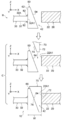
- the press-in process C is modified as follows with respect to the above-described first embodiment (see FIGS. 5 to 7). That is, the press-in process C has a first stage C1 to a third stage C3.
- the second wedge member 70 is inserted between the lower flange 22 and the first wedge member 60 from the upper side.
- the second wedge member 70 may be inserted between the lower flange 22 and the first wedge member 60 along the arrow Y direction.
- the third weir member 90 is inserted between the upper wall surface 66A of the first groove 66 and the lower wall surface 76A of the second groove 76.
- the third wedge member 90 is pushed.
- the first sliding contact surface 91 is in sliding contact with the wall surface 66A
- the second sliding contact surface 92 is in sliding contact with the wall surface 76A
- the wall surface 76A is pushed down with respect to the wall surface 66A.
- the second wedge member 70 moves downward, and the second wedge member 70 is press-fitted between the lower flange 22 and the first wedge member 60. In this state, the second weir member 70 is prevented from coming off by the third weir member 90 being interposed between the wall surface 66A and the wall surface 76A.
- the wall surface relative to the wall surface 66A 76A is pushed down, and the second wedge member 70 moves downward.
- the second wedge member 70 gradually moves to the large beam 20 side by the second inclined surface 74 slidingly contacting with the first inclined surface 64, The width of the first wedge member 60 and the second wedge member 70 (that is, the width of the support member 50) is expanded.
- the width W of the gap 42 between the lower flange 22 and the lower flange 32 can be matched to the width of the first wedge member 60 and the second wedge member 70. Therefore, the first wedge member 60 and the second wedge member 70 can be disposed between the lower flange 22 and the lower flange 32 with a width adjusted to the width W of the gap 42. Thereby, even if the width W of the gap 42 varies, the compression force from the lower flange 32 of the small beam 30 can be transmitted to the lower flange 22 of the large beam 20 via the first wedge member 60 and the second wedge member 70. . In addition, since it is not necessary to prepare a plurality of first wedge members 60 and second wedge members 70 having different widths in consideration of the variation in the width W of the gap 42, an increase in cost can be suppressed.
- the third weir member 90 is inserted between the upper wall surface 66A of the first groove 66 and the lower wall surface 76A of the second groove 76 along the arrow Y direction. Then, the second wedge member 70 moves downward, and the second wedge member 70 is press-fit into the gap between the lower flange 22 and the first wedge member 60.
- a space for press-fitting the second wedge member 70 into the gap between the lower flange 22 and the first wedge member 60 is the upper side of the gap between the lower flange 22 and the first wedge member 60 and Even when there is no lower side, the second wedge member 70 can be press-fit into the gap between the lower flange 22 and the first wedge member 60.
- the upper wall surface 66A and the lower wall surface 76A The third weir member 90 intervenes between them. Therefore, it can suppress that the 2nd weir member 70 slips out upwards.
- the configurations of the first wedge member 60 and the second wedge member 70 are modified as follows with respect to the above-described first embodiment (see FIG. 2). That is, the first inclined surface 64 and the second inclined surface 74 are formed as flat surfaces having no steps or grooves. Further, on the surface 72 on the lower flange 22 side of the second wedge member 70, a plurality of convex portions 77 that protrude to the lower flange 22 side are formed. The plurality of protrusions 77 are formed at intervals from the upper side to the lower side of the surface 72 on the lower flange 22 side.
- the convex portion 77 is formed in the shape of a step having the step surface 77A and the inclined surface 77B.
- the stepped surface 77A is formed upward.
- the inclined surface 77B is located on the lower side of the step surface 77A, and is inclined with respect to the arrow Z direction toward the second inclined surface 74 as it goes downward.
- the size of the convex portion 77 is exaggerated.
- the length in the direction of the arrow X (the width of the step surface 77A) of the convex portion 77 is, for example, 1 to 2 mm.
- the press-in process C is modified as follows with respect to the above-described first embodiment (see FIGS. 5 to 7). That is, in the press-in process C, the second wedge member 70 is inserted into the gap between the lower flange 22 and the first wedge member 60 from the upper side. At this time, the second wedge member 70 is moved downward while the second inclined surface 74 is in sliding contact with the first inclined surface 64.
- the second inclined member 74 is gradually enlarged by the second inclined surface 74 being in sliding contact with the first inclined surface 64. Then, the width of the first wedge member 60 and the second wedge member 70 (that is, the width of the support member 50) is expanded.
- the width W of the gap 42 between the lower flange 22 and the lower flange 32 can be matched to the width of the first wedge member 60 and the second wedge member 70. Therefore, the first wedge member 60 and the second wedge member 70 can be disposed between the lower flange 22 and the lower flange 32 with a width adjusted to the width W of the gap 42. Thereby, even if the width W of the gap 42 varies, the compression force from the lower flange 32 of the small beam 30 can be transmitted to the lower flange 22 of the large beam 20 via the first wedge member 60 and the second wedge member 70. . In addition, since it is not necessary to prepare a plurality of first wedge members 60 and second wedge members 70 having different widths in consideration of the variation in the width W of the gap 42, an increase in cost can be suppressed.
- the second wedge member 70 is press-fitted between the lower flange 22 and the first wedge member 60 in a state where the plurality of convex portions 77 bite into the end face 22A1 of the lower flange 22. Be done. Therefore, it can suppress that the 2nd weir member 70 slips out upwards.
- the plurality of convex portions 77 in the sixth embodiment may be applied to the second weir member 70 in the first to fifth embodiments.
- the configurations that can be combined may be implemented in combination as appropriate.
- the first weir member 60 and the second weir member 70 are compared to the beam joint structure 10 according to the sixth embodiment described above (see FIG. 13).
- the arrangement of has been changed as follows. That is, the first wedge member 60 is disposed on the large beam 20 side, and the second wedge member 70 is disposed on the small beam 30 side.
- the end 22A of the lower flange 22 is inserted into the groove 61 of the first wedge member 60, whereby the first wedge member 60 is fixed to the lower flange 22.
- the second wedge member 70 is press-fitted between the lower flange 32 and the first wedge member 60, and the plurality of convex portions 77 bite into the end surface 32A1 of the lower flange 32.
- the fixing step and the press-fitting step are performed as follows. That is, in the fixing step, the first wedge member 60 is inserted into the gap 42, and the end 22A of the lower flange 22 formed on the large beam 20 is inserted into the groove 61 of the first wedge member 60. The first wedge member 60 is fixed to the lower flange 22.
- the second wedge member 70 is inserted into the gap between the lower flange 32 and the first wedge member 60 from the upper side. At this time, the second wedge member 70 is moved downward while the second inclined surface 74 is in sliding contact with the first inclined surface 64.
- the second inclined member 74 when the second wedging member 70 moves downward, the second inclined member 74 is gradually brought into contact with the second inclined surface 74 in sliding contact with the first inclined surface 64. It moves to the small beam 30 side, and the width of the first wedge member 60 and the second wedge member 70 (that is, the width of the support member 50) is expanded.
- the width W of the gap 42 between the lower flange 22 and the lower flange 32 can be matched to the width of the first wedge member 60 and the second wedge member 70. Therefore, the first wedge member 60 and the second wedge member 70 can be disposed between the lower flange 22 and the lower flange 32 with a width adjusted to the width W of the gap 42. Thereby, even if the width W of the gap 42 varies, the compression force from the lower flange 32 of the small beam 30 can be transmitted to the lower flange 22 of the large beam 20 via the first wedge member 60 and the second wedge member 70. . In addition, since it is not necessary to prepare a plurality of first wedge members 60 and second wedge members 70 having different widths in consideration of the variation in the width W of the gap 42, an increase in cost can be suppressed.
- the second wedge member 70 is press-fit between the lower flange 32 and the first wedge member 60 in a state where the plurality of convex portions 77 bite into the end face 32A1 of the lower flange 32. Be done. Therefore, it can suppress that the 2nd weir member 70 slips out upwards.
- the building structure S includes a girder 20, a pair of beamlets 30, a plurality of support members 50, and a slab 110.
- the pair of beamlets 30 are respectively disposed on both sides of the large beam 20 in the arrow X direction.
- a beam joint structure 10 is applied to the connection between each beam 30 and the large beam 20, respectively. That is, the girder 20 includes a pair of shear plates 24. The pair of shear plates 24 extend from the large beam 20 toward the respective small beams 30 respectively. A beam 30 is joined to each shear plate 24. The configuration of the joint 12 between each beam 30 and the shear plate 24 is symmetrical in the arrow X direction.
- the height dimension H 2 of the small beam 30 is smaller than the height dimension H 1 of the large beam 20, and the lower flange 32 of each small beam 30 is located above the lower flange 22 of the large beam 20.
- the web 23 of the girder 20 is formed with a pair of ribs 26.
- the pair of ribs 26 extend toward the respective beams 30.
- the configuration other than the above of the large beam 20 and the pair of small beams 30 is the same as that of the above-described first embodiment (see FIG. 1).
- a gap 42 is formed between the lower flange 32 of each beam 30 and each rib 26.
- Support members 50 are disposed in the respective gaps 42.
- the configuration of the above-described fourth embodiment (see FIG. 11) is applied to the first wedge member 60 and the second wedge member 70 of the support member 50 as an example.
- the slab 110 is provided on the large beam 20 and the pair of small beams 30.
- the slab 110 is composed of a plurality of reinforcing bars 112 and concrete 113.
- the large beam 20 and the pair of small beams 30 and the concrete 113 are joined by a plurality of shear connectors 114 provided on the upper surfaces of the large beam 20 and the pair of small beams 30.
- a plurality of deck plates 115 are provided on the upper surfaces of the large beam 20 and the pair of small beams 30.
- the support member 50 is inserted in the gap 42 between the lower flange 32 of each beam 30 and the rib 26 of the large beam 20, the lower side of each beam 30 is provided.
- the compression force from the flange 32 can be transmitted to the girder 20.
- the upper flange 21 of the large beam 20 and the upper flange 31 of the small beam 30 and the concrete 113 of the slab 110 are joined by the shear connector 114, the tensile force from the upper flange 31 of the small beam 30 is distributed to the slab 110 It can be transmitted to the girder 20 through the rebar 112.
- the configuration of the fourth embodiment is applied to the first wedge member 60 and the second wedge member 70 as an example, but the first, second, third, and third components described above are used.
- the configuration of any of the fifth, sixth and seventh embodiments may be applied.
- the configuration of the beam joint structure 10 is changed as follows with respect to the above-described eighth embodiment (see FIG. 15). That is, the web 33 and the lower flange 32 of each beam 30 are extended to a position close to the web 23 of the girder 20 in the arrow X direction, and the lower flange 32 of each beam 30 and the web of the girder 20 There are gaps 42 between them and 23, respectively. Support members 50 are disposed in the respective gaps 42.
- the configuration of the above-described fourth embodiment is applied to the first wedge member 60 and the second wedge member 70 of the support member 50 as an example.
- the support member 50 is inserted in the gap 42 between the lower flange 32 of each beam 30 and the web 23 of the large beam 20, the lower side of each beam 30 is obtained.
- the compression force from the flange 32 can be transmitted to the girder 20.
- the upper flange 21 of the large beam 20 and the upper flange 31 of the small beam 30 and the concrete of the slab 110 are joined by the shear connector 114, the tensile force from the upper flange 31 of the small beam 30 is distributed to the slab 110 It can be transmitted to the girder 20 through the rebar 112.
- the configuration of the fourth embodiment is applied to the first wedge member 60 and the second wedge member 70 as an example, but the first, second, third, and the above-described ones are applied.
- the configuration of any of the fifth, sixth and seventh embodiments may be applied.
- the building structure S includes a column 120, a plurality of beamlets 30, a plurality of support members 50, and a slab 110.
- the pillar 120 is an example of a “structural member” and extends in the arrow Z direction.
- the cross-sectional shape of the column 120 cut in the horizontal direction is a quadrangle, and the plurality of small beams 30 extend in the normal direction of each side surface 121 from the plurality of side surfaces 121 formed in the column 120.
- the column 120 is made of reinforced concrete composed of a plurality of reinforcing bars 122 and concrete 123.
- a beam joint structure 10 is applied to the connection between each beam 30 and the column 120, respectively. That is, on each side surface 121 of the pillar 120, a support plate 124 is provided. The support plate 124 is joined with a plurality of studs 125 extending toward the inside of the column 120, and the support plate 124 and the concrete 123 are joined by a plurality of studs 125.
- the support plate 124 is exposed to the side surface 121 of the pillar 120 and constitutes a part of the side surface 121.
- a shear plate 24 is joined to each support plate 124, respectively. Each shear plate 24 extends in the normal direction of the side surface 121 from the side surface 121 (support plate 124).
- a beam 30 is joined to each shear plate 24.
- the configuration of the joint 12 between each beam 30 and the shear plate 24 is the same.
- the configuration of the joint 12 between each beam 30 and the shear plate 24 is the same as that of the first embodiment described above (see FIG. 1).
- a gap 42 is created between the lower flange 32 of the beam 30 and the support plate 124.
- the support member 50 is disposed in the gap 42.
- the configuration of the above-described fourth embodiment (see FIG. 11) is applied to the first wedge member 60 and the second wedge member 70 of the support member 50 as an example.
- the slab 110 is provided on the plurality of beamlets 30.
- the slab 110 is composed of a plurality of reinforcing bars 112 and concrete 113. In FIG. 17, only some of the plurality of reinforcing bars 112 used for the slab 110 are illustrated for the sake of convenience.
- the plurality of beamlets 30 and the concrete 113 are joined by a plurality of shear connectors 114 provided on the upper surface of each beamlet 30. Further, the slab 110 and the pillars 120 are connected by the connection member 116.
- the support member 50 is inserted in the gap 42 between the lower flange 32 of each beam 30 and the side surface 121 of the column 120, the lower side of each beam 30 is obtained.
- the compressive force from the flange 32 can be transmitted to the column 120.
- the upper flange 31 of the beam 30 and the slab 110 are joined by the shear connector 114 and the slab 110 and the column 120 are connected by the connecting member 116, tension from the upper flange 31 of the beam 30 is obtained.
- the force can be transmitted to the column 120 via the rebar 112 and the connection member 116 arranged on the slab 110.
- the configuration of the fourth embodiment is applied to the first wedge member 60 and the second wedge member 70 as an example, but the first, second, third, and fourth embodiments described above are used.
- the configuration of any of the fifth, sixth and seventh embodiments may be applied.
- the pillars 120 are made of steel reinforced concrete composed of steel, rebar, and concrete.
- the configuration of the beam joint structure 10 is modified as follows with respect to the above-described tenth embodiment (see FIGS. 17 and 18). That is, each shear plate 24 protrudes from the side surface 121 formed of the concrete of the column 120 in the normal direction of the side surface 121. A beam 30 is joined to each shear plate 24.
- the configuration of the joint 12 between each beam 30 and the shear plate 24 is the same as that of the first embodiment described above (see FIG. 1).
- a gap 42 is formed between the lower flange 32 of the beam 30 and the side surface 121 of the column 120.
- the support member 50 is disposed in the gap 42.
- the configuration of the above-described fourth embodiment (see FIG. 11) is applied to the first wedge member 60 and the second wedge member 70 of the support member 50 as an example.
- the deflection and bending of the central portion of the beam 30 compared to the pin joint in which only the web 33 of the beam 30 is joined to the column 120 by bolts. The moment can be suppressed.
- the columns 120 may be made of steel in addition to those made of reinforced concrete and steel-framed reinforced concrete.
- the configuration of the fourth embodiment is applied to the first wedge member 60 and the second wedge member 70 as an example, but the above-described first, second, third, and so on The configuration of any of the fifth, sixth and seventh embodiments may be applied.
- the building structure S includes a pillar 120, a wall 130, a beam 30, a plurality of support members 50, and a slab 110.
- the column 120 and the wall 130 are each an example of a “structural member” and extend in the arrow Z direction.
- the beam 30 is disposed between the column 120 and the wall 130 and extends in the arrow X direction.
- the column 120 is made of reinforced concrete composed of a plurality of reinforcing bars 122 and concrete 123.
- the wall 130 is also made of reinforced concrete composed of a plurality of reinforcing bars 132 and concrete 133.
- a beam joint structure 10 is applied to the connection between the beam 30 and the column 120 and the wall 130, respectively. That is, the support plates 124 and 134 are provided on the side surface 121 of the pillar 120 and the side surface 131 of the wall 130, respectively. A plurality of studs 125 and 135 are joined to the support plates 124 and 134, respectively. The support plate 124 of the column 120 and the concrete 123 are joined by a plurality of studs 125. Similarly, the support plate 134 of the wall 130 and the concrete 133 are joined by a plurality of studs 135.
- the support plate 124 of the column 120 is exposed from the side surface 121 of the column 120 and constitutes a part of the side surface 121 of the column 120.
- the support plate 134 of the wall 130 is exposed from the side surface 131 of the wall 130 and constitutes a part of the side surface 131 of the wall 130.
- a shear plate 24 is joined to each of the support plates 124, 134, and one end of a beam 30 is joined to the shear plate 24 provided on the column 120, and the shear plate 24 is provided on the wall 130. The other end of the beam 30 is joined.
- the configuration of the joint 12 between the beam 30 and each shear plate 24 is identical.
- the configuration of the joint 12 between the small beam 30 and each shear plate 24 is the same as that of the first embodiment described above (see FIG. 1).
- a gap 42 is formed between the lower flange 32 of the beam 30 and the support plates 124 and 134, respectively.
- Support members 50 are disposed in the respective gaps 42.
- the configuration of the above-described fourth embodiment (see FIG. 11) is applied to the first wedge member 60 and the second wedge member 70 of the support member 50 as an example.
- the slab 110 is provided on the beam 30.
- the slab 110 is composed of a plurality of reinforcing bars 112 and concrete 113.
- the beam 30 and the concrete 113 are joined by a plurality of shear connectors 114 provided on the upper surface of the beam 30.
- the slab 110 is connected to the pillars 120 and the wall 130 by the connection member 116.
- the support members 50 are respectively inserted into the gaps 42 between the lower flange 32 of the beam 30 and the pillars 120 and the wall 130, the lower side of the beam 30 is obtained.
- the compressive force from the side flanges 32 can be transmitted to the post 120 and the wall 130.
- the upper flange 31 of the beam 30 and the slab 110 are joined by the shear connector 114, and the slab 110, the column 120 and the wall 130 are connected by the connecting member 116, the upper flange 31 of the beam 30 is connected. Can be transmitted to the column 120 and the wall 130 via the reinforcing bars 112 and the connecting members 116 disposed in the slab 110.
- the deflection and bending moment of the central portion of the beam 30 can be suppressed.
- the web 33 of the beam 30 is joined to the column 120 and the wall 130 by welding or bolt, and the upper flange 31 and the lower flange 32 of the beam 30 are joined firmly to the column 120 or wall 130 by welding or bolt.
- reinforcement of the joint 12 between the beam 30 and the column 120 or the wall 130 can be simplified, so that the increase in the process and cost can be minimized.
- the configuration of the fourth embodiment is applied to the first wedge member 60 and the second wedge member 70 as an example, but the first, second, third, and the above-described ones are used.
- the configuration of any of the fifth, sixth and seventh embodiments may be applied.
- the building structure S is configured to have a girder 140 instead of the pillar 120 (see FIG. 20) as compared with the above-mentioned twelfth embodiment.
- the girder 140 is an example of a “structural member” and extends in the arrow Y direction.
- the girder 140 is made of reinforced concrete composed of a plurality of reinforcing bars 142 and concrete 143.
- a beam connecting structure 10 is applied to the connection between the beam 30 and the large beam 140. That is, the support plate 144 is provided on the side surface 141 of the large beam 140. A plurality of studs 145 are joined to the support plate 144. The support plate 144 of the girder 140 and the concrete 143 are joined by a plurality of studs 145. The support plate 144 of the girder 140 is exposed from the side surface 141 of the girder 140 and constitutes a part of the side surface 141 of the girder 140.
- the shear plate 24 is joined to the support plate 144, and one end of the beam 30 is joined to the shear plate 24 provided on the large beam 140.
- the shear plate 24 provided on the wall 130 is provided with a beam The other end of 30 is joined.
- the configuration of the joint 12 between the beam 30 and each shear plate 24 is identical.
- the configuration of the joint 12 between the small beam 30 and each shear plate 24 is the same as that of the first embodiment described above (see FIG. 1).
- a gap 42 is formed between the lower flange 32 of the beam 30 and the support plates 134 and 144, respectively.
- Support members 50 are disposed in the respective gaps 42.
- the configuration of the above-described fourth embodiment (see FIG. 11) is applied to the first wedge member 60 and the second wedge member 70 of the support member 50 as an example.
- the slab 110 is connected to the girder 140 and the wall 130 by a connecting member 116.
- the support members 50 are respectively inserted into the gaps 42 between the lower flange 32 of the beam 30 and the large beam 140 and the wall 130, the lower side of the beam 30 is obtained.
- the compressive force from the side flange 32 can be transmitted to the girder 140 and the wall 130.
- the upper flange 31 of the beam 30 and the slab 110 provided between the large beam 140 and the wall 130 are joined by the shear connector 114, and the slab 110 is connected with the large beam 140 and the wall 130 by the connecting member 116.
- the tensile force from the upper flange 31 of the beam 30 can be transmitted to the girder 140 and the wall 130 via the rebar 112 and the connecting member 116 disposed on the slab 110.
- the deflection and bending moment of the central portion of the beam 30 can be suppressed.
- the web 33 of the girder 30 is joined to the girder 140 and the wall 130 by welding or bolt, and the upper flange 31 and the lower flange 32 of the girder 30 are joined firmly to the girder 140 or wall 130 by welding or bolt.
- reinforcement of the joint 12 between the small beam 30 and the large beam 140 or the wall 130 is simple, it is possible to minimize the increase in the process and cost.
- the large beam 140 may be made of steel in addition to reinforced concrete.
- the configuration of the fourth embodiment is applied to the first wedge member 60 and the second wedge member 70 as an example, but the first, second, third, and the above-described ones are used.
- the configuration of any of the fifth, sixth and seventh embodiments may be applied.
- the beam joint structure 10 is modified as follows with respect to the above-described eighth embodiment (see FIG. 15). That is, welding is used to join the shear plate 24 provided on the large beam 20 and the web 33 of the small beam 30, and the edge on the tip side of the shear plate 24 is joined to the web 33 by the welded portion 151. It is done.
- the fastening member 11 is used for temporary fixing when welding the shear plate 24 and the web 33.
- the deflection and bending of the central portion of the beam 30 compared to the pin connection in which only the web 33 of the beam 30 is joined to the beam 20 with bolts. The moment can be suppressed.
- the configuration of the fourth embodiment is applied to the first wedge member 60 and the second wedge member 70 as an example, but the first, second, third, and the above-described ones are used.
- the configuration of any of the fifth, sixth and seventh embodiments may be applied.
- the configurations that can be combined may be implemented in combination as appropriate.
Landscapes
- Engineering & Computer Science (AREA)
- Architecture (AREA)
- Physics & Mathematics (AREA)
- Electromagnetism (AREA)
- Civil Engineering (AREA)
- Structural Engineering (AREA)
- Joining Of Building Structures In Genera (AREA)
Abstract
Priority Applications (2)
| Application Number | Priority Date | Filing Date | Title |
|---|---|---|---|
| SG11202001080YA SG11202001080YA (en) | 2017-10-17 | 2018-09-12 | Secondary beam joining method, secondary beam joint detail, and support member |
| JP2019520657A JP6769549B2 (ja) | 2017-10-17 | 2018-09-12 | 小梁接合方法、小梁接合構造、及び、支持部材 |
Applications Claiming Priority (2)
| Application Number | Priority Date | Filing Date | Title |
|---|---|---|---|
| JP2017-200891 | 2017-10-17 | ||
| JP2017200891 | 2017-10-17 |
Publications (1)
| Publication Number | Publication Date |
|---|---|
| WO2019077916A1 true WO2019077916A1 (fr) | 2019-04-25 |
Family
ID=66174383
Family Applications (1)
| Application Number | Title | Priority Date | Filing Date |
|---|---|---|---|
| PCT/JP2018/033886 Ceased WO2019077916A1 (fr) | 2017-10-17 | 2018-09-12 | Procédé d'assemblage de poutres, structure d'assemblage de poutres et élément de support |
Country Status (3)
| Country | Link |
|---|---|
| JP (1) | JP6769549B2 (fr) |
| SG (1) | SG11202001080YA (fr) |
| WO (1) | WO2019077916A1 (fr) |
Cited By (2)
| Publication number | Priority date | Publication date | Assignee | Title |
|---|---|---|---|---|
| JP2021156115A (ja) * | 2020-03-30 | 2021-10-07 | 日本製鉄株式会社 | 梁接合構造 |
| CN114837301A (zh) * | 2022-05-30 | 2022-08-02 | 福建省交建集团工程有限公司 | 一种基于阶梯钢板式的节点结构及施工方法 |
Families Citing this family (1)
| Publication number | Priority date | Publication date | Assignee | Title |
|---|---|---|---|---|
| WO2023281619A1 (fr) * | 2021-07-06 | 2023-01-12 | 日本製鉄株式会社 | Structure de jonction, et procédé de conception de structure de jonction |
Citations (6)
| Publication number | Priority date | Publication date | Assignee | Title |
|---|---|---|---|---|
| JPS6132004Y2 (fr) * | 1981-10-13 | 1986-09-18 | ||
| JP2570543Y2 (ja) * | 1993-12-27 | 1998-05-06 | 清司 細川 | 木造建築物における柱設立固定構造 |
| JPH10245898A (ja) * | 1997-03-03 | 1998-09-14 | Shintoku Kogyo Kk | 円環継手及びその締付治具 |
| JP2005282019A (ja) * | 2004-03-29 | 2005-10-13 | Shimizu Corp | 鉄骨小梁の接合構造 |
| JP2009052302A (ja) * | 2007-08-28 | 2009-03-12 | Takenaka Komuten Co Ltd | 鉄骨小梁の剛接構造 |
| JP2016142062A (ja) * | 2015-02-03 | 2016-08-08 | 清水建設株式会社 | 鉄筋コンクリート柱と鉄骨梁の接合部構造 |
-
2018
- 2018-09-12 JP JP2019520657A patent/JP6769549B2/ja active Active
- 2018-09-12 SG SG11202001080YA patent/SG11202001080YA/en unknown
- 2018-09-12 WO PCT/JP2018/033886 patent/WO2019077916A1/fr not_active Ceased
Patent Citations (6)
| Publication number | Priority date | Publication date | Assignee | Title |
|---|---|---|---|---|
| JPS6132004Y2 (fr) * | 1981-10-13 | 1986-09-18 | ||
| JP2570543Y2 (ja) * | 1993-12-27 | 1998-05-06 | 清司 細川 | 木造建築物における柱設立固定構造 |
| JPH10245898A (ja) * | 1997-03-03 | 1998-09-14 | Shintoku Kogyo Kk | 円環継手及びその締付治具 |
| JP2005282019A (ja) * | 2004-03-29 | 2005-10-13 | Shimizu Corp | 鉄骨小梁の接合構造 |
| JP2009052302A (ja) * | 2007-08-28 | 2009-03-12 | Takenaka Komuten Co Ltd | 鉄骨小梁の剛接構造 |
| JP2016142062A (ja) * | 2015-02-03 | 2016-08-08 | 清水建設株式会社 | 鉄筋コンクリート柱と鉄骨梁の接合部構造 |
Cited By (4)
| Publication number | Priority date | Publication date | Assignee | Title |
|---|---|---|---|---|
| JP2021156115A (ja) * | 2020-03-30 | 2021-10-07 | 日本製鉄株式会社 | 梁接合構造 |
| JP7425950B2 (ja) | 2020-03-30 | 2024-02-01 | 日本製鉄株式会社 | 梁接合構造 |
| CN114837301A (zh) * | 2022-05-30 | 2022-08-02 | 福建省交建集团工程有限公司 | 一种基于阶梯钢板式的节点结构及施工方法 |
| CN114837301B (zh) * | 2022-05-30 | 2023-08-04 | 福建省交建集团工程有限公司 | 一种基于阶梯钢板式的节点结构及施工方法 |
Also Published As
| Publication number | Publication date |
|---|---|
| JPWO2019077916A1 (ja) | 2020-09-10 |
| SG11202001080YA (en) | 2020-03-30 |
| JP6769549B2 (ja) | 2020-10-14 |
Similar Documents
| Publication | Publication Date | Title |
|---|---|---|
| JP4044483B2 (ja) | ガセットプレートを用いた構造物の接合構造および建築物 | |
| WO2020100367A1 (fr) | Structure de liaison | |
| JPWO2019074050A1 (ja) | H形鋼の接合構造 | |
| KR20230095358A (ko) | 합성기둥 | |
| JP6769549B2 (ja) | 小梁接合方法、小梁接合構造、及び、支持部材 | |
| JP4107259B2 (ja) | 鉄骨小梁の接合構造 | |
| KR20100023089A (ko) | 에이치빔 연결구조체 | |
| JP6753043B2 (ja) | 梁の接合構造及び梁の接合方法 | |
| JP5934033B2 (ja) | 圧縮ブレースによる耐震補強構造および補強方法 | |
| JP4728729B2 (ja) | 大梁と小梁の高力ボルト接合施工方法と接合構造 | |
| JP3209111U (ja) | たて枠材およびスチールハウス | |
| JP4690810B2 (ja) | 大梁と小梁の接合施工方法および接合構造 | |
| JP2001262695A (ja) | 梁接続装置 | |
| JP4710067B2 (ja) | 柱梁接合構造 | |
| JP2006291531A (ja) | 柱・梁接合部構造 | |
| JP6174984B2 (ja) | 鉄骨梁 | |
| JP3978361B2 (ja) | 建築・土木構造用継手 | |
| JP7251039B2 (ja) | 柱梁接合構造 | |
| JP6565543B2 (ja) | 柱及び梁の接合構造、柱及び梁の接合構造を備えた建物 | |
| JP4285427B2 (ja) | 建築物の耐震補強構造 | |
| JP2002138575A (ja) | H形鋼組柱およびその梁との接合構造 | |
| JP7827556B2 (ja) | 増築工法及び増築構造 | |
| JP7217143B2 (ja) | 柱と基礎の接合構造 | |
| JP7704337B2 (ja) | 鋼材の接合構造 | |
| JP7856451B2 (ja) | 接合構造、構造部材および接合方法 |
Legal Events
| Date | Code | Title | Description |
|---|---|---|---|
| ENP | Entry into the national phase |
Ref document number: 2019520657 Country of ref document: JP Kind code of ref document: A |
|
| 121 | Ep: the epo has been informed by wipo that ep was designated in this application |
Ref document number: 18869336 Country of ref document: EP Kind code of ref document: A1 |
|
| NENP | Non-entry into the national phase |
Ref country code: DE |
|
| 122 | Ep: pct application non-entry in european phase |
Ref document number: 18869336 Country of ref document: EP Kind code of ref document: A1 |
|
| WWG | Wipo information: grant in national office |
Ref document number: 11202001080Y Country of ref document: SG |
|
| WWP | Wipo information: published in national office |
Ref document number: 11202001080Y Country of ref document: SG |