WO2019077919A1 - 非水電解質蓄電素子及び非水電解質蓄電素子の製造方法 - Google Patents
非水電解質蓄電素子及び非水電解質蓄電素子の製造方法 Download PDFInfo
- Publication number
- WO2019077919A1 WO2019077919A1 PCT/JP2018/034206 JP2018034206W WO2019077919A1 WO 2019077919 A1 WO2019077919 A1 WO 2019077919A1 JP 2018034206 W JP2018034206 W JP 2018034206W WO 2019077919 A1 WO2019077919 A1 WO 2019077919A1
- Authority
- WO
- WIPO (PCT)
- Prior art keywords
- positive electrode
- aqueous electrolyte
- nonaqueous electrolyte
- storage element
- electrolyte storage
- Prior art date
- Legal status (The legal status is an assumption and is not a legal conclusion. Google has not performed a legal analysis and makes no representation as to the accuracy of the status listed.)
- Ceased
Links
Images
Classifications
-
- H—ELECTRICITY
- H01—ELECTRIC ELEMENTS
- H01M—PROCESSES OR MEANS, e.g. BATTERIES, FOR THE DIRECT CONVERSION OF CHEMICAL ENERGY INTO ELECTRICAL ENERGY
- H01M4/00—Electrodes
- H01M4/02—Electrodes composed of, or comprising, active material
- H01M4/36—Selection of substances as active materials, active masses, active liquids
- H01M4/362—Composites
- H01M4/364—Composites as mixtures
-
- H—ELECTRICITY
- H01—ELECTRIC ELEMENTS
- H01M—PROCESSES OR MEANS, e.g. BATTERIES, FOR THE DIRECT CONVERSION OF CHEMICAL ENERGY INTO ELECTRICAL ENERGY
- H01M4/00—Electrodes
- H01M4/02—Electrodes composed of, or comprising, active material
- H01M4/13—Electrodes for accumulators with non-aqueous electrolyte, e.g. for lithium-accumulators; Processes of manufacture thereof
- H01M4/139—Processes of manufacture
- H01M4/1391—Processes of manufacture of electrodes based on mixed oxides or hydroxides, or on mixtures of oxides or hydroxides, e.g. LiCoOx
-
- H—ELECTRICITY
- H01—ELECTRIC ELEMENTS
- H01M—PROCESSES OR MEANS, e.g. BATTERIES, FOR THE DIRECT CONVERSION OF CHEMICAL ENERGY INTO ELECTRICAL ENERGY
- H01M10/00—Secondary cells; Manufacture thereof
- H01M10/05—Accumulators with non-aqueous electrolyte
- H01M10/052—Li-accumulators
-
- H—ELECTRICITY
- H01—ELECTRIC ELEMENTS
- H01M—PROCESSES OR MEANS, e.g. BATTERIES, FOR THE DIRECT CONVERSION OF CHEMICAL ENERGY INTO ELECTRICAL ENERGY
- H01M10/00—Secondary cells; Manufacture thereof
- H01M10/05—Accumulators with non-aqueous electrolyte
- H01M10/052—Li-accumulators
- H01M10/0525—Rocking-chair batteries, i.e. batteries with lithium insertion or intercalation in both electrodes; Lithium-ion batteries
-
- H—ELECTRICITY
- H01—ELECTRIC ELEMENTS
- H01M—PROCESSES OR MEANS, e.g. BATTERIES, FOR THE DIRECT CONVERSION OF CHEMICAL ENERGY INTO ELECTRICAL ENERGY
- H01M10/00—Secondary cells; Manufacture thereof
- H01M10/05—Accumulators with non-aqueous electrolyte
- H01M10/056—Accumulators with non-aqueous electrolyte characterised by the materials used as electrolytes, e.g. mixed inorganic/organic electrolytes
- H01M10/0564—Accumulators with non-aqueous electrolyte characterised by the materials used as electrolytes, e.g. mixed inorganic/organic electrolytes the electrolyte being constituted of organic materials only
- H01M10/0566—Liquid materials
- H01M10/0568—Liquid materials characterised by the solutes
-
- H—ELECTRICITY
- H01—ELECTRIC ELEMENTS
- H01M—PROCESSES OR MEANS, e.g. BATTERIES, FOR THE DIRECT CONVERSION OF CHEMICAL ENERGY INTO ELECTRICAL ENERGY
- H01M10/00—Secondary cells; Manufacture thereof
- H01M10/05—Accumulators with non-aqueous electrolyte
- H01M10/058—Construction or manufacture
-
- H—ELECTRICITY
- H01—ELECTRIC ELEMENTS
- H01M—PROCESSES OR MEANS, e.g. BATTERIES, FOR THE DIRECT CONVERSION OF CHEMICAL ENERGY INTO ELECTRICAL ENERGY
- H01M10/00—Secondary cells; Manufacture thereof
- H01M10/42—Methods or arrangements for servicing or maintenance of secondary cells or secondary half-cells
- H01M10/4235—Safety or regulating additives or arrangements in electrodes, separators or electrolyte
-
- H—ELECTRICITY
- H01—ELECTRIC ELEMENTS
- H01M—PROCESSES OR MEANS, e.g. BATTERIES, FOR THE DIRECT CONVERSION OF CHEMICAL ENERGY INTO ELECTRICAL ENERGY
- H01M4/00—Electrodes
- H01M4/02—Electrodes composed of, or comprising, active material
- H01M4/13—Electrodes for accumulators with non-aqueous electrolyte, e.g. for lithium-accumulators; Processes of manufacture thereof
- H01M4/131—Electrodes based on mixed oxides or hydroxides, or on mixtures of oxides or hydroxides, e.g. LiCoOx
-
- H—ELECTRICITY
- H01—ELECTRIC ELEMENTS
- H01M—PROCESSES OR MEANS, e.g. BATTERIES, FOR THE DIRECT CONVERSION OF CHEMICAL ENERGY INTO ELECTRICAL ENERGY
- H01M4/00—Electrodes
- H01M4/02—Electrodes composed of, or comprising, active material
- H01M4/13—Electrodes for accumulators with non-aqueous electrolyte, e.g. for lithium-accumulators; Processes of manufacture thereof
- H01M4/131—Electrodes based on mixed oxides or hydroxides, or on mixtures of oxides or hydroxides, e.g. LiCoOx
- H01M4/1315—Electrodes based on mixed oxides or hydroxides, or on mixtures of oxides or hydroxides, e.g. LiCoOx containing halogen atoms, e.g. LiCoOxFy
-
- H—ELECTRICITY
- H01—ELECTRIC ELEMENTS
- H01M—PROCESSES OR MEANS, e.g. BATTERIES, FOR THE DIRECT CONVERSION OF CHEMICAL ENERGY INTO ELECTRICAL ENERGY
- H01M4/00—Electrodes
- H01M4/02—Electrodes composed of, or comprising, active material
- H01M4/13—Electrodes for accumulators with non-aqueous electrolyte, e.g. for lithium-accumulators; Processes of manufacture thereof
- H01M4/136—Electrodes based on inorganic compounds other than oxides or hydroxides, e.g. sulfides, selenides, tellurides, halogenides or LiCoFy
-
- H—ELECTRICITY
- H01—ELECTRIC ELEMENTS
- H01M—PROCESSES OR MEANS, e.g. BATTERIES, FOR THE DIRECT CONVERSION OF CHEMICAL ENERGY INTO ELECTRICAL ENERGY
- H01M4/00—Electrodes
- H01M4/02—Electrodes composed of, or comprising, active material
- H01M4/36—Selection of substances as active materials, active masses, active liquids
- H01M4/362—Composites
- H01M4/366—Composites as layered products
-
- H—ELECTRICITY
- H01—ELECTRIC ELEMENTS
- H01M—PROCESSES OR MEANS, e.g. BATTERIES, FOR THE DIRECT CONVERSION OF CHEMICAL ENERGY INTO ELECTRICAL ENERGY
- H01M4/00—Electrodes
- H01M4/02—Electrodes composed of, or comprising, active material
- H01M4/62—Selection of inactive substances as ingredients for active masses, e.g. binders, fillers
-
- H—ELECTRICITY
- H01—ELECTRIC ELEMENTS
- H01M—PROCESSES OR MEANS, e.g. BATTERIES, FOR THE DIRECT CONVERSION OF CHEMICAL ENERGY INTO ELECTRICAL ENERGY
- H01M4/00—Electrodes
- H01M4/02—Electrodes composed of, or comprising, active material
- H01M4/62—Selection of inactive substances as ingredients for active masses, e.g. binders, fillers
- H01M4/628—Inhibitors, e.g. gassing inhibitors, corrosion inhibitors
-
- H—ELECTRICITY
- H01—ELECTRIC ELEMENTS
- H01M—PROCESSES OR MEANS, e.g. BATTERIES, FOR THE DIRECT CONVERSION OF CHEMICAL ENERGY INTO ELECTRICAL ENERGY
- H01M4/00—Electrodes
- H01M4/02—Electrodes composed of, or comprising, active material
- H01M4/64—Carriers or collectors
- H01M4/66—Selection of materials
-
- H—ELECTRICITY
- H01—ELECTRIC ELEMENTS
- H01M—PROCESSES OR MEANS, e.g. BATTERIES, FOR THE DIRECT CONVERSION OF CHEMICAL ENERGY INTO ELECTRICAL ENERGY
- H01M4/00—Electrodes
- H01M4/02—Electrodes composed of, or comprising, active material
- H01M4/64—Carriers or collectors
- H01M4/66—Selection of materials
- H01M4/661—Metal or alloys, e.g. alloy coatings
-
- H—ELECTRICITY
- H01—ELECTRIC ELEMENTS
- H01M—PROCESSES OR MEANS, e.g. BATTERIES, FOR THE DIRECT CONVERSION OF CHEMICAL ENERGY INTO ELECTRICAL ENERGY
- H01M4/00—Electrodes
- H01M4/02—Electrodes composed of, or comprising, active material
- H01M4/64—Carriers or collectors
- H01M4/66—Selection of materials
- H01M4/661—Metal or alloys, e.g. alloy coatings
- H01M4/662—Alloys
-
- H—ELECTRICITY
- H01—ELECTRIC ELEMENTS
- H01M—PROCESSES OR MEANS, e.g. BATTERIES, FOR THE DIRECT CONVERSION OF CHEMICAL ENERGY INTO ELECTRICAL ENERGY
- H01M10/00—Secondary cells; Manufacture thereof
- H01M10/05—Accumulators with non-aqueous electrolyte
- H01M10/056—Accumulators with non-aqueous electrolyte characterised by the materials used as electrolytes, e.g. mixed inorganic/organic electrolytes
- H01M10/0564—Accumulators with non-aqueous electrolyte characterised by the materials used as electrolytes, e.g. mixed inorganic/organic electrolytes the electrolyte being constituted of organic materials only
- H01M10/0566—Liquid materials
- H01M10/0569—Liquid materials characterised by the solvents
-
- H—ELECTRICITY
- H01—ELECTRIC ELEMENTS
- H01M—PROCESSES OR MEANS, e.g. BATTERIES, FOR THE DIRECT CONVERSION OF CHEMICAL ENERGY INTO ELECTRICAL ENERGY
- H01M4/00—Electrodes
- H01M4/02—Electrodes composed of, or comprising, active material
- H01M2004/026—Electrodes composed of, or comprising, active material characterised by the polarity
- H01M2004/028—Positive electrodes
-
- H—ELECTRICITY
- H01—ELECTRIC ELEMENTS
- H01M—PROCESSES OR MEANS, e.g. BATTERIES, FOR THE DIRECT CONVERSION OF CHEMICAL ENERGY INTO ELECTRICAL ENERGY
- H01M2300/00—Electrolytes
- H01M2300/0017—Non-aqueous electrolytes
- H01M2300/0025—Organic electrolyte
- H01M2300/0028—Organic electrolyte characterised by the solvent
- H01M2300/0034—Fluorinated solvents
-
- H—ELECTRICITY
- H01—ELECTRIC ELEMENTS
- H01M—PROCESSES OR MEANS, e.g. BATTERIES, FOR THE DIRECT CONVERSION OF CHEMICAL ENERGY INTO ELECTRICAL ENERGY
- H01M2300/00—Electrolytes
- H01M2300/0017—Non-aqueous electrolytes
- H01M2300/0025—Organic electrolyte
- H01M2300/0028—Organic electrolyte characterised by the solvent
- H01M2300/0037—Mixture of solvents
-
- H—ELECTRICITY
- H01—ELECTRIC ELEMENTS
- H01M—PROCESSES OR MEANS, e.g. BATTERIES, FOR THE DIRECT CONVERSION OF CHEMICAL ENERGY INTO ELECTRICAL ENERGY
- H01M4/00—Electrodes
- H01M4/02—Electrodes composed of, or comprising, active material
- H01M4/36—Selection of substances as active materials, active masses, active liquids
- H01M4/48—Selection of substances as active materials, active masses, active liquids of inorganic oxides or hydroxides
- H01M4/50—Selection of substances as active materials, active masses, active liquids of inorganic oxides or hydroxides of manganese
- H01M4/505—Selection of substances as active materials, active masses, active liquids of inorganic oxides or hydroxides of manganese of mixed oxides or hydroxides containing manganese for inserting or intercalating light metals, e.g. LiMn2O4 or LiMn2OxFy
-
- H—ELECTRICITY
- H01—ELECTRIC ELEMENTS
- H01M—PROCESSES OR MEANS, e.g. BATTERIES, FOR THE DIRECT CONVERSION OF CHEMICAL ENERGY INTO ELECTRICAL ENERGY
- H01M4/00—Electrodes
- H01M4/02—Electrodes composed of, or comprising, active material
- H01M4/36—Selection of substances as active materials, active masses, active liquids
- H01M4/48—Selection of substances as active materials, active masses, active liquids of inorganic oxides or hydroxides
- H01M4/52—Selection of substances as active materials, active masses, active liquids of inorganic oxides or hydroxides of nickel, cobalt or iron
- H01M4/525—Selection of substances as active materials, active masses, active liquids of inorganic oxides or hydroxides of nickel, cobalt or iron of mixed oxides or hydroxides containing iron, cobalt or nickel for inserting or intercalating light metals, e.g. LiNiO2, LiCoO2 or LiCoOxFy
-
- H—ELECTRICITY
- H01—ELECTRIC ELEMENTS
- H01M—PROCESSES OR MEANS, e.g. BATTERIES, FOR THE DIRECT CONVERSION OF CHEMICAL ENERGY INTO ELECTRICAL ENERGY
- H01M4/00—Electrodes
- H01M4/02—Electrodes composed of, or comprising, active material
- H01M4/36—Selection of substances as active materials, active masses, active liquids
- H01M4/58—Selection of substances as active materials, active masses, active liquids of inorganic compounds other than oxides or hydroxides, e.g. sulfides, selenides, tellurides, halogenides or LiCoFy; of polyanionic structures, e.g. phosphates, silicates or borates
- H01M4/5825—Oxygenated metallic salts or polyanionic structures, e.g. borates, phosphates, silicates, olivines
-
- Y—GENERAL TAGGING OF NEW TECHNOLOGICAL DEVELOPMENTS; GENERAL TAGGING OF CROSS-SECTIONAL TECHNOLOGIES SPANNING OVER SEVERAL SECTIONS OF THE IPC; TECHNICAL SUBJECTS COVERED BY FORMER USPC CROSS-REFERENCE ART COLLECTIONS [XRACs] AND DIGESTS
- Y02—TECHNOLOGIES OR APPLICATIONS FOR MITIGATION OR ADAPTATION AGAINST CLIMATE CHANGE
- Y02E—REDUCTION OF GREENHOUSE GAS [GHG] EMISSIONS, RELATED TO ENERGY GENERATION, TRANSMISSION OR DISTRIBUTION
- Y02E60/00—Enabling technologies; Technologies with a potential or indirect contribution to GHG emissions mitigation
- Y02E60/10—Energy storage using batteries
-
- Y—GENERAL TAGGING OF NEW TECHNOLOGICAL DEVELOPMENTS; GENERAL TAGGING OF CROSS-SECTIONAL TECHNOLOGIES SPANNING OVER SEVERAL SECTIONS OF THE IPC; TECHNICAL SUBJECTS COVERED BY FORMER USPC CROSS-REFERENCE ART COLLECTIONS [XRACs] AND DIGESTS
- Y02—TECHNOLOGIES OR APPLICATIONS FOR MITIGATION OR ADAPTATION AGAINST CLIMATE CHANGE
- Y02P—CLIMATE CHANGE MITIGATION TECHNOLOGIES IN THE PRODUCTION OR PROCESSING OF GOODS
- Y02P70/00—Climate change mitigation technologies in the production process for final industrial or consumer products
- Y02P70/50—Manufacturing or production processes characterised by the final manufactured product
Definitions
- the present invention relates to a non-aqueous electrolyte storage element and a method of manufacturing the non-aqueous electrolyte storage element.
- Non-aqueous electrolyte secondary batteries represented by lithium ion secondary batteries are widely used in personal computers, electronic devices such as communication terminals, automobiles, etc., due to their high energy density.
- the non-aqueous electrolyte secondary battery generally has a pair of electrodes electrically isolated by a separator, and a non-aqueous electrolyte interposed between the electrodes, and delivers ions between the two electrodes. Configured to charge and discharge.
- capacitors such as a lithium ion capacitor and an electric double layer capacitor, are also prevailing widely as nonaqueous electrolyte electrical storage elements other than a nonaqueous electrolyte secondary battery.
- Imide salts such as lithium bis (fluorosulfonyl) imide (LiFSI) are known as a kind of electrolyte salt used for non-aqueous electrolytes.
- the imide salt has higher dissociation between the cation and the anion than LiPF 6 or the like widely used as an electrolyte salt. For this reason, the nonaqueous electrolyte storage device to which this is applied is expected to have good high-rate discharge performance and the like at low temperatures.
- an imide salt is used as the electrolyte salt, it is used as a positive electrode substrate or the like of a non-aqueous electrolyte storage element by charge and discharge in which the working potential of the positive electrode is 4.0 V (vs.
- LiN as an electrolyte salt as described above SO 2 F) 2 (LiFSI ), LiN (C 2 F 5 SO 2) 2 (LiBETI), LiN (CF 3 SO 2) 2 (LiTFSI)
- LiN an electrolyte salt as described above
- LiN (CF 3 SO 2) 2 (LiTFSI) LiN as an electrolyte salt as described above
- LiN (CF 3 SO 2) 2 (LiTFSI) LiN as an electrolyte salt as described above
- the oxidation corrosion of aluminum can be suppressed, but in this case the viscosity of the non-aqueous electrolyte increases and the internal resistance also increases.
- An increase in the viscosity of the non-aqueous electrolyte is not preferable because it can lower the good high-rate discharge performance at low temperatures and the like of the non-aqueous electrolyte storage element to which the imide salt is applied, which is one of the advantages.
- the present invention has been made based on the above circumstances, and its object is to use the imide salt in a concentration range which is not a high concentration as the electrolyte salt, and the internal resistance after charge and discharge cycles is greatly increased. It is an object of the present invention to provide a non-aqueous electrolyte storage element having a solution to the problems and a method of manufacturing such a non-aqueous electrolyte storage element.
- One embodiment of the present invention made to solve the above problems comprises a positive electrode having a positive electrode mixture containing a phosphorus atom, and a non-aqueous electrolyte containing an imide salt, and the X-ray photoelectron spectrum of the positive electrode mixture And the peak attributed to P2p is present at a position of 135 eV or less.
- Another aspect of the present invention is the production of a non-aqueous electrolyte storage element using a positive electrode having a positive electrode mixture produced using a positive electrode mixture paste containing oxo acid of phosphorus and a non-aqueous electrolyte containing an imide salt It is a method.
- the non-aqueous electrolyte storage element solves the problem that the internal resistance after charge and discharge cycles increases significantly, and such non-aqueous electrolyte storage element
- the manufacturing method of a water electrolyte electrical storage element can be provided.
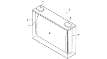
- FIG. 1 is an external perspective view showing a non-aqueous electrolyte storage element according to an embodiment of the present invention.
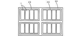
- FIG. 2 is a schematic view showing a power storage device configured by assembling a plurality of non-aqueous electrolyte power storage elements according to an embodiment of the present invention.
- a non-aqueous electrolyte storage device includes a positive electrode having a positive electrode mixture containing a phosphorus atom and a non-aqueous electrolyte containing an imide salt, in the X-ray photoelectron spectrum of the positive electrode mixture. It is a non-aqueous electrolyte storage element in which the peak attributed to P2p is present at a position of 135 eV or less.
- the oxidation corrosion of aluminum can be suppressed without increasing the concentration of the imide salt in the non-aqueous electrolyte, and an increase in internal resistance after charge and discharge cycles can be suppressed.
- the reason which the said effect produces in the said non-aqueous electrolyte electrical storage element is not certain, the following reasons are assumed.
- the non-aqueous electrolyte storage element has a high concentration of imide salt, which can improve the undesirable point of the non-aqueous electrolyte storage element using high concentration imide salt, such as conventional viscosity and high internal resistance. It can be suitably used as a range design.
- the sample (positive electrode compound material) used for the measurement of a X-ray-photoelectron-spectroscopy spectrum is prepared by the following method.
- the non-aqueous electrolyte storage element is discharged at a current of 0.1 C to a discharge termination voltage during normal use to bring it into a completely discharged state.
- the storage element in a completely discharged state is disassembled, the positive electrode is taken out, and after sufficiently washing the positive electrode with dimethyl carbonate, drying under reduced pressure is performed at room temperature.
- the dried positive electrode is cut out into a predetermined size (for example, 2 ⁇ 2 cm), which is used as a sample in measurement of an X-ray photoelectron spectrum.
- the work from disassembly of the non-aqueous electrolyte storage element to preparation of the sample in measurement of X-ray photoelectron spectroscopy is performed in an argon atmosphere with a dew point of -60 ° C or less, and the prepared sample is sealed in a transfer vessel
- the sample is held in an argon atmosphere at ⁇ ° C. and introduced into a sample chamber of an X-ray photoelectron spectrum measuring apparatus.
- the apparatus used and the measurement conditions in the measurement of an X-ray photoelectron spectrum are as follows.
- the position of the peak in the spectrum is a value obtained as follows. First, the position of the C1s peak assigned to the sp2 carbon is set to 284.8 eV, and the binding energies of all the obtained spectra are corrected. Next, the corrected spectrum is leveled by removing the background using the linear method. In the spectrum after leveling treatment, the binding energy at which the peak intensity attributable to P2p exhibits the highest value is taken as the position of the peak attributable to P2p.
- content of the said imide salt in the said nonaqueous electrolyte is 0.5 mol / kg or more and 2 mol / kg or less.
- content of the said imide salt in the said nonaqueous electrolyte is 0.5 mol / kg or more and 2 mol / kg or less.
- the internal resistance does not increase by setting the concentration of the imide salt in the non-aqueous electrolyte to a concentration range not high as in the above range, and after charge and discharge cycles. Rise in internal resistance can be suppressed. Furthermore, since the viscosity of the non-aqueous electrolyte containing an imido salt in a concentration range that is not a high concentration as described above is low, it is expected to enhance high-rate discharge performance and the like at low temperatures.
- the maximum ultimate potential of the positive electrode is preferably 4.4 V (vs. Li / Li + ) or more, and 4.5 V (vs. Li / Li + ) or more More preferably, it is more preferably 4.6 V (vs. Li / Li + ) or more.
- the non-aqueous electrolyte storage element usually, when the imide salt is used, charge and discharge in which the maximum ultimate potential of the positive electrode which is likely to cause remarkable oxidation corrosion of aluminum is 4.4 V (vs. Li / Li + ) or more Also in the above, the internal resistance after the charge and discharge cycle can be reduced. Therefore, by setting the maximum ultimate potential of the positive electrode to 4.4 V (vs. Li / Li + ) or more, the positive electrode can be 4.4 V (vs. Li / Li) while suppressing an increase in internal resistance after charge and discharge cycles. + ) Capacitance can be increased by charging and discharging at the above operating potential.
- a method of manufacturing a non-aqueous electrolyte storage device comprising: a positive electrode having a positive electrode mixture produced using a positive electrode mixture paste containing oxo acid of phosphorus; A method of manufacturing a non-aqueous electrolyte storage element using the
- a positive electrode mixture paste containing an oxo acid of phosphorus By using a positive electrode mixture paste containing an oxo acid of phosphorus, a positive electrode mixture in which a peak attributed to P2p is present at a position of 135 eV or less in the X-ray photoelectron spectroscopy spectrum can be obtained. Therefore, according to the said manufacturing method, even if it is using the imide salt of the density
- non-aqueous electrolyte storage device according to an embodiment of the present invention and a method of manufacturing the non-aqueous electrolyte storage device will be described in detail.
- a non-aqueous electrolyte storage device includes a positive electrode, a negative electrode, and a non-aqueous electrolyte.
- a non-aqueous electrolyte secondary battery will be described as an example of the non-aqueous electrolyte storage element.
- the positive electrode and the negative electrode usually form an electrode body alternately stacked or wound via a separator.
- the electrode body is housed in a container, and the container is filled with the non-aqueous electrolyte.
- the non-aqueous electrolyte is interposed between the positive electrode and the negative electrode.
- the well-known metal container normally used as a container of a nonaqueous electrolyte secondary battery, a resin container etc. can be used.
- the positive electrode has a positive electrode base material, and a positive electrode mixture layer disposed directly or via an intermediate layer on the positive electrode base material.
- the said positive electrode base material has electroconductivity.
- a material of a base material metals, such as aluminum, titanium, a tantalum, stainless steel, or those alloys are used. Among these, aluminum and aluminum alloys are preferable in terms of the balance of conductivity height and cost.
- the positive electrode substrate is aluminum or an aluminum alloy, the effect of suppressing the increase in internal resistance after charge and discharge cycles of the non-aqueous electrolyte storage element, which is presumed to be mainly caused by the oxidation corrosion of aluminum, is more sufficient.
- a foil is preferable. That is, an aluminum foil is preferable as the positive electrode substrate.
- A1085P, A3003P, etc. defined in JIS-H-4000 (2014) can be exemplified.
- the intermediate layer is a coating layer on the surface of the positive electrode base material, and reduces the contact resistance between the positive electrode base material and the positive electrode mixture layer by containing conductive particles such as carbon particles.
- the configuration of the intermediate layer is not particularly limited, and can be formed of, for example, a composition containing a resin binder and conductive particles.
- having "conductivity” means that the volume resistivity measured based on JIS-H-0505 (1975) is 10 7 ohm-cm or less, and "non-conductivity” Means that the above-mentioned volume resistivity is more than 10 7 ⁇ ⁇ cm.
- the positive electrode mixture layer is a layer formed of a positive electrode mixture.
- the positive electrode mixture contains a positive electrode active material and a phosphorus atom, and further contains optional components such as a conductive agent, a binder, a thickener, a filler, a dispersant and the like as required. In the X-ray photoelectron spectrum of the positive electrode mixture, the peak attributed to P2p is present at a position of 135 eV or less.
- the positive electrode mixture layer is usually formed on the surface of the positive electrode base material by coating and drying a positive electrode mixture paste containing a positive electrode active material, phosphorus oxo acid and the like.
- the non-aqueous electrolyte storage element part or all of the oxo acid of phosphorus may be denatured. Moreover, it is estimated that the said phosphorus atom exists in the film formed in the positive electrode compound surface. That is, the presence of the phosphorus atom derived from the oxo acid of phosphorus in the film formed on the surface of the positive electrode mixture causes the peak belonging to P2p to be 135 eV or less in the X-ray photoelectron spectrum of the positive electrode mixture. It is presumed to be present at the position.
- Examples of the positive electrode active material include lithium transition metal complex oxides and polyanion compounds.
- a lithium transition metal complex oxide for example, a complex oxide represented by Li x MO y (M represents at least one transition metal) (Li x CoO 2 , Li having a layered ⁇ -NaFeO 2 type crystal structure) x NiO 2 , Li x MnO 3 , Li x Ni ⁇ Co (1- ⁇ ) O 2 , Li x Ni ⁇ Co ⁇ Al (1- ⁇ - ⁇ ) O 2 , Li x Ni ⁇ Mn ⁇ Co (1- ⁇ - ⁇ ) O 2 , Li 1 + x (Ni ⁇ Mn ⁇ Co (1- ⁇ - ⁇ ) ) 1-x O 2 , etc., Li x Mn 2 O 4 having a spinel crystal structure, Li x Ni ⁇ Mn (2- ⁇ ) O 4 , etc.).
- a polyanion compound represented by Li w M x (XO y ) z (Me represents at least one transition metal and X represents, for example, P, Si, B, V, etc.) , LiMnPO 4 , LiNiPO 4 , LiCoPO 4 , Li 3 V 2 (PO 4 ) 3 , Li 2 MnSiO 4 , Li 2 CoPO 4 F, and the like.
- the elements or polyanions in these compounds may be partially substituted with other element or anion species.
- one of these compounds may be used alone, or two or more thereof may be mixed and used.
- the said positive electrode active material contains the positive electrode active material which can become nobler than 4.0 V (vs. Li / Li ⁇ +> ) in the positive electrode potential in the charge final voltage at the time of normal use of a nonaqueous electrolyte electrical storage element.
- a positive electrode active material lithium transition metal complex oxide is preferable.
- the non-aqueous electrolyte storage element suppresses an increase in internal resistance after charge and discharge cycles. Therefore, by using a positive electrode active material that can have a positive electrode operating potential of 4.0 V (vs.
- the normal use time refers to the case where the non-aqueous electrolyte storage element is used by adopting the charge / discharge condition recommended or specified in the non-aqueous electrolyte storage element.
- the time of normal use when a charger for the non-aqueous electrolyte storage element is prepared, the case where the non-aqueous electrolyte storage element is used by applying the charger is usually referred to as the time of normal use.
- the positive electrode active material may be substantially constituted only of the lithium transition metal complex oxide.
- the positive electrode active material more preferably includes a positive electrode active material which can have a positive electrode operating potential of 4.4 V (vs. Li / Li + ) or more at a charge termination voltage during normal use of the non-aqueous electrolyte storage element.
- the positive electrode active material which can have a positive electrode operating potential of 4.4 V (vs. Li / Li + ) or more at the charge end voltage in normal use is reversible at a potential of 4.4 V (vs. Li / Li + ) or more It may be a positive electrode active material capable of inserting and releasing lithium ions.
- the content of the positive electrode active material in the positive electrode mixture layer can be, for example, 80% by mass or more and 98% by mass or less, and preferably 90% by mass or more.
- the upper limit of the position of the peak attributed to P2p is preferably 134 eV.
- the lower limit of the position of this peak may be 130 eV or 132 eV.
- the conductive agent is not particularly limited as long as the conductive material does not adversely affect the performance of the storage element.
- examples of such conductive agents include natural or artificial graphite, carbon blacks such as furnace black, acetylene black and ketjen black, metals, conductive ceramics and the like, with acetylene black being preferred.
- the shape of the conductive agent may, for example, be powdery or fibrous.
- binder examples include thermoplastic resins such as fluororesin (polytetrafluoroethylene (PTFE), polyvinylidene fluoride (PVDF), etc.), polyethylene, polypropylene, polyimide, etc .; ethylene-propylene-diene rubber (EPDM), sulfonated EPDM, styrene Elastomers such as butadiene rubber (SBR) and fluororubber; polysaccharide polymers etc. may be mentioned.
- thermoplastic resins such as fluororesin (polytetrafluoroethylene (PTFE), polyvinylidene fluoride (PVDF), etc.), polyethylene, polypropylene, polyimide, etc .
- EPDM ethylene-propylene-diene rubber
- SBR butadiene rubber
- fluororubber polysaccharide polymers etc.
- the thickener examples include polysaccharide polymers such as carboxymethylcellulose (CMC) and methylcellulose.
- CMC carboxymethylcellulose
- methylcellulose a functional group that reacts with lithium
- the filler is not particularly limited as long as it does not adversely affect the performance of the storage element.
- the main component of the filler include polyolefins such as polypropylene and polyethylene, silica, alumina, zeolite, glass and the like.
- the negative electrode has a negative electrode base material, and a negative electrode composite layer disposed directly or via an intermediate layer on the negative electrode base material.
- the intermediate layer may have the same configuration as the intermediate layer of the positive electrode.
- the above-mentioned negative electrode substrate can be made to have the same configuration as the positive electrode substrate, but as materials, metals such as copper, nickel, stainless steel, nickel plated steel or alloys thereof are used, and copper or copper alloy preferable. That is, copper foil is preferable as the negative electrode substrate. As a copper foil, a rolled copper foil, an electrolytic copper foil, etc. are illustrated.
- the negative electrode mixture layer is formed of a negative electrode mixture containing a negative electrode active material.
- the negative electrode composite material which forms a negative electrode composite material layer contains arbitrary components, such as a electrically conductive agent, a binder, a thickener, a filler, a dispersing agent, as needed.
- the optional components such as the conductive agent, the binder, the thickener, the filler, and the dispersant, the same components as those of the positive electrode mixture layer can be used.
- negative electrode active material usually, a material capable of inserting and extracting lithium ions and the like is used.
- specific examples of negative electrode active materials include metals or metalloids such as Si and Sn; metal oxides or metalloid oxides such as Si oxide and Sn oxide; polyphosphate compounds; graphite (graphite), non-graphitic Carbon materials such as carbon (graphitizable carbon or non-graphitizable carbon) and the like can be mentioned.
- the negative electrode composite material (negative electrode composite material layer) is typically non-metallic elements such as B, N, P, F, Cl, Br, I, etc., Li, Na, Mg, Al, K, Ca, Zn, Ga, Ge And other transition metal elements such as Sc, Ti, V, Cr, Mn, Fe, Co, Ni, Cu, Mo, Zr, Ta, Hf, Nb, W and the like.
- a woven fabric, a nonwoven fabric, a porous resin film etc. are used, for example.
- a porous resin film is preferable from the viewpoint of strength
- a nonwoven fabric is preferable from the viewpoint of liquid retention of the non-aqueous electrolyte.
- polyolefins such as polyethylene and polypropylene are preferable from the viewpoint of strength
- polyimide and aramid are preferable from the viewpoint of resistance to oxidative degradation.
- these resins may be composited.
- An inorganic insulator layer may be disposed between the separator and the electrode (usually, the positive electrode).
- This inorganic insulator layer is a porous layer also called a heat-resistant layer or the like.
- the separator in which the inorganic insulating material layer was formed in the one or both surfaces of a porous resin film can also be used.
- the inorganic insulator layer is usually composed of inorganic insulator particles and a binder, and may contain other components.
- As the inorganic insulator particles Al 2 O 3 , SiO 2 , aluminosilicate and the like are preferable.
- Non-aqueous electrolyte comprises an imide salt and a non-aqueous solvent in which the imide salt is dissolved.
- the said non-aqueous electrolyte is not limited to a liquid thing. That is, the non-aqueous electrolyte also includes solid, gel and the like.
- imide salt examples include lithium imide salt, sodium imide salt, potassium imide salt and the like, with preference given to lithium imide salt.
- LiN (SO 2 F) 2 lithium bis (fluorosulfonyl) imide: LiFSI
- LiN (CF 3 SO 2) 2 lithium bis (trifluoromethanesulfonyl) imide: LiTFSI
- LiN (C 2 F 5 SO 2) 2 Lithium bis (pentafluoroethanesulfonyl) imide: LiBETI
- LiN (C 4 F 9 SO 2 ) 2 lithium bis (nonafluorobutanesulfonyl) imide
- the lithium imide salt preferably has a fluorine atom, and specifically preferably has, for example, a fluorosulfonyl group, a difluorophosphonyl group, a fluoroalkyl group and the like.
- lithium imide salts lithium sulfonylimide salts are preferable, LiFSI, LiTFSI and LiBETI are more preferable, and LiFSI is more preferable.
- These imide salts are imide salts which relatively easily cause oxidation corrosion of aluminum during charge and discharge when the working potential of the positive electrode is 4.0 V (vs. Li / Li + ) or more.
- the lower limit of the content of the imide salt in the non-aqueous electrolyte is, for example, preferably 0.5 mol / kg, more preferably 0.8 mol / kg.
- the upper limit of the content is preferably 2 mol / kg, more preferably 1.4 mol / kg, still more preferably 1.2 mol / kg, and even more preferably 1.1 mol / kg.
- the non-aqueous electrolyte may further contain or may not contain an electrolyte salt other than the imide salt.
- electrolyte salts include lithium salts other than imide salts, sodium salts, potassium salts, magnesium salts, onium salts and the like.
- the upper limit of the content of the electrolyte salt other than the imide salt in the non-aqueous electrolyte is preferably 1 mol / kg, and more preferably 0.1 mol / kg. And 0.01 mol / kg may be more preferable.
- the electrolyte salt other than the imide salt can be a electrolyte salt having a PF 6 anions such LiPF 6.
- the peak attributed to P2p derived from LiPF 6 is a position exceeding 135 eV (usually more than 135 eV and 138 eV or less In the range of Therefore, the peak attributed to P2p derived from LiPF 6 can be distinguished from the peak attributed to P2p derived from the oxo acid of phosphorus based on the difference in peak position.
- Non-aqueous solvent As said non-aqueous solvent, the well-known non-aqueous solvent generally used can be used as a non-aqueous solvent of general nonaqueous electrolyte for electrical storage elements.
- the non-aqueous solvent include carbonates (cyclic carbonates and chain carbonates), esters, ethers, amides, sulfones, lactones, nitriles and the like. Among these, it is preferable to use at least a carbonate, and it is more preferable to use a cyclic carbonate and a linear carbonate in combination.
- the carbonate may be a carbonate having no substituent or may be a carbonate having a substituent. Examples of this substituent include a hydroxy group and a halogen atom.
- the volume ratio of cyclic carbonate and chain carbonate is not particularly limited, but for example, 5: 95 or more and 50: 50 or less Is preferred.
- the lower limit of the content of the cyclic carbonate in the non-aqueous solvent is preferably 1% by volume, more preferably 5% by volume.
- 50 volume% is preferable and 40 volume% is more preferable.
- the lower limit of the content of the linear carbonate in the non-aqueous solvent is preferably 20% by volume, and more preferably 50% by volume.
- 95 volume% is preferable and 90 volume% is more preferable.
- cyclic carbonate examples include ethylene carbonate (EC), propylene carbonate (PC), butylene carbonate (BC), vinylene carbonate (VC), vinyl ethylene carbonate (VEC), chloroethylene carbonate, fluoroethylene carbonate (FEC), difluoroethylene Carbonate (DFEC), fluoromethyl ethylene carbonate, trifluoroethyl ethylene carbonate, styrene carbonate, catechol carbonate, 1-phenylvinylene carbonate, 1,2-diphenylvinylene carbonate and the like can be mentioned.
- chain carbonate examples include diethyl carbonate (DEC), dimethyl carbonate (DMC), ethyl methyl carbonate (EMC), diphenyl carbonate, methyl trifluoroethyl carbonate (MFEC), bis (trifluoroethyl) carbonate (FDEC) and the like. It can be mentioned.
- the non-aqueous solvent preferably contains a fluorinated carbonate.
- the cyclic carbonate is preferably a fluorinated cyclic carbonate such as fluoroethylene carbonate, difluoroethylene carbonate, fluoromethyl ethylene carbonate, trifluoroethyl ethylene carbonate and the like.
- the chain carbonate is preferably a fluorinated chain carbonate such as methyl trifluoroethyl carbonate or bis (trifluoroethyl) carbonate.
- fluorinated carbonate suppresses side reactions at a potential of 4.0 V (vs. Li / Li + ) or more, suppresses the increase in internal resistance after charge and discharge cycles, improves the capacity retention rate, and the like. Performance can be further improved.
- fluorinated solvents other than fluorinated carbonate can be used.
- fluorinated solvents 1,1,2,2-tetrafluoroethyl-2,2,3,3-tetrafluoropropyl ether, 1,1,2,2-tetrafluoroethyl-2,2,2
- fluorinated ethers such as 2-trifluoroethyl ether (TFEE) and the like.
- the lower limit of the total content of the fluorinated solvent in the non-aqueous solvent is preferably 20% by volume, more preferably 50% by volume, still more preferably 80% by volume, and still more preferably 90% by volume. Volume% is even more preferred.
- the internal resistance increases after the charge and discharge cycle at a potential of 4.0 V (vs. Li / Li + ) or more. Can be effectively suppressed, and the capacity retention rate can be further enhanced.
- the upper limit of the content of components other than the non-aqueous solvent and the electrolyte salt containing the imide salt in the non-aqueous electrolyte may be preferably 5% by mass, and 1% by mass may be more preferable. .1 wt% may be more preferred.
- the lower limit of the maximum ultimate potential of the positive electrode of the non-aqueous electrolyte storage element may be, for example, 4.0 V (vs. Li / Li + ) or 4.2 V (vs. Li / Li + ), but 4.4 V (Vs. Li / Li + ) is preferable, 4.5 V (vs.
- Li / Li + is more preferable, 4.6 V (vs. Li / Li + ) is more preferable, 4.7 V (vs. Li / Li) + ) Is even more preferred.
- the upper limit of the maximum achieved potential of the positive electrode is, for example, 5.4V (vs.Li/Li +), may be 5.0V (vs.Li/Li +).
- the maximum ultimate potential of the positive electrode is preferably the positive electrode potential at the charge termination voltage of the non-aqueous electrolyte storage element during normal use.
- the maximum ultimate potential of the positive electrode frequently becomes, for example, 4.4 V (vs. Li / Li + ) or more due to repeated charge and discharge, increase in internal resistance after charge and discharge cycle of the non-aqueous electrolyte storage element The suppression effect and the improvement effect of the capacity retention rate are more pronounced.
- a method of manufacturing a non-aqueous electrolyte storage device includes: a positive electrode having a positive electrode mixture produced using a positive electrode mixture paste containing an oxo acid of phosphorus; It is a manufacturing method of the nonaqueous electrolyte electrical storage element using electrolyte.
- non-aqueous electrolyte storage element Manufacturing a positive electrode using a positive electrode mixture paste containing phosphorus oxo acid (positive electrode preparation step); Injecting the non-aqueous electrolyte containing the imide salt into the container (non-aqueous electrolyte injection step).
- the positive electrode mixture paste usually contains, in addition to phosphorus oxo acid, a positive electrode active material and a binder, and further contains other components as necessary.
- the positive electrode mixture paste can be obtained by mixing these components.
- the positive electrode mixture paste is applied to the surface of the positive electrode substrate and dried to obtain a positive electrode having a peak attributed to P2p of 135 eV or less in the X-ray photoelectron spectrum of the positive electrode mixture.
- the oxo acids of phosphorus include phosphoric acid (H 3 PO 4 ), phosphonic acid (H 3 PO 3 ), phosphinic acid (H 3 PO 2 ), pyrophosphoric acid (H 4 P 2 O 7 ), polyphosphoric acid and the like. It can be mentioned. Among these, phosphoric acid and phosphonic acid are preferable, and phosphonic acid is more preferable.
- a film containing a phosphorus atom is formed on the positive electrode by the phosphorus oxo acid, and a positive electrode having a peak attributed to P2p at a position of 135 eV or less in the X-ray photoelectron spectrum of the positive electrode mixture is obtained.
- phosphorus oxo acid instead of phosphorus oxo acid, metal salt of oxo acid of phosphorus (lithium salt, sodium salt, potassium salt, magnesium salt, calcium salt etc.) or ester of phosphorus oxo acid (phosphate ester, phosphonate ester etc.) is used. Also, in the X-ray photoelectron spectrum of the positive electrode mixture, the positive electrode in which the peak attributed to P2p is present at a position of 135 eV or less can not be obtained, and the effect of the present invention is not exhibited.
- metal salt of oxo acid of phosphorus lithium salt, sodium salt, potassium salt, magnesium salt, calcium salt etc.
- ester of phosphorus oxo acid phosphate ester, phosphonate ester etc.
- the lower limit of the oxo acid content (addition amount) of phosphorus in the positive electrode mixture paste is preferably 0.05 parts by mass, more preferably 0.1 parts by mass, with respect to 100 parts by mass of the positive electrode active material. .3 parts by weight is more preferred. On the other hand, as an upper limit of this content, 5 mass parts is preferred, 3 mass parts is more preferred, and 2 mass parts is still more preferred.
- an organic solvent is usually used as a dispersion medium.
- the organic solvent include polar solvents such as N-methyl-2-pyrrolidone (NMP), acetone and ethanol, and nonpolar solvents such as xylene, toluene and cyclohexane.
- Non-aqueous electrolyte injection process The non-aqueous electrolyte injection step can be performed by a known method. That is, a non-aqueous electrolyte having a desired composition may be prepared, and the prepared non-aqueous electrolyte may be injected into the container.
- the said manufacturing method may have the following processes other than the said positive electrode preparation process and the non-aqueous electrolyte injection process. That is, the manufacturing method includes, for example, a step of manufacturing a negative electrode, a step of forming an electrode body alternately stacked by winding or winding a positive electrode and a negative electrode through a separator, and a positive electrode and a negative electrode ) Can be included in the container. Usually, after the electrode body is housed in the container, the non-aqueous electrolyte is injected into the container, but the order may be reversed. After these steps, the non-aqueous electrolyte storage element can be obtained by sealing the inlet.
- the present invention is not limited to the above embodiment, and can be implemented in various modifications and improvements in addition to the above embodiment.
- the intermediate layer may not be provided in the positive electrode or the negative electrode.
- the positive electrode mixture may not form a clear layer.
- the positive electrode may have a structure in which a positive electrode mixture is supported on a mesh-like positive electrode base material.
- non-aqueous electrolyte electrical storage element demonstrated mainly on the form which is a non-aqueous electrolyte secondary battery
- another nonaqueous electrolyte electrical storage element may be sufficient.
- other non-aqueous electrolyte storage elements include capacitors (electric double layer capacitors, lithium ion capacitors) and the like.
- FIG. 1 is a schematic view of a rectangular non-aqueous electrolyte storage element 1 which is an embodiment of the non-aqueous electrolyte storage element according to the present invention.
- the same figure is a view seen through the inside of the container.
- the electrode body 2 is housed in the container 3.
- the electrode body 2 is formed by winding a positive electrode including a positive electrode mixture and a negative electrode including the negative electrode mixture via a separator.
- the positive electrode is electrically connected to the positive electrode terminal 4 via the positive electrode lead 4 ′
- the negative electrode is electrically connected to the negative electrode terminal 5 via the negative electrode lead 5 ′.
- a non-aqueous electrolyte is injected into the container 3.
- the configuration of the non-aqueous electrolyte storage element according to the present invention is not particularly limited, and a cylindrical battery, a rectangular battery (rectangular battery), a flat battery and the like can be mentioned as an example.
- the present invention can also be realized as a power storage device provided with a plurality of the above non-aqueous electrolyte power storage elements.
- a power storage device is shown in FIG. In FIG. 2, power storage device 30 includes a plurality of power storage units 20. Each storage unit 20 includes a plurality of non-aqueous electrolyte storage elements 1.
- the power storage device 30 can be mounted as a power source for vehicles such as an electric vehicle (EV), a hybrid vehicle (HEV), and a plug-in hybrid vehicle (PHEV).
- EV electric vehicle
- HEV hybrid vehicle
- PHEV plug-in hybrid vehicle
- Lithium transition metal complex oxide having an ⁇ -NaFeO 2 structure and represented by Li 1+ ⁇ Me 1 - ⁇ O 2 as a positive electrode active material (Me is a transition metal containing Mn, 0.1 ⁇ ⁇ 0.2 The molar ratio of Mn to Me, Mn / Me was 0.5 ⁇ Mn / Me).
- NMP N-methyl pyrrolidone
- AB acetylene black
- PVDF polyvinylidene fluoride
- H 3 PO 3 phosphonic acid
- the positive mix paste was similarly apply
- the positive electrode mixture layer formed on the opposite surface was peeled after drying. Thus, the positive electrode P1 was obtained.
- a positive electrode R1 was obtained in the same manner as the above-mentioned "preparation of positive electrode P1" except that phosphonic acid was not mixed in the positive electrode mixture paste.
- a lithium transition metal complex oxide having an ⁇ -NaFeO 2 structure and represented by LiNi 1/3 Co 1/3 Mn 1/3 O 2 was used as a positive electrode active material.
- N-methyl pyrrolidone (NMP) is used as a dispersion medium, and the above positive electrode active material, acetylene black (AB) as a conductive agent, polyvinylidene fluoride (PVDF) as a binder, and phosphonic acid (H 3 PO 3 ) It mixed by the mass ratio of 95.5: 2: 2: 0.5 in conversion, and obtained the positive mix paste.
- the positive electrode mixture paste was applied to one surface of an aluminum foil as a positive electrode substrate, and dried by heating at 100 ° C.
- the positive mix paste was similarly apply
- the positive electrode mixture layer formed on the opposite surface was peeled after drying. Thus, the positive electrode P2 was obtained.
- a positive electrode R2 was obtained in the same manner as the above-mentioned "preparation of positive electrode P2" except that phosphonic acid was not mixed in the positive electrode mixture paste.
- a positive electrode R3 was obtained in the same manner as the above-mentioned "preparation of positive electrode P3" except that phosphonic acid was not mixed in the positive electrode mixture paste.
- Example 1 Preparation of non-aqueous electrolyte
- FEC fluoroethylene carbonate
- MFEC methyl trifluoroethyl carbonate
- LiFSI lithium bis (fluorosulfonyl) imide
- An electrode body was produced by laminating the positive electrode P1 and the negative electrode via a separator which is a polyolefin microporous film. This electrode body is housed in a container made of a metal resin composite film, and after injecting the non-aqueous electrolyte into the inside, the electrode is sealed by heat welding, and the non-aqueous electrolyte storage element of Example 1 (laminate type non-aqueous electrolyte secondary) Battery).
- Example 2 to 6 Comparative Examples 1 to 6, Reference Examples 1 to 2
- Examples 2 to 6, Comparative Examples 1 to 6 and Reference were carried out in the same manner as Example 1, except that the types of positive electrode and electrolyte salt, and the type and mixing volume ratio of solvents were as shown in Tables 1 to 3.
- the nonaqueous electrolyte storage elements of Examples 1 and 2 were obtained.
- the peak attributed to P2p was present between 133 and 134 eV.
- the positive electrode composite materials (R1) of Comparative Examples 1 to 4 and Reference Example 2 in which no phosphonic acid was used a peak attributed to P2p was not confirmed in the range of 135 eV or less.
- a peak attributed to P2p derived from LiPF 6 could be confirmed at 136 eV.
- the internal resistance (ACR) of each of the non-aqueous electrolyte storage devices before and after the charge-discharge cycle test was measured by an alternating current (1 kHz) method.
- the ratio of the internal resistance (ACR) after the charge and discharge cycle test to the internal resistance (ACR) before the above charge and discharge cycle test is shown in Table 1 as an ACR ratio.
- Capacity maintenance rate The discharge capacity of the 50th cycle with respect to the discharge capacity of the 1st cycle of the above-mentioned charge and discharge cycle test is shown in Table 1 as a capacity retention ratio (%) for each nonaqueous electrolyte storage element.
- the internal resistance is not smaller after the charge and discharge cycle than before the charge and discharge cycle, and the increase in the internal resistance associated with the charge and discharge cycle is suppressed.
- the positive electrode P1 in which the peak attributed to P2p is at a position of 135 eV or less the effect that the ACR ratio is small and the increase in internal resistance after charge and discharge cycles is suppressed is exhibited remarkably You see (see Table 1).
- the effect of suppressing an increase in internal resistance after charge and discharge cycles is imide salt as an electrolyte salt, and a positive electrode having a peak attributed to P2p at a position of 135 eV or less in the X-ray photoelectron spectrum of the positive electrode mixture. It can be said that this is a unique effect that occurs for the first time in combination with P1 to P3.
- Example 1 in the case of the positive electrode P1 having a peak attributed to P2p in the position of 135 eV or less in the X-ray photoelectron spectrum of the positive electrode mixture, the electrolyte salt is LiPF
- 6 Reference Example 1
- the imide salt Comparative Example 1
- the ACR ratio decreased, and the increase in internal resistance after charge and discharge cycles was conversely suppressed.
- the positive electrode having a peak attributed to P2p of 135 eV or less in the X-ray photoelectron spectroscopy spectrum of the positive electrode mixture it is considered that it is likely to cause oxidation corrosion of aluminum as an electrolyte salt.
- the effect that the rise of the internal resistance after the charge and discharge cycle is conversely suppressed by using the imide salt mentioned above can be said to be a unique effect which could not be predicted at all from the conventional findings.
- Capacity maintenance rate Focusing on the capacity retention rate after charge and discharge cycles, as can be seen from the comparison between Example 1 and Reference Example 1 in Table 1, the peak attributed to P2p is 135 eV or less in the X-ray photoelectron spectrum of the positive electrode composite.
- the capacity retention rate after the charge and discharge cycle is improved by using the imide salt as the electrolyte salt.
- Comparative Example 1 and Reference Example 2 when using the conventional positive electrode R1, the electrolyte salt was changed from LiPF 6 (Reference Example 1) to the imide salt (Example 1), as in the conventional findings. ), The capacity retention rate after the charge and discharge cycle decreases.
- the positive electrode P1 having a peak attributed to P2p of 135 eV or less in the X-ray photoelectron spectrum of the positive electrode mixture it is considered that it is easy to cause oxidation corrosion of aluminum as an electrolyte salt.
- the imide salt By using the imide salt, the effect of improving the capacity retention rate after charge and discharge cycles can be said to be a unique effect that can not be predicted from conventional findings.
- the present invention is applicable to electronic devices such as personal computers and communication terminals, non-aqueous electrolyte storage devices used as power sources for automobiles and the like.
Landscapes
- Chemical & Material Sciences (AREA)
- Chemical Kinetics & Catalysis (AREA)
- Electrochemistry (AREA)
- General Chemical & Material Sciences (AREA)
- Engineering & Computer Science (AREA)
- Materials Engineering (AREA)
- Manufacturing & Machinery (AREA)
- Inorganic Chemistry (AREA)
- Composite Materials (AREA)
- Condensed Matter Physics & Semiconductors (AREA)
- General Physics & Mathematics (AREA)
- Physics & Mathematics (AREA)
- Secondary Cells (AREA)
- Battery Electrode And Active Subsutance (AREA)
- Electric Double-Layer Capacitors Or The Like (AREA)
- Cell Electrode Carriers And Collectors (AREA)
Abstract
Description
装置:KRATOS ANALYTICAL社の「AXIS NOVA」
X線源:単色化AlKα
加速電圧:15kV
分析面積:700μm×300μm
測定範囲:P2p=145~128eV、C1s=300~272eV
測定間隔:0.1eV
測定時間:P2p=72.3秒/回、C1s=70.0秒/回
積算回数:P2p=15回、C1s=8回
本発明の一実施形態に係る非水電解質蓄電素子は、正極、負極及び非水電解質を有する。以下、非水電解質蓄電素子の一例として、非水電解質二次電池について説明する。上記正極及び負極は、通常、セパレータを介して積層又は巻回により交互に重畳された電極体を形成する。この電極体は容器に収納され、この容器内に上記非水電解質が充填される。上記非水電解質は、正極と負極との間に介在する。また、上記容器としては、非水電解質二次電池の容器として通常用いられる公知の金属容器、樹脂容器等を用いることができる。
上記正極は、正極基材、及びこの正極基材に直接又は中間層を介して配される正極合材層を有する。
上記負極は、負極基材、及びこの負極基材に直接又は中間層を介して配される負極合材層を有する。上記中間層は正極の中間層と同様の構成とすることができる。
上記セパレータの材質としては、例えば織布、不織布、多孔質樹脂フィルム等が用いられる。これらの中でも、強度の観点から多孔質樹脂フィルムが好ましく、非水電解質の保液性の観点から不織布が好ましい。上記セパレータの主成分としては、強度の観点から例えばポリエチレン、ポリプロピレン等のポリオレフィンが好ましく、耐酸化分解性の観点から例えばポリイミドやアラミド等が好ましい。また、これらの樹脂を複合してもよい。
上記非水電解質は、イミド塩と、このイミド塩を溶解している非水溶媒を含む。なお、上記非水電解質は、液体状のものに限定されるものではない。すなわち、上記非水電解質は、固体状やゲル状のもの等も含まれる。
イミド塩としては、リチウムイミド塩、ナトリウムイミド塩、カリウムイミド塩等を挙げることができるが、リチウムイミド塩が好ましい。
LiN(SO2F)2(リチウムビス(フルオロスルホニル)イミド:LiFSI)、LiN(CF3SO2)2(リチウムビス(トリフルオロメタンスルホニル)イミド:LiTFSI)、LiN(C2F5SO2)2(リチウムビス(ペンタフルオロエタンスルホニル)イミド:LiBETI)、LiN(C4F9SO2)2(リチウムビス(ノナフルオロブタンスルホニル)イミド)、CF3-SO2-N-SO2-N-SO2CF3Li、FSO2-N-SO2-C4F9Li、CF3-SO2-N-SO2-C4F9Li、CF3-SO2-N-SO2-CF2-SO2-N-SO2-CF3Li2、CF3-SO2-N-SO2-CF2-SO3Li2、CF3-SO2-N-SO2-CF2-SO2-C(-SO2CF3)2Li2等のリチウムスルホニルイミド塩;
LiN(POF2)2(リチウムビス(ジフルオロホスホニル)イミド:LiDFPI)等のリチウムホスホニルイミド塩等を挙げることができる。リチウムイミド塩は、1種又は2種以上を用いることができる。
上記非水電解質には、上記イミド塩以外の電解質塩がさらに含有されていてもよいし、含有されていなくてもよい。このような電解質塩としては、イミド塩以外のリチウム塩、ナトリウム塩、カリウム塩、マグネシウム塩、オニウム塩等を挙げることができる。イミド塩以外の電解質塩が含有されている場合、上記非水電解質におけるイミド塩以外の電解質塩の含有量の上限としては、1mol/kgが好ましいことがあり、0.1mol/kgがより好ましいことがあり、0.01mol/kgがさらに好ましいことがある。イミド塩以外の電解質塩の含有量を上記上限以下とすることで、充放電サイクル後の内部抵抗の上昇を効果的に抑制でき、容量維持率をより高めることができる。上記非水電解質におけるイミド塩以外の電解質塩の含有量の上限が0.01mol/kgである場合、上記非水電解質はイミド塩以外の電解質塩を実質的に含有しないに等しい。上記イミド塩以外の電解質塩は、LiPF6等のPF6アニオンを有する電解質塩であってよい。
上記非水溶媒としては、一般的な蓄電素子用非水電解質の非水溶媒として通常用いられる公知の非水溶媒を用いることができる。上記非水溶媒としては、カーボネート(環状カーボネート及び鎖状カーボネート)、エステル、エーテル、アミド、スルホン、ラクトン、ニトリル等を挙げることができる。これらの中でも、カーボネートを少なくとも用いることが好ましく、環状カーボネートと鎖状カーボネートとを併用することがより好ましい。なお、カーボネートは、置換基を有さないカーボネートであってもよく、置換基を有するカーボネートであってもよい。この置換基としては、ヒドロキシ基、ハロゲン原子等を挙げることができる。
当該非水電解質蓄電素子は、以下の方法により製造することが好ましい。すなわち、本発明の一実施形態に係る非水電解質蓄電素子の製造方法は、リンのオキソ酸を含む正極合材ペーストを用いて作製される正極合材を有する正極と、イミド塩を含む非水電解質とを用いる非水電解質蓄電素子の製造方法である。
リンのオキソ酸を含む正極合材ペーストを用いて正極を作製すること(正極作製工程)と、
イミド塩を含む非水電解質を容器に注入すること(非水電解質注入工程)と
を備える。
上記正極合材ペーストは、通常、リンのオキソ酸以外に、正極活物質及びバインダを含み、必要に応じさらにその他の成分を含む。正極合材ペーストは、これらの成分を混合することにより得ることができる。この正極合材ペーストを正極基材表面に塗布し、乾燥させることにより、正極合材のX線光電子分光スペクトルにおいて、P2pに帰属されるピークが135eV以下の位置に存在する正極が得られる。
上記非水電解質注入工程は、公知の方法により行うことができる。すなわち、所望する組成の非水電解質を調製し、調製した非水電解質を容器に注入すればよい。
本発明は上記実施形態に限定されるものではなく、上記態様の他、種々の変更、改良を施した態様で実施することができる。例えば、上記正極又は負極において、中間層を設けなくてもよい。また、当該非水電解質蓄電素子の正極において、正極合材は明確な層を形成していなくてもよい。例えば上記正極は、メッシュ状の正極基材に正極合材が担持された構造等であってもよい。
正極活物質として、α―NaFeO2構造を有し、Li1+αMe1-αO2で表されるリチウム遷移金属複合酸化物(MeはMnを含む遷移金属、0.1<α<0.2、Meに対するMnのモル比Mn/Meが0.5<Mn/Me)を用いた。分散媒としてN-メチルピロリドン(NMP)を用い、上記正極活物質、導電剤としてのアセチレンブラック(AB)、バインダとしてのポリフッ化ビニリデン(PVDF)、及びホスホン酸(H3PO3)を固形分換算で94-X:4.5:1.5:Xの質量比で混合し、正極合材ペーストを得た。なお、X(ホスホン酸の混合比)は、0.2又は1としたが、後述するいずれの評価においても、Xが0.2の場合と1の場合とで差は見られなかった。この正極合材ペーストを、正極基材であるアルミニウム箔の片面に塗布し、100℃で加熱乾燥することにより、正極基材上に正極合材層を形成した。また、アルミニウム箔の反対側の面にも同様に正極合材ペーストを塗布し、100℃で加熱乾燥した。この反対側の面に形成した正極合材層は、乾燥後剥離した。このようにして正極P1を得た。
正極合材ペーストにホスホン酸を混合しなかったこと以外は、上記「正極P1の作製」と同様にして、正極R1を得た。
正極活物質として、α―NaFeO2構造を有し、LiNi1/3Co1/3Mn1/3O2で表されるリチウム遷移金属複合酸化物を用いた。分散媒としてN-メチルピロリドン(NMP)を用い、上記正極活物質、導電剤としてのアセチレンブラック(AB)、バインダとしてのポリフッ化ビニリデン(PVDF)、及びホスホン酸(H3PO3)を固形分換算で95.5:2:2:0.5の質量比で混合し、正極合材ペーストを得た。この正極合材ペーストを、正極基材であるアルミニウム箔の片面に塗布し、100℃で加熱乾燥することにより、正極基材上に正極合材層を形成した。また、アルミニウム箔の反対側の面にも同様に正極合材ペーストを塗布し、100℃で加熱乾燥した。この反対側の面に形成した正極合材層は、乾燥後剥離した。このようにして正極P2を得た。
正極合材ペーストにホスホン酸を混合しなかったこと以外は、上記「正極P2の作製」と同様にして、正極R2を得た。
上記正極P2の作製に用いたものと同じ正極合材ペーストを、正極基材であるアルミニウム箔の片面に塗布し、100℃で加熱乾燥することにより、正極基材上に正極合材層を形成した。また、アルミニウム箔の反対側の面にも同様に正極合材ペーストを塗布し、100℃で加熱乾燥した。この反対側の面に形成した正極合材層は、乾燥後剥離した。このようにして正極P3を得た。
正極合材ペーストにホスホン酸を混合しなかったこと以外は、上記「正極P3の作製」と同様にして、正極R3を得た。
負極活物質としてグラファイトを用いた負極を作製した。
(非水電解質の調製)
フルオロエチレンカーボネート(FEC)とメチルトリフルオロエチルカーボネート(MFEC)とを体積比3:7の割合で混合した混合溶媒に、電解質塩としてリチウムビス(フルオロスルホニル)イミド(LiFSI)を1.0mol/kgの濃度で溶解させ、非水電解質を調製した。
ポリオレフィン製微多孔膜であるセパレータを介して、上記正極P1と上記負極とを積層することにより電極体を作製した。この電極体を金属樹脂複合フィルム製の容器に収納し、内部に上記非水電解質を注入した後、熱溶着により封口し、実施例1の非水電解質蓄電素子(ラミネート型の非水電解質二次電池)を得た。
正極及び電解質塩の種類、並びに溶媒の種類及び混合体積比を表1~3に示すとおりとしたこと以外は、実施例1と同様にして、実施例2~6、比較例1~6及び参考例1~2の各非水電解質蓄電素子を得た。
FEC:フルオロエチレンカーボネート
MFEC:メチルトリフルオロエチルカーボネート
TFEE:1,1,2,2-テトラフルオロエチル-2,2,2-トリフルオロエチルエーテル
EMC:エチルメチルカーボネート
EC:エチレンカーボネート
(初期充放電)
得られた実施例1~4、比較例1~4及び参考例1~2の各非水電解質蓄電素子について、以下の条件にて初期充放電を行った。25℃で4.6Vまで充電電流0.1Cの定電流にて充電したのちに、4.6Vの定電圧にて充電した。充電の終了条件は、充電電流が0.05Cとなるまでとした。充電後に10分間の休止を設けた後に、25℃で2.0Vまで0.1Cの定電流にて放電した。
初期充放電後の完全放電状態の各非水電解質蓄電素子を露点-60℃以下のアルゴン雰囲気中にて解体して正極を取り出し、ジメチルカーボネートを用いて正極を洗浄したのち、室温にて減圧乾燥した。得られた正極をアルゴン雰囲気中にてトランスファーベッセルに封入し、X線光電子分光スペクトルの測定装置の試料室に導入し、上記した条件にて正極の正極合材表面のX線光電子分光測定を行った。得られたスペクトルから、上記した方法により、P2pに帰属されるピーク位置を求めた。ホスホン酸を用いた実施例1~4及び参考例1の正極合材(P1)においては、P2pに帰属されるピークは133から134eVの間に存在した。ホスホン酸を用いていない比較例1~4及び参考例2の正極合材(R1)においては、135eV以下の範囲にはP2pに帰属されるピークが確認できなかった。なお、電解質塩としてLiPF6を用いた参考例1、2の正極合材においては、136eVにLiPF6に由来するP2pに帰属されるピークが確認できた。
初期充放電後の各非水電解質蓄電素子を、45℃の恒温槽内に2時間保管した後、4.6Vまで充電電流1.0Cの定電流にて充電したのちに、4.6Vの定電圧にて充電した。充電の終了条件は、充電電流が0.05Cとなるまでとした。充電終止時の正極電位(=正極の最大到達電位)は、4.7V(vs.Li/Li+)であった。充電後に10分間の休止を設けた後に、2.0Vまで1.0Cの定電流にて放電した。放電後に10分間の休止を設けた。これら充電、放電及び休止の工程を1サイクルとして、このサイクルを50サイクル繰り返した。充電、放電及び休止ともに、45℃の恒温槽内で行った。
上記充放電サイクル試験前後の各非水電解質蓄電素子について、交流(1kHz)法により内部抵抗(ACR)を測定した。上記充放電サイクル試験前の内部抵抗(ACR)に対する充放電サイクル試験後の内部抵抗(ACR)の比をACR比として表1に示す。
各非水電解質蓄電素子について、上記充放電サイクル試験の1サイクル目の放電容量に対する50サイクル目の放電容量を容量維持率(%)として表1に示す。

得られた実施例5及び比較例5の各非水電解質蓄電素子について、充電終止電圧を4.35V(正極の最大到達電位:4.45V(vs.Li/Li+))、放電終止電圧を2.75Vとしたこと以外は、上記「評価1」と同様にして初期充放電及び充放電サイクル試験を行った。初期充放電後、上記「評価1」と同様にして、正極合材表面のX線光電子分光測定を行った。ホスホン酸を用いた実施例5の正極合材(P2)においては、P2pに帰属されるピークは133から134eVの間に存在した。ホスホン酸を用いていない比較例5の正極合材(R2)においては、135eV以下の範囲にはP2pに帰属されるピークが確認できなかった。また、上記「評価1」と同様にして、内部抵抗及び容量維持率を測定した。測定結果を表2に示す。
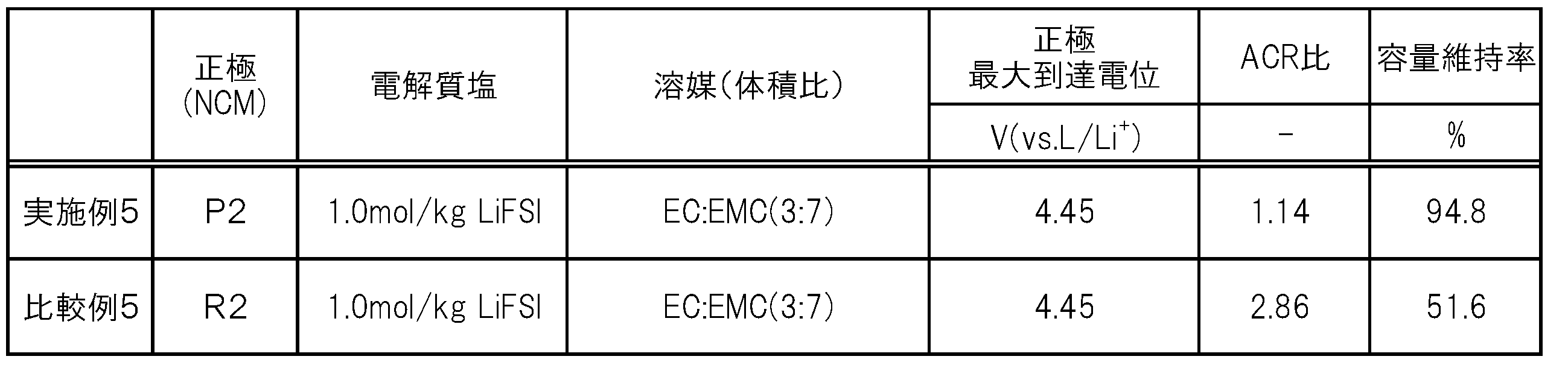
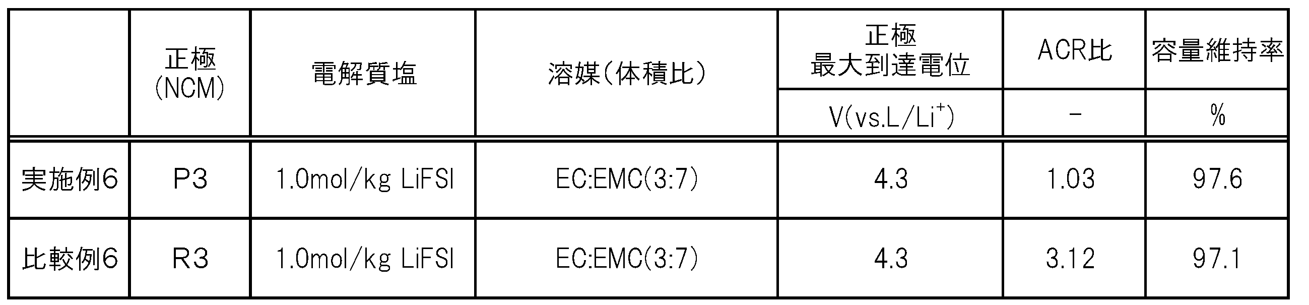
得られた実施例6及び比較例6の各非水電解質蓄電素子について、充電終止電圧を4.2V(正極の最大到達電位:4.3V(vs.Li/Li+))、放電終止電圧を2.75Vとしたこと以外は、上記「評価1」と同様にして初期充放電及び充放電サイクル試験を行った。初期充放電後、上記「評価1」と同様にして、正極合材表面のX線光電子分光測定を行った。ホスホン酸を用いた実施例6の正極合材(P3)においては、P2pに帰属されるピークは133から134eVの間に存在した。ホスホン酸を用いていない比較例6の正極合材(R3)においては、135eV以下の範囲にはP2pに帰属されるピークが確認できなかった。また、上記「評価1」と同様にして、内部抵抗及び容量維持率を測定した。測定結果を表3に示す。
(内部抵抗)
上記表1の実施例1と比較例1との対比からわかるように、非水電解質が電解質塩としてイミド塩を含有する非水電解質蓄電素子においては、正極合材のX線光電子分光スペクトルにおいてP2pに帰属されるピークが135eV以下の位置に存在する正極P1を用いることで、ACR比が小さく、充放電サイクル後の内部抵抗の上昇が抑制されることがわかる。同様の傾向は、表1の実施例4と比較例4との対比、表2の実施例5と比較例5との対比、及び表3の実施例6と比較例6との対比からも確認できる。なお、実施例1等は、充放電サイクル前と比べて充放電サイクル後に内部抵抗が小さくなっているものではなく、充放電サイクルに伴う内部抵抗の上昇が抑制されたものである。なかでも、実施例1、4のように、正極の最大到達電位が4.6V(vs.Li/Li+)以上となる充放電サイクルを行った場合に、正極合材のX線光電子分光スペクトルにおいてP2pに帰属されるピークが135eV以下の位置に存在する正極P1を用いることで、ACR比が小さく、充放電サイクル後の内部抵抗の上昇が抑制されるという効果が顕著に発揮されることがわかる(表1参照)。これは、電解質塩としてイミド塩を用いた場合の正極の作動電位が4.0V(vs.Li/Li+)以上となる充放電の際に生じやすいアルミニウムの酸化腐食は、正極の最大到達電位が貴であるほど顕著に生じるが、上記正極合材に形成されたリンのオキソ酸に由来する被膜による効果は、正極の最大到達電位にかかわらず発揮されたためと考えられる。
充放電サイクル後の容量維持率に着目すると、上記表1の実施例1と参考例1との対比からわかるように、正極合材のX線光電子分光スペクトルにおいてP2pに帰属されるピークが135eV以下の位置に存在する正極P1を用いた場合は、電解質塩としてイミド塩を用いることで充放電サイクル後の容量維持率が向上している。一方、比較例1と参考例2との対比で示されるように、従来の正極R1を用いた場合は、従来の知見どおり、電解質塩をLiPF6(参考例1)からイミド塩(実施例1)に換えると、充放電サイクル後の容量維持率が低下している。すなわち、正極合材のX線光電子分光スペクトルにおいてP2pに帰属されるピークが135eV以下の位置に存在する正極P1が用いられている場合、電解質塩として、アルミニウムの酸化腐食を生じさせやすいとされていたイミド塩を用いることで、充放電サイクル後の容量維持率が向上するという効果は、従来の知見からは予測できない特異な効果であるといえる。
2 電極体
3 容器
4 正極端子
4’ 正極リード
5 負極端子
5’ 負極リード
20 蓄電ユニット
30 蓄電装置
Claims (20)
- リン原子を含む正極合材を有する正極と、
イミド塩を含む非水電解質と
を備え、
上記正極合材のX線光電子分光スペクトルにおいて、P2pに帰属されるピークが135eV以下の位置に存在する非水電解質蓄電素子。 - 上記正極合材のX線光電子分光スペクトルにおいて、P2pに帰属されるピークが134eV以下の位置に存在する請求項1の非水電解質蓄電素子。
- 上記非水電解質における上記イミド塩の含有量が、0.5mol/kg以上2mol/kg以下である請求項1又は2の非水電解質蓄電素子。
- 上記非水電解質における上記イミド塩の含有量が、0.8mol/kg以上である請求項3の非水電解質蓄電素子。
- 上記非水電解質における上記イミド塩の含有量が、1.4mol/kg以下である請求項3又は4の非水電解質蓄電素子。
- 上記非水電解質における上記イミド塩の含有量が、1.2mol/kg以下である請求項3又は4の非水電解質蓄電素子。
- 上記非水電解質における上記イミド塩の含有量が、1.1mol/kg以下である請求項3又は4の非水電解質蓄電素子。
- 上記イミド塩は、リチウムイミド塩を含む請求項1~7のいずれかの非水電解質蓄電素子。
- 上記リチウムイミド塩は、フルオロスルホニル基、ジフルオロホスホニル基、及びフルオロアルキル基のうちのいずれかを含む請求項8の非水電解質蓄電素子。
- 上記リチウムイミド塩は、リチウムスルホニルイミド塩を含む請求項8又は9の非水電解質蓄電素子。
- 上記リチウムイミド塩は、リチウムビス(フルオロスルホニル)イミドを含む請求項1~7のいずれかの非水電解質蓄電素子。
- 上記非水電解質は、PF6アニオンを有する電解質塩を実質的に含有しない請求項1~11のいずれかの非水電解質蓄電素子。
- 上記非水電解質は、フッ素化カーボネートを含む請求項1~12のいずれかの非水電解質蓄電素子。
- 正極の最大到達電位が、4.4V(vs.Li/Li+)以上である請求項1~13のいずれかの非水電解質蓄電素子。
- 正極の最大到達電位が、4.5V(vs.Li/Li+)以上である請求項1~13のいずれかの非水電解質蓄電素子。
- 正極の最大到達電位が、4.6V(vs.Li/Li+)以上である請求項1~13のいずれかの非水電解質蓄電素子。
- 上記正極は、正極基材、及び正極合材層を有し、上記正極基材は、アルミニウム又はアルミニウム合金を含む請求項1~16のいずれかの非水電解質蓄電素子。
- 正極合材は、正極活物質及びリン原子を含み、上記正極活物質は、非水電解質蓄電素子の通常使用時の充電終止電圧における正極電位が4.0V(vs.Li/Li+)より貴となり得る正極活物質を含む請求項1~17のいずれかの非水電解質蓄電素子。
- リンのオキソ酸を含む正極合材ペーストを用いて作製される正極合材を有する正極と、
イミド塩を含む非水電解質と
を用いる非水電解質蓄電素子の製造方法。 - 上記リンのオキソ酸は、リン酸又はホスホン酸を含む請求項19の非水電解質蓄電素子の製造方法。
Priority Applications (4)
| Application Number | Priority Date | Filing Date | Title |
|---|---|---|---|
| US16/756,888 US20210098777A1 (en) | 2017-10-20 | 2018-09-14 | Nonaqueous electrolyte energy storage device and method for manufacturing nonaqueous electrolyte energy storage device |
| EP18868925.1A EP3686984B1 (en) | 2017-10-20 | 2018-09-14 | Nonaqueous electrolyte storage element and method for producing nonaqueous electrolyte storage element |
| CN201880067518.3A CN111316494B (zh) | 2017-10-20 | 2018-09-14 | 非水电解质蓄电元件和非水电解质蓄电元件的制造方法 |
| JP2019549155A JP7151714B2 (ja) | 2017-10-20 | 2018-09-14 | 非水電解質蓄電素子及び非水電解質蓄電素子の製造方法 |
Applications Claiming Priority (2)
| Application Number | Priority Date | Filing Date | Title |
|---|---|---|---|
| JP2017203397 | 2017-10-20 | ||
| JP2017-203397 | 2017-10-20 |
Publications (1)
| Publication Number | Publication Date |
|---|---|
| WO2019077919A1 true WO2019077919A1 (ja) | 2019-04-25 |
Family
ID=66174030
Family Applications (1)
| Application Number | Title | Priority Date | Filing Date |
|---|---|---|---|
| PCT/JP2018/034206 Ceased WO2019077919A1 (ja) | 2017-10-20 | 2018-09-14 | 非水電解質蓄電素子及び非水電解質蓄電素子の製造方法 |
Country Status (5)
| Country | Link |
|---|---|
| US (1) | US20210098777A1 (ja) |
| EP (1) | EP3686984B1 (ja) |
| JP (1) | JP7151714B2 (ja) |
| CN (1) | CN111316494B (ja) |
| WO (1) | WO2019077919A1 (ja) |
Cited By (4)
| Publication number | Priority date | Publication date | Assignee | Title |
|---|---|---|---|---|
| JP2021106113A (ja) * | 2019-12-26 | 2021-07-26 | エルジー・ケム・リミテッド | 正極、リチウムイオン二次電池、正極の製造方法、及びリチウムイオン二次電池の製造方法 |
| WO2022054781A1 (ja) * | 2020-09-08 | 2022-03-17 | 株式会社Gsユアサ | リチウム二次電池の製造方法及びリチウム二次電池 |
| JPWO2022215160A1 (ja) * | 2021-04-06 | 2022-10-13 | ||
| WO2026054018A1 (ja) * | 2024-09-04 | 2026-03-12 | 株式会社村田製作所 | 二次電池 |
Families Citing this family (3)
| Publication number | Priority date | Publication date | Assignee | Title |
|---|---|---|---|---|
| CN113782825B (zh) * | 2021-09-13 | 2023-07-21 | 蜂巢能源科技有限公司 | 一种固态电解质材料及其制备方法和应用 |
| WO2025093839A1 (fr) * | 2023-11-03 | 2025-05-08 | Arkema France | Procede de preparation d'un polymere fluore |
| FR3154999B1 (fr) * | 2023-11-03 | 2025-10-10 | Arkema France | Procédé de préparation d’un polymère fluoré |
Citations (8)
| Publication number | Priority date | Publication date | Assignee | Title |
|---|---|---|---|---|
| JP2007220335A (ja) * | 2006-02-14 | 2007-08-30 | Univ Nagoya | リチウムイオン二次電池 |
| WO2007139130A1 (ja) * | 2006-05-31 | 2007-12-06 | Sanyo Electric Co., Ltd. | 高電圧充電型非水電解質二次電池 |
| JP2009087885A (ja) * | 2007-10-03 | 2009-04-23 | Sony Corp | 正極の製造方法 |
| JP2013152825A (ja) * | 2012-01-24 | 2013-08-08 | Sony Corp | 電池ならびに電池パック、電子機器、電動車両、蓄電装置および電力システム |
| JP2014022291A (ja) * | 2012-07-20 | 2014-02-03 | Nippon Shokubai Co Ltd | 非水電解液及びこれを用いたリチウム二次電池 |
| JP2015079636A (ja) | 2013-10-16 | 2015-04-23 | 学校法人 関西大学 | リチウムイオン二次電池 |
| JP2017091993A (ja) * | 2015-11-17 | 2017-05-25 | 株式会社日本触媒 | リチウムイオン二次電池 |
| WO2017099201A1 (ja) * | 2015-12-11 | 2017-06-15 | 株式会社Gsユアサ | 非水電解質蓄電素子及びその製造方法 |
Family Cites Families (6)
| Publication number | Priority date | Publication date | Assignee | Title |
|---|---|---|---|---|
| JP4847675B2 (ja) * | 2002-10-23 | 2011-12-28 | パナソニック株式会社 | 非水電解質二次電池およびそれに用いる電解質 |
| JP4693373B2 (ja) * | 2004-07-21 | 2011-06-01 | 三洋電機株式会社 | 非水電解質電池 |
| JP2011070773A (ja) * | 2009-03-19 | 2011-04-07 | Equos Research Co Ltd | リチウムイオン電池用電極 |
| JP5678539B2 (ja) * | 2009-09-29 | 2015-03-04 | 三菱化学株式会社 | 非水系電解液電池 |
| JP2015201308A (ja) * | 2014-04-07 | 2015-11-12 | 旭化成株式会社 | 非水蓄電デバイス用電解液及びリチウムイオン二次電池 |
| WO2016132903A1 (ja) * | 2015-02-19 | 2016-08-25 | 株式会社リコー | 非水電解液蓄電素子 |
-
2018
- 2018-09-14 JP JP2019549155A patent/JP7151714B2/ja active Active
- 2018-09-14 WO PCT/JP2018/034206 patent/WO2019077919A1/ja not_active Ceased
- 2018-09-14 EP EP18868925.1A patent/EP3686984B1/en active Active
- 2018-09-14 US US16/756,888 patent/US20210098777A1/en not_active Abandoned
- 2018-09-14 CN CN201880067518.3A patent/CN111316494B/zh active Active
Patent Citations (8)
| Publication number | Priority date | Publication date | Assignee | Title |
|---|---|---|---|---|
| JP2007220335A (ja) * | 2006-02-14 | 2007-08-30 | Univ Nagoya | リチウムイオン二次電池 |
| WO2007139130A1 (ja) * | 2006-05-31 | 2007-12-06 | Sanyo Electric Co., Ltd. | 高電圧充電型非水電解質二次電池 |
| JP2009087885A (ja) * | 2007-10-03 | 2009-04-23 | Sony Corp | 正極の製造方法 |
| JP2013152825A (ja) * | 2012-01-24 | 2013-08-08 | Sony Corp | 電池ならびに電池パック、電子機器、電動車両、蓄電装置および電力システム |
| JP2014022291A (ja) * | 2012-07-20 | 2014-02-03 | Nippon Shokubai Co Ltd | 非水電解液及びこれを用いたリチウム二次電池 |
| JP2015079636A (ja) | 2013-10-16 | 2015-04-23 | 学校法人 関西大学 | リチウムイオン二次電池 |
| JP2017091993A (ja) * | 2015-11-17 | 2017-05-25 | 株式会社日本触媒 | リチウムイオン二次電池 |
| WO2017099201A1 (ja) * | 2015-12-11 | 2017-06-15 | 株式会社Gsユアサ | 非水電解質蓄電素子及びその製造方法 |
Non-Patent Citations (2)
| Title |
|---|
| JIANHUI WANG: "Superconcentrated electrolytes for a high-voltage lithium-ion battery", NATURE COMMUNICATIONS, vol. 7, 2016, pages 12032, XP055505812, DOI: 10.1038/ncomms12032 |
| See also references of EP3686984A4 |
Cited By (8)
| Publication number | Priority date | Publication date | Assignee | Title |
|---|---|---|---|---|
| JP2021106113A (ja) * | 2019-12-26 | 2021-07-26 | エルジー・ケム・リミテッド | 正極、リチウムイオン二次電池、正極の製造方法、及びリチウムイオン二次電池の製造方法 |
| JP7376348B2 (ja) | 2019-12-26 | 2023-11-08 | エルジー エナジー ソリューション リミテッド | 正極、リチウムイオン二次電池、正極の製造方法、及びリチウムイオン二次電池の製造方法 |
| WO2022054781A1 (ja) * | 2020-09-08 | 2022-03-17 | 株式会社Gsユアサ | リチウム二次電池の製造方法及びリチウム二次電池 |
| JPWO2022054781A1 (ja) * | 2020-09-08 | 2022-03-17 | ||
| JPWO2022215160A1 (ja) * | 2021-04-06 | 2022-10-13 | ||
| WO2022215160A1 (ja) * | 2021-04-06 | 2022-10-13 | TeraWatt Technology株式会社 | リチウム2次電池 |
| JP7646241B2 (ja) | 2021-04-06 | 2025-03-17 | TeraWatt Technology株式会社 | リチウム2次電池 |
| WO2026054018A1 (ja) * | 2024-09-04 | 2026-03-12 | 株式会社村田製作所 | 二次電池 |
Also Published As
| Publication number | Publication date |
|---|---|
| EP3686984A1 (en) | 2020-07-29 |
| JP7151714B2 (ja) | 2022-10-12 |
| EP3686984B1 (en) | 2024-06-12 |
| US20210098777A1 (en) | 2021-04-01 |
| CN111316494A (zh) | 2020-06-19 |
| JPWO2019077919A1 (ja) | 2020-09-17 |
| CN111316494B (zh) | 2025-04-25 |
| EP3686984A4 (en) | 2021-06-16 |
Similar Documents
| Publication | Publication Date | Title |
|---|---|---|
| CN111316494B (zh) | 非水电解质蓄电元件和非水电解质蓄电元件的制造方法 | |
| JP7455498B2 (ja) | 非水電解質、非水電解質蓄電素子及び非水電解質蓄電素子の製造方法 | |
| JP2018181772A (ja) | 非水電解質蓄電素子及びその製造方法 | |
| WO2018105701A1 (ja) | 非水電解質蓄電素子及びその製造方法 | |
| JP2019133773A (ja) | 非水電解質及び非水電解質蓄電素子 | |
| JP2018055886A (ja) | 炭素被覆正極活物質及びその製造方法、正極、並びに非水電解質蓄電素子 | |
| CN106257717A (zh) | 非水电解质二次电池 | |
| JP2018101612A (ja) | 非水電解質、及び非水電解質蓄電素子 | |
| WO2020067370A1 (ja) | 非水電解質、非水電解質蓄電素子、非水電解質蓄電素子の製造方法、及び非水電解質蓄電素子の使用方法 | |
| JP7828172B2 (ja) | 蓄電素子用非水電解質、非水電解質蓄電素子及び非水電解質蓄電素子の製造方法 | |
| JP7552013B2 (ja) | 非水電解液、非水電解液蓄電素子及び非水電解液蓄電素子の製造方法 | |
| JP7137757B2 (ja) | 非水電解質蓄電素子 | |
| JP7155719B2 (ja) | 非水電解質蓄電素子及び非水電解質蓄電素子の製造方法 | |
| JP7363792B2 (ja) | 非水電解質蓄電素子及び非水電解質蓄電素子の製造方法 | |
| JP2018049821A (ja) | 蓄電素子用非水電解質、非水電解質蓄電素子、及び非水電解質蓄電素子の製造方法 | |
| WO2018174061A1 (ja) | 非水電解質蓄電素子 | |
| CN114899352B (zh) | 非水电解质蓄电元件及其制造方法 | |
| JP7528418B2 (ja) | 非水電解質蓄電素子及び非水電解質蓄電素子の製造方法 | |
| JP2019145343A (ja) | 非水電解質、非水電解質蓄電素子及び非水電解質蓄電素子の製造方法 | |
| JP2019087350A (ja) | 蓄電素子及び蓄電素子の製造方法 | |
| JP6922242B2 (ja) | 非水電解質蓄電素子及び非水電解質蓄電素子の製造方法 | |
| JP2018116906A (ja) | 非水電解質、蓄電素子及び蓄電素子の製造方法 | |
| JP2018032477A (ja) | 非水電解質蓄電素子及びその製造方法 | |
| JP7831324B2 (ja) | 非水電解質蓄電素子、及び蓄電装置 | |
| WO2017145507A1 (ja) | 二次電池用非水電解質、非水電解質二次電池、及び非水電解質二次電池の製造方法 |
Legal Events
| Date | Code | Title | Description |
|---|---|---|---|
| 121 | Ep: the epo has been informed by wipo that ep was designated in this application |
Ref document number: 18868925 Country of ref document: EP Kind code of ref document: A1 |
|
| ENP | Entry into the national phase |
Ref document number: 2019549155 Country of ref document: JP Kind code of ref document: A |
|
| NENP | Non-entry into the national phase |
Ref country code: DE |
|
| ENP | Entry into the national phase |
Ref document number: 2018868925 Country of ref document: EP Effective date: 20200423 |
|
| WWG | Wipo information: grant in national office |
Ref document number: 201880067518.3 Country of ref document: CN |