WO2019078088A1 - Transmission - Google Patents
Transmission Download PDFInfo
- Publication number
- WO2019078088A1 WO2019078088A1 PCT/JP2018/037958 JP2018037958W WO2019078088A1 WO 2019078088 A1 WO2019078088 A1 WO 2019078088A1 JP 2018037958 W JP2018037958 W JP 2018037958W WO 2019078088 A1 WO2019078088 A1 WO 2019078088A1
- Authority
- WO
- WIPO (PCT)
- Prior art keywords
- rotation
- transmission
- central axis
- planetary
- shaft
- Prior art date
- Legal status (The legal status is an assumption and is not a legal conclusion. Google has not performed a legal analysis and makes no representation as to the accuracy of the status listed.)
- Ceased
Links
Images



Classifications
-
- F—MECHANICAL ENGINEERING; LIGHTING; HEATING; WEAPONS; BLASTING
- F16—ENGINEERING ELEMENTS AND UNITS; GENERAL MEASURES FOR PRODUCING AND MAINTAINING EFFECTIVE FUNCTIONING OF MACHINES OR INSTALLATIONS; THERMAL INSULATION IN GENERAL
- F16H—GEARING
- F16H13/00—Gearing for conveying rotary motion with constant gear ratio by friction between rotary members
- F16H13/06—Gearing for conveying rotary motion with constant gear ratio by friction between rotary members with members having orbital motion
- F16H13/08—Gearing for conveying rotary motion with constant gear ratio by friction between rotary members with members having orbital motion with balls or with rollers acting in a similar manner
-
- F—MECHANICAL ENGINEERING; LIGHTING; HEATING; WEAPONS; BLASTING
- F16—ENGINEERING ELEMENTS AND UNITS; GENERAL MEASURES FOR PRODUCING AND MAINTAINING EFFECTIVE FUNCTIONING OF MACHINES OR INSTALLATIONS; THERMAL INSULATION IN GENERAL
- F16H—GEARING
- F16H13/00—Gearing for conveying rotary motion with constant gear ratio by friction between rotary members
- F16H13/10—Means for influencing the pressure between the members
- F16H13/14—Means for influencing the pressure between the members for automatically varying the pressure mechanically
-
- F—MECHANICAL ENGINEERING; LIGHTING; HEATING; WEAPONS; BLASTING
- F16—ENGINEERING ELEMENTS AND UNITS; GENERAL MEASURES FOR PRODUCING AND MAINTAINING EFFECTIVE FUNCTIONING OF MACHINES OR INSTALLATIONS; THERMAL INSULATION IN GENERAL
- F16H—GEARING
- F16H37/00—Combinations of mechanical gearings, not provided for in groups F16H1/00 - F16H35/00
- F16H37/02—Combinations of mechanical gearings, not provided for in groups F16H1/00 - F16H35/00 comprising essentially only toothed or friction gearings
Definitions
- the present invention relates to a transmission.
- Japanese Patent Laid-Open No. 2001-304350 discloses a reduction gear using a traction drive.
- the reduction gear of this publication is a combination of a planetary gear and a traction drive. Then, the traction drive is disposed on the input side. The rotational power decelerated by the traction drive is further decelerated by the planetary gear device and output.
- an object of the present invention is to provide a transmission capable of improving back drivability.
- a transmission comprising an input shaft and an output shaft extending along a central axis and rotating about the central axis, wherein the output shaft is rotated at a speed different from that of the input shaft, A first rotation mechanism and a second rotation mechanism that shift the rotation of the input shaft and transmit it to the output shaft, and the first rotation mechanism is a sun roller that rotates integrally with the input shaft; A plurality of planet rollers disposed around the sun roller and supporting the rotation axes of the plurality of planet rollers that rotate around the rotation axis and the plurality of planet rollers that rotate along the rotation of the sun roller A planetary roller support portion that rotates around a central axis as the planetary roller revolves, and a rotation transmission shaft that rotates around the central axis together with the planetary roller support portion, wherein the second rotation mechanism A sun gear that rotates integrally with a rotation transmission shaft, a plurality of planet gears that are disposed around the sun gear so as to be rotatable around a rotation
- rolling resistance is reduced and back drivability is improved by pressing the planetary roller against the sun roller with a necessary minimum load by the pressure adjustment mechanism. Therefore, it is possible to finely adjust the input side (motor) according to the load of the output shaft.
- FIG. 1 is a cross-sectional view of a transmission.
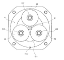
- FIG. 2 is a cross-sectional view taken along line II-II of FIG.
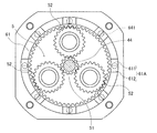
- FIG. 3 is a cross-sectional view taken along line III-III of FIG.
- FIG. 4 is a side view of the cam viewed from the radial direction.
- FIG. 5 is a diagram for explaining the operation of the pressure control mechanism.
- FIG. 6 is a diagram for explaining the operation of the pressure control mechanism.
- FIG. 7 is a diagram for explaining the operation of the pressure control mechanism.
- FIG. 8 is a partial cross-sectional view of a transmission of a modification.
- a direction parallel to the central axis of the transmission is "axial direction”
- a direction perpendicular to the central axis of the transmission is “radial direction”
- a direction along an arc centered on the central axis of the transmission is “axial direction”. It is referred to as “circumferential direction”.
- the “parallel direction” also includes a substantially parallel direction.
- the “orthogonal direction” also includes a substantially orthogonal direction.
- FIG. 1 is a cross-sectional view of the transmission 1.
- FIG. 2 is a cross-sectional view taken along line II-II of FIG.
- FIG. 3 is a cross-sectional view taken along line III-III of FIG.
- the transmission 1 of the present embodiment is used, for example, in a robot.
- the transmission 1 shifts the rotational movement of the drive motor of the robot and transmits it to the arm.
- the arm turns at a rotational speed changed by the transmission 1.
- the transmission 1 includes an input shaft 2 and an output shaft 3.
- the input shaft 2 and the output shaft 3 extend along the central axis 91 and rotate around the central axis 91.
- the transmission 1 rotates the output shaft 3 at a speed different from that of the input shaft 2.
- the transmission 1 includes a first rotation mechanism 4, a second rotation mechanism 5, a pressure adjustment mechanism 6, and a casing 7.
- the first rotation mechanism 4 and the second rotation mechanism 5 shift the rotation of the input shaft 2 and transmit the rotation to the output shaft 3.
- the casing 7 surrounds the central axis 91 and accommodates the first rotation mechanism 4 and the second rotation mechanism 5 therein.
- the casing 7 is non-rotatably fixed.
- the casing 7 has a shaft holding portion 71, a lid portion 72, and a side portion 73.
- the shaft holding portion 71 is a cylindrical member surrounding the central shaft 91.
- the lid portion 72 is a member which spreads radially outward from the shaft holding portion 71.
- the side portion 73 is a member extending along the axial direction from the radially outer end of the lid 72.
- the first rotation mechanism 4 described later has a sun roller 41 that rotates integrally with the input shaft 2.
- the shaft holding portion 71 holds the sun roller 41 via the bearing 81.
- the bearing 81 is, for example, a ball bearing. The bearing 81 enables the input shaft 2 and the sun roller 41 to rotate around the central axis 91 with respect to the casing 7.
- the second rotation mechanism 5 also has a planetary gear support 53 that rotates integrally with the output shaft 3.
- the side 73 holds the planetary gear support 53 via a bearing 82.
- the bearing 82 is, for example, a ball bearing. The bearing 82 enables the output shaft 3 and the planetary gear support 53 to rotate relative to the casing 7 about the central axis 91.
- the first rotation mechanism 4 has a sun roller 41, three planet rollers 42, a first planet roller support portion 431 and a second planet roller support portion 432, and a rotation transmission shaft 44.
- the sun roller 41 extends along the central axis 91 and rotates integrally with the input shaft 2 around the central axis 91.
- the sun roller 41 is rotatably supported by the shaft holding portion 71 of the casing 7 as described above.
- Three planet rollers 42 are arranged around the sun roller 41.
- the three planet rollers 42 are supported rotatably around a rotation shaft 92 by a first planetary roller support 431 and a second planetary roller support 432 described later, and rotatably supported around a central axis 91 Be done.
- the outer circumferential surface of each of the three planet rollers 42 contacts the outer circumferential surface of the sun roller 41.
- each of the three planet rollers 42 revolves around the central axis 91 while rotating on the rotation axis 92 as the sun roller 41 rotates.
- Each of the three planet rollers 42 has a first cylindrical portion 421 and a second cylindrical portion 422.
- the first cylindrical portion 421 surrounds the rotation shaft 92 and protrudes toward the output shaft 3 in the axial direction.
- the first cylindrical portion 421 has a conical shape whose diameter decreases toward the output shaft 3 side.
- the second cylindrical portion 422 surrounds the rotation shaft 92 and protrudes toward the input shaft 2 in the axial direction.
- the second cylindrical portion 422 has a conical shape whose diameter decreases toward the input shaft 2 side.
- the first planetary roller support portion 431 is circular when viewed from the axial direction.
- the first planetary roller support portion 431 is disposed closer to the output shaft 3 than the sun roller 41 and the planetary roller 42 in the axial direction.
- the first planetary roller support portion 431 inserts and fixes the rotation shaft 92 of each of the three planetary rollers 42.
- the first planetary roller support 431 supports each of the three planetary rollers 42.
- the first planetary roller support portion 431 supports each of the three planetary rollers 42 rotatably around the rotation shaft 92.
- the first planetary roller support portion 431 rotates about the central axis 91 as the three planetary rollers 42 revolve.
- the second planetary roller support portion 432 has an annular shape as viewed from the axial direction.
- the second planetary roller support portion 432 is disposed closer to the input shaft 2 than the sun roller 41 and the planetary roller 42 in the axial direction. That is, the first planetary roller support portion 431 and the second planetary roller support portion 432 are disposed to face each other with the sun roller 41 and the planetary roller 42 interposed therebetween in the axial direction.
- the second planetary roller support portion 432 inserts and fixes the rotation shaft 92 of each of the three planetary rollers 42. Specifically, the second planetary roller support 432 supports each of the three planetary rollers 42. At this time, the second planetary roller support portion 432 supports each of the three planetary rollers 42 rotatably around the rotation shaft 92.
- the second planetary roller support portion 432 surrounds the shaft holding portion 71 of the casing 7.
- a bearing 83 is provided between the second planetary roller support portion 432 and the shaft holding portion 71.
- the bearing 83 is, for example, a ball bearing.
- the second planetary roller support portion 432 is rotatable relative to the shaft holding portion 71 by the bearing 83.
- the first planetary roller support portion 431 rotates about the central axis 91 as the three planetary rollers 42 revolve.
- the rotation transmission shaft 44 has a cylindrical shape extending along the central axis 91.
- the rotation transmission shaft 44 is provided on the first planetary roller support portion 431, and rotates with the first planetary roller support portion 431 around the central axis 91. That is, the rotation transmission shaft 44 rotates around the central axis 91 as the three planetary rollers 42 revolve.
- a support plate 531 of a planetary gear support 53 described later is supported at an end portion on the output shaft 3 side of the rotation transmission shaft 44 via a bearing 84.
- Each of the first planetary roller support 431, the second planetary roller support 432, the rotation transmission shaft 44 and the rotation shaft 92 of the first rotation mechanism 4 is integrally supported by the bearing 83 and the bearing 84.
- the second rotation mechanism 5 includes a sun gear 51, three planet gears 52, and a planet gear support 53.
- the sun gear 51 is provided on the rotation transmission shaft 44 of the first rotation mechanism 4.
- the sun gear 51 rotates integrally with the rotation transmission shaft 44 about the central axis 91.
- Each of the three planet gears 52 is disposed around the sun gear 51.
- Each of the three planetary gears 52 is rotatably supported about a rotational shaft 93 by a planetary gear support 53 described later, and supported so as to revolve around a central shaft 91.
- the three planet gears 52 mesh with the sun gear 51.
- each of the three planetary gears 52 revolves around the central axis 91 while rotating on the rotation axis 93 as the sun gear 51 rotates.
- the planetary gear support 53 has a support plate 531 and a rotating shaft 532.
- the support plate 531 is circular when viewed from the axial direction.
- the support plate 531 is disposed closer to the output shaft 3 than the sun gear 51 and the planetary gear 52 in the axial direction.
- the support plate 531 supports the rotation shaft 93 of each of the three planetary gears 52.
- the support plate 531 rotatably supports each of the three planetary gears 52 around the rotation shaft 93.
- the rotation transmission shaft 44 is supported by the support plate 531 via the bearing 84.
- the bearing 84 is, for example, a ball bearing.
- the support plate 531 rotates about the central axis 91 as the three planetary gears 52 revolve.
- the rotation axis 532 is a cylindrical shape extending along the central axis 91.
- the rotation shaft 532 is provided on the support plate 531 and rotates around the central axis 91 together with the support plate 531.
- the rotating shaft 532 is rotatably supported on the side 73 of the casing 7 via a bearing 82.
- the output shaft 3 is provided on the rotating shaft 532. Then, the output shaft 3 rotates relative to the casing 7 integrally with the rotation shaft 532 around the central shaft 91.
- the pressure adjustment mechanism 6 is a mechanism that generates a pressing force that presses the plurality of planetary rollers 42 radially inward.
- the pressure control mechanism 6 is disposed radially inward of the side portion 73 of the casing 7.
- the pressure control mechanism 6 has an internal gear 61, a first annular member 62, a second annular member 63, a cam 64, and a spring 65.
- the internal gear 61 is disposed radially outside of the three planetary gears 52 as shown in FIGS. 1 and 3.
- the internal gear 61 is rotatable about a central axis 91 and meshes with the three planet gears 52.
- the internal gear 61 rotates around the central axis 91 by meshing with the three planetary gears 52.
- the rotation angle of the internal gear 61 in the circumferential direction is small.
- the internal gear 61 rotates to such an extent that the rolling element 641 does not come off from the first recess 61A and the second recess 62A, which will be described later with reference to FIG.
- the first annular member 62 and the second annular member 63 are annular members surrounding the central axis 91 when viewed from the axial direction.
- the first annular member 62 and the second annular member 63 are provided on the inner peripheral surface of the side portion 73 by the key 73A so as not to rotate about the central axis 91.
- the first annular member 62 and the second annular member 63 are axially aligned with the internal gear 61, and are disposed closer to the input shaft 2 than the internal gear 61 is.
- the first annular member 62 is disposed radially outward of the first cylindrical portion 421 so as to be axially displaceable. Further, the first annular member 62 axially faces the internal gear 61. A cam 64 described later is provided between the internal gear 61 and the first annular member 62.
- the inner circumferential surface of the first annular member 62 abuts on the outer circumferential surface of the first cylindrical portion 421 of the planetary roller 42.
- the inner circumferential surface of the first annular member 62 is an example of the “first contact portion” in the present application.
- the second annular member 63 is disposed radially outward of the second cylindrical portion 422 so as to be axially displaceable. Further, the second annular member 63 is opposed to the first annular member 62 in the axial direction, and the planetary roller 42 is interposed between the first annular member 62 and the second annular member 63.
- the inner circumferential surface of the second annular member 63 abuts on the outer circumferential surface of the second cylindrical portion 422 of the planetary roller 42.
- the inner circumferential surface of the second annular member 63 is an example of the “second contact portion” in the present application.
- FIG. 4 is a side view of the cam 64 viewed from the radial direction.
- FIG. 4 is a view showing the internal gear 61 not rotating.
- the cam 64 has a first recess 61A provided in the internal gear 61, a second recess 62A provided in the first annular member 62, and a rolling element 641.
- the first recess 61 ⁇ / b> A is provided on the facing surface of the internal gear 61 facing the first annular member 62 in the axial direction.
- the first recess 61 ⁇ / b> A is a groove which is recessed in a V-shape toward the output shaft 3 in the axial direction from the facing surface of the internal gear 61.
- the first recess 61 ⁇ / b> A has an inclined surface 611 and an inclined surface 612.
- eight first concave portions 61A are provided at equal intervals along the circumferential direction centering on the central axis 91, as shown in FIG.
- the second recess 62 ⁇ / b> A is provided on the opposite surface of the first annular member 62 that faces the internal gear 61 in the axial direction.
- the second recess 62A is a groove which is recessed in a V-shape toward the input shaft 2 in the axial direction from the opposing surface of the first annular member 62.
- the second recess 62A has an inclined surface 621 and an inclined surface 622. Similar to the first recess 61A, eight second recesses 62A are provided at equal intervals along the circumferential direction centering on the central axis 91.
- the first recess 61A and the second recess 62A face each other in the axial direction to form a space therebetween.
- the rolling element 641 is a spherical rigid body interposed in the space between the first recess 61A and the second recess 62A.
- the rolling elements 641 are respectively inclined surfaces 611 and 612 of the first recess 61A and inclined surfaces 621 and 622 of the second recess 62A.
- Contact The rolling element 641 rolls on the inclined surfaces 611 and 612 of the first recess 61A and the inclined surfaces 621 and 622 of the second recess 62A as the internal gear 61 rotates.
- the spring 65 is located on the side of the output shaft 3 in the axial direction of the internal gear 61, and is provided so as to be sandwiched between the internal gear 61 and the side portion 73.
- the spring 65 is an elastic member that presses the plurality of planet rollers 42 radially inward.
- the spring 65 presses the internal gear 61 toward the first annular member 62.
- the pressing force of the spring 65 is made by the inclined surface 421 of the first cylindrical portion of the planet roller 42. A radially inward pressure is generated.
- the pressure adjustment mechanism 6 can improve the performance (back drivability) to make the small external force applied to the output shaft 3 easy to be transmitted to the input shaft 2. By improving the back drivability, the rotation control on the input shaft 2 side can be performed with high accuracy in accordance with the impact (load) applied to the output shaft 3. Moreover, in the first rotation mechanism 4, the speed reduction ratio can be accurately obtained by the pressure adjustment mechanism 6. Furthermore, slippage between the planetary roller 42, the first annular member 62, the second annular member 63, and the sun roller 41 can be reduced by the pressure adjustment mechanism 6, and the occurrence of lost motion can be prevented. The operation of the pressure control mechanism 6 will be described in detail later.
- a motor (not shown) is connected to the input shaft 2 to apply a rotational driving force.
- the sun roller 41 also rotates integrally with the input shaft 2.
- the sun roller 41 rotates, the three planet rollers 42 in contact with the sun roller 41 revolve around the central axis 91 while rotating on the rotational axis 92.
- the first planet roller support portion 431 and the rotation transmission shaft 44 rotate around the central axis 91.
- the sun gear 51 rotates around the central axis 91 integrally with the rotation transmission shaft 44.
- the number of rotations of the first planetary roller support portion 431 and the rotation transmission shaft 44 is lower than the number of rotations of the input shaft 2 and the sun roller 41. That is, the first rotation mechanism 4 reduces the rotational speed of the input shaft 2 and transmits it to the second rotation mechanism 5.
- the sun gear 51 rotates around the central axis 91
- the three planetary gears 52 meshing with the sun gear 51 revolve around the central axis 91 while rotating about the rotational axis 93.
- the planetary gear support 53 rotates around the central axis 91.
- the rotation speed of the planetary gear support 53 is lower than the rotation speed of the sun gear 51.
- the output shaft 3 that rotates integrally with the planetary gear support portion 53 rotates at a rotational speed lower than the rotational speed of the sun gear 51. That is, the second rotation mechanism 5 further decelerates the rotational speed of the input shaft 2 decelerated by the first rotation mechanism 4 and transmits it to the output shaft 3.
- the pressure control mechanism 6 acts to generate a pressing force inward in the radial direction on the planetary roller 42.
- the three planet gears 52 revolve around the central axis 91 when the input shaft 2 rotates.
- the three planetary gears 52 try to revolve around the central axis 91 when a load in the rotational direction acts on the output shaft 3. That is, the pressure adjustment mechanism 6 generates a pressing force for pressing the plurality of planet rollers 42 radially inward according to the rotation of the input shaft 2 or the load in the rotation direction of the output shaft 3.
- FIG. 5 is a side view of the cam 64 viewed from the radial direction.
- the internal gear 61, the first annular member 62, and the rolling elements 641 when a load in the rotational direction is not acting on the internal gear 61 are indicated by broken lines.
- FIG. 6 is a view showing the state of the spring 65 when no load in the rotational direction acts on the internal gear 61.
- FIG. 7 is a view showing the state of the spring 65 when a load in the rotational direction acts on the internal gear 61.
- the internal gear 61 When no load in the rotational direction acts on the internal gear 61, the internal gear 61 is pressed by the spring 65 toward the first annular member 62, as shown in FIG.
- the inner circumferential surface of the first annular member 62 abuts on the outer circumferential surface of the first cylindrical portion 421.
- the contact position between the inner peripheral surface of the first annular member 62 and the outer peripheral surface of the first cylindrical portion 421 is on the side of the input shaft 2 in the axial direction.
- Move to The first cylindrical portion 421 has a conical shape whose diameter decreases toward the output shaft 3 side. For this reason, when the contact position moves, the pressing force with which the first annular member 62 presses the first cylindrical portion 421 becomes strong. Similarly, the pressing force with which the second annular member 63 presses the second cylindrical portion 422 also becomes strong.
- the pressure adjusting mechanism 6 moves the plurality of planetary rollers 42 radially inward even when the three planetary rollers 42 do not rotate, that is, even when neither the input shaft 2 nor the output shaft 3 rotates. Generate pressing force to press.
- the first annular member 62 presses the first cylindrical portion 421 radially inward.
- the pressing force at this time is stronger than in the case of FIG.
- the pressing force with which the second annular member 63 presses the second cylindrical portion 422 also becomes strong. That is, when a load acts on the internal gear 61, the planetary roller 42 presses the sun roller 41 more strongly than when no load acts on the internal gear 61.
- FIG. 8 is a partial cross-sectional view of a transmission of a modification.
- the spring 65 is provided on the input shaft 2 side of the second annular member 63 in the axial direction.
- the cam 64 is provided on the output shaft 3 side of the internal gear 61 in the axial direction.
- a slide bearing is provided between the internal gear 61 and the first annular member 62. Even with this configuration, it is possible to generate a radially inward pressing force on the planetary roller 42 by using the pressing force of the cam 64 and the elastic force of the spring 65.
- the transmission 1 has been described as being used for a robot, but is not limited thereto. Further, the number of planet rollers 42 and planet gears 52 is not limited to the number described in the above embodiment.
- the present application is applicable to a transmission.
Landscapes
- Engineering & Computer Science (AREA)
- General Engineering & Computer Science (AREA)
- Mechanical Engineering (AREA)
- Friction Gearing (AREA)
Abstract
L'invention concerne une transmission dans laquelle un arbre de sortie est mis en rotation à une vitesse différente de celle d'un arbre primaire, qui est pourvue d'un premier mécanisme de rotation et d'un second mécanisme de rotation. Le premier mécanisme de rotation comporte un rouleau planétaire qui tourne d'un seul tenant avec l'arbre primaire, une pluralité de rouleaux satellites qui tournent à mesure que le rouleau planétaire tourne, une section de support de rouleaux satellites qui tourne autour d'un axe central lorsque la pluralité de rouleaux satellites tournent, et un arbre de transmission de rotation qui tourne autour de l'axe central avec la section de support de rouleaux satellites. Le second mécanisme de rotation comporte un engrenage planétaire qui tourne d'un seul tenant avec l'arbre de transmission de rotation, une pluralité d'engrenages satellites qui s'engrènent avec l'engrenage planétaire, et une section de support d'engrenages satellites qui tourne autour de l'axe central lorsque la pluralité d'engrenages satellites tournent. L'arbre de sortie tourne autour de l'axe central avec la section de support d'engrenages satellites. La transmission est en outre pourvue d'un mécanisme de régulation de pression qui presse radialement vers l'intérieur la pluralité de rouleaux satellites en fonction d'une charge dans la direction de rotation de l'arbre de sortie.
Priority Applications (2)
| Application Number | Priority Date | Filing Date | Title |
|---|---|---|---|
| CN201880066669.7A CN111212993B (zh) | 2017-10-18 | 2018-10-11 | 变速器 |
| JP2019549233A JP7207628B2 (ja) | 2017-10-18 | 2018-10-11 | 変速機 |
Applications Claiming Priority (2)
| Application Number | Priority Date | Filing Date | Title |
|---|---|---|---|
| JP2017-201499 | 2017-10-18 | ||
| JP2017201499 | 2017-10-18 |
Publications (1)
| Publication Number | Publication Date |
|---|---|
| WO2019078088A1 true WO2019078088A1 (fr) | 2019-04-25 |
Family
ID=66173951
Family Applications (1)
| Application Number | Title | Priority Date | Filing Date |
|---|---|---|---|
| PCT/JP2018/037958 Ceased WO2019078088A1 (fr) | 2017-10-18 | 2018-10-11 | Transmission |
Country Status (3)
| Country | Link |
|---|---|
| JP (1) | JP7207628B2 (fr) |
| CN (1) | CN111212993B (fr) |
| WO (1) | WO2019078088A1 (fr) |
Cited By (1)
| Publication number | Priority date | Publication date | Assignee | Title |
|---|---|---|---|---|
| JP2021134847A (ja) * | 2020-02-27 | 2021-09-13 | 日本電産シンポ株式会社 | ハイブリッド減速機およびモータ付きハイブリッド減速機 |
Families Citing this family (1)
| Publication number | Priority date | Publication date | Assignee | Title |
|---|---|---|---|---|
| JP2020159535A (ja) * | 2019-03-28 | 2020-10-01 | 日本電産シンポ株式会社 | トラクション減速機 |
Citations (3)
| Publication number | Priority date | Publication date | Assignee | Title |
|---|---|---|---|---|
| JP2011252603A (ja) * | 2006-03-24 | 2011-12-15 | Toyota Central R&D Labs Inc | 動力伝達装置 |
| JP2014055657A (ja) * | 2012-09-14 | 2014-03-27 | Toyota Central R&D Labs Inc | 遊星ローラ機構 |
| JP2017141910A (ja) * | 2016-02-10 | 2017-08-17 | 武蔵精密工業株式会社 | 伝動装置 |
Family Cites Families (8)
| Publication number | Priority date | Publication date | Assignee | Title |
|---|---|---|---|---|
| JPH05157148A (ja) * | 1991-11-06 | 1993-06-22 | Shimpo Ind Co Ltd | 摩擦伝動変速機 |
| TWI257758B (en) * | 2000-09-14 | 2006-07-01 | Sumitomo Heavy Industries | Series of motors with speed reducers |
| JP2002295606A (ja) * | 2001-03-28 | 2002-10-09 | Sumitomo Heavy Ind Ltd | 2段形減速機及びモータ付き2段形減速機 |
| US10309501B2 (en) * | 2014-05-23 | 2019-06-04 | Nsk Ltd. | Friction roller-type transmission |
| JP2016048112A (ja) * | 2014-08-25 | 2016-04-07 | 日本精工株式会社 | 摩擦ローラ式減速機 |
| JP2016070285A (ja) * | 2014-09-26 | 2016-05-09 | 日本電産シンポ株式会社 | 減速装置 |
| JP6650724B2 (ja) * | 2015-10-19 | 2020-02-19 | 日本電産シンポ株式会社 | 変速機 |
| JP6642079B2 (ja) * | 2016-02-12 | 2020-02-05 | 日本精工株式会社 | 摩擦ローラ式減速機 |
-
2018
- 2018-10-11 JP JP2019549233A patent/JP7207628B2/ja active Active
- 2018-10-11 CN CN201880066669.7A patent/CN111212993B/zh active Active
- 2018-10-11 WO PCT/JP2018/037958 patent/WO2019078088A1/fr not_active Ceased
Patent Citations (3)
| Publication number | Priority date | Publication date | Assignee | Title |
|---|---|---|---|---|
| JP2011252603A (ja) * | 2006-03-24 | 2011-12-15 | Toyota Central R&D Labs Inc | 動力伝達装置 |
| JP2014055657A (ja) * | 2012-09-14 | 2014-03-27 | Toyota Central R&D Labs Inc | 遊星ローラ機構 |
| JP2017141910A (ja) * | 2016-02-10 | 2017-08-17 | 武蔵精密工業株式会社 | 伝動装置 |
Cited By (2)
| Publication number | Priority date | Publication date | Assignee | Title |
|---|---|---|---|---|
| JP2021134847A (ja) * | 2020-02-27 | 2021-09-13 | 日本電産シンポ株式会社 | ハイブリッド減速機およびモータ付きハイブリッド減速機 |
| JP7448111B2 (ja) | 2020-02-27 | 2024-03-12 | ニデックドライブテクノロジー株式会社 | ハイブリッド減速機およびモータ付きハイブリッド減速機 |
Also Published As
| Publication number | Publication date |
|---|---|
| CN111212993B (zh) | 2023-06-13 |
| JP7207628B2 (ja) | 2023-01-18 |
| CN111212993A (zh) | 2020-05-29 |
| JPWO2019078088A1 (ja) | 2020-11-05 |
Similar Documents
| Publication | Publication Date | Title |
|---|---|---|
| CN102782364B (zh) | 动力传递装置 | |
| CN103797274B (zh) | 无级变速器 | |
| WO2012131921A1 (fr) | Transmission à variation continue | |
| US7575530B2 (en) | Planetary roller transmission device and vehicle comprising same | |
| JP5203209B2 (ja) | 無段変速装置 | |
| WO2019078088A1 (fr) | Transmission | |
| JP2005188701A (ja) | 摩擦伝動装置 | |
| JP7068102B2 (ja) | ハイポサイクロイド減速機 | |
| JP4948968B2 (ja) | 遊星ローラ式変速機 | |
| JP2020133719A (ja) | トラクション変速機およびアクチュエータ | |
| JP6265061B2 (ja) | 遊星ローラ式トラクションドライブ装置 | |
| JP2011190882A (ja) | 無段変速機 | |
| JP2009047218A (ja) | 無段変速装置 | |
| JPH0243934B2 (fr) | ||
| JP2025082530A (ja) | ダンパ装置 | |
| JP2001065653A (ja) | 摩擦ローラ式変速装置 | |
| JP3835847B2 (ja) | 遊星ローラ式変速装置 | |
| JP5488492B2 (ja) | 無段変速機 | |
| JP2009121574A (ja) | 摩擦式増減速装置 | |
| JP2026049366A (ja) | ロック機構、減速装置およびギヤドモータ | |
| JPH0735212A (ja) | 減速装置 | |
| WO2016021410A1 (fr) | Dispositif stabilisateur | |
| JP2004100927A (ja) | 変速装置 | |
| JP5761445B2 (ja) | 無段変速機 | |
| WO2019009176A1 (fr) | Réducteur de vitesse |
Legal Events
| Date | Code | Title | Description |
|---|---|---|---|
| 121 | Ep: the epo has been informed by wipo that ep was designated in this application |
Ref document number: 18867722 Country of ref document: EP Kind code of ref document: A1 |
|
| ENP | Entry into the national phase |
Ref document number: 2019549233 Country of ref document: JP Kind code of ref document: A |
|
| NENP | Non-entry into the national phase |
Ref country code: DE |
|
| 122 | Ep: pct application non-entry in european phase |
Ref document number: 18867722 Country of ref document: EP Kind code of ref document: A1 |