WO2019078099A1 - Commutateur - Google Patents
Commutateur Download PDFInfo
- Publication number
- WO2019078099A1 WO2019078099A1 PCT/JP2018/038033 JP2018038033W WO2019078099A1 WO 2019078099 A1 WO2019078099 A1 WO 2019078099A1 JP 2018038033 W JP2018038033 W JP 2018038033W WO 2019078099 A1 WO2019078099 A1 WO 2019078099A1
- Authority
- WO
- WIPO (PCT)
- Prior art keywords
- housing
- movable
- movable member
- switch
- sealing
- Prior art date
- Legal status (The legal status is an assumption and is not a legal conclusion. Google has not performed a legal analysis and makes no representation as to the accuracy of the status listed.)
- Ceased
Links
Images








Classifications
-
- H—ELECTRICITY
- H01—ELECTRIC ELEMENTS
- H01H—ELECTRIC SWITCHES; RELAYS; SELECTORS; EMERGENCY PROTECTIVE DEVICES
- H01H13/00—Switches having rectilinearly-movable operating part or parts adapted for pushing or pulling in one direction only, e.g. push-button switch
- H01H13/02—Details
- H01H13/12—Movable parts; Contacts mounted thereon
- H01H13/14—Operating parts, e.g. push-button
-
- H—ELECTRICITY
- H01—ELECTRIC ELEMENTS
- H01H—ELECTRIC SWITCHES; RELAYS; SELECTORS; EMERGENCY PROTECTIVE DEVICES
- H01H13/00—Switches having rectilinearly-movable operating part or parts adapted for pushing or pulling in one direction only, e.g. push-button switch
- H01H13/02—Details
- H01H13/04—Cases; Covers
- H01H13/06—Dustproof, splashproof, drip-proof, waterproof or flameproof casings
- H01H13/063—Casings hermetically closed by a diaphragm through which passes an actuating member
-
- H—ELECTRICITY
- H01—ELECTRIC ELEMENTS
- H01H—ELECTRIC SWITCHES; RELAYS; SELECTORS; EMERGENCY PROTECTIVE DEVICES
- H01H13/00—Switches having rectilinearly-movable operating part or parts adapted for pushing or pulling in one direction only, e.g. push-button switch
- H01H13/02—Details
- H01H13/10—Bases; Stationary contacts mounted thereon
-
- H—ELECTRICITY
- H01—ELECTRIC ELEMENTS
- H01H—ELECTRIC SWITCHES; RELAYS; SELECTORS; EMERGENCY PROTECTIVE DEVICES
- H01H13/00—Switches having rectilinearly-movable operating part or parts adapted for pushing or pulling in one direction only, e.g. push-button switch
- H01H13/50—Switches having rectilinearly-movable operating part or parts adapted for pushing or pulling in one direction only, e.g. push-button switch having a single operating member
- H01H13/52—Switches having rectilinearly-movable operating part or parts adapted for pushing or pulling in one direction only, e.g. push-button switch having a single operating member the contact returning to its original state immediately upon removal of operating force, e.g. bell-push switch
-
- H—ELECTRICITY
- H01—ELECTRIC ELEMENTS
- H01H—ELECTRIC SWITCHES; RELAYS; SELECTORS; EMERGENCY PROTECTIVE DEVICES
- H01H21/00—Switches operated by an operating part in the form of a pivotable member acted upon directly by a solid body, e.g. by a hand
- H01H21/02—Details
- H01H21/04—Cases; Covers
- H01H21/08—Dustproof, splashproof, drip-proof, waterproof, or flameproof casings
-
- H—ELECTRICITY
- H01—ELECTRIC ELEMENTS
- H01H—ELECTRIC SWITCHES; RELAYS; SELECTORS; EMERGENCY PROTECTIVE DEVICES
- H01H21/00—Switches operated by an operating part in the form of a pivotable member acted upon directly by a solid body, e.g. by a hand
- H01H21/02—Details
- H01H21/18—Movable parts; Contacts mounted thereon
- H01H21/22—Operating parts, e.g. handle
-
- H—ELECTRICITY
- H01—ELECTRIC ELEMENTS
- H01H—ELECTRIC SWITCHES; RELAYS; SELECTORS; EMERGENCY PROTECTIVE DEVICES
- H01H21/00—Switches operated by an operating part in the form of a pivotable member acted upon directly by a solid body, e.g. by a hand
- H01H21/02—Details
- H01H21/18—Movable parts; Contacts mounted thereon
- H01H21/36—Driving mechanisms
-
- H—ELECTRICITY
- H01—ELECTRIC ELEMENTS
- H01H—ELECTRIC SWITCHES; RELAYS; SELECTORS; EMERGENCY PROTECTIVE DEVICES
- H01H3/00—Mechanisms for operating contacts
- H01H3/02—Operating parts, i.e. for operating driving mechanism by a mechanical force external to the switch
- H01H3/12—Push-buttons
-
- H—ELECTRICITY
- H01—ELECTRIC ELEMENTS
- H01H—ELECTRIC SWITCHES; RELAYS; SELECTORS; EMERGENCY PROTECTIVE DEVICES
- H01H2221/00—Actuators
- H01H2221/024—Transmission element
- H01H2221/026—Guiding or lubricating nylon
-
- H—ELECTRICITY
- H01—ELECTRIC ELEMENTS
- H01H—ELECTRIC SWITCHES; RELAYS; SELECTORS; EMERGENCY PROTECTIVE DEVICES
- H01H2221/00—Actuators
- H01H2221/058—Actuators to avoid tilting or skewing of contact area or actuator
-
- H—ELECTRICITY
- H01—ELECTRIC ELEMENTS
- H01H—ELECTRIC SWITCHES; RELAYS; SELECTORS; EMERGENCY PROTECTIVE DEVICES
- H01H2221/00—Actuators
- H01H2221/088—Actuators actuable from different directions
Definitions
- the present disclosure relates to a switch.
- Patent Document 1 discloses a switch device including a housing having a storage portion, and an operation lever and a coil spring stored in the storage portion.
- the operation lever is attached to the housing in a state where a part thereof protrudes from the storage portion, and is biased in the direction of protruding from the storage portion by the coil spring.
- the operation lever has a substantially triangular flat plate shape in which one vertex is exposed from the storage portion and two vertices are stored in the storage portion, and among the three vertexes of the substantially triangular flat plate shape It is attached to the housing so as to be pivotable in two mutually opposing directions, with any one of two apexes located in the storage section as a pivot point.
- the size of the gap between the control lever and the housing varies largely depending on the position of the control lever, so that the seal between the control lever and the housing can be sealed by a sealing member or the like. It was difficult and there were cases where high sealing performance could not be secured.
- the present disclosure aims to provide a switch that has high sealing performance and can be operated from multiple directions.
- An example switch of the present disclosure is: A housing having an operation surface provided with an operation hole, and a housing portion provided inside and connected to the outside through the operation hole; It is accommodated in the accommodation portion, extends along the movable direction orthogonal to the operation surface from the accommodation portion to the outside of the housing via the operation hole, and is provided at an end portion on the outside of the housing A movable member having an operating portion, and reciprocably disposed with respect to the housing along the movable direction; A guide portion for guiding the movable member in the movable direction; A sealing member for sealing a gap between the movable member and the housing inside the housing portion; The operating portion linearly extends from the operating surface toward the distal end side of the housing of the movable member, and the central axis extends along the movable direction of the movable member as it is separated from the operating surface. It has a plurality of inclined surfaces which are respectively inclined to approach.
- the movable member disposed to be reciprocally movable with respect to the housing along the movable direction, the guide portion guiding the movable member in the movable direction, and the movable member and the housing in the housing portion And a seal member for sealing the gap between the two.
- the movable member linearly extends from the operation surface toward the distal end side of the housing of the movable member, and has a plurality of inclinations which are inclined to approach the central axis of the movable member as they are separated from the operation surface.
- An operation unit having a surface is provided. As a result, it is possible to realize a switch that has high sealing performance and can be operated from multiple directions.
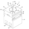
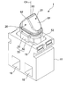
- FIG. 1 is a perspective view showing a switch of a first embodiment of the present disclosure.
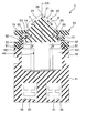
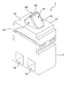
- FIG. 2 is a plan view of the switch of FIG. 1; Sectional drawing along the III-III line of FIG. The perspective view of the switch of FIG. 1 which removed the cover and the sealing member.
- FIG. 7 is a perspective view showing a first modified example of the switch of FIG. 1;
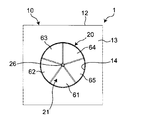
- FIG. 6 is a plan view of the switch of FIG. 5;
- FIG. 7 is a perspective view showing a second modification of the switch of FIG. 1;
- FIG. 8 is a plan view of the switch of FIG. 7; Sectional drawing in alignment with the IX-IX line of FIG.
- 11 is a plan view of the switch of FIG.
- FIG. 12 is a cross-sectional view along the line XII-XII in FIG.
- FIG. 11 is a perspective view of the switch of FIG. 10 with the cover and seal members removed
- the switch 1 according to the first embodiment of the present disclosure includes a housing 10 and a movable member 20 accommodated in the housing 10, as shown in FIGS. 1 and 2.
- the housing 10 has an operation surface 13 provided with the operation hole 14 and a housing portion 15 (shown in FIG. 3) provided therein.
- the movable member 20 is housed in the housing portion 15 of the housing 10 in a state where a part of the movable member 20 is exposed to the outside of the housing 10 through the operation hole 14. Further, the movable member 20 is arranged to be reciprocally movable with respect to the housing 10 along a movable direction which intersects (eg, is orthogonal to) the operation surface 13 via the operation hole 14. The reciprocation of the movable member 20 switches the operation / non-operation of the contact mechanism portion 40 (shown in FIG. 3) provided inside the housing 10 to turn the switch 1 on and off.
- the switch 1 is provided with a guide portion 30 for guiding the movable member 20 in the movable direction.
- the guide portion 30 is disposed inside the housing portion 15.
- the cover 12 of the housing 10, the contact mechanism portion 40, and the seal member 50 described later are omitted.
- the housing 10 is, as shown in FIG. 1, constituted of a box-shaped case 11 and a cover 12 of a substantially rectangular parallelepiped, and as shown in FIG. 3, an accommodating portion 15 surrounded by the case 11 and the cover 12 is provided therein. It is done.
- the case 11 is provided with two through holes 16 passing through a pair of opposite side surfaces below the housing portion 15.
- portions of a pair of terminal portions 41 described later are disposed in the interiors of the respective through holes 16 respectively, and conductor portions (shown in the drawings) of the wires inserted into the respective through holes 16. And so on can be connected to the pair of terminal portions 41.
- the upper surface of the cover 12 constitutes an operation surface 13, and a circular operation hole 14 is disposed substantially at the center of the operation surface 13.
- the housing portion 15 inside the housing 10 and the outside of the housing 10 are connected via the operation hole 14.
- a sealing notch 121 (an example of a second sealing connection) is provided at an end of the cover 12 on the side facing the case 11.
- the sealing notch portion 121 is provided over the entire periphery of the inner surface of the housing portion 15 of the cover 12 around the movable direction, and a flange portion 51 of a seal member 50 described later is connected over the entire periphery. .
- the movable member 20 extends from the housing portion 15 to the outside of the housing 10 along the movable direction (that is, the vertical direction in FIG. 3) via the operation hole 14.
- an operation portion 21 disposed in a state of being exposed to the outside of the housing 10 is provided.
- an operation surface 22 facing the contact mechanism portion 40 and in contact with a part of the contact mechanism portion 40 is provided.
- a sealing groove portion 27 (i.e., around the central axis CA extending along the movable direction of the movable member 20 (that is, around the movable direction) 1)
- An example of the sealing connection portion is provided.
- an opening edge portion 53 of a sealing member 50 described later is connected over the entire circumference.
- the contact mechanism portion 40 is electrically connected to each of the pair of terminal portions 41 provided electrically independently of each other, and the movable member 20 is directed toward the outside of the housing 10 along the movable direction. I am excited.
- the operation unit 21 has a plurality of (three in the first embodiment) inclined surfaces 23, 24 and 25 each having a substantially triangular pyramid shape and each constituting a pyramidal surface. ing.
- Each inclined surface 23, 24, 25 linearly extends from the operation surface 13 toward the tip 26 side of the housing 10 of the movable member 20 outside, and along the movable direction of the movable member 20 as being away from the operation surface 13
- the directions inclined so as to approach the extending central axis CA and arranged around the central axis CA intersect with each other when viewed from the movable direction.
- the direction which inclines is a direction along each inclined surface 23, 24, 25, and an example is shown in FIG. In FIG. 3, an example of the direction in which the inclined surface 23 inclines is indicated by arrow D, and an example of the direction in which the inclined surface 24 inclines is indicated by arrow E.
- each of the inclined surfaces 23, 24 and 25 has a fan shape having a central angle of about 120 degrees, and the three inclined surfaces 23, 24 and 25 constitute the outer surface (that is, the pyramidal surface) of the operation portion 21. doing.
- the inclined surface 23 is the first inclined surface 23
- the inclined surfaces 24 and 25 adjacent to the first inclined surface 23 around the central axis CA are the second inclined surface 24 and the third inclined surface 25, respectively
- the second inclined surface 24 The center lines CL2 and CL3 of each of the third inclined surfaces 25 are arranged at a position of 120 degrees around the central axis CA with respect to the center line CL1 of the first inclined surface 23.
- each of the second inclined surface 24 and the third inclined surface 25 is adjacent to the first inclined surface 23 around the central axis CA and less than 180 degrees around the central axis CA with respect to the first inclined surface 23 In one embodiment, it is arranged at 120 degrees.
- the guide portion 30 has an operation direction (that is, a direction that intersects the central axis CA) that intersects the movable direction of the movable member 20 (that is, the direction along the central axis CA of the movable member 20). It is provided on at least one side.
- the guide portion 30 has a protrusion 31 provided on either one of the housing 10 and the movable member 20 and a groove 32 provided on either the housing 10 or the movable member 20.
- the protrusion 31 extends in the movable direction while protruding in the operation direction.
- the groove 32 extends in the movable direction and is provided so that the protrusion 31 can be inserted, and guides the inserted protrusion 31 in the movable direction.
- the arrows shown by A to C in FIG. 4 are the operation directions, and the guide portions 30 are provided on both sides of the operation directions A to C with respect to the movable member 20.
- the projecting portions 31 are provided symmetrically with respect to the central axis CA on the radially outer surface with respect to the central axis CA of the movable member 20, and the groove 32 is an operation direction constituting the housing portion 15 of the housing 10. It is provided symmetrically with respect to the central axis CA on the inner circumferential surface of the.
- the switch 1 further includes a seal member 50 that seals the gap 52 between the movable member 20 and the housing 10 inside the housing portion 15.
- the seal member 50 has a cylindrical shape with both ends opened in the movable direction, and is made of an insulating resin such as rubber.
- the upper end opening edge portion 53 which is one opening edge portion of the seal member 50 is disposed over the entire circumference of the sealing groove portion 27 of the movable member 20 and is crimped to the movable member 20.
- the entire outer periphery between the operation unit 21 and the operation surface 22 is covered. That is, the upper end opening edge portion 53 of the seal member 50 is sealingly connected to the sealing groove portion 27 over the entire circumference of the movable member 20 around the movable direction. Therefore, the upper end portion of the seal member 50 reciprocates in the movable direction as the movable member 20 reciprocates.
- a flange portion 51 projecting radially outward from the seal member 50 with respect to the central axis CA is provided over the entire circumference around the central axis CA.
- the entire periphery of the flange portion 51 is disposed in the sealing notch portion 121 of the cover 12 and is sandwiched between the case 11 of the housing 10 and the cover 12. That is, the flange portion 51 of the seal member 50 is sealingly connected to the sealing notch portion 121 over the entire circumference of the movable member 20 around the movable direction.
- the movable member 20 is pressed toward the operation direction A by this external force and accommodated It is pressed toward the inside of the part 15.
- the movable member 20 is urged from the accommodation portion 15 of the housing 10 toward the outside of the housing 10 by the contact mechanism portion 40, and along the movable direction It is guided from the accommodation portion 15 to the outside of the housing 10. Thereby, the conduction between the pair of terminal portions 41 is released, and the switch 1 is turned off.
- the switch 1 when an external force is applied to the first inclined surface 23 of the operation unit 21 along the operation direction A shown in FIG. 4 has been described above.
- the second inclined surface 24 of the operation unit 21 When an external force is applied to the third inclined surface 25 along the operation direction B and the operation direction C shown in FIG. 4 respectively, the switch 1 operates in the same manner. That is, the switch 1 can perform on / off operation from multiple directions.
- the movable member 20 has the operation portion 21 provided at the outer end of the housing 10, and reciprocates relative to the housing 10 along the movable direction. It is arranged to be movable. Further, the operation portion 21 is inclined so as to move away from the central axis CA of the movable member 20 as the operation surface 13 is approached. , 24, 25 are provided. The plurality of inclined surfaces 23, 24, 25 can operate the movable member 20 from multiple directions around the central axis CA, and can realize the switch 1 which is not easily restricted in the operation direction.
- the inclined surfaces 23, 24, 25 linearly extend from the operation surface 13 toward the tip 26 on the outer side of the housing 10 of the movable member 20.
- the operating surface 13 of each of the inclined surfaces 23, 24, 25 is compared with a movable member having an outer peripheral surface rising toward the outside of the housing 10 along the direction orthogonal to the operating surface 13 from the operating surface 13. It is easy to adjust the inclination angle to As a result, the external force applied along the operation direction can be easily transmitted in the movable direction, and the operation characteristics of the switch 1 can be enhanced.
- the inclination angle with respect to the operation surface 13 of each inclined surface 23, 24, 25 is 1 degree or more and 60 degrees or less.
- the inclination angle is less than 1 degree, it becomes difficult to apply an external force to each of the inclined surfaces 23, 24, 25 along the operation direction.
- the inclination angle exceeds 60 degrees, it becomes difficult to transmit the external force applied along the operation direction in the movable direction.
- each of the inclined surfaces 23, 24, 25 is not linear but extends in a curvilinear manner projecting from the respective inclined surfaces 23, 24, 25 toward the outside of the housing 10.
- the inclination angle of each of the inclined surfaces 23, 24, 25 may exceed 60 degrees, and the operating characteristics of the switch 1 may be degraded.
- first inclined surface 23 and the second inclined surface 24 as a plurality of inclined surfaces, and the second inclined surface 24 is adjacent to the first inclined surface 23 around the central axis CA and with respect to the first inclined surface 23 It is disposed in the range of less than 180 degrees around the central axis CA.
- a guide portion 30 is provided on either one of the housing 10 and the movable member 20, and is provided on a projection 31 extending in the movable direction while projecting in the operation direction, and either the housing 10 or the movable member 20
- the protrusion 31 is inserted along the direction and has a groove 32 for guiding the inserted protrusion 31 in the movable direction.
- the movable member 20 can be reliably guided in the movable direction by the guide portion 30, and the switch 1 with high operating characteristics can be realized.
- a sealing member 50 is further provided to seal a gap 52 between the movable member 20 and the housing 10 inside the housing portion 15.
- the seal member 50 can protect the contact mechanism portion 40 from fluid such as water that has entered the storage portion 15 through the operation hole 14 of the operation surface 13.
- the plurality of inclined surfaces may be inclined so as to approach the central axis CA of the movable member 20 as they move away from the operation surface 13, and the inclined directions may intersect with each other when seen from the movable direction. It is not limited to the case where three inclined surfaces 23, 24, 25 are provided in the operation unit 21 as in 1.
- each of the inclined surfaces 61, 62, 63, 64, 65 has a fan shape having a central angle of about 72 degrees, and the outer surface of the operation portion 21 is formed of five inclined surfaces 61, 62, 63, 64, 65.
- another inclined surface for example, inclined surfaces 62 and 65
- one inclined surface for example, inclined surface 61
- the operation unit 21 may be provided with more inclined surfaces (as an example, the inclined surfaces 71, 72, 73 are shown in FIG. 7).
- each of the inclined surfaces 71, 72, 73 has a fan shape with a central angle of about 360 / N degrees, and the N inclined surfaces form the outer surface of the operation portion 21.
- another inclined surface for example, inclined surfaces 71 and 73 adjacent to one inclined surface (for example, inclined surface 72) is disposed within a range of less than 180 degrees around central axis CA with respect to one inclined surface. ing.
- the operation unit 21 may have at least a pyramid shape. That is, like the switch 1, the operation unit 21 may have a conical shape provided with a plurality of inclined surfaces 23, 24, 25, or a plurality of pyramidal surfaces exposed to the outside of the housing 10. Each may have a pyramid shape that constitutes an inclined surface. As described above, the shape of the operation unit 21 can be appropriately changed according to the design or the like of the switch 1, so that the switch 1 with a high degree of freedom in design can be realized.
- each inclined surface 23, 24, 25 of the operation part 21 may not be fan-shaped, but may be triangular. That is, the operation unit 21 may have a circular shape when viewed from the movable direction, or a polygonal shape corresponding to the number of formed inclined surfaces (for example, a triangular shape in the switch 1 of FIGS. 1 and 2)
- the switch 1 shown in FIGS. 5 and 6 may have a pentagonal shape.
- the guide portions 30 may be provided on at least one side in the operation direction with respect to the movable member 20, and there is no limitation to the case where two guide portions 30 are provided on both sides in the operation direction of the movable member 20 as in the first embodiment. . Moreover, three or more guide parts 30 may be provided. FIG. 9 shows an example in which four guide portions 30 are provided.
- the contact mechanism portion 40 can have any contact structure (e.g., sliding contact, butting contact).
- the sealing member 50 has a cylindrical shape with both ends opened in the movable direction, and is not limited to the case of being made of an insulating resin such as rubber, and may be configured using, for example, an O ring or an X ring. That is, any configuration can be adopted as long as the gap 52 between the movable member 20 and the housing 10 can be sealed inside the housing portion 15.
- the movable member 20 has a substantially rectangular shape when viewed from the movable direction, and the movable member 20 when viewed from the movable direction.
- the switch 1 differs from the switch 1 of the first embodiment in that the operation unit 21 has two inclined surfaces 81 and 82 extending in opposite directions from the longitudinal central portion 83 in the longitudinal direction.
- the movable member 20 of the switch 1 of the second embodiment has a rectangular shape as viewed from the movable direction, and as shown in FIG. Extends to the outside of the movable surface (that is, the extending direction of the central axis CA of the movable member 20) perpendicular to the operation surface 13.
- the operation unit 21 has a substantially rectangular shape as viewed from the movable direction, and as shown in FIG. 12, the operation unit 21 viewed from the lateral direction of the operation unit 21 as viewed from the movable direction. It has an equilateral triangle shape.
- Each of the inclined surfaces 81 and 82 constitutes the substantially triangular oblique side. That is, the inclined surfaces 81 and 82 extend linearly from the operation surface 13 toward the central portion 83 (that is, toward the tip of the movable member 20 outside the housing 10) and away from the operation surface 13 Are inclined to approach the central axis CA.
- the guide portions 30 are provided on both sides of the operation direction orthogonal to the movable direction of the movable member 20 (that is, the longitudinal direction of the movable member 20 when viewed from the movable direction).
- the movable member 20 linearly reciprocates in the movable direction orthogonal to the operation surface 13 by the guide portion 30.
- the protrusion 31 is provided on the movable member 20 and the groove 32 is provided on the housing 10 as in the switch 1 of the first embodiment.
- the movable member 20 disposed to be reciprocally movable with respect to the housing 10 along the movable direction, the guide portion 30 for guiding the movable member 20 in the movable direction, and the housing portion 15
- a seal member 50 is provided to seal the gap 52 between the movable member 20 and the housing 10 inside.
- the movable member 20 linearly extends from the operation surface 13 toward the distal end side of the movable member 20 outside the housing 10, and approaches the central axis CA of the movable member 20 as it is separated from the operation surface 13.
- the operation part 21 which has several inclined surfaces 81 and 82 which incline in each is provided.
- the movable member 20 Since the movable member 20 linearly moves in the direction orthogonal to the operation surface 13 by the guide portion 30, a substantially constant gap 52 is formed between the housing 10 and the movable member 20, and the seal member 50 is formed. Can be more easily sealed. Further, the movable member 20 can be operated from multiple directions by the plurality of inclined surfaces 81 and 82 of the operation unit 21. That is, according to the switch 1 of the second embodiment, it is possible to realize the switch 1 which has high sealing performance and can be operated from multiple directions.
- the seal member 50 has a tubular shape in which both ends in the movable direction are open, and the movable member 20 is provided over the entire periphery around the movable direction, and the entire periphery of one opening edge portion 53 of the seal member 50 Has the sealing groove portion 27 of an example of the first sealing connection portion sealed and connected, and the housing 10 is provided over the entire circumference around the movable direction of the inner surface constituting the housing portion 15, and the sealing member 50 is provided.
- the other opening edge part 51 has the sealing notch part 121 of an example of the 2nd sealing connection part by which the sealing connection was carried out. Thereby, the gap 52 between the housing 10 and the movable member 20 can be sealed more reliably.
- the movable member 20 has a rectangular shape when viewed from the movable direction, and the guide portions 30 are provided on both sides in the short direction of the movable member 20 viewed from the movable direction.
- the ratio of the guide portion 30 to the outer surface of the movable member 20 can be increased, so that the movable member 20 can be guided reliably and stably in the movable direction, and the switch 1 with high operation characteristics can be realized.
- the switch 1 in the lateral direction of the movable member 20 viewed from the movable direction, the switch 1 can be thinned.
- the inclined surfaces 81 and 82 are not limited to the case where they extend in opposite directions along the longitudinal direction from the central portion 83 in the longitudinal direction of the movable member 20 when viewed from the movable direction.
- Each of the inclined surfaces 81, 82 linearly extends from the operation surface 13 toward the outer end of the housing 10 of the movable member 20, and approaches the central axis CA of the movable member 20 as being away from the operation surface 13.
- the directions of inclination may be configured to intersect with each other as viewed from the movable direction.
- the inclined surface may be a plurality of inclined surfaces, and is not limited to the two inclined surfaces 81 and 82.
- the switch 1 of the first aspect of the present disclosure is A housing 10 having an operation surface 13 provided with an operation hole 14 and a housing portion 15 provided inside and connected to the outside through the operation hole 14; It is accommodated in the accommodation portion 15 and extends along the movable direction orthogonal to the operation surface 13 from the accommodation portion 15 to the outside of the housing 10 through the operation hole 14, and at the outside of the housing 10
- a movable member 20 having an operation portion 21 provided at an end, and disposed so as to be reciprocally movable with respect to the housing 10 along the movable direction;
- a guide portion 30 for guiding the movable member 20 in the movable direction;
- a sealing member 50 for sealing a gap 52 between the movable member 20 and the housing 10 inside the housing portion 15;
- the operation portion 21 linearly extends from the operation surface 13 toward the tip of the movable member 20 on the outer side of the housing 10, and the movable direction of the movable member 20 approaches the operation surface 13
- the movable member 20 disposed so as to be capable of reciprocating with respect to the housing 10 along the movable direction, the guide portion 30 for guiding the movable member 20 in the movable direction, and the accommodation portion 15 And a seal member 50 for sealing the gap 52 between the movable member 20 and the housing 10.
- the movable member 20 linearly extends from the operation surface 13 toward the distal end side of the movable member 20 outside the housing 10, and approaches the central axis CA of the movable member 20 as it is separated from the operation surface 13.
- the operation part 21 which has several inclined surfaces 81 and 82 which incline in each is provided.
- the movable member 20 Since the movable member 20 linearly moves in the direction orthogonal to the operation surface 13 by the guide portion 30, the movable member 20 is substantially constant between the housing 10 and the movable member 20 regardless of the position of the movable member 20.
- the gap 52 can be formed. Therefore, the gap between the housing 10 and the movable member 20 can be easily sealed by the seal member 50.
- the movable member 20 can be operated from multiple directions by the operation unit 21 having the plurality of inclined surfaces 81 and 82. That is, according to the switch 1 of the first aspect, it is possible to realize the switch 1 which has high sealing performance and can be operated from multiple directions.
- the switch 1 of the second aspect of the present disclosure is
- the sealing member 50 has a cylindrical shape in which both ends in the movable direction are open,
- the movable member 20 is provided along the entire circumference around the movable direction, and has a first sealing connection portion 27 in which the entire circumference of one opening edge portion 53 of the sealing member 50 is sealingly connected.
- the housing 10 is provided over the entire circumference around the movable direction of the inner surface constituting the housing portion 15, and the second seal in which the entire circumference of the other opening edge portion 51 of the sealing member 50 is sealed and connected
- a stop connection portion 121 is provided.
- the gap 52 between the housing 10 and the movable member 20 can be sealed more reliably.
- the switch 1 of the third aspect of the present disclosure is
- the movable member 20 has a rectangular shape when viewed from the movable direction,
- the guide portions 30 are respectively provided on both sides in the short direction of the movable member 20 viewed from the movable direction.
- the switch 1 of the third aspect since the ratio of the guide portion 30 in the outer surface of the movable member 20 can be increased, the movable member 20 can be more reliably guided in the movable direction, and the switch 1 with high operating characteristics can be provided. realizable.
- the switch of the present disclosure can be applied to, for example, a car.
Landscapes
- Switch Cases, Indication, And Locking (AREA)
- Push-Button Switches (AREA)
Abstract
L'invention concerne un commutateur comprenant : un boîtier ; un élément mobile qui est disposé sur le côté d'extrémité externe du boîtier, a une partie d'actionnement, et est agencé de façon à pouvoir effectuer un mouvement de va-et-vient par rapport au boîtier le long d'une direction de déplacement ; une unité de guidage qui guide l'élément mobile dans la direction de déplacement ; et un élément d'étanchéité qui scelle l'espace à l'intérieur d'une unité de logement entre l'élément mobile et le boîtier.
Priority Applications (3)
| Application Number | Priority Date | Filing Date | Title |
|---|---|---|---|
| US16/647,908 US11201021B2 (en) | 2017-10-20 | 2018-10-12 | Switch with guide and sealant |
| CN201880059910.3A CN111095460B (zh) | 2017-10-20 | 2018-10-12 | 开关 |
| DE112018004683.4T DE112018004683B4 (de) | 2017-10-20 | 2018-10-12 | Schalter |
Applications Claiming Priority (4)
| Application Number | Priority Date | Filing Date | Title |
|---|---|---|---|
| JP2017203842 | 2017-10-20 | ||
| JP2017-203842 | 2017-10-20 | ||
| JP2017-232315 | 2017-12-04 | ||
| JP2017232315A JP6943161B2 (ja) | 2017-10-20 | 2017-12-04 | スイッチ |
Publications (1)
| Publication Number | Publication Date |
|---|---|
| WO2019078099A1 true WO2019078099A1 (fr) | 2019-04-25 |
Family
ID=66174380
Family Applications (1)
| Application Number | Title | Priority Date | Filing Date |
|---|---|---|---|
| PCT/JP2018/038033 Ceased WO2019078099A1 (fr) | 2017-10-20 | 2018-10-12 | Commutateur |
Country Status (2)
| Country | Link |
|---|---|
| US (1) | US11201021B2 (fr) |
| WO (1) | WO2019078099A1 (fr) |
Families Citing this family (2)
| Publication number | Priority date | Publication date | Assignee | Title |
|---|---|---|---|---|
| US11227731B2 (en) * | 2017-10-20 | 2022-01-18 | Omron Corporation | Switch with guide and sloped faces |
| USD909172S1 (en) * | 2018-06-25 | 2021-02-02 | Rodstation Limited | Button |
Citations (5)
| Publication number | Priority date | Publication date | Assignee | Title |
|---|---|---|---|---|
| JPH0485537U (fr) * | 1990-11-29 | 1992-07-24 | ||
| JP2006331810A (ja) * | 2005-05-25 | 2006-12-07 | Omron Corp | 押しボタンスイッチの養生装置 |
| JP2007035333A (ja) * | 2005-07-25 | 2007-02-08 | Daifuku Co Ltd | スイッチ装置およびこのスイッチ装置を具備した移動棚設備 |
| JP2009158305A (ja) * | 2007-12-26 | 2009-07-16 | Teikoku Tsushin Kogyo Co Ltd | 電子部品 |
| JP2012003872A (ja) * | 2010-06-15 | 2012-01-05 | Asahi Denso Co Ltd | スイッチ装置 |
Family Cites Families (7)
| Publication number | Priority date | Publication date | Assignee | Title |
|---|---|---|---|---|
| US3222467A (en) * | 1963-06-24 | 1965-12-07 | Gen Motors Corp | Cam centered electric switch with moisture-proof sealing means |
| US3764762A (en) * | 1971-11-10 | 1973-10-09 | J Roeser | Electrical switch |
| DE4208088C1 (en) * | 1992-03-13 | 1993-04-29 | K.A. Schmersal Gmbh & Co., 5600 Wuppertal, De | Electromechanical push-button switch for vehicle door - has internal concave mounting surface in circular side wall for diaphragm type sealing ring |
| JP3758129B2 (ja) * | 1999-10-15 | 2006-03-22 | 矢崎総業株式会社 | スイッチ装置 |
| JP2001229767A (ja) | 2000-02-15 | 2001-08-24 | Alps Electric Co Ltd | スイッチ装置 |
| CN201590359U (zh) | 2010-02-02 | 2010-09-22 | 明瀚科技(苏州)有限公司 | 防水轻触开关 |
| US11227731B2 (en) * | 2017-10-20 | 2022-01-18 | Omron Corporation | Switch with guide and sloped faces |
-
2018
- 2018-10-12 WO PCT/JP2018/038033 patent/WO2019078099A1/fr not_active Ceased
- 2018-10-12 US US16/647,908 patent/US11201021B2/en active Active
Patent Citations (5)
| Publication number | Priority date | Publication date | Assignee | Title |
|---|---|---|---|---|
| JPH0485537U (fr) * | 1990-11-29 | 1992-07-24 | ||
| JP2006331810A (ja) * | 2005-05-25 | 2006-12-07 | Omron Corp | 押しボタンスイッチの養生装置 |
| JP2007035333A (ja) * | 2005-07-25 | 2007-02-08 | Daifuku Co Ltd | スイッチ装置およびこのスイッチ装置を具備した移動棚設備 |
| JP2009158305A (ja) * | 2007-12-26 | 2009-07-16 | Teikoku Tsushin Kogyo Co Ltd | 電子部品 |
| JP2012003872A (ja) * | 2010-06-15 | 2012-01-05 | Asahi Denso Co Ltd | スイッチ装置 |
Also Published As
| Publication number | Publication date |
|---|---|
| US20200219681A1 (en) | 2020-07-09 |
| US11201021B2 (en) | 2021-12-14 |
Similar Documents
| Publication | Publication Date | Title |
|---|---|---|
| WO2012128072A1 (fr) | Dispositif de contact | |
| WO2019078099A1 (fr) | Commutateur | |
| WO2019078098A1 (fr) | Commutateur | |
| JP6028991B2 (ja) | 接点装置 | |
| US9653234B2 (en) | Multidirectional switch | |
| JP2019079777A (ja) | スイッチ | |
| US10950398B2 (en) | Four-way switch including malfunction prevention structure | |
| KR102280350B1 (ko) | 리밋 스위치 | |
| US20140202842A1 (en) | Push button switch | |
| JP4147481B2 (ja) | 押しボタン | |
| WO2018135084A1 (fr) | Dispositif de point de contact et relais électromagnétique | |
| US20180130615A1 (en) | Momentary structure for mini toggle switch | |
| JP7512866B2 (ja) | コネクタ | |
| JP6690459B2 (ja) | 電磁継電器 | |
| WO2019176651A1 (fr) | Commutateur de limite | |
| WO2018168127A1 (fr) | Commutateur | |
| JP7487682B2 (ja) | リミットスイッチ | |
| JP2023042340A (ja) | リミットスイッチ | |
| JP6981395B2 (ja) | 押ボタンスイッチ | |
| JP2011175930A (ja) | 多方向入力装置 | |
| KR20200027007A (ko) | 리밋 스위치 | |
| JP2008204667A (ja) | スイッチ装置 | |
| JP2011243303A (ja) | 多方向スライド型電子部品 |
Legal Events
| Date | Code | Title | Description |
|---|---|---|---|
| 121 | Ep: the epo has been informed by wipo that ep was designated in this application |
Ref document number: 18868814 Country of ref document: EP Kind code of ref document: A1 |
|
| 122 | Ep: pct application non-entry in european phase |
Ref document number: 18868814 Country of ref document: EP Kind code of ref document: A1 |
|
| WWG | Wipo information: grant in national office |
Ref document number: 112018004683 Country of ref document: DE |