WO2019078200A1 - Presse plieuse - Google Patents
Presse plieuse Download PDFInfo
- Publication number
- WO2019078200A1 WO2019078200A1 PCT/JP2018/038472 JP2018038472W WO2019078200A1 WO 2019078200 A1 WO2019078200 A1 WO 2019078200A1 JP 2018038472 W JP2018038472 W JP 2018038472W WO 2019078200 A1 WO2019078200 A1 WO 2019078200A1
- Authority
- WO
- WIPO (PCT)
- Prior art keywords
- pedal
- pedal case
- case
- press brake
- foot
- Prior art date
- Legal status (The legal status is an assumption and is not a legal conclusion. Google has not performed a legal analysis and makes no representation as to the accuracy of the status listed.)
- Ceased
Links
Images




Classifications
-
- B—PERFORMING OPERATIONS; TRANSPORTING
- B21—MECHANICAL METAL-WORKING WITHOUT ESSENTIALLY REMOVING MATERIAL; PUNCHING METAL
- B21D—WORKING OR PROCESSING OF SHEET METAL OR METAL TUBES, RODS OR PROFILES WITHOUT ESSENTIALLY REMOVING MATERIAL; PUNCHING METAL
- B21D5/00—Bending sheet metal along straight lines, e.g. to form simple curves
- B21D5/02—Bending sheet metal along straight lines, e.g. to form simple curves on press brakes without making use of clamping means
-
- B—PERFORMING OPERATIONS; TRANSPORTING
- B30—PRESSES
- B30B—PRESSES IN GENERAL
- B30B15/00—Details of, or accessories for, presses; Auxiliary measures in connection with pressing
Definitions
- the present invention relates to a press brake that performs bending on a plate-like work (sheet metal) in cooperation with an upper mold (punch mold) and a lower mold (die mold).
- step bending in which bending is sequentially performed based on the bending order of workpieces, is widely used.
- a movable foot switch device in which the pedal case can be moved in the longitudinal direction (the longitudinal direction of the press brake).
- the configuration of the movable foot switch device is as follows (see Patent Document 1 to Patent Document 5 and the like).
- a guide member extending in the lengthwise direction is provided on the lower portion of the lower table or on the front side thereof, and a slide member is provided on the guide member so as to be movable in the lengthwise direction.
- a pedal case is provided on the slide member, and a foot pedal that can be stepped on is provided in the pedal case.
- the pedal case is divided into a motor drive type that moves in the longitudinal direction with the slide member by driving of the electric motor and a manual type (human power type) that moves in the longitudinal direction with the slide member by manual operation (human power) .
- a motor drive type foot switch device in addition to the electric motor, the electric motor and the slide member are interlocked (linked) Therefore, an interlocking mechanism such as a screw mechanism or a belt mechanism is required as a component, and the structure of the foot switch device is complicated.
- the program for controlling the electric motor or the like must be corrected each time, and the operation becomes complicated.
- a manual type foot switch device having a manual type pedal case
- the electric motor etc. are not used, so the configuration of the foot switch device is simplified.
- Can be even if there is a change in the layout of the mold, etc., it is not necessary to modify the program etc. simply by changing the position of the pedal case manually (manually), and it is possible to cope flexibly.
- an object of this invention is to provide the press brake of a novel structure which can solve the problem of the above-mentioned manual type foot switch apparatus. More specifically, the present invention aims to provide a press brake capable of stably maintaining the processing accuracy of bending by bending the workpiece W in a stable posture.
- a lower table provided at the lower part of the main body frame and holding the lower mold at the upper side, and provided at the upper part of the main body frame so as to be vertically movable (movable vertically).
- the upper mold punctch mold
- the upper mold includes an upper table for holding an upper mold, and a movable foot switch device for moving up and down (lowering and raising operations) of the upper table by a stepping operation.
- a guide member provided on another member disposed on the front side of the table and extending in the longitudinal direction, a slide member movably provided on the guide member in the longitudinal direction, and the slide member
- a pedal case which is provided so as to be able to pivot downward and has a stopper portion (contact portion) capable of coming into contact with a floor surface, and which is manually moved (manually) together with the slide member in the longitudinal direction;
- a foot pedal which can be operated by stepping and a rolling element which is provided movably in the vertical direction on both sides in the longitudinal direction of the pedal case, and which rolls (rotates) along the longitudinal direction on the floor surface
- a press brake is provided having a rotating body) and an urging member urging each rolling element downward with respect to the pedal case.
- each rolling element ascends relative to the pedal case against the urging force of the urging member, and the pedal case
- the stopper portion is configured to be in contact with the floor surface.
- the pedal case is configured to be adjustable in height with respect to the guide member.
- the foot switch device has a post erected on the pedal case and gripped by an operator.
- step bend bending at a plurality of processing stations formed between the upper table and the lower table according to the configuration of the press brake of the present invention, the following is performed.
- the pedal case is moved longitudinally along with the slide member manually (manually) and positioned at a position corresponding to the first processing station (the first bending processing station).
- the work is positioned relative to the lower mold in the depth direction (the depth direction of the press brake).
- the upper table is moved up and down by stepping on the foot pedal by the operator.
- the first bending process can be performed on the work by the cooperation of the upper mold and the lower mold.
- the pedal case After performing the first bending process on the work, the pedal case is moved along with the slide member in the length direction manually (manually) based on the bending order of the work, and the subsequent processing stations (next and subsequent steps) Position at the position corresponding to the processing station) where bending is performed.
- the work is positioned in the depth direction with respect to the lower mold.
- the upper table is moved up and down by stepping on the foot pedal by the operator.
- the pedal case is configured to be swingable in the vertical direction on the slide member, and includes the stopper portion capable of contacting the floor surface.
- the rolling elements provided so as to be vertically movable on both sides in the longitudinal direction of the pedal case are biased downward with respect to the pedal case by the biasing member. Therefore, when the operator depresses the foot pedal, each rolling element ascends relative to the pedal case while resisting the biasing force of the biasing member, and the stopper portion of the pedal case is a floor surface Contact As a result, when the operator depresses the foot pedal, the pedal case can be prevented from slightly moving in the longitudinal direction with the slide member.
- the work when the operator steps on the foot pedal, the work can be bent in a stable posture without losing the balance, and the processing accuracy of the bending can be stably maintained. it can.
- FIG. 1 is a schematic front view of a press brake according to an embodiment of the present invention.
- FIG. 2 is a schematic partial side view of a press brake according to an embodiment of the present invention.
- FIG. 3 is a schematic partial enlarged front view of the press brake according to the embodiment of the present invention.
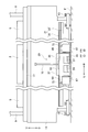
- FIG. 4 is an enlarged front view of the periphery of the foot switch device of the press brake according to the embodiment of the present invention.
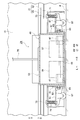
- FIG. 5 is an enlarged side view of the periphery of the foot switch device of the press brake according to the embodiment of the present invention.
- 6 (a) and 6 (b) are diagrams for explaining the characterizing portion of the foot switch device of the press brake according to the embodiment of the present invention.
- FIG. 6 (a) shows the state before the lowering foot pedal or the raising foot pedal is depressed
- FIG. 6 (b) shows the state where the lowering foot pedal or the raising foot pedal is depressed. .
- the “longitudinal direction” refers to one in the horizontal direction, that is, in the longitudinal direction of the press brake, and in the embodiment of the present invention, to the lateral direction.
- the “depth direction” refers to one in the horizontal direction, that is, the depth direction of the press brake, and in the embodiment of the present invention, the front-rear direction.
- FF forward
- FR backward
- L left
- R right
- U is upward
- D is downward. Point to each.
- the press brake 1 is a plate-like work (the punch die) and the lower die (die die) 5 cooperate with each other. It is a processing machine that performs bending on a sheet metal (W).
- the press brake 1 further includes a main body frame 7.
- the main body frame 7 includes a plurality of side plates 9 that are spaced apart and opposed in the length direction (left and right direction) and a plurality of side plates 9 And only one connecting member 11 shown).
- Each side plate 9 is installed to be adjustable in height with respect to the floor surface F by a level bolt 13.
- a lower table 15 extending in the length direction (left and right direction) is provided.
- a lower mold holder 17 is provided which detachably holds a plurality of lower molds 5 spaced apart in the lengthwise direction.
- an upper table 19 extending in the length direction is provided at the upper part of the main body frame 7 so as to be vertically movable (movable in the vertical direction), and the upper table 19 is vertically opposed to the lower table 15 .
- an upper mold holder 21 for detachably holding a plurality of upper molds 3 spaced apart in the lengthwise direction is provided.
- a hydraulic cylinder 23 is provided on the upper portion of each side plate 9 as a lifting actuator for lifting and lowering the upper table 19.
- An electric motor (not shown) may be used instead of the hydraulic cylinder 23 as the lift actuator.
- a plurality of processing stations S for performing the step bending process are formed by the plurality of upper molds 3 and the plurality of lower molds 5. Further, on the back side of the lower table 15, a back gauge device 25 for positioning the work W in the depth direction (front-rear direction) with respect to the lower mold 5 at each processing station S is provided.
- the back gauge device 25 has a butt member 27 that can butt the end face of the workpiece W, and the butt member 27 is positionally adjustable in the depth direction.
- the press brake 1 includes a movable foot switch device 29 for moving the upper table 19 up and down by a stepping operation by the operator M.
- a movable foot switch device 29 for moving the upper table 19 up and down by a stepping operation by the operator M.
- the concrete composition of foot switch device 29 concerning an embodiment of the present invention is as follows.
- a guide member 31 extending in the length direction (left and right direction) is provided at the lower part of the lower table 15.
- the guide member 31 has a guide main body portion 33 provided at the lower part of the lower table 15 and a rail portion 35 provided on the front surface (front surface) of the guide main body portion 33 and formed in a U shape having an open front side. doing.
- the guide member 31 may be provided on another member (not shown) such as a fixed frame disposed on the front side of the lower table 15 instead of the lower portion of the lower table 15.
- a slide member 37 is provided on the guide member 31 so as to be movable in the longitudinal direction.
- the slide member 37 has a guided portion 39 which is guided by the rail portion 35 of the guide member 31 so as to be movable in the longitudinal direction, and a slide main body portion 41 provided on the guided portion 39.
- the slide main body portion 41 is configured to be adjustable in height with respect to the guided portion 39 by a plurality of adjustment bolts 43.
- the pedal case 45 is provided on the slide member 37 so as to be vertically swingable via a plurality of hinges 47 as hinge members.
- the pedal case 45 moves in the length direction (left and right direction) together with the slide member 37 by manual operation (manual force) such as pushing by the foot Mf of the worker M.
- the pedal case 45 is integrally erected on the upper surface of the support base 49 provided on the slide member 37 so as to be vertically swingable through the plurality of hinges 47 and on the upper surface of the support base 49 and has a length A pair of support wall portions 51 opposed in the direction, and a case main body portion 53 provided between the pair of support wall portions 51 on the upper surface of the support base portion 49 and opening on the front side (front side).
- the pedal case 45 has a stopper portion (contact portion) 55 formed on the front side of the support base portion 49 and capable of contacting the floor surface F.
- the height adjustment of the slide main body portion 41 relative to the guided portion 39 enables the pedal case 45 to adjust the height relative to the guide member 31 (the lower table 15). It is configured to be possible.
- a lowering foot pedal 57 and a raising foot pedal 59 which can be stepped on are provided.
- the upper table 19 is lowered by controlling the drive of the pair of hydraulic cylinders 23 by the stepping operation of the lowering foot pedal 57.
- the raising operation of the upper table 19 is performed.
- the upper table 19 may be automatically lifted.
- a movable bracket 61 is provided on each support wall 51 of the pedal case 45 so as to be vertically movable via a plurality of guide bolts 63 and a plurality of elongated holes 65.
- Each movable bracket 61 is provided with a caster 67 as a rolling element (rotating body) that rolls (rotates) on the floor surface F along the length direction.
- casters 67 are provided on the left and right sides (both sides in the length direction) of the pedal case 45 so as to be vertically movable via the movable bracket 61 and the like.
- Each caster 67 receives the weight acting on the pedal case 45 (including the weight of the pedal case 45, the weight of the lowering foot pedal 57, and the weight of the raising foot pedal 59). Note that instead of using the casters 67 as the rolling elements, rollers (not shown) other than the casters 67 or a flow ball (not shown) may be used.
- a cover 69 that covers the upper portions of the movable bracket 61 and the caster 67 is integrally provided on each of the support wall portions 51 of the pedal case 45.
- a movable bracket 61 in other words, a coil spring 71 as a biasing member for biasing the caster 67 downward is provided via a support bolt 73.
- the foot switch device 29 raises each caster 67 relative to the pedal case 45 against the biasing force of the coil spring 71 when the lowering foot pedal 57 or the raising foot pedal 59 is depressed.
- the stopper portion (contact portion) 55 of the pedal case 45 is configured to be in contact with the floor surface F.
- a spring (not shown) other than the coil spring 71 or an elastic member (not shown) such as a rubber member may be used.
- a post 75 which can be gripped by the operator M is provided upright on the upper surface of the case body 53 of the pedal case 45.
- the post 75 is a member for assisting movement of the pedal case 45 in the longitudinal direction (left and right direction) manually (manually).
- step bend bending in a plurality of processing stations S, the following is performed.
- the first processing station (the first bending station) S is moved by moving the pedal case 45 together with the slide member 37 in the longitudinal direction (left / right direction) manually (manually) such as pushing by the foot Mf of the worker M. Position in the corresponding position.
- the end face of the workpiece W is abutted against the abutment member 27 to position the workpiece W in the depth direction (front-rear direction) with respect to the lower mold 5.
- the upper table 19 is moved up and down by controlling the drive of the pair of hydraulic cylinders 23 by stepping on the lowering foot pedal 57 and the raising foot pedal 59 (or only the lowering foot pedal 57).
- the first bending processing can be performed on the work W by the cooperation of the upper mold 3 and the lower mold 5.
- the pedal case 45 is moved along with the slide member 37 in the length direction manually (manually) based on the bending order of the work W, and the next and subsequent processing stations (next The processing station is positioned at a position corresponding to a processing station S that performs bending processing thereafter.
- the end face of the workpiece W is abutted against the abutment member 27 to position the workpiece W in the depth direction with respect to the lower mold 5.
- the upper table 19 is moved up and down by controlling the drive of the pair of hydraulic cylinders 23 by stepping on the lowering foot pedal 57 and the raising foot pedal 59 (or only the lowering foot pedal 57).
- bending work can be performed on the workpiece W by the cooperation of the upper mold 3 and the lower mold 5.
- the pedal case 45 is vertically swingable on the slide member 37 via the plurality of hinges 47 and has the stopper portion 55 capable of contacting the floor surface F.
- the casters 67 respectively provided movably in the vertical direction on both sides (right and left sides) in the longitudinal direction of the pedal case 45 are biased downward by the coil spring 71 with respect to the pedal case 45.
- the foot switch device 29 raises each caster 67 relative to the pedal case 45 against the biasing force of the coil spring 71 when the lowering foot pedal 57 or the raising foot pedal 59 is depressed.
- the stopper portion 55 of the pedal case 45 is configured to be in contact with the floor surface F.
- each caster 67 is sufficiently grounded to the floor F, and the pedal case 45 is extended.
- the rolling state of each caster 67 can be stabilized.
- the pedal case 45 is configured to be vertically swingable in the slide member 37 via the plurality of hinges 47, even if the floor surface F has unexpected unevenness, the pedal case 45 is in the length direction. When moving the pedal case 45, the unevenness can be absorbed by the swing of the pedal case 45.
- the pedal case 45 can be lengthened by pressing or pulling in a state in which the post 75 is gripped in addition to pressing by the foot Mf of the operator M. It can be moved in the longitudinal direction.
- the pedal case 45 is prevented from slightly moving in the longitudinal direction with the slide member 37. can do. Therefore, according to the embodiment of the present invention, when the operator M steps on the lowering foot pedal 57 or the like, the work W can be bent in a stable posture without losing the balance, and bending Stable processing accuracy can be maintained.
- the pedal case 45 can be moved in the length direction, and the operability of the foot switch device 29 can be improved.
- the pedal case 45 can be moved in the length direction by pushing or pulling in a state in which the post 75 is held, the operability of the foot switch device 29 can be further improved.
Landscapes
- Engineering & Computer Science (AREA)
- Mechanical Engineering (AREA)
- Bending Of Plates, Rods, And Pipes (AREA)
- Presses And Accessory Devices Thereof (AREA)
Abstract
L'invention concerne une presse plieuse permettant d'effectuer une flexion d'une pièce (W) dans une attitude stable et de maintenir de manière stable la précision de traitement de la flexion. Dans un dispositif de commutation par le pied (29) de la presse plieuse, un boîtier de pédale (45) est conçu pour pouvoir pivoter dans une direction verticale par rapport à un élément coulissant (37) et comprend une partie butée (55) entrant en contact avec une surface de sol (F). Des roulettes (67) disposées de façon mobile dans la direction verticale sur les deux côtés dans la direction de la longueur du boîtier de pédale (45) sont poussées au moyen d'un ressort hélicoïdal (71) dans une direction vers le bas par rapport au boîtier de pédale (45). Le dispositif de commutation par le pied (29) est conçu de telle sorte que, lorsqu'une pédale d'abaissement (57) ou une pédale d'élévation (59) est enfoncée, les roulettes (67) s'élèvent par rapport au boîtier de pédale (45) contre la force de poussée du ressort hélicoïdal (71), et la partie butée (55) du boîtier de pédale (45) entre en contact avec la surface de sol (F).
Priority Applications (1)
| Application Number | Priority Date | Filing Date | Title |
|---|---|---|---|
| CN201880067435.4A CN111246994B (zh) | 2017-10-16 | 2018-10-16 | 弯扳机 |
Applications Claiming Priority (2)
| Application Number | Priority Date | Filing Date | Title |
|---|---|---|---|
| JP2017-200069 | 2017-10-16 | ||
| JP2017200069A JP6450820B1 (ja) | 2017-10-16 | 2017-10-16 | プレスブレーキ |
Publications (1)
| Publication Number | Publication Date |
|---|---|
| WO2019078200A1 true WO2019078200A1 (fr) | 2019-04-25 |
Family
ID=64960394
Family Applications (1)
| Application Number | Title | Priority Date | Filing Date |
|---|---|---|---|
| PCT/JP2018/038472 Ceased WO2019078200A1 (fr) | 2017-10-16 | 2018-10-16 | Presse plieuse |
Country Status (3)
| Country | Link |
|---|---|
| JP (1) | JP6450820B1 (fr) |
| CN (1) | CN111246994B (fr) |
| WO (1) | WO2019078200A1 (fr) |
Families Citing this family (1)
| Publication number | Priority date | Publication date | Assignee | Title |
|---|---|---|---|---|
| JP6745940B1 (ja) * | 2019-04-17 | 2020-08-26 | 株式会社アマダ | プレスブレーキ |
Citations (3)
| Publication number | Priority date | Publication date | Assignee | Title |
|---|---|---|---|---|
| JP2002292430A (ja) * | 2001-04-02 | 2002-10-08 | Amada Co Ltd | ワーク位置決め位置 |
| JP3744593B2 (ja) * | 1996-05-08 | 2006-02-15 | 株式会社アマダ | プレスブレーキ用移動式フットペダル |
| JP2016215230A (ja) * | 2015-05-19 | 2016-12-22 | 株式会社アマダホールディングス | 曲げ加工装置 |
Family Cites Families (8)
| Publication number | Priority date | Publication date | Assignee | Title |
|---|---|---|---|---|
| DE4314104A1 (de) * | 1993-04-29 | 1994-11-03 | Miele & Cie | Einrichtung zur Befestigung eines einen Arbeitshub auslösenden Fußpedals an einer Stanz- oder Preßmaschine, insbesondere einer Gesenkbiegepresse |
| US5586465A (en) * | 1994-11-22 | 1996-12-24 | Alcini; Raymond R. | Press brake controller positioning system |
| JP4257885B2 (ja) * | 2000-10-26 | 2009-04-22 | 株式会社アマダ | 曲げ加工装置 |
| JP2004058070A (ja) * | 2002-07-25 | 2004-02-26 | Amada Co Ltd | 曲げ加工装置 |
| JP2004058069A (ja) * | 2002-07-25 | 2004-02-26 | Amada Co Ltd | 曲げ加工装置 |
| JP2006334600A (ja) * | 2005-05-31 | 2006-12-14 | Amada Co Ltd | 曲げ加工装置 |
| JP6408848B2 (ja) * | 2014-10-01 | 2018-10-17 | 株式会社アマダホールディングス | 曲げ加工装置 |
| JP6574709B2 (ja) * | 2016-01-15 | 2019-09-11 | 株式会社アマダホールディングス | 移動式フットスイッチ装置及び曲げ加工機 |
-
2017
- 2017-10-16 JP JP2017200069A patent/JP6450820B1/ja active Active
-
2018
- 2018-10-16 WO PCT/JP2018/038472 patent/WO2019078200A1/fr not_active Ceased
- 2018-10-16 CN CN201880067435.4A patent/CN111246994B/zh active Active
Patent Citations (3)
| Publication number | Priority date | Publication date | Assignee | Title |
|---|---|---|---|---|
| JP3744593B2 (ja) * | 1996-05-08 | 2006-02-15 | 株式会社アマダ | プレスブレーキ用移動式フットペダル |
| JP2002292430A (ja) * | 2001-04-02 | 2002-10-08 | Amada Co Ltd | ワーク位置決め位置 |
| JP2016215230A (ja) * | 2015-05-19 | 2016-12-22 | 株式会社アマダホールディングス | 曲げ加工装置 |
Also Published As
| Publication number | Publication date |
|---|---|
| CN111246994A (zh) | 2020-06-05 |
| JP6450820B1 (ja) | 2019-01-09 |
| JP2019072734A (ja) | 2019-05-16 |
| CN111246994B (zh) | 2021-01-26 |
Similar Documents
| Publication | Publication Date | Title |
|---|---|---|
| US11331817B2 (en) | Maintenance apparatus of robot and maintenance method of robot | |
| KR20100129992A (ko) | 디스태킹 행거 장치 | |
| CN101208175A (zh) | 对接熔接板材的定位方法及装置 | |
| KR20090109003A (ko) | 차량용 타이어 로딩장치 | |
| WO2019078200A1 (fr) | Presse plieuse | |
| CN217750418U (zh) | 一种不锈钢门加工用切割设备 | |
| JP2010162558A (ja) | 曲げ加工機 | |
| JP6401620B2 (ja) | 曲げ加工方法、バックゲージ装置、及びプレスブレーキ | |
| US10823328B2 (en) | Press brake in which height position of operation panel is adjustable in sitting state | |
| JP2002143929A (ja) | 可搬式溝形材用矯正機 | |
| JP2022034814A (ja) | ワーク搬送台車及び加工システム | |
| JP4523983B2 (ja) | しごき加工装置 | |
| JPH02197331A (ja) | ヘミング装置 | |
| JP2016215230A (ja) | 曲げ加工装置 | |
| JP6745940B1 (ja) | プレスブレーキ | |
| CN106734689A (zh) | 一种用于汽车板材拼焊的落料模具 | |
| JPH0824964B2 (ja) | 折曲げ機のバックゲージ装置 | |
| CN220426403U (zh) | 一种钢板折弯机 | |
| JP2665234B2 (ja) | シャーリングマシン | |
| JP2019118913A (ja) | パネルベンダー及びその動作方法 | |
| JP7474643B2 (ja) | プレスブレーキ | |
| US3958436A (en) | Dynamically controlled forming by drawing machine | |
| JP2000301258A (ja) | パンチプレス | |
| JP2577103Y2 (ja) | 形鋼加工機におけるワーク搬送装置 | |
| JP2017192971A (ja) | 作業テーブル装置及び曲げ加工機 |
Legal Events
| Date | Code | Title | Description |
|---|---|---|---|
| 121 | Ep: the epo has been informed by wipo that ep was designated in this application |
Ref document number: 18867730 Country of ref document: EP Kind code of ref document: A1 |
|
| NENP | Non-entry into the national phase |
Ref country code: DE |
|
| 122 | Ep: pct application non-entry in european phase |
Ref document number: 18867730 Country of ref document: EP Kind code of ref document: A1 |