WO2019078256A1 - Actionneur - Google Patents
Actionneur Download PDFInfo
- Publication number
- WO2019078256A1 WO2019078256A1 PCT/JP2018/038677 JP2018038677W WO2019078256A1 WO 2019078256 A1 WO2019078256 A1 WO 2019078256A1 JP 2018038677 W JP2018038677 W JP 2018038677W WO 2019078256 A1 WO2019078256 A1 WO 2019078256A1
- Authority
- WO
- WIPO (PCT)
- Prior art keywords
- metal
- press
- gear
- shaft
- actuator
- Prior art date
- Legal status (The legal status is an assumption and is not a legal conclusion. Google has not performed a legal analysis and makes no representation as to the accuracy of the status listed.)
- Ceased
Links
Images





Classifications
-
- F—MECHANICAL ENGINEERING; LIGHTING; HEATING; WEAPONS; BLASTING
- F02—COMBUSTION ENGINES; HOT-GAS OR COMBUSTION-PRODUCT ENGINE PLANTS
- F02B—INTERNAL-COMBUSTION PISTON ENGINES; COMBUSTION ENGINES IN GENERAL
- F02B37/00—Engines characterised by provision of pumps driven at least for part of the time by exhaust
- F02B37/12—Control of the pumps
- F02B37/18—Control of the pumps by bypassing exhaust from the inlet to the outlet of turbine or to the atmosphere
-
- F—MECHANICAL ENGINEERING; LIGHTING; HEATING; WEAPONS; BLASTING
- F16—ENGINEERING ELEMENTS AND UNITS; GENERAL MEASURES FOR PRODUCING AND MAINTAINING EFFECTIVE FUNCTIONING OF MACHINES OR INSTALLATIONS; THERMAL INSULATION IN GENERAL
- F16H—GEARING
- F16H1/00—Toothed gearings for conveying rotary motion
- F16H1/02—Toothed gearings for conveying rotary motion without gears having orbital motion
- F16H1/04—Toothed gearings for conveying rotary motion without gears having orbital motion involving only two intermeshing members
- F16H1/06—Toothed gearings for conveying rotary motion without gears having orbital motion involving only two intermeshing members with parallel axes
-
- F—MECHANICAL ENGINEERING; LIGHTING; HEATING; WEAPONS; BLASTING
- F16—ENGINEERING ELEMENTS AND UNITS; GENERAL MEASURES FOR PRODUCING AND MAINTAINING EFFECTIVE FUNCTIONING OF MACHINES OR INSTALLATIONS; THERMAL INSULATION IN GENERAL
- F16H—GEARING
- F16H57/00—General details of gearing
- F16H57/04—Features relating to lubrication or cooling or heating
-
- H—ELECTRICITY
- H02—GENERATION; CONVERSION OR DISTRIBUTION OF ELECTRIC POWER
- H02K—DYNAMO-ELECTRIC MACHINES
- H02K7/00—Arrangements for handling mechanical energy structurally associated with dynamo-electric machines, e.g. structural association with mechanical driving motors or auxiliary dynamo-electric machines
- H02K7/10—Structural association with clutches, brakes, gears, pulleys or mechanical starters
- H02K7/116—Structural association with clutches, brakes, gears, pulleys or mechanical starters with gears
-
- Y—GENERAL TAGGING OF NEW TECHNOLOGICAL DEVELOPMENTS; GENERAL TAGGING OF CROSS-SECTIONAL TECHNOLOGIES SPANNING OVER SEVERAL SECTIONS OF THE IPC; TECHNICAL SUBJECTS COVERED BY FORMER USPC CROSS-REFERENCE ART COLLECTIONS [XRACs] AND DIGESTS
- Y02—TECHNOLOGIES OR APPLICATIONS FOR MITIGATION OR ADAPTATION AGAINST CLIMATE CHANGE
- Y02T—CLIMATE CHANGE MITIGATION TECHNOLOGIES RELATED TO TRANSPORTATION
- Y02T10/00—Road transport of goods or passengers
- Y02T10/10—Internal combustion engine [ICE] based vehicles
- Y02T10/12—Improving ICE efficiencies
Definitions
- the present disclosure relates to an actuator that drives a supercharger control valve.
- an actuator connected to a supercharging pressure control valve via, for example, a link mechanism and the like to control the supercharging pressure by adjusting the valve opening.
- the actuator disclosed in Patent Document 1 decelerates the rotation of the motor by the decelerating unit and outputs it from the output shaft.
- the gear of the speed reduction unit is made of resin and is rotatably supported by a metal shaft.
- the boost pressure control valve regulates the amount of hot exhaust entering the turbocharger. Therefore, the mounting environment of the actuator becomes high temperature. As described above, in the case of a high temperature environment, if the linear expansion difference between the gear of the reduction portion of the actuator and the shaft supporting the shaft is large, the clearance between the sliding surfaces of both members becomes large and the gear is inclined. If the force applied to the supercharging pressure control valve acts on the gear through the link mechanism due to exhaust pulsation, the gear can not be stably rotated, and the gear tooth surface and sliding surface may be unevenly worn. There is.
- This indication is made in view of the above-mentioned point, and the purpose is to provide an actuator with which endurance improvement was aimed at.
- the actuator of the present disclosure includes a motor, an output shaft, a reduction unit, a metal shaft, and a housing.
- the speed reduction unit includes one or more metal gears to reduce the speed of rotation of the motor and transmit it to the output shaft.
- the metal shaft is fitted in the axial center hole of the metal gear, and rotatably supports the metal gear.
- the housing contains the motor and the reduction gear, and supports the output shaft and the metal shaft.
- One of the metal gear and the metal shaft is provided with a lubricating coating on a portion sliding with at least the other.
- the linear expansion difference of both members becomes small by comprising the gear of a deceleration part, and the shaft which carries out the shaft support of it from the metal of the same material.
- the clearance between the sliding surfaces of both members at the time of use in a high temperature environment becomes smaller, and the inclination of the gear can be suppressed. Therefore, even if the force due to the exhaust pulsation acts on the gear, the gear is stably rotated, so that it is possible to suppress the partial wear of the tooth surface and the sliding surface of the gear. Therefore, the durability of the actuator is improved.
- the actuator of the present disclosure since the lubricating coating is provided, wear due to sliding between the metal gear and the metal shaft can be reduced without providing a bearing component. In addition, since there is no bearing component, it is possible to avoid an increase in diameter of the gear and an increase in size of the actuator due to the increase in diameter.
- FIG. 1 is a schematic view of an intake and exhaust portion of an engine to which an actuator according to a first embodiment is applied
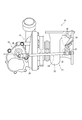
- Fig. 2 is an explanatory view of a supercharger
- FIG. 3 is a perspective view of the actuator
- FIG. 4 is a top view of the actuator
- 5 is a cross-sectional view taken along the line V-V of FIG. 6 is a cross-sectional view taken along line VI-VI of FIG. 7 is a view showing a state in which the second housing portion etc. of the actuator of FIG. 4 is removed
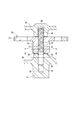
- FIG. 8 is a view showing a first intermediate gear and a metal shaft
- FIG. 11 is a view showing a first intermediate gear and a metal shaft of an actuator according to a second embodiment.
- the actuator 10 according to the first embodiment is applied to an engine 11 which is a power source for traveling a vehicle.
- the engine 11 is provided with an intake passage 12 for introducing intake air into the cylinder of the engine 11 and an exhaust passage 13 for discharging exhaust gas generated in the cylinder to the atmosphere.
- An intake compressor 15 of the turbocharger 14 and a throttle valve 16 for adjusting the amount of intake air supplied to the engine 11 are provided in the middle of the intake passage 12.
- an exhaust turbine 17 of the supercharger 14 and a catalyst 18 for purifying exhaust gas are provided in the middle of the exhaust passage 13.
- the catalyst 18 is a well-known three-way catalyst adopting a monolithic structure, and by raising the temperature to an activation temperature, the harmful substances contained in the exhaust gas are purified by an oxidation action and a reduction action.
- the exhaust turbine 17 includes a turbine wheel 21 rotationally driven by exhaust gas discharged from the engine 11, and a spiral-shaped turbine housing 22 accommodating the turbine wheel 21.
- the intake compressor 15 includes a compressor wheel 23 that rotates in response to the rotational force of the turbine wheel 21 and a spiral compressor housing 24 that accommodates the compressor wheel 23.
- the turbine housing 22 is provided with a bypass passage 25 for passing exhaust gas around the turbine wheel 21.
- the bypass passage 25 leads the exhaust gas flowing into the turbine housing 22 directly to the exhaust outlet of the turbine housing 22.
- the bypass passage 25 can be opened and closed by the waste gate valve 26.
- the waste gate valve 26 is a swing valve rotatably supported by a valve shaft 27 inside the turbine housing 22.
- the turbocharger 14 is provided with an actuator 10.
- the actuator 10 is attached to an intake compressor 15 remote from the exhaust turbine 17 for the purpose of avoiding the thermal influence of the exhaust gas.
- the supercharger 14 is provided with a link mechanism 29 for transmitting the output of the actuator 10 to the waste gate valve 26.
- the link mechanism 29 is a so-called four-bar link, and the actuator lever 31 which is rotationally operated by the actuator 10, the valve lever 32 coupled to the valve shaft 27, and the rotational torque applied to the actuator lever 31 And a rod 33 for transmitting to the lever 32.
- the actuator 10 is controlled by an ECU (engine control unit) 34 mounted with a microcomputer. Specifically, the ECU 34 adjusts the opening degree of the waste gate valve 26 at high rotation of the engine 11 or the like to control the supercharging pressure by the turbocharger 14. Further, the ECU 34 warms up the catalyst 18 by fully opening the waste gate valve 26 when the temperature of the catalyst 18 has not reached the activation temperature, such as immediately after a cold start. As a result, the high temperature exhaust gas which has not been deprived of heat by the turbine wheel 21 can be introduced to the catalyst 18, and the catalyst 18 can be warmed up promptly.
- the ECU 34 engine control unit 34 mounted with a microcomputer. Specifically, the ECU 34 adjusts the opening degree of the waste gate valve 26 at high rotation of the engine 11 or the like to control the supercharging pressure by the turbocharger 14. Further, the ECU 34 warms up the catalyst 18 by fully opening the waste gate valve 26 when the temperature of the catalyst 18 has not reached the activation temperature, such as immediately after a cold start. As a result
- the actuator 10 includes a housing 35 attached to the intake compressor 15, a motor 36 assembled to the housing 35, a speed reduction unit 37, an output shaft 38, and a rotation angle sensor 39.
- the housing 35 has a first housing portion 41 and a second housing portion 42.
- the second housing portion 42 is fastened to the first housing portion 41 by a fastening member 43.
- the first housing portion 41 forms a housing space 44 together with the second housing portion 42.
- the first housing portion 41 and the second housing portion 42 are made of a metal material such as an aluminum alloy, for example, and are die-cast.
- the motor 36 is accommodated in a housing 35. Specifically, the motor 36 is inserted into a motor insertion hole 46 formed in the first housing portion 41, and is fixed to the first housing portion 41 by a screw 47.
- the motor 36 may be, for example, a well-known direct current motor or a well-known stepping motor regardless of its type.
- the output shaft 38 is rotatably supported by a bearing 48 provided in the first housing portion 41 and a bearing 49 provided in the second housing portion 42.
- One end of the output shaft 38 extends out of the housing 35.
- the actuator lever 31 is fixed to the output shaft outside the housing 35.
- the reduction gear unit 37 is a parallel shaft reduction gear that decelerates the rotation of the motor 36 and transmits it to the output shaft 38, and includes the pinion gear 51, the first intermediate gear 52, and the second intermediate gear.
- a gear 53 and a final gear 54 are provided.
- the pinion gear 51 is fixed to a motor shaft 55 of the motor 36.
- the first intermediate gear 52 has a first large diameter external gear 57 engaged with the pinion gear 51 and a first small diameter external gear 58 smaller than the first large diameter external gear 57.
- the second intermediate gear 53 has a second large diameter external gear 62 engaged with the first small diameter external gear 58 and a second small diameter external gear 63 smaller than the second large diameter external gear 62.
- the final gear 54 is fixed to the output shaft 38 and meshes with the second small diameter external tooth portion 63.
- the rotation angle sensor 39 is a non-contact type sensor that detects the rotation angle of the output shaft 38, and includes a magnetic circuit unit 64 and a detection unit 65.
- the magnetic circuit unit 64 includes magnets 66 and 67 as magnetic flux generating units and yokes 68 and 69 as magnetic flux transmitting units.
- the magnets 66 and 67 and the yokes 68 and 69 form an arc-shaped closed magnetic circuit in the axial direction of the output shaft 38.
- the magnetic circuit section 64 is held by a nonmagnetic magnetic circuit holding member 73 and rotates integrally with the output shaft 38.
- the detection unit 65 is, for example, a Hall IC, and is disposed inside the closed magnetic circuit of the magnetic circuit unit 64.
- the detection unit 65 is molded in the wire holding member 71 made of an insulator, and is fixed to the housing 35.
- the basic applications and functions of the magnetic circuit unit 64 and the detection unit 65 are the same as those disclosed in Japanese Patent Laid-Open No. 2014-126548.
- the rotation angle of the output shaft 38 detected by the rotation angle sensor 39 is output to the ECU 34 (see FIG. 1).
- the gears of the reduction gear 37 that is, the pinion gear 51, the first intermediate gear 52, the second intermediate gear 53 and the final gear 54 are metal gears and made of iron-based sintered metal. .
- metal gear when describing a plurality of gears of the reduction gear 37, it will be appropriately described as "metal gear”.
- the actuator 10 includes metal shafts 75 and 76.
- the metal shaft 75 is fitted in the axial center hole 77 of the first intermediate gear 52, and rotatably supports the first intermediate gear 52.
- the metal shaft 76 is fitted in the axial center hole 78 of the second intermediate gear 53, and rotatably supports the second intermediate gear 53.
- the metal shaft 75 and the metal shaft 76 have the same configuration. Below, these are represented and the metal shaft 75 is demonstrated. As shown in FIG. 8, the metal shaft 75 has a press-fit portion 81, an intermediate portion 82, a coated portion 83 and a fitting portion 84.
- the press-fit portion 81 is an end portion of the metal shaft 75 on the side of the first housing portion 41, and is press-fit into the press-fit hole 85 of the first housing portion 41.
- the fitting portion 84 is the other end portion of the metal shaft 75 on the second housing portion 42 side, and is fitted in the fitting hole 86 of the second housing portion 42.
- the coating portion 83 includes a portion that slides on the first intermediate gear 52.
- the coating 83 is provided with a lubricating coating 87.
- the "lubricant film” is a solid lubricant formed into a film.
- the lubricating coating 87 is shown by a grid pattern of broken lines.
- the lubricating film 87 provided on the film portion 83 is required to have a certain level of lubricating performance or more. The lubricating performance is determined by the thickness and hardness of the lubricating coating 87.
- the lubricating coating 87 is provided other than the press-fit portion 81. That is, the lubricant film 87 is not provided in the press-fit portion 81.
- the lubricating coating 87 is provided on the fitting portion 84 and the coating portion 83.
- the lubricating film 87 is a DLC (Diamond-Like Carbon) film.
- the middle portion 82 is located between the press-fit portion 81 and the coating portion 83, and no lubrication performance is required. That is, even if the middle portion 82 is provided with a lubricating film, the film does not need to have a film thickness and hardness for obtaining a predetermined lubricating performance or more.
- a chamfer 93 is formed at the end of the shaft center hole 77 on the press-in hole 85 side.
- the sliding surface 92 of the axial center hole 77 is a portion of the axial center hole 77 other than the chamfered portion 91.
- a chamfer 91 is formed at an end of the press-in hole 85 on the first intermediate gear 52 side.
- the press-fit surface 94 of the press-fit hole 85 is a portion of the inner wall surface of the press-fit hole 85 other than the chamfer 93.
- a washer 95 is provided between the first intermediate gear 52 and the first housing portion 41 (that is, between the axial center hole 77 and the press-in hole 85).
- An axial distance from an end on the first intermediate gear 52 side of the press-fit surface 94 of the press-in hole 85 to an end on the press-in hole 85 side of the sliding face 92 of the axial center hole 77 is A.
- the axial length of the intermediate portion 82 is B.
- the axial distance A and the axial length B are in the relationship of the following equation (1).
- the metal shaft 75 is made of a material having a relatively high surface hardness, and has a surface hardness higher than, for example, the output shaft 38.
- the output shaft 38 may be made of stainless steel such as SUS430 or SUS304 as long as it has the strength necessary to be bearing-supported.
- the metal shaft 75 is made of, for example, heat-treated tool steel SKH 51 (HRC 60 or more) or the like in order to prevent peeling of the lubricating coating 87 by suppressing deformation.
- a lubricant is applied between the coating 83 and the first intermediate gear 52.
- the lubricant is, for example, lubricating grease or lubricating oil.
- the actuator 10 includes the motor 36, the output shaft 38, the speed reduction unit 37, the metal shafts 75 and 76, and the housing 35.
- the speed reducing portion 37 includes a first intermediate gear 52 and a second intermediate gear 53 which are metal gears.
- the metal shafts 75, 76 are fitted in the axial center holes 77, 78 of the intermediate gears 52, 53, and rotatably support the intermediate gears 52, 53.
- the housing 35 accommodates the motor 36 and the reduction gear 37, and supports the output shaft 38 and the metal shafts 75, 76.
- a lubricating coating 87 is provided on the metal shafts 75 and 76 at least in a portion that slides with the intermediate gears 52 and 53.
- the intermediate gears 52, 53 and the metal shafts 75, 76 supporting the shafts are formed from metal of the same material.
- the clearance between the sliding surfaces of both members at the time of use under high temperature environment becomes smaller, and the inclination of the intermediate gears 52, 53 can be suppressed. . Therefore, even if the force due to the exhaust pulsation acts on the intermediate gears 52, 53, they rotate stably, so that the partial wear of the tooth surfaces and the sliding surfaces of the intermediate gears 52, 53 can be suppressed. Therefore, the durability of the actuator 10 is improved.
- the lubricant film 87 is provided in the actuator 10 as described above, wear due to sliding between the intermediate gears 52, 53 and the metal shafts 75, 76 can be reduced without providing bearing parts. it can.
- there is no bearing component it is possible to avoid the increase in diameter of the intermediate gears 52 and 53 and the increase in size of the actuator 10 due to this.
- the metal shafts 75 and 76 have the press-fit portions 81 press-fit into the press-fit holes 85 of the first housing portion 41.
- the lubricating coating 87 is provided other than the press-fit portion 81.
- the metal shafts 75 and 76 have a surface hardness higher than that of the output shaft 38. As described above, by not providing the coating on the press-in portion 81 which is not required for sliding, the manufacturing cost can be reduced, and the press-in holding force of the metal shafts 75 and 76 can be increased. Further, peeling of the lubricating coating 87 can be suppressed by increasing the surface hardness of the metal shafts 75 and 76 to suppress deformation.
- the metal shafts 75 and 76 are located between the press-fit portion 81, the coating portion 83 provided with the lubricating coating 87, the press-fitting portion 81 and the coating portion 83, and require lubricity performance. And an intermediate portion 82.
- the axial distance A and the axial length B are in the relationship of the equation (1).
- the intermediate portion 82 which does not require the lubricating performance, the accuracy of the jig used at the time of manufacture can be lowered. Therefore, the cost and man-hours for jig maintenance etc. are reduced, and the manufacturing cost is lowered.
- the lubricating film 87 is a DLC film. Thereby, the same low friction sliding as in the case of providing the bearing component can be realized by the lubricating coating 87.
- the intermediate gears 52, 53 have small diameter external teeth 58, 63 and large diameter external teeth 57, 62.
- the tooth root minimum width C and the radial distance D are in the relationship of the equation (1). This relationship is established by realizing low friction sliding by the lubricating coating 87 and omitting the bearing parts. Therefore, the outer diameters of the small diameter external teeth 58, 63 become small, and the actuator 10 can be miniaturized.
- a lubricant is applied between the metal shafts 75 and 76 and the intermediate gears 52 and 53.
- the sliding between the metal shafts 75 and 76 and the intermediate gears 52 and 53 is further reduced in friction, the wear of the bearing portion is reduced, and the durability of the actuator 10 is further improved.
- it has a damping effect on exhaust pulsation, and the wear of the shaft center holes 77 and 78 of the intermediate gears 52 and 53 and the lubricating coating 87 of the metal shafts 75 and 76 due to impact is suppressed.
- the metal shafts 101 and 102 are not provided with a coating. Instead, the intermediate gears 103, 104 are provided with a lubricating coating 105 on the portion sliding with the metal shafts 75, 76. Thus, the lubricating coating 105 may be provided on the sliding portion of the intermediate gears 103 and 104. Nevertheless, wear due to sliding between the intermediate gears 103 and 104 and the metal shafts 101 and 102 can be reduced without providing bearing parts.
- the lubricating coating may not be provided on the fitting portion of the metal shaft, but may be provided only on the coating. In short, the lubricating coating may be provided on a portion of one of the intermediate gear and the metal shaft that slides on the other.
- the lubricating film is not limited to the DLC film, and may be, for example, a titanium aluminum nitride film or a molybdenum disulfide film.
- the lubricating coating is a film formed of a solid lubricant such as, for example, graphite (graphite), polytetrafluoroethylene (PTFE), graphite fluoride, boron nitride, tungsten disulfide, melamine cyanurate, etc. It is also good.
- a solid lubricant such as, for example, graphite (graphite), polytetrafluoroethylene (PTFE), graphite fluoride, boron nitride, tungsten disulfide, melamine cyanurate, etc. It is also good.
- no lubricant may be applied between the intermediate gear and the metal shaft.
- the intermediate gear of the reduction gear portion may be made of other metals as well as the iron-based sintered metal.
- the metal shaft is not limited to the tool steel SKH51, and may be made of another metal.
- the intermediate gear and the metal shaft may be made of the same kind of metal and metal instead of different kinds of materials such as resin and metal.
- the metal shaft may be provided with a middle portion so that the presence or absence of the coating is switched between the press-in portion and the coating portion.
Landscapes
- Engineering & Computer Science (AREA)
- General Engineering & Computer Science (AREA)
- Mechanical Engineering (AREA)
- Power Engineering (AREA)
- Chemical & Material Sciences (AREA)
- Combustion & Propulsion (AREA)
- Supercharger (AREA)
- Gear Transmission (AREA)
- General Details Of Gearings (AREA)
- Connection Of Motors, Electrical Generators, Mechanical Devices, And The Like (AREA)
Abstract
L'invention concerne un actionneur (10) entraînant une soupape de commande de pression de suralimentation (26) pour un compresseur de suralimentation (14) et pourvu d'un moteur (36), d'un arbre de sortie (38), d'une section de réduction de vitesse (37), d'un arbre métallique (75, 76) et d'un boîtier (35). La section de réduction de vitesse (37) comprend un premier engrenage intermédiaire (52) et un second engrenage intermédiaire (53) qui sont des engrenages métalliques. L'arbre métallique (75, 76) est ajusté dans un trou d'axe (77, 78) dans l'engrenage intermédiaire (52, 53) et supporte de manière rotative l'engrenage intermédiaire (52, 53). Le boîtier (35) contient le moteur (36) et la section de réduction de vitesse (37), et supporte l'arbre de sortie (38) et l'arbre métallique (75, 76). L'arbre métallique (75, 76) est pourvu d'un revêtement lubrifiant (87) sur la partie de l'arbre métallique (75, 76) qui coulisse sur au moins l'engrenage intermédiaire (52, 53).
Applications Claiming Priority (2)
| Application Number | Priority Date | Filing Date | Title |
|---|---|---|---|
| JP2017203403A JP7006122B2 (ja) | 2017-10-20 | 2017-10-20 | アクチュエータ |
| JP2017-203403 | 2017-10-20 |
Publications (1)
| Publication Number | Publication Date |
|---|---|
| WO2019078256A1 true WO2019078256A1 (fr) | 2019-04-25 |
Family
ID=66174513
Family Applications (1)
| Application Number | Title | Priority Date | Filing Date |
|---|---|---|---|
| PCT/JP2018/038677 Ceased WO2019078256A1 (fr) | 2017-10-20 | 2018-10-17 | Actionneur |
Country Status (2)
| Country | Link |
|---|---|
| JP (1) | JP7006122B2 (fr) |
| WO (1) | WO2019078256A1 (fr) |
Cited By (1)
| Publication number | Priority date | Publication date | Assignee | Title |
|---|---|---|---|---|
| JP2022001739A (ja) * | 2020-06-19 | 2022-01-06 | 株式会社ミクニ | エンジンのスロットル装置 |
Citations (4)
| Publication number | Priority date | Publication date | Assignee | Title |
|---|---|---|---|---|
| JPS5939357U (ja) * | 1982-09-06 | 1984-03-13 | 三菱電機株式会社 | 歯車 |
| JPS6439966U (fr) * | 1987-09-03 | 1989-03-09 | ||
| US20120255379A1 (en) * | 2009-12-29 | 2012-10-11 | Kamtec Inc. | Actuator for vehicle |
| JP2016017174A (ja) * | 2014-07-11 | 2016-02-01 | 株式会社豊田中央研究所 | 摺動機械 |
-
2017
- 2017-10-20 JP JP2017203403A patent/JP7006122B2/ja not_active Expired - Fee Related
-
2018
- 2018-10-17 WO PCT/JP2018/038677 patent/WO2019078256A1/fr not_active Ceased
Patent Citations (4)
| Publication number | Priority date | Publication date | Assignee | Title |
|---|---|---|---|---|
| JPS5939357U (ja) * | 1982-09-06 | 1984-03-13 | 三菱電機株式会社 | 歯車 |
| JPS6439966U (fr) * | 1987-09-03 | 1989-03-09 | ||
| US20120255379A1 (en) * | 2009-12-29 | 2012-10-11 | Kamtec Inc. | Actuator for vehicle |
| JP2016017174A (ja) * | 2014-07-11 | 2016-02-01 | 株式会社豊田中央研究所 | 摺動機械 |
Cited By (1)
| Publication number | Priority date | Publication date | Assignee | Title |
|---|---|---|---|---|
| JP2022001739A (ja) * | 2020-06-19 | 2022-01-06 | 株式会社ミクニ | エンジンのスロットル装置 |
Also Published As
| Publication number | Publication date |
|---|---|
| JP7006122B2 (ja) | 2022-01-24 |
| JP2019078281A (ja) | 2019-05-23 |
Similar Documents
| Publication | Publication Date | Title |
|---|---|---|
| US20200217255A1 (en) | Actuator | |
| JP6311657B2 (ja) | 電動アクチュエータ | |
| US20010015195A1 (en) | Throttle apparatus for internal combustion engine | |
| US11319869B2 (en) | Actuator | |
| US20190072044A1 (en) | Link mechanism actuator for internal combustion engine | |
| JP2012163017A (ja) | バタフライバルブ | |
| US20200232401A1 (en) | Actuator | |
| WO2019078256A1 (fr) | Actionneur | |
| US20220403772A1 (en) | Actuator | |
| US5205248A (en) | Intake- and/or exhaust-valve timing control system for internal combustion engines | |
| JP2013143808A (ja) | 電動アクチュエータ | |
| US10851720B2 (en) | Actuator | |
| US9840942B2 (en) | Camshaft adjuster | |
| JP6933122B2 (ja) | アクチュエータ | |
| JP2004060595A (ja) | 可変吸気装置 | |
| JP6270382B2 (ja) | 排ガスターボチャージャ | |
| WO2022202423A1 (fr) | Pompe électrique | |
| JP2020112177A (ja) | アクチュエータ | |
| JP2020112178A (ja) | アクチュエータ | |
| WO2019225425A1 (fr) | Pompe à huile électrique | |
| JPH07119474A (ja) | 過給装置 | |
| JP2021134801A (ja) | アクチュエータ | |
| JP2021134803A (ja) | アクチュエータ | |
| US20200284296A1 (en) | Gear train of an actuator | |
| CN111771043A (zh) | 凸轮轴调节装置 |
Legal Events
| Date | Code | Title | Description |
|---|---|---|---|
| 121 | Ep: the epo has been informed by wipo that ep was designated in this application |
Ref document number: 18869104 Country of ref document: EP Kind code of ref document: A1 |
|
| NENP | Non-entry into the national phase |
Ref country code: DE |
|
| 122 | Ep: pct application non-entry in european phase |
Ref document number: 18869104 Country of ref document: EP Kind code of ref document: A1 |