WO2019078664A1 - Procédé et dispositif de traitement de signal vidéo - Google Patents
Procédé et dispositif de traitement de signal vidéo Download PDFInfo
- Publication number
- WO2019078664A1 WO2019078664A1 PCT/KR2018/012393 KR2018012393W WO2019078664A1 WO 2019078664 A1 WO2019078664 A1 WO 2019078664A1 KR 2018012393 W KR2018012393 W KR 2018012393W WO 2019078664 A1 WO2019078664 A1 WO 2019078664A1
- Authority
- WO
- WIPO (PCT)
- Prior art keywords
- block
- merge candidate
- current block
- spatial
- unit
- Prior art date
- Legal status (The legal status is an assumption and is not a legal conclusion. Google has not performed a legal analysis and makes no representation as to the accuracy of the status listed.)
- Ceased
Links
Images


Classifications
-
- H—ELECTRICITY
- H04—ELECTRIC COMMUNICATION TECHNIQUE
- H04N—PICTORIAL COMMUNICATION, e.g. TELEVISION
- H04N19/00—Methods or arrangements for coding, decoding, compressing or decompressing digital video signals
- H04N19/50—Methods or arrangements for coding, decoding, compressing or decompressing digital video signals using predictive coding
- H04N19/503—Methods or arrangements for coding, decoding, compressing or decompressing digital video signals using predictive coding involving temporal prediction
- H04N19/51—Motion estimation or motion compensation
- H04N19/513—Processing of motion vectors
- H04N19/517—Processing of motion vectors by encoding
- H04N19/52—Processing of motion vectors by encoding by predictive encoding
-
- H—ELECTRICITY
- H04—ELECTRIC COMMUNICATION TECHNIQUE
- H04N—PICTORIAL COMMUNICATION, e.g. TELEVISION
- H04N19/00—Methods or arrangements for coding, decoding, compressing or decompressing digital video signals
- H04N19/50—Methods or arrangements for coding, decoding, compressing or decompressing digital video signals using predictive coding
- H04N19/503—Methods or arrangements for coding, decoding, compressing or decompressing digital video signals using predictive coding involving temporal prediction
- H04N19/51—Motion estimation or motion compensation
- H04N19/573—Motion compensation with multiple frame prediction using two or more reference frames in a given prediction direction
-
- H—ELECTRICITY
- H04—ELECTRIC COMMUNICATION TECHNIQUE
- H04N—PICTORIAL COMMUNICATION, e.g. TELEVISION
- H04N19/00—Methods or arrangements for coding, decoding, compressing or decompressing digital video signals
- H04N19/50—Methods or arrangements for coding, decoding, compressing or decompressing digital video signals using predictive coding
- H04N19/503—Methods or arrangements for coding, decoding, compressing or decompressing digital video signals using predictive coding involving temporal prediction
- H04N19/51—Motion estimation or motion compensation
-
- H—ELECTRICITY
- H04—ELECTRIC COMMUNICATION TECHNIQUE
- H04N—PICTORIAL COMMUNICATION, e.g. TELEVISION
- H04N19/00—Methods or arrangements for coding, decoding, compressing or decompressing digital video signals
- H04N19/10—Methods or arrangements for coding, decoding, compressing or decompressing digital video signals using adaptive coding
- H04N19/102—Methods or arrangements for coding, decoding, compressing or decompressing digital video signals using adaptive coding characterised by the element, parameter or selection affected or controlled by the adaptive coding
- H04N19/115—Selection of the code volume for a coding unit prior to coding
-
- H—ELECTRICITY
- H04—ELECTRIC COMMUNICATION TECHNIQUE
- H04N—PICTORIAL COMMUNICATION, e.g. TELEVISION
- H04N19/00—Methods or arrangements for coding, decoding, compressing or decompressing digital video signals
- H04N19/10—Methods or arrangements for coding, decoding, compressing or decompressing digital video signals using adaptive coding
- H04N19/102—Methods or arrangements for coding, decoding, compressing or decompressing digital video signals using adaptive coding characterised by the element, parameter or selection affected or controlled by the adaptive coding
- H04N19/119—Adaptive subdivision aspects, e.g. subdivision of a picture into rectangular or non-rectangular coding blocks
-
- H—ELECTRICITY
- H04—ELECTRIC COMMUNICATION TECHNIQUE
- H04N—PICTORIAL COMMUNICATION, e.g. TELEVISION
- H04N19/00—Methods or arrangements for coding, decoding, compressing or decompressing digital video signals
- H04N19/10—Methods or arrangements for coding, decoding, compressing or decompressing digital video signals using adaptive coding
- H04N19/134—Methods or arrangements for coding, decoding, compressing or decompressing digital video signals using adaptive coding characterised by the element, parameter or criterion affecting or controlling the adaptive coding
- H04N19/136—Incoming video signal characteristics or properties
-
- H—ELECTRICITY
- H04—ELECTRIC COMMUNICATION TECHNIQUE
- H04N—PICTORIAL COMMUNICATION, e.g. TELEVISION
- H04N19/00—Methods or arrangements for coding, decoding, compressing or decompressing digital video signals
- H04N19/10—Methods or arrangements for coding, decoding, compressing or decompressing digital video signals using adaptive coding
- H04N19/169—Methods or arrangements for coding, decoding, compressing or decompressing digital video signals using adaptive coding characterised by the coding unit, i.e. the structural portion or semantic portion of the video signal being the object or the subject of the adaptive coding
- H04N19/17—Methods or arrangements for coding, decoding, compressing or decompressing digital video signals using adaptive coding characterised by the coding unit, i.e. the structural portion or semantic portion of the video signal being the object or the subject of the adaptive coding the unit being an image region, e.g. an object
- H04N19/172—Methods or arrangements for coding, decoding, compressing or decompressing digital video signals using adaptive coding characterised by the coding unit, i.e. the structural portion or semantic portion of the video signal being the object or the subject of the adaptive coding the unit being an image region, e.g. an object the region being a picture, frame or field
-
- H—ELECTRICITY
- H04—ELECTRIC COMMUNICATION TECHNIQUE
- H04N—PICTORIAL COMMUNICATION, e.g. TELEVISION
- H04N19/00—Methods or arrangements for coding, decoding, compressing or decompressing digital video signals
- H04N19/10—Methods or arrangements for coding, decoding, compressing or decompressing digital video signals using adaptive coding
- H04N19/169—Methods or arrangements for coding, decoding, compressing or decompressing digital video signals using adaptive coding characterised by the coding unit, i.e. the structural portion or semantic portion of the video signal being the object or the subject of the adaptive coding
- H04N19/17—Methods or arrangements for coding, decoding, compressing or decompressing digital video signals using adaptive coding characterised by the coding unit, i.e. the structural portion or semantic portion of the video signal being the object or the subject of the adaptive coding the unit being an image region, e.g. an object
- H04N19/176—Methods or arrangements for coding, decoding, compressing or decompressing digital video signals using adaptive coding characterised by the coding unit, i.e. the structural portion or semantic portion of the video signal being the object or the subject of the adaptive coding the unit being an image region, e.g. an object the region being a block, e.g. a macroblock
-
- H—ELECTRICITY
- H04—ELECTRIC COMMUNICATION TECHNIQUE
- H04N—PICTORIAL COMMUNICATION, e.g. TELEVISION
- H04N19/00—Methods or arrangements for coding, decoding, compressing or decompressing digital video signals
- H04N19/20—Methods or arrangements for coding, decoding, compressing or decompressing digital video signals using video object coding
-
- H—ELECTRICITY
- H04—ELECTRIC COMMUNICATION TECHNIQUE
- H04N—PICTORIAL COMMUNICATION, e.g. TELEVISION
- H04N19/00—Methods or arrangements for coding, decoding, compressing or decompressing digital video signals
- H04N19/42—Methods or arrangements for coding, decoding, compressing or decompressing digital video signals characterised by implementation details or hardware specially adapted for video compression or decompression, e.g. dedicated software implementation
- H04N19/43—Hardware specially adapted for motion estimation or compensation
-
- H—ELECTRICITY
- H04—ELECTRIC COMMUNICATION TECHNIQUE
- H04N—PICTORIAL COMMUNICATION, e.g. TELEVISION
- H04N19/00—Methods or arrangements for coding, decoding, compressing or decompressing digital video signals
- H04N19/50—Methods or arrangements for coding, decoding, compressing or decompressing digital video signals using predictive coding
- H04N19/503—Methods or arrangements for coding, decoding, compressing or decompressing digital video signals using predictive coding involving temporal prediction
-
- H—ELECTRICITY
- H04—ELECTRIC COMMUNICATION TECHNIQUE
- H04N—PICTORIAL COMMUNICATION, e.g. TELEVISION
- H04N19/00—Methods or arrangements for coding, decoding, compressing or decompressing digital video signals
- H04N19/70—Methods or arrangements for coding, decoding, compressing or decompressing digital video signals characterised by syntax aspects related to video coding, e.g. related to compression standards
-
- H—ELECTRICITY
- H04—ELECTRIC COMMUNICATION TECHNIQUE
- H04N—PICTORIAL COMMUNICATION, e.g. TELEVISION
- H04N19/00—Methods or arrangements for coding, decoding, compressing or decompressing digital video signals
- H04N19/90—Methods or arrangements for coding, decoding, compressing or decompressing digital video signals using coding techniques not provided for in groups H04N19/10-H04N19/85, e.g. fractals
- H04N19/96—Tree coding, e.g. quad-tree coding
Definitions
- the present invention relates to a video signal processing method and apparatus.
- HD image and UHD image are increasing in various applications.
- HD image and UHD image are increasing in various applications.
- the image data has high resolution and high quality, the amount of data increases relative to the existing image data. Therefore, when the image data is transmitted using a medium such as a wired / wireless broadband line or stored using an existing storage medium, The storage cost is increased.
- High-efficiency image compression techniques can be utilized to solve such problems as image data becomes high-resolution and high-quality.
- An inter picture prediction technique for predicting a pixel value included in a current picture from a previous or a subsequent picture of a current picture by an image compression technique an intra picture prediction technique for predicting a pixel value included in a current picture using pixel information in the current picture
- an entropy encoding technique in which a short code is assigned to a value having a high appearance frequency and a long code is assigned to a value having a low appearance frequency.
- Image data can be effectively compressed and transmitted or stored using such an image compression technique.
- An object of the present invention is to provide a method and apparatus for efficiently performing inter-prediction on a block to be coded / decoded in coding / decoding a video signal.
- a method and apparatus for decoding a video signal according to the present invention includes: deriving a spatial merge candidate of a current block; generating a merged list of the current block based on the spatially merge candidate; Acquire motion information on the current block, and perform motion compensation on the current block using the motion information.
- the spatial merge candidate of the current block may be derived from at least one spatial neighbor block adjacent to the upper node block including the current block.
- a method and apparatus for encoding a video signal according to the present invention includes the steps of: deriving a spatial merge candidate of a current block; generating a merged list of the current block based on the spatially merge candidate; Acquire motion information on the current block, and perform motion compensation on the current block using the motion information.
- the spatial merge candidate of the current block may be derived from at least one spatial neighbor block adjacent to the upper node block including the current block.
- a spatial neighboring block specified by a merge index of a neighboring block of the current block may be determined as not available as a spatial merge candidate of the current block.
- the neighboring block may be a block that is encoded / decoded earlier than the current block.
- a spatial merge candidate having the same merge candidate as the neighboring block of the current block may be determined as not available.
- a spatial merge of the current block from at least one spatial neighbor block adjacent to the upper node block Candidates can be derived.
- the spatial merge candidate of the current block can be derived from one spatially neighboring block.
- a merge candidate can be derived based on a block of a predetermined shape or a predetermined size.
- merge can be performed in parallel in a predetermined form or a predetermined size unit.
- FIG. 2 is a block diagram illustrating an image decoding apparatus according to an embodiment of the present invention.
- FIG. 3 illustrates an example in which a coding block is hierarchically divided based on a tree structure according to an embodiment to which the present invention is applied.
- FIG. 5 is a diagram illustrating an example in which only a specific type of binary tree-based partitioning is permitted according to an embodiment of the present invention.
- FIG. 6 is a diagram for explaining an example in which information related to the allowable number of binary tree division is encoded / decoded according to an embodiment to which the present invention is applied.
- FIG. 12 is an illustration showing an example in which a spatial non-neighbor sample that is not adjacent to the same CTU as the current block is replaced with a sample adjacent to the CTU.
- FIG. 14 is a diagram showing the positions of candidate blocks that can be used as a collocated block.
- 15 is a diagram illustrating a process of deriving motion information of a current block when the AMVP mode is applied to the current block.
- 16 is a diagram showing an example of deriving a merge candidate of a non-square block on the basis of a square block.
- FIG. 17 is a diagram for explaining an example in which a merge candidate of a binary tree divided block is derived based on an upper node block.
- FIG. 18 is a diagram illustrating an example of determining availability of a spatial neighboring block according to a merge inducing area.
- 19 is a diagram illustrating an example of deriving a merge candidate of a current block in consideration of a merge index of a neighboring block.
- first, second, etc. may be used to describe various components, but the components should not be limited by the terms. The terms are used only for the purpose of distinguishing one component from another.
- the first component may be referred to as a second component, and similarly, the second component may also be referred to as a first component.
- / or < / RTI > includes any combination of a plurality of related listed items or any of a plurality of related listed items.
- FIG. 1 is a block diagram illustrating an image encoding apparatus according to an embodiment of the present invention.
- the image encoding apparatus 100 includes a picture division unit 110, prediction units 120 and 125, a transform unit 130, a quantization unit 135, a reordering unit 160, an entropy encoding unit An inverse quantization unit 140, an inverse transform unit 145, a filter unit 150, and a memory 155.
- the components are not essential components to perform essential functions in the present invention, but may be optional components only to improve performance.
- the present invention can be implemented only with components essential for realizing the essence of the present invention, except for the components used for the performance improvement, and can be implemented by only including the essential components except the optional components used for performance improvement Are also included in the scope of the present invention.
- one picture may be divided into a plurality of coding units.
- a recursive tree structure such as a quad tree structure can be used.
- a unit can be divided with as many child nodes as the number of divided coding units. Under certain constraints, an encoding unit that is no longer segmented becomes a leaf node. That is, when it is assumed that only one square division is possible for one coding unit, one coding unit can be divided into a maximum of four different coding units.
- the prediction mode information, motion vector information, and the like used for prediction can be encoded by the entropy encoding unit 165 together with the residual value and transmitted to the decoder.
- the entropy encoding unit 165 When a particular encoding mode is used, it is also possible to directly encode the original block and transmit it to the decoding unit without generating a prediction block through the prediction units 120 and 125.
- the intra prediction unit 125 can generate a prediction unit based on reference pixel information around the current block which is pixel information in the current picture.
- the reference pixel included in the block in which the inter prediction is performed is referred to as the reference pixel Information. That is, when the reference pixel is not available, the reference pixel information that is not available may be replaced by at least one reference pixel among the available reference pixels.
- intraprediction when the size of the prediction unit is the same as the size of the conversion unit, intra prediction is performed on the prediction unit based on pixels existing on the left side of the prediction unit, pixels existing on the upper left side, Can be performed.
- intra prediction when the size of the prediction unit differs from the size of the conversion unit, intraprediction can be performed using the reference pixel based on the conversion unit. It is also possible to use intraprediction using NxN partitioning only for the minimum encoding unit.
- the transform unit 130 transforms the residual block including the residual information of the prediction unit generated through the original block and the predictors 120 and 125 into a DCT (Discrete Cosine Transform), a DST (Discrete Sine Transform), a KLT You can convert using the same conversion method.
- the decision to apply the DCT, DST, or KLT to transform the residual block may be based on the intra prediction mode information of the prediction unit used to generate the residual block.
- the entropy encoding unit 165 may perform entropy encoding based on the values calculated by the reordering unit 160.
- various encoding methods such as Exponential Golomb, Context-Adaptive Variable Length Coding (CAVLC), and Context-Adaptive Binary Arithmetic Coding (CABAC) may be used.
- the filter unit 150 may include at least one of a deblocking filter, an offset correction unit, and an adaptive loop filter (ALF).
- a deblocking filter may include at least one of a deblocking filter, an offset correction unit, and an adaptive loop filter (ALF).
- ALF adaptive loop filter
- the deblocking filter can remove block distortion caused by the boundary between the blocks in the reconstructed picture. It may be determined whether to apply a deblocking filter to the current block based on pixels included in a few columns or rows included in the block to determine whether to perform deblocking. When a deblocking filter is applied to a block, a strong filter or a weak filter may be applied according to the deblocking filtering strength required. In applying the deblocking filter, horizontal filtering and vertical filtering may be performed concurrently in performing vertical filtering and horizontal filtering.
- the memory 155 may store the reconstructed block or picture calculated through the filter unit 150 and the reconstructed block or picture stored therein may be provided to the predictor 120 or 125 when the inter prediction is performed.
- the input bitstream may be decoded in a procedure opposite to that of the image encoder.
- the inverse quantization unit 220 can perform inverse quantization based on the quantization parameters provided by the encoder and the coefficient values of the re-arranged blocks.
- the inverse transform unit 225 may perform an inverse DCT, an inverse DST, and an inverse KLT on the DCT, DST, and KLT transformations performed by the transform unit on the quantization result performed by the image encoder.
- the inverse transform can be performed based on the transmission unit determined by the image encoder.
- a transform technique e.g., DCT, DST, KLT
- the prediction units 230 and 235 can generate a prediction block based on the prediction block generation related information provided by the entropy decoding unit 210 and the previously decoded block or picture information provided in the memory 245.
- the prediction units 230 and 235 may include a prediction unit determination unit, an inter prediction unit, and an intra prediction unit.
- the prediction unit determination unit receives various information such as prediction unit information input from the entropy decoding unit 210, prediction mode information of the intra prediction method, motion prediction related information of the inter prediction method, and identifies prediction units in the current coding unit. It is possible to determine whether the unit performs inter prediction or intra prediction.
- the inter prediction unit 230 predicts the current prediction based on the information included in at least one of the previous picture of the current picture or the following picture including the current prediction unit by using information necessary for inter prediction of the current prediction unit provided by the image encoder, Unit can be performed. Alternatively, the inter prediction may be performed on the basis of the information of the partial region previously reconstructed in the current picture including the current prediction unit.
- the intra prediction unit 235 can generate a prediction block based on the pixel information in the current picture. If the prediction unit is a prediction unit that performs intra prediction, the intra prediction can be performed based on the intra prediction mode information of the prediction unit provided by the image encoder.
- the intraprediction unit 235 may include an AIS (Adaptive Intra Smoothing) filter, a reference pixel interpolator, and a DC filter.
- the AIS filter performs filtering on the reference pixels of the current block and can determine whether to apply the filter according to the prediction mode of the current prediction unit.
- the AIS filtering can be performed on the reference pixel of the current block using the prediction mode of the prediction unit provided in the image encoder and the AIS filter information. When the prediction mode of the current block is a mode in which AIS filtering is not performed, the AIS filter may not be applied.
- the restored block or picture may be provided to the filter unit 240.
- the filter unit 240 may include a deblocking filter, an offset correction unit, and an ALF.
- the deblocking filter of the video decoder When information on whether a deblocking filter is applied to a corresponding block or picture from the image encoder or a deblocking filter is applied, information on whether a strong filter or a weak filter is applied can be provided.
- the deblocking filter of the video decoder the deblocking filter related information provided by the video encoder is provided, and the video decoder can perform deblocking filtering for the corresponding block.
- the offset correction unit may perform offset correction on the reconstructed image based on the type of offset correction applied to the image and the offset value information during encoding.
- the ALF can be applied to an encoding unit on the basis of ALF application information and ALF coefficient information provided from an encoder.
- ALF information may be provided in a specific parameter set.
- the memory 245 may store the reconstructed picture or block to be used as a reference picture or a reference block, and may also provide the reconstructed picture to the output unit.
- a coding unit (coding unit) is used as a coding unit for convenience of explanation, but it may be a unit for performing not only coding but also decoding.
- the current block indicates a block to be coded / decoded.
- the current block includes a coding tree block (or coding tree unit), a coding block (or coding unit), a transform block (Or prediction unit), and the like.
- the basic block may be referred to as a coding tree unit.
- the coding tree unit may be defined as a coding unit of the largest size allowed by a sequence or a slice. Information regarding whether the coding tree unit is square or non-square or about the size of the coding tree unit can be signaled through a sequence parameter set, a picture parameter set, or a slice header.
- the coding tree unit can be divided into smaller size partitions. In this case, if the partition generated by dividing the coding tree unit is depth 1, the partition created by dividing the partition having depth 1 can be defined as depth 2. That is, the partition created by dividing the partition having the depth k in the coding tree unit can be defined as having the depth k + 1.
- a partition of arbitrary size generated as the coding tree unit is divided can be defined as a coding unit.
- the coding unit may be recursively divided or divided into basic units for performing prediction, quantization, transformation, or in-loop filtering, and the like.
- a partition of arbitrary size generated as a coding unit is divided may be defined as a coding unit, or may be defined as a conversion unit or a prediction unit, which is a basic unit for performing prediction, quantization, conversion or in-loop filtering and the like.
- the partitioning of the coding tree unit or the coding unit may be performed based on at least one of a vertical line and a horizontal line. Further, the number of vertical lines or horizontal lines partitioning the coding tree unit or the coding unit may be at least one or more. As an example, one vertical line or one horizontal line may be used to divide a coding tree unit or coding unit into two partitions, or two vertical lines or two horizontal lines to divide a coding tree unit or a coding unit into three partitions Can be divided. Alternatively, one vertical line and one horizontal line may be used to divide the coding tree unit or the coding unit into four partitions having a length and a width of 1/2.
- FIG. 3 illustrates an example in which a coding block is hierarchically divided based on a tree structure according to an embodiment to which the present invention is applied.
- Binary tree-based partitioning can be performed on a coded block where quadtree-based partitioning is no longer performed.
- quadtree-based partitioning For a coding block based on a binary tree, at least one of quad tree based partitioning, triple tree based partitioning, or binary tree based partitioning may be set to be no longer performed.
- the additional partitioning or additional partitioning direction may be restricted with respect to the coding block divided on the basis of the binary tree.
- a binary tree of a coding block index 1 May be limited to have a different direction than the binary tree based partitioning of the coding block with a coding block index of 1. That is, it can be restricted that the coding blocks index 0 and the coding blocks index 1 are all divided into square partitions. In this case, encoding / decoding of information indicating the binary tree division direction of a coding block with a coding block index of 1 can be omitted.
- Triple tree-based partitioning can be performed on a coded block where quadtree-based partitioning is no longer performed.
- quadtree-based partitioning For a triple tree-based partitioned coding block, at least one of a quadtree based partition, a triple tree based partition, or a binary tree based partition may be set to no longer be performed.
- information indicating quad tree-based partitioning In order to implement the adaptive partitioning based on the quadtree or the binary tree, information indicating quad tree-based partitioning, information on the size / depth of the quadtree based partitioning allowable coding block, Information about the size / depth of a coding block in which binary tree-based partitioning is allowed, information on the size / depth of a coding block in which binary tree-based partitioning is not allowed, or whether the binary tree- Information regarding the horizontal direction, and the like can be used.
- the first coding block 300 having a split depth k may be divided into a plurality of second coding blocks based on a quad tree.
- the second coding blocks 310 to 340 may be square blocks having half the width and height of the first coding block, and the division depth of the second coding block may be increased to k + 1.
- the second coding block 310 having the division depth k + 1 may be divided into a plurality of third coding blocks having a division depth k + 2.
- the division of the second coding block 310 may be performed using a quadtree or a binary tree selectively according to the division method.
- the partitioning scheme may be determined based on at least one of information indicating partitioning based on a quadtree or information indicating partitioning based on a binary tree.
- the third coding block 310b divided on the basis of the binary tree may be further divided into a vertical coding block 310b-2 or a horizontal coding block 310b-3 on the basis of a binary tree, The division depth of the block can be increased to k + 3.
- the third coding block 310b may be determined as a last coding block 310b-1 that is not further divided based on the binary tree, and the corresponding coding block 310b-1 may be used as a prediction block or a transform block .
- the division result based on quad tree, binary tree and triple tree, the coding unit may be square or any size rectangle.
- the coding block is coded as an inter-picture prediction, one of eight partitioning modes may be applied to the coding block, as in the example shown in Fig.
- the coding mode can be applied to the partition mode PART_2Nx2N or PART_NxN.
- the motion information of the current block can be determined (S810).
- the motion information of the current block may include at least one of a motion vector relating to the current block, a reference picture index of the current block, or an inter prediction direction of the current block.
- FIG. 9 is a diagram illustrating a process of deriving motion information of a current block when a merge mode is applied to the current block.
- the merge mode indicates a method of deriving motion information of a current block from a neighboring block.
- the spatial neighboring block includes a neighboring block A 1 neighboring the left side of the current block, a neighboring block B 1 neighboring the upper end of the current block, a neighboring block B 1 neighboring the upper left corner of the current block, An adjacent block A 0 , a neighboring block B 0 adjacent to the upper right corner of the current block, and a neighboring block B 2 neighboring the upper left corner of the current block.
- the position of the spatial non-neighboring block may be increased / decreased by the width / height of the unit block (denoted by 'grid' in FIG. 11) from the adjacent block in the x coordinate and the y coordinate. That is, a spatial non-neighbor sample may be one in which the x-coordinate and y-coordinate are increased / decreased by a unit width / unit height from a spatially adjacent sample or a spatially non-neighbor sample located on the same horizontal line, vertical line or diagonal line.
- the unit block may have a size of 4x4, or may have a size of 8x8 or more.
- the unit block may be set to the non-regular form according to the type of the current block. For example, if the current block is non-square, the unit block may have the form of 2x4, 2x8, 4x2, or 8x2.
- the size of the unit block may be determined according to the width or height of the current block.
- the width / height of the unit block can be set to 1/2 times the width / height of the current block. For example, if the width of the current block is 8, the width of the unit block is set to 4, and if the width of the current block is 16, the width of the unit block may be set to 8. Likewise, if the height of the current block is 8, the height of the unit block is set to 4. If the height of the current block is 16, the height of the unit block can be set to 8.
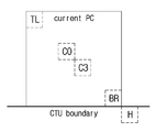
- the spatial neighboring candidate can be derived using the sample adjacent to the CTU boundary.
- the sample adjacent to the CTU boundary may represent a sample included in the CTU different from the current block, or may represent a sample included in the same CTU as the current block.
- FIG. 12 is an illustration showing an example in which a spatial non-neighbor sample that is not adjacent to the same CTU as the current block is replaced with a sample adjacent to the CTU.
- the spatial non-neighbor sample is not included in the same CTU as the current block, at least one of the samples adjacent to the CTU may be used to derive a merge candidate of the current block. If the spatial non-neighbor sample is located at the upper end of the current block (i.e., the y-coordinate of the spatial neighboring block is smaller than the y-coordinate of the upper left sample of the current block) A sample located on the same vertical line as that of FIG. Alternatively, a sample may be used which is obtained by adding or subtracting an offset to the x coordinate of the spatial non-neighbor sample among the samples adjacent to the CTU.
- the spatial non-neighbor sample is located on the left side of the current block (i.e., the x-coordinate of the spatial neighbor sample is smaller than the x-coordinate of the upper left sample of the current block)
- Samples located on the same horizontal line may be used.
- a sample may be used in which the offset is added to or subtracted from the y coordinate of the spatial non-neighbor sample among the samples adjacent to the CTU.
- the merge candidate of the current block may be derived using the located sample.
- the search for the merge candidate may be performed in the order of a spatial neighbor block and a spatial non-neighbor block.
- a block that is not adjacent to the current block can be used as a merge candidate of the current block.
- the motion information of the spatial merge candidate may be set to be the same as the motion information of the spatial neighboring block / spatial non-neighboring block.
- Spatial merge candidates can be determined by searching for neighboring blocks in a predetermined order. For example, in the example shown in FIG. 10, a search for spatial merge candidate determination can be performed in the order of A 1 , B 1 , B 0 , A 0 and B 2 blocks. At this time, the B 2 block can be used when at least one of the remaining blocks (i.e., A 1 , B 1 , B 0, and A 0 ) is not present or at least one is coded in the intra prediction mode.
- the search order of the spatial merge candidate may be as previously defined in the encoder / decoder. Alternatively, the search order of the spatial merge candidate may be determined adaptively according to the size or type of the current block. Alternatively, the search order of the spatial merge candidate may be determined based on the information signaled through the bit stream.
- the temporal merge candidate may be derived from the temporally neighboring block of the current block (S920).
- the temporal neighbor block may refer to a co-located block included in the collocated picture.
- a collocated picture has a picture order count (POC) different from the current picture including the current block.
- the collocated picture can be determined as a picture having a predefined index in the reference picture list or a picture having the smallest output order (POC) difference from the current picture.
- the collocated picture may be determined by the information signaled from the bitstream.
- the temporal merge candidate motion information can be determined based on the motion information of the collocated block.
- the temporal merge candidate motion vector may be determined based on the motion vector of the collocated block.
- the temporal merge candidate motion vector may be set equal to the motion vector of the collocated block.
- the temporal merge candidate motion vector may be based on the difference in the output order (POC) between the current picture and the reference picture of the current block and / or the output order (POC) difference between the reference picture of the collocated picture and the collocated picture. And then scaling the motion vector of the collocated block.
- POC output order
- both the motion vector of the collocated block and the motion vector scaled by the collocated block may be used as a motion vector of the temporal merging candidate.
- a motion vector of a collocated block may be set as a motion vector of a first temporal merge candidate, and a value obtained by scaling a motion vector of the collocated block may be set as a motion vector of a second temporal merge candidate.
- the collocated block may be determined to be any block in the block having the same position and size as the current block in the collocated picture or a block adjacent to the block having the same position and size as the current block.
- FIG. 14 is a diagram showing the positions of candidate blocks that can be used as a collocated block.
- a block including the position of a neighboring block adjacent to a predetermined boundary of the current block in the collocated picture may be selected as a collocated block.
- the reference picture index of the merge candidate having the higher priority (or lower) can be set as the reference picture index of the average merge candidate by setting the priority. For example, when the first merging candidate is bidirectionally predicted and the second merging candidate is one-directionally predicted, the reference picture index of the first merging candidate to which bidirectional prediction is applied can be determined as the reference picture index of the average merging candidate.
- the motion vector candidate specified by the information is set as the motion vector prediction value of the current block, the motion vector difference value is added to the motion vector prediction value, and the motion vector of the current block is obtained. At this time, the motion vector difference value can be parsed through the bit stream.
- At least one of the spatial merge candidates A0, A1, A2, A3 and A4 derived based on the quad tree unit upper node block can be used for block 0 and block 1 of the non-circular form divided into the binary tree form. Accordingly, block 0 and block 1 can use the same spatial merge candidate.
- the merge inducing area may be a square shape or a non-square shape.
- a square or non-square prediction unit or coding unit may be defined as a merge induction area.
- the merge inducing area of the non-circular shape may be limited to a predetermined shape.
- the non-tetragonal merge inducing region may take the form of 2NxN or Nx2N.
- the spatial non-neighboring block selected in the previously encoded / decoded block may be determined as not available as a merge candidate of the current block.
- Examples of computer-readable recording media include magnetic media such as hard disks, floppy disks and magnetic tape, optical recording media such as CD-ROMs and DVDs, magneto-optical media such as floptical disks, media, and hardware devices specifically configured to store and execute program instructions such as ROM, RAM, flash memory, and the like.
- the hardware device may be configured to operate as one or more software modules for performing the processing according to the present invention, and vice versa.
Landscapes
- Engineering & Computer Science (AREA)
- Multimedia (AREA)
- Signal Processing (AREA)
- Compression Or Coding Systems Of Tv Signals (AREA)
Abstract
Priority Applications (13)
| Application Number | Priority Date | Filing Date | Title |
|---|---|---|---|
| CN202310880322.9A CN116866573A (zh) | 2017-10-20 | 2018-10-19 | 视频信号处理方法及装置 |
| CN202310875543.7A CN116866571A (zh) | 2017-10-20 | 2018-10-19 | 视频信号处理方法及装置 |
| AU2018351405A AU2018351405B2 (en) | 2017-10-20 | 2018-10-19 | Video signal processing method and device |
| CN201880035880.2A CN110710210B (zh) | 2017-10-20 | 2018-10-19 | 视频信号处理方法及装置 |
| CN202310876424.3A CN116866592A (zh) | 2017-10-20 | 2018-10-19 | 视频信号处理方法以及存储介质 |
| CN202310878146.5A CN116866572A (zh) | 2017-10-20 | 2018-10-19 | 视频信号处理方法及装置 |
| CA3067528A CA3067528A1 (fr) | 2017-10-20 | 2018-10-19 | Procede et dispositif de traitement de signal video |
| CN202310876358.XA CN116866590A (zh) | 2017-10-20 | 2018-10-19 | 视频信号处理方法及装置 |
| CN202310876166.9A CN116916042A (zh) | 2017-10-20 | 2018-10-19 | 视频信号处理方法以及存储介质 |
| US16/622,434 US11025943B2 (en) | 2017-10-20 | 2018-10-19 | Video signal processing method and device |
| US17/246,525 US11627330B2 (en) | 2017-10-20 | 2021-04-30 | Video signal processing method and device |
| US18/117,625 US12231672B2 (en) | 2017-10-20 | 2023-03-06 | Video signal processing method and device |
| US19/021,085 US20250159230A1 (en) | 2017-10-20 | 2025-01-14 | Video signal processing method and device |
Applications Claiming Priority (2)
| Application Number | Priority Date | Filing Date | Title |
|---|---|---|---|
| KR10-2017-0136512 | 2017-10-20 | ||
| KR20170136512 | 2017-10-20 |
Related Child Applications (2)
| Application Number | Title | Priority Date | Filing Date |
|---|---|---|---|
| US16/622,434 A-371-Of-International US11025943B2 (en) | 2017-10-20 | 2018-10-19 | Video signal processing method and device |
| US17/246,525 Division US11627330B2 (en) | 2017-10-20 | 2021-04-30 | Video signal processing method and device |
Publications (1)
| Publication Number | Publication Date |
|---|---|
| WO2019078664A1 true WO2019078664A1 (fr) | 2019-04-25 |
Family
ID=66174112
Family Applications (1)
| Application Number | Title | Priority Date | Filing Date |
|---|---|---|---|
| PCT/KR2018/012393 Ceased WO2019078664A1 (fr) | 2017-10-20 | 2018-10-19 | Procédé et dispositif de traitement de signal vidéo |
Country Status (6)
| Country | Link |
|---|---|
| US (4) | US11025943B2 (fr) |
| KR (1) | KR102822983B1 (fr) |
| CN (7) | CN110710210B (fr) |
| AU (1) | AU2018351405B2 (fr) |
| CA (2) | CA3293037A1 (fr) |
| WO (1) | WO2019078664A1 (fr) |
Families Citing this family (16)
| Publication number | Priority date | Publication date | Assignee | Title |
|---|---|---|---|---|
| CA3092638A1 (fr) * | 2018-03-01 | 2019-09-06 | Arris Enterprises Llc | Systeme et procede de stockage d'informations de mouvement pour codage video et signalisation |
| CN120128726A (zh) | 2018-05-23 | 2025-06-10 | 株式会社Kt | 对视频进行解码、编码的方法以及用于传送压缩视频数据的装置 |
| WO2019231206A1 (fr) | 2018-05-30 | 2019-12-05 | 디지털인사이트주식회사 | Procédé et dispositif de codage/décodage d'image |
| WO2020054784A1 (fr) * | 2018-09-11 | 2020-03-19 | パナソニック インテレクチュアル プロパティ コーポレーション オブ アメリカ | Dispositif de codage, dispositif de décodage, procédé de codage et procédé de décodage |
| WO2020103935A1 (fr) * | 2018-11-22 | 2020-05-28 | Beijing Bytedance Network Technology Co., Ltd. | Procédé de mélange pour une inter-prédiction avec partition géométrique |
| KR20240024335A (ko) | 2018-11-22 | 2024-02-23 | 베이징 바이트댄스 네트워크 테크놀로지 컴퍼니, 리미티드 | 서브 블록 기반 인터 예측을 위한 조정 방법 |
| WO2020116242A1 (fr) * | 2018-12-07 | 2020-06-11 | パナソニック インテレクチュアル プロパティ コーポレーション オブ アメリカ | Dispositif de codage, dispositif de décodage, procédé de codage et procédé de décodage |
| US10904557B2 (en) * | 2019-01-22 | 2021-01-26 | Tencent America LLC | Method and apparatus for video coding |
| CN113574890B (zh) * | 2019-03-11 | 2024-04-12 | 北京字节跳动网络技术有限公司 | 基于指定的候选的成对运动候选列的构造 |
| JP2022533295A (ja) * | 2019-03-13 | 2022-07-22 | エスゼット ディージェイアイ テクノロジー カンパニー リミテッド | 動画処理方法、装置、及びコンピュータプログラム |
| WO2020263067A1 (fr) * | 2019-06-26 | 2020-12-30 | 삼성전자주식회사 | Procédé de codage vidéo pour effectuer une prédiction basée sur un modèle affine compte tenu d'un ordre de codage, dispositif associé et procédé de décodage vidéo permettant de réaliser une prédiction basée sur un modèle affine compte tenu de l'ordre de décodage, et dispositif associé |
| KR102808776B1 (ko) | 2019-08-13 | 2025-05-15 | 두인 비전 컴퍼니 리미티드 | 서브 블록 기반 인터 예측의 모션 정밀도 |
| WO2021052505A1 (fr) | 2019-09-22 | 2021-03-25 | Beijing Bytedance Network Technology Co., Ltd. | Rééchantillonnage d'image de référence dans un traitement vidéo |
| WO2023158766A1 (fr) * | 2022-02-16 | 2023-08-24 | Beijing Dajia Internet Information Technology Co., Ltd. | Procédés et dispositifs de dérivation de candidats pour un mode de fusion affine en codage vidéo |
| US20250267278A1 (en) * | 2022-04-29 | 2025-08-21 | Mediatek Inc. | Efficient geometric partitioning mode video coding |
| WO2024012045A1 (fr) * | 2022-07-14 | 2024-01-18 | Mediatek Inc. | Procédés et appareil de codage vidéo utilisant des tables de prédiction de vecteur de mouvement basées sur l'historique et basées sur une ctu |
Citations (5)
| Publication number | Priority date | Publication date | Assignee | Title |
|---|---|---|---|---|
| US20120320984A1 (en) * | 2011-06-14 | 2012-12-20 | Minhua Zhou | Inter-Prediction Candidate Index Coding Independent of Inter-Prediction Candidate List Construction in Video Coding |
| US20130077691A1 (en) * | 2011-06-20 | 2013-03-28 | Qualcomm Incorporated | Parallelization friendly merge candidates for video coding |
| KR20130135368A (ko) * | 2011-06-24 | 2013-12-10 | 미디어텍 인크. | 모션 벡터 예측기에서의 중복성을 제거하는 방법 및 장치 |
| KR20140026429A (ko) * | 2011-05-27 | 2014-03-05 | 파나소닉 주식회사 | 화상 부호화 방법, 화상 부호화 장치, 화상 복호 방법, 화상 복호 장치, 및, 화상 부호화 복호 장치 |
| KR20160085237A (ko) * | 2012-11-27 | 2016-07-15 | 경희대학교 산학협력단 | 머지를 기반으로 한 복호화 방법 및 장치 |
Family Cites Families (26)
| Publication number | Priority date | Publication date | Assignee | Title |
|---|---|---|---|---|
| EP2664146A1 (fr) * | 2011-01-14 | 2013-11-20 | Motorola Mobility LLC | Mode de fusion spatiale et temporelle conjointe de blocs pour hevc |
| US8929450B2 (en) * | 2011-01-14 | 2015-01-06 | Google Technology Holdings LLC | Temporal block merge mode |
| US9143795B2 (en) | 2011-04-11 | 2015-09-22 | Texas Instruments Incorporated | Parallel motion estimation in video coding |
| US20140078254A1 (en) | 2011-06-15 | 2014-03-20 | Mediatek Inc. | Method and Apparatus of Motion and Disparity Vector Prediction and Compensation for 3D Video Coding |
| MY181718A (en) | 2011-06-30 | 2021-01-05 | Sun Patent Trust | Image decoding method, image encoding method, image decoding device, image encoding device, and image encoding/decoding device |
| HRP20260268T1 (hr) | 2011-09-09 | 2026-04-10 | Lg Electronics Inc. | Uređaj za dekodiranje slike, uređaj za kodiranje slike i uređaj za prijenos podataka za sliku |
| CN103858428B (zh) * | 2011-10-19 | 2018-07-03 | 太阳专利托管公司 | 图像编码方法、图像编码装置、图像解码方法及图像解码装置 |
| US9571833B2 (en) * | 2011-11-04 | 2017-02-14 | Nokia Technologies Oy | Method for coding and an apparatus |
| CN110198449B (zh) * | 2011-11-08 | 2022-01-04 | 韩国电子通信研究院 | 用于共享候选者列表的方法和装置 |
| EP2942961A1 (fr) * | 2011-11-23 | 2015-11-11 | HUMAX Holdings Co., Ltd. | Procédés de codage/décodage de vidéo au moyen de l'ensemble commun de candidats de fusion des partitions asymétriques |
| WO2013094960A1 (fr) * | 2011-12-23 | 2013-06-27 | 한국전자통신연구원 | Procédé et appareil pour la définition d'un indice d'image de référence d'un candidat à la fusion temporelle |
| WO2013099285A1 (fr) | 2011-12-28 | 2013-07-04 | 株式会社Jvcケンウッド | Dispositif de codage vidéo, procédé de codage vidéo et programme de codage vidéo, et dispositif de décodage vidéo, procédé de décodage vidéo et programme de décodage vidéo |
| US20130177083A1 (en) * | 2012-01-05 | 2013-07-11 | Qualcomm Incorporated | Motion vector candidate index signaling in video coding |
| US20130188716A1 (en) * | 2012-01-20 | 2013-07-25 | Qualcomm Incorporated | Temporal motion vector predictor candidate |
| US9729873B2 (en) * | 2012-01-24 | 2017-08-08 | Qualcomm Incorporated | Video coding using parallel motion estimation |
| US9338451B2 (en) * | 2012-04-12 | 2016-05-10 | Qualcomm Incorporated | Common spatial candidate blocks for parallel motion estimation |
| JP6422011B2 (ja) * | 2012-05-11 | 2018-11-14 | サン パテント トラスト | 動画像符号化方法、動画像復号化方法、動画像符号化装置および動画像復号化装置 |
| CN110545419B (zh) | 2012-10-12 | 2022-11-22 | 韩国电子通信研究院 | 图像编码/解码方法和使用其的装置 |
| JP6441236B2 (ja) * | 2013-12-19 | 2018-12-19 | シャープ株式会社 | 画像復号装置及び画像符号化装置 |
| US10027981B2 (en) | 2014-09-01 | 2018-07-17 | Hfi Innovation Inc. | Method of intra picture block copy for screen content and video coding |
| US10560718B2 (en) * | 2016-05-13 | 2020-02-11 | Qualcomm Incorporated | Merge candidates for motion vector prediction for video coding |
| CN109479141B (zh) * | 2016-07-12 | 2023-07-14 | 韩国电子通信研究院 | 图像编码/解码方法和用于所述方法的记录介质 |
| CN116567226A (zh) * | 2016-08-11 | 2023-08-08 | Lx 半导体科技有限公司 | 图像编码/解码设备和图像数据的发送设备 |
| US10750190B2 (en) * | 2016-10-11 | 2020-08-18 | Lg Electronics Inc. | Video decoding method and device in video coding system |
| US20180242024A1 (en) * | 2017-02-21 | 2018-08-23 | Mediatek Inc. | Methods and Apparatuses of Candidate Set Determination for Quad-tree Plus Binary-tree Splitting Blocks |
| EP3895419A4 (fr) * | 2018-12-13 | 2022-05-04 | Tencent America LLC | Décodage vidéo par détermination d'une reconstruction de bloc sur la base d'informations de signalisation |
-
2018
- 2018-10-19 CN CN201880035880.2A patent/CN110710210B/zh active Active
- 2018-10-19 CA CA3293037A patent/CA3293037A1/en active Pending
- 2018-10-19 KR KR1020180125017A patent/KR102822983B1/ko active Active
- 2018-10-19 CN CN202310876166.9A patent/CN116916042A/zh active Pending
- 2018-10-19 WO PCT/KR2018/012393 patent/WO2019078664A1/fr not_active Ceased
- 2018-10-19 US US16/622,434 patent/US11025943B2/en active Active
- 2018-10-19 CN CN202310878146.5A patent/CN116866572A/zh active Pending
- 2018-10-19 CN CN202310880322.9A patent/CN116866573A/zh active Pending
- 2018-10-19 AU AU2018351405A patent/AU2018351405B2/en active Active
- 2018-10-19 CN CN202310876358.XA patent/CN116866590A/zh active Pending
- 2018-10-19 CA CA3067528A patent/CA3067528A1/fr active Pending
- 2018-10-19 CN CN202310875543.7A patent/CN116866571A/zh active Pending
- 2018-10-19 CN CN202310876424.3A patent/CN116866592A/zh active Pending
-
2021
- 2021-04-30 US US17/246,525 patent/US11627330B2/en active Active
-
2023
- 2023-03-06 US US18/117,625 patent/US12231672B2/en active Active
-
2025
- 2025-01-14 US US19/021,085 patent/US20250159230A1/en active Pending
Patent Citations (5)
| Publication number | Priority date | Publication date | Assignee | Title |
|---|---|---|---|---|
| KR20140026429A (ko) * | 2011-05-27 | 2014-03-05 | 파나소닉 주식회사 | 화상 부호화 방법, 화상 부호화 장치, 화상 복호 방법, 화상 복호 장치, 및, 화상 부호화 복호 장치 |
| US20120320984A1 (en) * | 2011-06-14 | 2012-12-20 | Minhua Zhou | Inter-Prediction Candidate Index Coding Independent of Inter-Prediction Candidate List Construction in Video Coding |
| US20130077691A1 (en) * | 2011-06-20 | 2013-03-28 | Qualcomm Incorporated | Parallelization friendly merge candidates for video coding |
| KR20130135368A (ko) * | 2011-06-24 | 2013-12-10 | 미디어텍 인크. | 모션 벡터 예측기에서의 중복성을 제거하는 방법 및 장치 |
| KR20160085237A (ko) * | 2012-11-27 | 2016-07-15 | 경희대학교 산학협력단 | 머지를 기반으로 한 복호화 방법 및 장치 |
Also Published As
| Publication number | Publication date |
|---|---|
| US20250159230A1 (en) | 2025-05-15 |
| US11025943B2 (en) | 2021-06-01 |
| US12231672B2 (en) | 2025-02-18 |
| CN116866573A (zh) | 2023-10-10 |
| US20230209080A1 (en) | 2023-06-29 |
| KR102822983B1 (ko) | 2025-06-24 |
| AU2018351405A1 (en) | 2020-01-16 |
| CN116866571A (zh) | 2023-10-10 |
| US20200112738A1 (en) | 2020-04-09 |
| CA3293037A1 (en) | 2026-03-02 |
| CN110710210A (zh) | 2020-01-17 |
| US20210258600A1 (en) | 2021-08-19 |
| US11627330B2 (en) | 2023-04-11 |
| AU2018351405B2 (en) | 2023-06-08 |
| CA3067528A1 (fr) | 2019-04-25 |
| CN116866592A (zh) | 2023-10-10 |
| CN116866590A (zh) | 2023-10-10 |
| CN116866572A (zh) | 2023-10-10 |
| CN110710210B (zh) | 2023-08-04 |
| CN116916042A (zh) | 2023-10-20 |
| KR20190044533A (ko) | 2019-04-30 |
Similar Documents
| Publication | Publication Date | Title |
|---|---|---|
| WO2019078664A1 (fr) | Procédé et dispositif de traitement de signal vidéo | |
| WO2018066959A1 (fr) | Procédé et appareil de traitement de signal vidéo | |
| WO2018212578A1 (fr) | Procédé et dispositif de traitement de signal vidéo | |
| WO2019045392A1 (fr) | Procédé et dispositif destiné au traitement des signaux vidéo | |
| WO2018117546A1 (fr) | Procédé et dispositif de traitement de signal vidéo | |
| WO2018212577A1 (fr) | Procédé et dispositif de traitement de signal vidéo | |
| WO2018008904A2 (fr) | Procédé et appareil de traitement de signal vidéo | |
| WO2018044088A1 (fr) | Procédé et dispositif de traitement d'un signal vidéo | |
| WO2018088805A1 (fr) | Procédé et appareil de traitement de signal vidéo | |
| WO2018026222A1 (fr) | Procédé et dispositif de traitement de signal vidéo | |
| WO2018044087A1 (fr) | Procédé et dispositif de traitement de signal vidéo | |
| WO2019078581A1 (fr) | Procédé, dispositif et support d'enregistrement stockant un train de bits, pour le codage/décodage d'image | |
| WO2018008906A1 (fr) | Procédé et appareil de traitement de signal vidéo | |
| WO2018008905A1 (fr) | Procédé et appareil de traitement de signal vidéo | |
| WO2018106047A1 (fr) | Procédé et appareil de traitement de signal vidéo | |
| WO2017188652A1 (fr) | Procédé et dispositif destinés au codage/décodage d'image | |
| WO2017039256A1 (fr) | Procédé et dispositif de traitement de signal vidéo | |
| WO2018056703A1 (fr) | Procédé et appareil de traitement de signal vidéo | |
| WO2018044089A1 (fr) | Procédé et dispositif pour traiter un signal vidéo | |
| WO2018056702A1 (fr) | Procédé et appareil de traitement de signal vidéo | |
| WO2013154366A1 (fr) | Procédé de transformation faisant appel à des informations de bloc, et appareil utilisant ce procédé | |
| WO2012124961A2 (fr) | Procédé et appareil d'encodage d'images et procédé et appareil de décodage d'images | |
| WO2019235891A1 (fr) | Procédé et appareil de traitement de signal vidéo | |
| WO2018066958A1 (fr) | Procédé et appareil de traitement de signal vidéo | |
| WO2016085231A1 (fr) | Procédé et dispositif de traitement de signal vidéo |
Legal Events
| Date | Code | Title | Description |
|---|---|---|---|
| 121 | Ep: the epo has been informed by wipo that ep was designated in this application |
Ref document number: 18868691 Country of ref document: EP Kind code of ref document: A1 |
|
| ENP | Entry into the national phase |
Ref document number: 3067528 Country of ref document: CA |
|
| ENP | Entry into the national phase |
Ref document number: 2018351405 Country of ref document: AU Date of ref document: 20181019 Kind code of ref document: A |
|
| NENP | Non-entry into the national phase |
Ref country code: DE |
|
| 122 | Ep: pct application non-entry in european phase |
Ref document number: 18868691 Country of ref document: EP Kind code of ref document: A1 |
|
| 32PN | Ep: public notification in the ep bulletin as address of the adressee cannot be established |
Free format text: NOTING OF LOSS OF RIGHTS PURSUANT TO RULE 112(1) EPC (EPO FORM 1205A DATED 22/01/2021) |
|
| 122 | Ep: pct application non-entry in european phase |
Ref document number: 18868691 Country of ref document: EP Kind code of ref document: A1 |