WO2019082305A1 - コンバイン - Google Patents
コンバインInfo
- Publication number
- WO2019082305A1 WO2019082305A1 PCT/JP2017/038544 JP2017038544W WO2019082305A1 WO 2019082305 A1 WO2019082305 A1 WO 2019082305A1 JP 2017038544 W JP2017038544 W JP 2017038544W WO 2019082305 A1 WO2019082305 A1 WO 2019082305A1
- Authority
- WO
- WIPO (PCT)
- Prior art keywords
- threshing
- frame
- supported
- engine
- main frames
- Prior art date
- Legal status (The legal status is an assumption and is not a legal conclusion. Google has not performed a legal analysis and makes no representation as to the accuracy of the status listed.)
- Ceased
Links
Images





Classifications
-
- A—HUMAN NECESSITIES
- A01—AGRICULTURE; FORESTRY; ANIMAL HUSBANDRY; HUNTING; TRAPPING; FISHING
- A01F—PROCESSING OF HARVESTED PRODUCE; HAY OR STRAW PRESSES; DEVICES FOR STORING AGRICULTURAL OR HORTICULTURAL PRODUCE
- A01F12/00—Parts or details of threshing apparatus
- A01F12/18—Threshing devices
- A01F12/181—Adjustable threshing mechanisms
-
- A—HUMAN NECESSITIES
- A01—AGRICULTURE; FORESTRY; ANIMAL HUSBANDRY; HUNTING; TRAPPING; FISHING
- A01D—HARVESTING; MOWING
- A01D67/00—Undercarriages or frames specially adapted for harvesters or mowers; Mechanisms for adjusting the frame; Platforms
-
- A—HUMAN NECESSITIES
- A01—AGRICULTURE; FORESTRY; ANIMAL HUSBANDRY; HUNTING; TRAPPING; FISHING
- A01D—HARVESTING; MOWING
- A01D69/00—Driving mechanisms or parts thereof for harvesters or mowers
-
- A—HUMAN NECESSITIES
- A01—AGRICULTURE; FORESTRY; ANIMAL HUSBANDRY; HUNTING; TRAPPING; FISHING
- A01F—PROCESSING OF HARVESTED PRODUCE; HAY OR STRAW PRESSES; DEVICES FOR STORING AGRICULTURAL OR HORTICULTURAL PRODUCE
- A01F12/00—Parts or details of threshing apparatus
- A01F12/60—Grain tanks
-
- A—HUMAN NECESSITIES
- A01—AGRICULTURE; FORESTRY; ANIMAL HUSBANDRY; HUNTING; TRAPPING; FISHING
- A01F—PROCESSING OF HARVESTED PRODUCE; HAY OR STRAW PRESSES; DEVICES FOR STORING AGRICULTURAL OR HORTICULTURAL PRODUCE
- A01F12/00—Parts or details of threshing apparatus
Definitions
- the present invention relates to a combine that is configured to harvest cropped rice straw while traveling and to thresh the harvested crop straw with a threshing device.
- the threshing apparatus is provided with a threshing part that performs a threshing process and a sorting part that sorts the processed material after the threshing process by the threshing part is vertically aligned.
- the threshing part and the sorting part were integrally stored in the case formed in a substantially box shape, and the whole threshing device was mounted and supported by the main frame provided at the lower part of the vehicle body ( For example, refer to Patent Document 1).
- the threshing device when attempting to increase the capacity of the threshing device, the threshing device becomes tall in the vertical direction. As a result, the vertical height of the vehicle becomes large, the center of gravity position becomes high, and there is a disadvantage that the running stability is deteriorated.
- the characteristic configuration of the combine according to the present invention is The left and right main frames extending in the longitudinal direction of the airframe and the threshing device disposed between the left and right main frames are provided.
- the threshing apparatus is provided with a threshing part that performs grain shedding processing, and a sorting part that is provided below the threshing part and that sorts the treated material after the grain shedding processing has been performed by the threshing part.
- a threshing frame constituting the threshing portion is mounted and supported on the left and right main frames,
- a sorting unit frame constituting the sorting unit is suspended and supported by the main frames on the left and right.
- the threshing part and the sorting part are separately configured by separate frames of the threshing frame and the sorting part frame.
- a threshing frame is located in the upper side of the main frame on either side, and is mounted and supported by the main frame on either side.
- the sorting unit frame is located below the left and right main frames, and is suspended and supported by the left and right main frames.
- the threshing part and the sorting part are separately formed, when the threshing apparatus is assembled to the machine, the threshing part and the sorting part can be separately attached to the main frame respectively, so that the whole threshing apparatus can be completed in one shot. Since the outer shape of the device to be assembled is smaller and the weight thereof is smaller as compared with the case of attaching to the case, the assembling operation is easy.
- the sorting unit frame is located below the main frame and is suspended and supported, so the whole threshing device is in a state of being lowered downward with respect to the main frame. As a result, even if the threshing device becomes large and the threshing device itself becomes tall in the vertical direction, the sorting unit is located below the main frame, so that the overall height of the fuselage can be prevented from increasing. it can.
- Running parts are provided on the left and right sides of the machine, An axle of the traveling unit is provided at a position lower than the left and right main frames, The left and right traveling parts are provided in a state located on the outer side in the left-right direction of the machine than the left and right main frames, The left and right main frames are preferably supported by the left and right traveling parts.
- the left and right traveling parts have the axle at a lower position than the left and right main frames, and are located outward in the left and right direction of the fuselage of the main frame.
- the entire airframe can be stably supported at a large distance and at a position lower than the main frame.
- a traveling part connecting body for connecting the left and right traveling parts is provided.
- the rigidity of the support structure of the left and right traveling parts becomes large and can be firmly supported.
- a fuel tank support frame is provided, which connects the left and right sides of the lower portion of the sorting unit frame and projects outward of the main frame in the left and right direction more than the main frame of the left and right sides of the main frame. , It is preferable that the fuel tank be mounted and supported on the fuel tank support frame.
- the tank support frame is provided in a state in which the left and right side portions of the lower portion of the sorting unit frame are connected to extend in the left-right direction.
- the tank support frame protrudes outward on one side in the left-right direction of the machine than the main frame, and the fuel tank is mounted and supported at the protruding portion.
- the fuel tank supporting frame is stably and firmly supported by effectively utilizing the separating portion frame having a large rigidity to constitute the separating portion, and the one side outward side of the main frame in the lateral direction of the vehicle body
- the fuel tank can be supported without interfering with the main frame.
- An operating unit is provided in front of the threshing unit, Left and right vertically oriented frame bodies are provided on the left and right sides of the front end of the threshing frame, An operating unit frame is provided so as to project forward from the left and right vertical frame bodies toward the airframe, It is preferable that the driving unit be mounted on and supported by the driving unit frame.
- the cabin frame is provided in a state of projecting forward from the left and right vertical frame bodies in the threshing frame, and the cabin is mounted and supported on the cabin frame. Therefore, for example, the cabin can be supported by effectively utilizing the threshing frame having a large rigidity to form the threshing portion without extending a long support member or the like from the main frame.
- a reaper transport unit for harvesting cropped cereals and transporting the harvested cereals to the threshing device
- Left and right vertically oriented frame bodies are provided on the left and right sides of the front end of the threshing frame, Among the main frames on the left and right, the base end of the reaper transport unit is supported over the upper surface of the front projection projecting forward from the left and right vertical frame bodies and the front surface of the vertical frame bodies. Is preferred.
- the base end portion of the reaper transport unit is supported by utilizing the corner portion formed by the forward protrusion projecting forward from the left and right main frames and the vertically oriented frame body in the threshing frame There is.
- the configuration of the threshing frame can be used to support the base end of the reaper transport unit, and stably supported without causing complication of the structure such as providing a special pivot point portion separately be able to.
- Running parts are provided on the left and right sides of the machine,
- the left and right traveling units are provided with a front traveling device and a rear traveling device.
- front portions of the left and right main frames are supported by the front traveling device, and rear portions of the left and right main frames are supported by the rear traveling device.
- the front side traveling devices on the left and right sides support the front side of the vehicle body via the left and right main frames
- the rear traveling devices on the left and right sides support the rear side of the vehicle body via the main frames on the left and right. Therefore, the entire vehicle body is stably supported by the four traveling devices respectively located on the front and rear sides on the left and right.
- a front connecting portion connecting the front of the left and right main frames and a rear connecting portion connecting the rear of the left and right main frames are provided.
- the front side is connected by the front side connection part, and the rear side is connected by the rear side connection part. Therefore, since it connects in a rectangular frame shape, the whole rigidity can be raised and the whole body can be supported firmly.
- the front side connecting portion is provided on the front side of the sorting portion, and the rear side connecting portion is provided on the rear side of the sorting portion.
- the front side coupling portion and the rear side coupling portion can favorably couple the left and right main frames at an appropriate position which does not interfere with the sorting portion.
- the front end portion of the sorting unit frame and the front connection portion be connected.
- the rigidity of the airframe support structure can be further enhanced.
- a base portion provided at the front of the left and right main frames, an upper horizontal frame connecting the left and right base portions, and a lower side than the left and right base portions. It is preferable that a lower horizontal frame connecting the left and right base portions be provided, and lower portions of the left and right base portions be supported by the left and right front traveling devices.
- the left and right side portions are connected by the upper horizontal frame and the lower horizontal frame, so that the left and right main frames can be firmly connected at the upper and lower sides. And since the lower part of the front projection part is supported by the front side traveling device, processing labor is reduced compared with the structure which directly supports the main frame which is a large-sized member by the front side traveling device.
- a reaper transport unit for harvesting cropped cereals and transporting the harvested cereals to the threshing device
- the lower horizontal frame is connected to the left and right sides of the front end of the sorting unit frame and is connected to the left and right front-to-back connecting members extending forward and backward along the front-rear direction and the rear portions of the left and right front-to-back connecting members And a front side connection member connecting front portions of the left and right front and rear connection members, It is preferable that an actuator capable of lifting and lowering the reaper transport unit is supported by the front side horizontal coupling body.
- the lower horizontal frame is formed in a substantially rectangular frame shape by mutually connecting the left and right front-to-rear connection body, the rear side-side connection body, and the front side horizontal connection body, rigidity can be enhanced.
- the sorting unit frame which is the main frame member.
- a transmission case in which a transmission mechanism for traveling drive be installed be provided in a state in which it is inserted between the upper lateral frame and the lower lateral frame.
- Left and right sides of the transmission case are provided with axle cases of the left and right front traveling devices, and left and right relay transmission cases connecting the transmission case and the left and right axle cases,
- the left and right axle cases are preferably connected to the left and right front projections and are connected to the lower horizontal frame.
- the power from the transmission case is transmitted to the left and right front traveling devices via the transmission shafts in the left and right axle cases and the transmission mechanism in the left and right relay transmission cases.
- the left and right axle cases are rigidly supported by the main frame via the front projection in a state in which the lower lateral frame is connected to increase the rigidity.
- the rear connection portion includes a rear connection body located below the left and right main frames and extending across the left and right main frames. It is preferable that a traveling device support provided over the left and right rear side traveling devices be swingably supported by the rear connection body around a longitudinal axis.
- the traveling device support can be supported by the rear connection body extended and firmly supported over the left and right main frames. Since the traveling device support that supports the left and right rear traveling devices is swingably supported by the rear connection body about the longitudinal axis, the left and right rear traveling devices follow the unevenness of the ground while moving left and right. It can be operated rolling.
- a grain tank for storing grains that have been subjected to grain shedding processing by the threshing device, and an engine as a power source The grain tank and the engine are arranged in the front-rear direction, with the grain tank located on the front side of the machine above the threshing device and the engine located on the rear side of the machine. It is preferable that the grain tank and the engine are supported by left and right vertically oriented support portions provided upright from the left and right main frames in a state of being provided wide along the longitudinal direction of the machine body.
- the grain tank and the engine are deployed using the area above the threshing device, for example, even if the threshing device becomes large in order to enhance the capacity of the threshing device,
- the engine can be rationally deployed without increasing the width dimension of the airframe as compared with the case where the engine is provided on the side of the threshing apparatus or the engine is provided on the side of the grain tank.
- the grain tank and the engine can be stably supported by the left and right vertical support portions provided over a wide range in the longitudinal direction of the airframe.
- a threshing upper connection body connecting upper portions of the left and right vertical support portions is provided, and the threshing upper connection body is connected to a top plate of the threshing device.
- the upper portions of the left and right vertical supports, the threshing upper connection body, and the top plate of the threshing device are connected to each other, and the lower portions of the left and right vertical supports are the left and right main frames. Because they are connected to each other, they can form a rigid support structure having high rigidity in a framework state.
- a grain tank support frame for supporting the grain tank, and an engine support frame for supporting the engine Preferably, the grain tank support frame and the engine support frame extend over the left and right vertical supports and are supported by the left and right vertical supports.
- the grain tank is stably supported by the grain tank support frame, and the engine is stably supported by the engine support frame. Also, since the grain tank support frame and the engine support frame are supported by the left and right vertical supports, respectively, the grain tank support frame and the engine support frame are used to form a rigid support structure having high rigidity. can do.
- An engine as a power source, a radiator for cooling the engine, and an exhaust treatment device for treating exhaust gas from the engine are provided above the threshing device.
- the exhaust treatment device and the radiator are separately disposed on the left and right sides with respect to the engine in the longitudinal direction of the vehicle body, and the radiator is laterally outward one side than the lateral end of the threshing device.
- the radiator is supported by the threshing device.
- the exhaust treatment device and the radiator do not protrude upward with respect to the engine, and the engine, the exhaust treatment device, and the radiator can be disposed in a state of being compacted in the vertical direction. .
- the exhaust treatment device treats high temperature exhaust gas, it is supported by an engine.
- the radiator is supported by the threshing device because it is only connected with the engine in the cooling water circulation path and does not become as hot as the exhaust gas flow point.
- the exhaust treatment device and the radiator can be properly deployed at a position close to the engine.
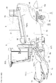
- the combine harvester threshs the crop cut by the reaper transport unit 1 for cutting the crop and transports it backward, the operation unit 3 covered with the cabin 2, and the reaper transport unit 1
- Threshing device 4 for performing the process
- a grain tank 5 for storing grains obtained by threshing with the threshing device 4
- a driving unit 6 having an engine 21 as a power source
- left and right traveling located on both sides of the machine Part 7
- the left and right traveling units 7 respectively have a front wheel 8 as a front traveling device that can not be steered and is rotationally driven, and a rear wheel 9 as a rear traveling device that can be steered.
- the longitudinal direction of the aircraft when defining the longitudinal direction of the aircraft, it is defined along the traveling direction of the aircraft in the working state, and when defining the left-right direction of the aircraft, the left and right are defined in the state viewed in the traveling direction of the aircraft.
- the direction shown by the code (F) in FIGS. 1, 2 and 3 is the front side of the machine
- the direction indicated by the symbol (L) in FIG. 3 is the left side of the machine
- the direction indicated by the symbol (R) in FIG. 3 is the right side of the machine.
- the reaper transport unit 1 is supported by a reaper elevating cylinder 10 as an elevating actuator at a front portion of the machine body so as to be driven to move up and down around a horizontal fulcrum P1.
- the reaper transport unit 1 reaps a crop to be planted and gathers the cropped crop at the central portion in the cutting width direction, and the cropped header 11 directs the crop cut and gathered at the central portion to the threshing device 4 at the rear of the aircraft.
- a feeder 12 for carrying.
- the reaper header 11 includes a rotating reel 13 that scrapes the tip side of the crop to be reaped toward the back, and a hair clipper type that cuts and reaps the plant origin of the crop.
- a cutting blade 14 and a transverse feed auger 15 or the like are provided to gather and collect the cropped crop in the central portion in the cutting width direction.
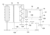
- the feeder 12 includes a drive sprocket 18 provided on a reaper input shaft 17 located at the rear upper portion and a driven rotating body 19 located at the front lower portion in a rectangular cylindrical transport case 16.
- a pair of left and right endless rotation chains 20 are wound and stretched all over.
- a locking transport body (not shown) is bridged at appropriate intervals along the circumferential direction over the left and right endless rotation chains 20, and the rotation transport of the endless rotation chain 20 enables the locking transport body. Is configured to transport the crop transferred from the reaper header 11 rearward and upward.
- the threshing device 4 is located at a low position in the center in the left-right direction of the machine, and the grain tank 5 is located on the front side of the machine above the threshing device 4 and the engine 21 as a power source is located on the rear side of the machine.
- the grain tank 5 and the engine 21 are arranged in the front-rear direction.
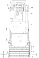
- Aircraft support structure The airframe support structure will be described. As shown in FIGS. 4 and 5, a pair of left and right main frames 22 extending in the longitudinal direction of the vehicle body, a front connecting portion 23 connecting the front of the left and right main frames 22, and a rear connecting the rear of the left and right main frames 22 An airframe frame 25 supporting the entire airframe is configured by the side connecting portion 24.
- the left and right main frames 22 are formed of a channel material having a substantially C-shaped cross section, and are long in the front-rear direction from the front to the rear of the vehicle, as shown in FIGS.
- the left and right traveling units 7, that is, the left and right front wheels 8 and the axles 8 a and 9 a of the left and right rear wheels 9 are provided at positions lower than the left and right main frames 22.
- the left and right front wheels 8 and the left and right rear wheels 9 are provided on the left and right sides of the left and right main frames 22 respectively in the left and right direction of the machine body. Are supported by the front wheels 8 and the left and right rear wheels 9.
- the front connecting portion 23 will be described. As shown in FIGS. 4 and 5, in the front side connecting portion 23, an upper horizontal portion connecting the left and right base portions 26 corresponding to the front projecting portions projecting forward from the left and right main frames 22 and the left and right base portions 26. A frame 27 and a lower horizontal frame 28 connecting the left and right side portions below the left and right base portions 26 are provided.
- the base portion 26 is integrally connected to the front end portions of the left and right main frames 22 so as to project forward.
- the upper horizontal frame 27 is in the form of a rectangular tube and extends over the left and right base portions 26, and the left and right sides are integrally connected to the base portion 26.
- an axle case 29 rotatably supporting an axle of the front wheel 8 is bolted to the lower surface side of the left and right base portions 26 projecting forward from the left and right main frames 22. There is. Therefore, the front side of the main frame 22 is supported by the front wheel 8.
- the left and right axle cases 29 are connected by the lower horizontal frame 28.
- the lower horizontal frame 28 includes left and right front-to-back connection members 30 extending in the front-rear direction, a rear side connection member 31 connecting the rear parts of the left and right front-to-back connection members 30, and front portions of the left and right front-to-back connection members 30. And a front side connector 32 connecting the two.
- a front side connection member 32 is bolted to the left and right axle cases 29.
- a transmission case 34 for mounting a traveling drive A (see FIG. 19) for traveling drive is provided so as to be inserted between the upper horizontal frame 27 and the lower horizontal frame 28. Then, as shown in FIG. 9, on the left and right sides of the transmission case, axle cases 29 for the front wheels 8 on the left and right, and relay transmission cases 35 on the left and right connecting the transmission case 34 and the axle cases 29 on the left and right are provided. It is done.
- the transmission case 34 and the relay transmission case 35 and the relay transmission case 35 and the axle case 29 are respectively flange-connected by bolt fastening. Accordingly, the axle case 29 of the left and right front wheels 8, the left and right relay transmission case 35, and the transmission case 34 are integrally connected.
- the rear lower portions of the left and right axle cases 29 are connected by a horizontal pipe frame 36 made of a round pipe material.
- a horizontal pipe frame 36 made of a round pipe material.
- an internal space is used as a reservoir of hydraulic oil.
- a front end portion of the transmission case 34 is connected to an intermediate portion in the left-right direction of the horizontal pipe frame 36 via a connecting member 37.
- the front connecting portion 23 constitutes a front portion connecting portion that connects the left and right traveling portions 7 (the front wheels 8).
- the rear connection portion 24 will be described. As shown in FIG. 5, the rear side connection portion 24 is provided with a rear connection body 38 made of a round pipe material located below the left and right main frames 22 and extending over the left and right main frames 22.
- a rear wheel support 39 as a traveling device support provided over the rear wheels is swingably supported by the rear connection body 38 around the longitudinal axis P2. That is, the rear wheel support 39 constitutes a rear traveling unit connecting body that connects the left and right traveling units 7 (rear wheels 9).
- the support frame 40 which protrudes downward is provided at the vehicle body rear side location in the main frame 22 on either side, and the rear connection body 38 is bridged and connected over the support frame 40 of the both right and left.
- the rolling support portion 41 is provided in a fixed state at the left and right middle portions of the rear connecting body 38, and the middle portion in the vehicle body width direction of the rear wheel support 39 in the vehicle body direction is swingable around the shaft center P2 in the vehicle front and rear direction. It is supported by the rolling support portion 41.
- the left and right rear wheels 9 are pivotally supported around the longitudinal axis center at the left and right side end portions of the rear wheel support 39, and a steering cylinder 42 is provided on the rear side of the rear wheel support 39 along the left and right direction. It is done.
- the rear wheel 9 can be pivoted about the longitudinal axis center by the operation of the steering cylinder 42.
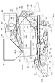
- the threshing apparatus 4 includes a threshing unit 43 that performs a threshing process, and a sorting unit 44 that performs a sorting process on the processed material after the threshing process has been performed by the threshing unit 43.
- the threshing portion 43 is provided with a substantially box-like threshing frame 45 in a state of surrounding the outer peripheral portion, and the threshing barrel 46 that rotates around the rotation axis along the longitudinal direction of the machine is provided inside the threshing frame 45 At 46, the shredded grain of the reaping grain is processed.
- the sorting unit 44 is provided with a sorting unit frame 47 formed of a peripheral wall portion in a rectangular state, and grains and branches are swayed and transferred within the sorting unit frame 47 after the grain shedding processing has been performed.
- a sorting processing unit 48 (see FIGS. 8 and 19) is provided for sorting a second product such as a grain with a grain and waste scraps and the like.
- the threshing part 43 and the sorting part 44 are respectively constituted by the threshing frame 45 and the sorting part frame 47 as a frame structure having a large supporting strength at the outer peripheral part covering the periphery.
- a shredding device 49 is provided which shreds the threshing treatment material (waste straw scraps and the like) after the threshing treatment by the threshing device 4.
- the sorting processing unit 48 provided in the sorting unit 44 is a screw conveyor type that conveys grains that are leaked and sorted while swinging and transferring by the swinging sorting apparatus 50 to one side. It comprises a thing recovery device 51, a screw conveyor type second thing recovery device 52 for conveying the second thing to one side, and a blower 53 for supplying a sort of air to the processing object.
- a grain serving as a first thing conveying device for conveying the grain conveyed by the first thing recovery device 51 toward the upper grain tank 5
- a grain lifting conveyor 54 and a second reduction device 55 for reducing the second conveyed by the second collection device 52 to the threshing part 43 are provided.
- the threshing frame 45 which comprises the threshing part 43 is mounted and supported by the main frame 22 on either side.
- the threshing frame 45 extends substantially in the front-rear direction on both the left and right sides of the threshing part 43, and is substantially plate-shaped as a left-right vertical support extending along the vertical direction.
- a plurality of reinforcing supports and the like surrounding the peripheral portion of the wall portion are integrally connected.
- the front wall portion 58 and the rear wall portion 57 are formed with openings through which the threshing treatment passes.
- the reinforcing support is formed of a rectangular cylinder, an angle member, etc., and as a plurality of reinforcing supports, as shown in FIGS. 6 and 8, left and right lower portions extending in the front and rear direction along lower edges of the left and right side walls 56
- the threshing frame 45 is mounted on and supported by the left and right main frames 22.
- the lower supports 59 and the main frame 22 are connected by bolts at a plurality of locations. It is fixed.
- the left and right main frames 22 are provided in a horizontal state substantially parallel to the ground contact surface when the airframe is in contact with the ground, while the upper part of the threshing device 4 is , It is provided in a rear rising inclination state located on the upper side toward the rear side of the vehicle. That is, the left and right upper supports 60 are provided to be inclined upward and backward along the upper portion of the threshing device 4.
- the driving unit 3 is mounted and supported by a driving unit frame 62 connected and fixed to the threshing frame 45.
- the driver's frame 62 has its base end connected and fixed to the upper side of the left and right vertical frame 61, which is a reinforcing support at the front end of the threshing frame 45, and projects in a cantilever shape toward the front of the machine. It is provided in the state. Further, in the driver frame 62, rod-like left and right reinforcing members in which the middle part in the forward projecting direction is extended diagonally upward from the lower side location than the connection location of the base end in the left and right vertical frame 61 63 received and supported.
- the driving unit frame 62 is provided in a horizontal state so as to be substantially parallel to the ground contact surface.
- the driving unit 3 is surrounded by the cabin 2, and the entire driving unit 3 including the cabin 2 is configured by an integrated box-like body.
- Such an operation unit 3 is mounted on and supported by the operation unit frame 62 via a vibration isolation rubber (not shown) and fixed by bolt connection.
- the cutting and transportation is performed over the upper surface of the base portion 26 as a forward projecting portion protruding forward from the left and right main frames 22 and the front surface of the vertically facing frame 61 as shown in FIG.
- a bearing bracket 64 (see FIG. 6) for supporting the proximal end of the part 1 is received and supported.
- the base end portion is rotatably supported by the bearing bracket 64, and the whole of the reaper transport unit 1 is supported so as to be pivotable around the horizontal axis P1.
- a top plate 65 covering the upper side of the threshing cylinder 46 is curved in a substantially semi-cylindrical shape along the outer peripheral surface of the threshing cylinder 46.
- a threshing upper connection body 66 is provided at the upper side of the top plate 65 to connect the upper portions of the left and right side wall portions 56. As shown in FIGS. 7 and 8, a plurality of threshing upper connection bodies 66 are provided in a plurality in a state where they are appropriately spaced in the longitudinal direction of the machine body.
- the threshing upper connection body 66 is formed in an arc shape so that the lower end edge follows the shape of the top plate 65, and the lower end edge is bolt-connected as appropriate in a state where the lower end edge is in contact with the top plate 65. Thus, the threshing upper connection body 66 is supported by the top plate.
- the sorting unit frame 47 constituting the sorting unit 44 is suspended and supported by the left and right main frames 22.
- the sorting unit frame 47 has a side wall portion 67 covering the left and right sides of the sorting portion 44, and a front support portion 68 connecting the front sides of the left and right side wall portions 67. Is formed. Then, the upper end portions of the left and right side wall portions 67 are put on the lower surfaces of the left and right main frames 22, fixed by bolt connection, and suspended and supported.
- the front end of the sorting unit frame 47 and the front connecting portion 23 of the machine frame 25 are connected. Specifically, the rear horizontal connector 31 in the lower horizontal frame 28 of the front frame 23 of the airframe frame 25 and the front ends of the left and right side walls 67 of the sorting frame 47 are bolted together. It is done.
- the fuel tank 70 is provided between the front wheel 8 and the rear wheel on the left side, and in a state where the fuel tank 70 is located laterally outward of the sorting unit 44.
- a fuel tank support frame 71 for mounting and supporting the fuel tank 70 is provided.
- the fuel tank support frame 71 connects the left and right sides of the lower portion of the sorting unit frame 47, and protrudes outward to the left of the main frame 22 on the left side of the airframe of the left and right main frames 22. It is prepared in the state to do.
- the fuel tank support frame 71 has two laterally facing members 72 extending in the left and right direction separated from each other in the front and rear direction, and two front and rear facings connecting right side end portions of the two laterally facing members 72 and left and right middle portions.
- a member 73 and a tank mounting portion 74 provided at the left end of the two transverse members 72 are provided.
- the transverse member 72 is formed of a square pipe material, and the front and rear member 73 is formed of an angle member.
- a recessed portion 75 in which the laterally oriented member 72 is inserted is formed at a position corresponding to the front and rear laterally oriented members 72.
- the fuel tank support frame 71 is mounted from the lower side of the sorting unit frame 47 so that the front and rear laterally oriented members 72 enter the recessed portion 75, and the two front and rear facing members 73 are lower side with respect to the left and right side wall portions 67. It is bolted and fixed from.
- the tank mounting portion 74 protrudes outward to the left from the side wall portion 67 on the left side of the sorting portion frame 47, and the fuel tank 70 is mounted on and supported by the tank mounting portion 74.
- the grain tank 5 is provided above the threshing device 4 and positioned on the front side of the machine body.
- the grain tank 5 is supported on the top of the threshing frame 45. That is, the grain tank 5 is mounted on and supported by the upper supports 60 on the left and right in the threshing frame 45 via the front tank support frame 76 on the front side of the fuselage, and the rear side of the tank is a rear tank support frame 77. , And is mounted and supported on the left and right upper supports 60.
- the grain tank 5 is provided with a grain discharging device H for discharging the stored grain to the outside of the aircraft.
- a transverse feeding / conveying unit 78 located in the lower inside of the grain tank 5 and laterally feeding grains, and outside the grain tank 5, conveyed by the transverse feeding / conveying unit And a discharge conveyor 79 for conveying the kernels to the discharge point.
- the bottom of the grain tank 5 is formed to be tapered downward in the left-right direction, and the screw type is installed at the lower end of the downward tapered portion in the grain tank 5 as shown in FIGS.
- the transverse transport unit 78 is provided.
- the grain stored is configured to be guided downflow to the cross transport unit 78 at the time of discharge.
- a screw conveyor type discharge conveyor 79 for discharging the grain conveyed by the crossfeed conveyance unit 78 toward the discharge point outside the machine body is provided outside the left side of the grain tank 5. It is equipped.
- the grain tank 5 is formed in a downward tapered shape in the longitudinal direction of the machine body, and the discharge conveyor 79 is in a state in which the base end 80 is supported by the downward tapered slope portion of the grain tank 5 It is equipped.
- the proximal end 80 is rotatably supported around an axis perpendicular to the inclined surface.
- the discharge conveyor 79 is configured to be switchable between a projecting state in which the distal end portion projects outward and a stored state in which it retracts toward the inside of the machine by rotating the base end with the hydraulic cylinder 81. .
- the discharge conveyor 79 In the stored state, the discharge conveyor 79 is inclined upward from the rear side of the machine body as shown in FIG. 2 and, as shown in FIG. It is stored in a state of entering into the insertion portion 82.
- the fuel tank 70 is also housed in the state of entering the lower tapered recess 82 of the grain tank 5 similarly to the discharge conveyor 79.
- the grain tank 5 is supported by the front side tank support frame 76 on the front side in the lower-down inclined posture bottom side, and the rear side on the rear side in the upward-rising posture is the rear side tank support It is supported by a frame 77.
- the front side tank support frame 76 extends over the left and right side walls 56 of the threshing frame 45 and rests on the left and right upper supports 60 located at the upper edge of the left and right side walls 56. It is supported and bolted.
- the rear side tank support frame 77 like the front side tank support frame 76, extends over the left and right side walls 56 of the threshing frame 45 and is located on the upper edge of the left and right side walls 56. It is mounted and supported by
- the rear side tank support frame 77 includes left and right tank side support portions 83 located on the left and right sides, and a plurality of tank left and right tank side support portions 83 connected to each other.
- a connecting portion 84 is provided.
- the left and right tank side supports 83 are each formed in a substantially trapezoidal frame shape in a side view.
- the lower connecting member 84a connecting the lower portions of the left and right tank side support parts 83 among the tank left and right connecting parts 84 is formed in a round pipe shape.
- a rotary shaft for power transmission (counter shaft 138) is rotatably inserted and supported around the center axis in the left-right direction inside the lower connection member 84a.
- the left and right tank side support parts 83 are connected by a plurality of connecting members 84b in addition to the round pipe shaped tank left and right connection parts 84 to secure support strength.
- the driving unit 6 As shown in FIG. 15, the driving unit 6 is supported by the threshing frame 45 in a state of being located on the rear side of the grain tank 5. As shown in FIGS. 1 and 2, the drive unit 6 is covered with the drive unit cover 85 substantially throughout the outer periphery, but as shown in FIGS. 11 and 15 on the inward side of the drive unit cover 85.
- an exhaust treatment device 89 for purifying the exhaust gas from the engine 21.
- the exhaust treatment device 89 includes a diesel particulate filter (DPF) to reduce particulate matter (PM) such as diesel particulates contained in the exhaust gas.
- DPF diesel particulate filter
- PM particulate matter
- the driving unit cover 85 is configured to be easily opened for maintenance work.
- An engine support frame 91 for supporting the engine 21 is provided, and the engine support frame 91 extends over the left and right side walls 56 of the threshing frame 45 and is located at the upper edge of the left and right side walls 56 It is placed on and supported by the support 60.
- the engine support frame 91 includes side vertical surface portions 92 as left and right engine side support portions extending along the front and rear direction above the left and right upper supports 60, and left and right side portions.
- a front connecting member 93 as a front engine left and right connecting part connecting the front of the vertical surface 92 and a rear engine left connecting part connecting the front and rear middle parts of the left and right side vertical surface 92
- a rear support portion 95 for connecting the rear end portions of the left and right side vertical surface portions 92 with each other.
- a work table 96 on which a worker can get on for maintenance work of the drive unit 6, etc. is placed and supported.
- the left and right side vertical surface portions 92 are formed so that the front side of the machine body is wide in the vertical direction, and the width of the rear side of the machine body becomes substantially narrow. Lower end edges of the left and right side vertical surface portions 92 are bolted in a state of being mounted on the left and right upper supports 60.
- an engine mounting portion 97 for mounting and supporting the engine 21 is provided on both left and right sides.
- the engine 21 is mounted and supported by the four engine mounting portions 97 via a rubber mount.
- the rubber mount absorbs the vibration of the engine 21 so that the vibration is not transmitted to the operation unit 3.
- a protection fence 98 for protecting the worker is provided on the outer periphery of the work bench 96.
- the left and right upper supports 60 are provided in an upward-inclined inclined state positioned upward toward the rear of the machine, but the left and right side vertical surface portions 92 are formed so as to gradually narrow toward the rear of the machine. Therefore, the upper edges of the left and right side vertical surface portions 92 are in the horizontal state, and the engine mounting portion 97 and the work bench 96 are respectively provided in the horizontal state.
- the exhaust treatment device 89 and the radiator 88 are separately disposed on the left and right sides with respect to the engine 21 and the radiator 88 is disposed on the right side of the threshing device 4 (in It is provided in the state which protrudes outward on the right side from the edge part of (an example).
- the exhaust gas treatment device 89 is supported by the engine 21, and the radiator 88 is supported by the threshing device 4. As shown in FIG. 14, the exhaust treatment device 89 is mounted on and supported by a bearing member 99 fixed to the casing of the engine 21. The exhaust treatment device 89 and the engine 21 are provided side by side in the left-right direction with the upper end positions being substantially the same height.
- the radiator 88 is supported by a bracket 100 fixed to the right side wall 56 of the threshing frame 45.
- the cooling fan 90 is driven by a hydraulic motor.
- the drive unit 6 is provided with a support frame formed in a frame shape in order to support the drive unit cover 85. The lower end portion of the support frame is supported by the engine support frame 91. The upper portion of the radiator 88 is supported by the support frame and held in posture.
- an air cleaner 86 and a precleaner 87 are provided in a state where the air cleaner 86 and the precleaner 87 are located on the rear side of the engine 21.
- the air cleaner 86 and the precleaner 87 are supported by the engine support frame 91.
- the air cleaner 86 is supported by a support portion 101 located on the lower side and raised from the engine support frame 91.
- a work bench 96 is provided in a state where the air cleaner 86 and the precleaner 87 are located on the rear side of the machine, and maintenance work can be easily performed.
- a ladder 102 is provided at the rear of the work platform 96 for the operator to get on and off the work platform 96 from the outside of the machine body.
- Transmission structure 1 A transmission structure for transmitting the power of the engine 21 to the threshing device 4 and the reaper transport unit 1 will be described. As shown in FIG. 11, the engine 21 is provided in a state in which the output shaft 21A faces in the left-right direction and in a state in which the engine 21 protrudes leftward. As shown in FIG. 11, the engine 21 is provided in a state in which the output shaft 21A faces in the left-right direction and in a state in which the engine 21 protrudes leftward. As shown in FIG.
- a first transmission mechanism D1 (corresponding to a transmission mechanism for threshing drive) for transmitting the power of the engine 21 from the output shaft 21A to the threshing drum drive shaft 105 for driving the threshing drum;
- the power from the threshing drum drive shaft 105 is transmitted to the other driven devices provided in the sorting unit 44, that is, the swing sorting device 50, the first item recovery device 51, the second thing recovery device 52, and the blower 53
- a second transmission mechanism D2 is provided.
- the first transmission mechanism D1 and the second transmission mechanism D2 are disposed to be located on the left side of the engine 21 with respect to the engine 21.
- the throttling gearshift transmits the power transmitted to the threshing drum drive shaft 105 to the threshing drum at an upper side location of the shredding device 49 on the airframe rear side of the threshing device 4.
- a device 106 is provided.
- the threshing drum transmission 106 is surrounded by a case, and as shown in FIG. 19, the power transmitted from the threshing drum drive shaft 105, which is directed leftward and rightward, in the case is shifted up and down in two stages.
- a gear type transmission mechanism for transmitting to the threshing drum shaft 107 directed in the front-rear direction.
- the first transmission mechanism D1 is a belt type transmission mechanism that transmits power from the output shaft 21A of the engine 21 toward the threshing drum drive shaft 105.
- a transmission belt 110 is wound around an output pulley 108 provided on the output shaft 21A and an input pulley 109 provided on the threshing drum drive shaft 105.
- the first transmission mechanism D1 is positioned on the left side of the threshing device 4 and is provided in a slanting back and down state so as to be positioned lower toward the rear side of the machine body, and transmits power toward the lower back side.
- the second transmission mechanism D2 is a threshing input shaft 111 to which power from the threshing drum drive shaft 105 is input and a threshing relay to which power from the threshing input shaft 111 is transmitted. And a shaft 112, and transmits the power from the threshing input shaft 111 to the swing sorting device 50, and the power from the threshing relay shaft 112 is a first item recovery device 51, a second thing recovery device 52, And, it is configured to transmit to the blower 53.
- the second transmission mechanism D 2 includes a belt-type first threshing transmission mechanism 113 that transmits power from the threshing drum drive shaft 105 to the threshing input shaft 111, and a relay shaft 112 for threshing from the threshing input shaft 111.
- a transmission mechanism 117 and a chain transmission mechanism 118 for transmitting power from the threshing input shaft 111 to the swing sorting device 50 (specifically, a swing drive unit) are provided.
- the threshing drum drive shaft 105 is provided at a high position at the rear of the threshing part 43, and the threshing input shaft 111 is on the front side of the fuselage drive shaft 105 and in the lower part of the threshing part 43. It is provided in the state of being located.
- the first threshing transmission mechanism 113 is provided in a forward-down inclined state.
- the second threshing transmission mechanism 114 is provided to extend forward from the threshing input shaft 111 in a substantially horizontal position. Therefore, the first threshing power transmission mechanism 113 and the second threshing power transmission mechanism 114 are disposed in a state of being bent in a substantially L shape projecting downward.
- the fifth threshing transmission mechanism 117 is provided with a blower transmission mechanism 119 formed of a split pulley type belt continuously variable transmission.
- the blower transmission mechanism 119 changes the belt winding diameter by changing the distance between the split pulleys 121 by the cam mechanism 120 incorporated as shown in FIG. it can.
- the operation of the cam mechanism 120 is performed by a manual operation or an operation by an actuator.
- the power transmitted to the first item recovery device 51 is transmitted to the grain lifting conveyor 54. Also, the power transmitted to the second product recovery device 52 is transmitted to the second product reduction device 55.
- a power input pulley 122 as a power input rotary body in which power from the threshing drum drive shaft 105 is input to the threshing input shaft 111 sequentially from the lateral side of the machine, relay for threshing
- the relay pulley 123 as a relay output rotator outputting power to the shaft 112
- the output sprocket 118A as a sorting output rotator in the chain transmission mechanism 118 outputting power to the swing sorting device 50 In the state, they are supported integrally rotatably.
- the relay input pulley 124 as a relay input rotating body to which power from the threshing input shaft 111 is transmitted to the threshing relay shaft 112 sequentially from the lateral side of the machine, the reaper transport section 1.
- An output pulley 125 for cutting and conveying as an output rotating body for cutting and conveying that outputs a power to 1 and a pulley 126 for selecting output as an output rotating body for selecting and outputting a power to a first object recovery device 51 Is supported integrally rotatably.
- a belt type reaping transmission mechanism 127 as a third transmission mechanism D3 for transmitting the power transmitted to the sorting processing unit 48 to the reaper transport unit 1 is provided.
- the reaper transmission mechanism 127 is configured to transmit the power from the threshing relay shaft 112 to the reaper input shaft 17 of the reaper transport unit 1.
- the reaper input shaft 17 functions as a drive shaft of the feeder 12 and is provided in a state of projecting outward from the transport case 16 of the feeder 12 to the left.
- the cutting power transmission mechanism 127 is provided to extend forward from the relaying shaft 112 for threshing in a substantially horizontal posture.
- the reap-and-transfer input pulley 128 as a reap-transfer input rotary member to which power from the threshing relay shaft 112 is transmitted protrudes leftward outward from the transfer case 16 in the reaping input shaft 17. It is integrally rotatably supported by the outward protrusion. Then, among the outwardly projecting portions of the reaper input shaft 17, the rotary reel 13, the cutting blade 14, and the cross feed auger are located at a position located between the reaper transfer input pulley 128 and the feeder 12 (the transfer case 16). A reaping output sprocket 129 as a reaping output rotator that outputs power to 15 is supported integrally rotatably.
- the power from the reaper output sprocket 129 is a reaper relay provided at the rear of the reaper header 11 by a transmission chain 130 extending in the front-rear direction along the left outside of the transfer case 16
- the shaft 131 is transmitted.
- the power from the reaper relay shaft 131 is transmitted to the rotating reel 13 via the reel chain transmission mechanism 132 and the belt transmission mechanism 133, and is transmitted to the crossfeed auger 15 via the auger chain transmission mechanism 134 for cutting blades. It is transmitted to the cutting blade 14 through the belt transmission mechanism 135.
- a belt-type shredding transmission mechanism 136 for transmitting the power from the threshing drum drive shaft 105 to the shredding apparatus 49 is provided.
- the shredding processing transmission mechanism 139 is provided to extend downward from the threshing cylinder drive shaft 105. Therefore, the second transmission mechanism D2 is configured to branch and transmit the power transmitted to the threshing drum drive shaft 105 to the sorting processing unit 48 and the shredding device 49.
- the threshing power transmission system for transmitting the power from the threshing drum drive shaft 105 to the plurality of driven devices provided in the sorting processing unit 48 is collectively provided on the left side of the threshing device 4 ing.
- a power transmission system for cutting that transmits the power from the cutting input shaft 17 to the rotating reel 13, the cutting blade 14, and the cross feed auger 15 is collectively provided on the left side of the cutting conveyance unit 1. Therefore, the power transmission unit for transmitting the power from the output shaft 21A of the engine 21 to the plurality of driven devices provided in the sorting processing unit 48 is disposed on the left side of the engine 21 (an example on one side in the left-right direction). Ru.
- a fourth transmission mechanism D4 for transmitting the power from the engine 21 to the grain discharging device H and the traveling drive A is provided, and on the output shaft 21A of the engine 21, the power of the engine 21 is It branches into a first transmission mechanism D1 and a fourth transmission mechanism D4.
- the counter shaft 138 as a first relay shaft to which power is transmitted from the output shaft 21A of the engine 21 through the transmission belt 137 is provided, and the power of the engine 21 is the right end of the counter shaft 138 Are branched and transmitted to the grain discharging device H and the traveling drive device A. Therefore, the power transmission unit for transmitting the power from the output shaft 21A of the engine 21 to the grain discharging device H and the traveling drive device A is disposed on the right side of the engine 21 with respect to the engine 21.
- the counter shaft 138 which is a rotating shaft for transmission, extends from a lateral portion of the threshing device 4 to the other side in a state of passing through the inside of the round pipe-shaped lower connecting member 84a in the rear side tank support frame 77. It extends and is rotatably supported about a left-right facing axial center. That is, it is provided extending from the left side of the machine body to the right side of the machine as one side in the left-right direction of the machine, and the power from the output shaft 21A is input to the left side of the machine, and the grain discharging device H and travel are
- the driving device A is configured to output power.
- the countershaft 138 is provided in an area surrounded by the upper surface of the threshing device 4 and the grain tank 5 and the engine 21 in a side view.
- a belt-type discharge transmission mechanism 139 for transmitting the power from the counter shaft 138 to the cross feed transport portion 78 of the grain discharging device H, and the threshing portion from the power from the counter shaft 138
- the belt drive type first transmission mechanism 141 for transmitting to the traveling relay shaft 140 as a second relay shaft provided on the front side of the front portion 43 and the power from the traveling relay shaft 140 to the traveling drive device A
- a belt type traveling second transmission mechanism 142 for transmitting is provided.
- the discharge transmission mechanism 139 is provided to extend forward in a substantially horizontal posture.
- the power transmitted from the discharge transmission mechanism 139 is configured to be transmitted to the discharge conveyor 79 located on the left side of the machine body via the cross feed conveyance unit 78.
- the first traveling transmission mechanism 141 is provided to extend from the counter shaft 138 in a forward and downward direction in an inclined posture.
- the traveling drive device A is provided at a lower position of the grain tank 5 in the lower part of the machine body, and the second traveling transmission mechanism 142 is provided to extend downward from the traveling relay shaft 140 in a substantially vertical posture. ing.
- the traveling drive device A does not describe the detailed configuration, but based on the driving operation of the shift operation tool, the turning operation tool, etc. (not shown) provided in the driving unit 3, the driving operation of the left and right front wheels 8 is performed. It is configured to transmit power to drive at a suitable speed. When going straight on, the left and right front wheels 8 are at the same speed or substantially the same speed, and when turning, they are driven with a speed difference.
- the output shaft 21A of the engine 21 is provided at the left side of the machine, and the power transmission unit for transmitting power from each output shaft 21A to the devices of the threshing device 4 and the reaper transport unit 1 is disposed on the left side of the machine There is.
- the countershaft 138 is configured to output power to the grain discharging device H and the traveling drive A from the right side of the machine body. That is, a power transmission unit for transmitting power from the output shaft 21A to the grain discharging device H and the traveling driving device A is disposed on the right side of the machine. Then, the power transmitted from the counter shaft 138 from the right side of the machine is transmitted to the discharge conveyor 79 located on the left side of the machine via the cross feed conveyance unit 78.
- the grain tank 5 is located on the front side of the machine above the threshing device 4, and the engine 21 is located on the rear side of the machine, so that the grain tank 5 and the engine 21 are back and forth.
- the configuration is such that they are arranged in the direction, the engine 21 is located on the front side of the machine above the threshing device 4 and the grain tank 5 is located on the rear side of the machine instead of this configuration.
- only the grain tank 5 may be disposed above the threshing device 4 or only the engine 21 may be disposed above the threshing device 4. May be Alternatively, the grain tank 5 and the engine 21 may be disposed at the side or rear side of the threshing device 4.
- the substantially plate-like side wall portion 56 is provided as the left and right vertical support portions of the threshing frame 45, but instead of this structure, a wall covering the side of the threshing portion Alternatively, a dedicated frame member may be erected from the main frame, and the configuration of the threshing frame can be implemented with various changes.
- the front traveling unit coupling body is configured by the front side coupling unit 23 including the base portion 26, the upper horizontal frame 27, and the lower horizontal frame 28, and the rear traveling unit coupling body
- the rear wheel support body 39 replaces with this structure and employ
- a configuration similar to that of the rear wheel support 39 may be adopted.
- the front side of the left and right main frames 22 is connected by the front side connecting portion 23, and the rear side of the left and right main frames 22 is configured by the rear side connecting portion 24.
- the rear side of the left and right main frames 22 is connected by a connecting portion similar to the front side connecting portion 23, and the left and right main frames 22 are connected by a connecting portion similar to the rear side connecting portion 24.
- the threshing upper connection body 66 connecting the upper portions of the left and right vertical support portions is provided, and the threshing upper connection body 66 is connected to the top plate 65 of the threshing device 4.
- the threshing upper connection body 66 may not be connected to the top plate 65 of the threshing device 4.
- the transmission case 34 is provided to be inserted between the upper horizontal frame 27 and the lower horizontal frame 28.
- the transmission case 34 includes the upper horizontal frame 27 and the lower horizontal frame 28.
- the configuration may be such that a portion protrudes outward from the region between the two.
- the base end of the reaper transport unit 1 is supported over the upper surfaces of the left and right base portions 26 and the front surface of the vertically oriented frame body of the threshing frame 45.
- the base end of the reaper transport unit 1 may be supported by the left and right main frames 22 at a location apart from the vertically oriented frame body of the threshing frame 45.
- the exhaust treatment device 89 and the radiator 88 are separately disposed on the left and right sides with respect to the engine 21 in the longitudinal direction of the airframe, but instead of this configuration, the exhaust treatment device It may be configured to be provided above the engine.
- the traveling unit includes the front wheel 8 as the front traveling device and the rear wheel 9 as the rear traveling device.
- the front traveling device and the rear One of the side traveling devices may be constituted by the crawler traveling device and the other may be constituted by the wheels, or the front traveling device and the rear traveling device may be respectively constituted by the crawler traveling device.
- the left and right traveling units may be configured by one crawler traveling device.
- the present invention can also be applied to self-release type combine that threshs the tip side while holding and conveying the stock origin of the mowing grain gutter with a feed chain, in addition to the ordinary type combine.
Landscapes
- Life Sciences & Earth Sciences (AREA)
- Environmental Sciences (AREA)
- Harvester Elements (AREA)
- Combines (AREA)
Abstract
コンバインは、機体前後方向に延びる左右の主フレーム22と、左右の主フレーム22の間に配設された脱穀装置4とが備えられ、脱穀装置4に、脱粒処理を行う脱穀部43と、脱穀部43の下方に設けられ、脱穀部43による脱粒処理が行われた後の処理物を選別処理する選別部44とが備えられ、脱穀部43を構成する脱穀フレーム45が左右の主フレーム22に載置支持され、選別部44を構成する選別部フレーム47が左右の主フレーム22に吊り下げ支持されている。
Description
本発明は、走行しながら植立穀稈を刈り取り、刈取穀稈を脱穀装置にて脱穀処理するように構成されているコンバインに関する。
脱穀装置は、脱穀処理を行う脱穀部と、脱穀部による脱穀処理が行われた後の処理物を選別処理する選別部とが、上下方向に並ぶ状態で備えられる。そして、従来では、脱穀部と選別部とが略箱状に形成されたケース内に一体的に収納され、脱穀装置全体が車体の下部に設けられたメインフレームにて載置支持されていた(例えば、特許文献1参照)。
上記従来構成では、ケース内に脱穀部と選別部とが上下方向に並ぶ状態で備えられるので、脱穀装置全体が大型になり、脱穀装置を機体に組付ける際に組付け作業が行い難いものとなる不利があった。
最近では、コンバインにおいて、作業処理能力を向上させることが要望されており、作業処理能力の向上に伴って脱穀装置も更に大型化させる必要がある。しかし、上記従来構成では、脱穀装置を大型化させようとすると、外形形状が大型化するとともに、重量もさらに大になり、組付け作業が行い難いものになるおそれがある。
しかも、上記従来構成では、脱穀装置を高能力化させようとすると、脱穀装置が上下方向に背高になる。その結果、機体の上下高さが大となり、重心位置が高くなって、走行安定性が悪化する不利もある。
そこで、機体の上下高さを抑制するとともに、脱穀装置の組付け作業を行い易いものにすることが望まれていた。
本発明に係るコンバインの特徴構成は、
機体前後方向に延びる左右の主フレームと、左右の前記主フレームの間に配設された脱穀装置とが備えられ、
前記脱穀装置に、脱粒処理を行う脱穀部と、前記脱穀部の下方に設けられ、前記脱穀部による脱粒処理が行われた後の処理物を選別処理する選別部とが備えられ、
前記脱穀部を構成する脱穀フレームが左右の前記主フレームに載置支持され、
前記選別部を構成する選別部フレームが左右の前記主フレームに吊り下げ支持されている点にある。
機体前後方向に延びる左右の主フレームと、左右の前記主フレームの間に配設された脱穀装置とが備えられ、
前記脱穀装置に、脱粒処理を行う脱穀部と、前記脱穀部の下方に設けられ、前記脱穀部による脱粒処理が行われた後の処理物を選別処理する選別部とが備えられ、
前記脱穀部を構成する脱穀フレームが左右の前記主フレームに載置支持され、
前記選別部を構成する選別部フレームが左右の前記主フレームに吊り下げ支持されている点にある。
本構成によれば、脱穀部と選別部とは、脱穀フレームと選別部フレームという夫々別のフレームにより別体に構成されている。そして、脱穀フレームは、左右の主フレームの上側に位置して、左右の主フレームに載置支持される。選別部フレームは、左右の主フレームの下側に位置して、左右の主フレームに吊り下げ支持される。
脱穀部と選別部とが別体で構成されるので、脱穀装置を機体に組付ける場合には、脱穀部と選別部とを夫々各別に主フレームに取り付けることができるので、脱穀装置全体を一挙に取り付ける場合に比べて、組付け対象となる装置は外形形状が小型になるとともに、重量も少ないので、組付け作業が行い易い。
選別部フレームは、主フレームの下側に位置して吊り下げ支持されるので、脱穀装置全体としては、主フレームに対して下方側に下がった状態となる。その結果、脱穀装置が大型化して脱穀装置自体は上下方向に背高になったとしても、選別部は主フレームよりも下側に位置するので、機体全体の上下高さが大きくなることを回避できる。
従って、機体の上下高さを抑制するとともに、脱穀装置の組付け作業を行い易いものにすることが可能となった。
本発明においては、
機体左右両側に走行部が備えられ、
左右の前記主フレームよりも低い位置に前記走行部の車軸が備えられ、
左右の前記走行部は、左右の前記主フレームよりも機体左右方向外側に位置する状態で備えられ、
左右の前記主フレームは、左右の前記走行部に支持されていると好適である。
機体左右両側に走行部が備えられ、
左右の前記主フレームよりも低い位置に前記走行部の車軸が備えられ、
左右の前記走行部は、左右の前記主フレームよりも機体左右方向外側に位置する状態で備えられ、
左右の前記主フレームは、左右の前記走行部に支持されていると好適である。
本構成によれば、左右の走行部は、左右の主フレームによりも低い位置に車軸があり、しかも、主フレームの機体左右方向外方側に位置するので、左右の走行部は、左右方向の間隔が大きく、しかも、主フレームよりも低い位置で、安定的に機体全体を支持することができる。
本発明においては、左右の前記走行部を連結する走行部連結体が備えられていると好適である。
本構成によれば、左右の走行部が走行部連結体によって連結されるので、左右の走行部の支持構造の剛性が大になり、強固に支持できる。
本発明においては、
前記選別部フレームの下部の左右両側部を連結するとともに、左右の前記主フレームのうち機体左右方向一方側の前記主フレームよりも機体左右方向一方側外方に突出する燃料タンク支持フレームが備えられ、
前記燃料タンク支持フレームに燃料タンクが載置支持されていると好適である。
前記選別部フレームの下部の左右両側部を連結するとともに、左右の前記主フレームのうち機体左右方向一方側の前記主フレームよりも機体左右方向一方側外方に突出する燃料タンク支持フレームが備えられ、
前記燃料タンク支持フレームに燃料タンクが載置支持されていると好適である。
本構成によれば、選別部フレームの下部の左右両側部を連結して左右方向に沿って延びる状態でタンク支持フレームが備えられる。このタンク支持フレームは、主フレームよりも機体左右方向一方側外方に突出しており、その突出している箇所に燃料タンクが載置支持される。このように選別部を構成するために剛性が大である選別部フレームを有効利用して、燃料タンク支持フレームが安定的に強固に支持され、主フレームよりも機体左右方向一方側外方側にて主フレームに干渉することの無い状態で燃料タンクを支持することができる。
本発明においては、
前記脱穀部の前方に運転部が備えられ、
前記脱穀フレームの前端部における左右両側に左右の縦向きフレーム体が備えられ、
左右の前記縦向きフレーム体から機体前方に向けて突出する状態で運転部フレームが設けられ、
前記運転部フレームに前記運転部が載置支持されていると好適である。
前記脱穀部の前方に運転部が備えられ、
前記脱穀フレームの前端部における左右両側に左右の縦向きフレーム体が備えられ、
左右の前記縦向きフレーム体から機体前方に向けて突出する状態で運転部フレームが設けられ、
前記運転部フレームに前記運転部が載置支持されていると好適である。
本構成によれば、脱穀フレームにおける左右の縦向きフレーム体から機体前方に向けて突出する状態でキャビンフレームが備えられ、そのキャビンフレームにキャビンが載置支持されている。従って、例えば、主フレームから長い支持部材等を延設することなく、脱穀部を構成するために剛性が大である脱穀フレームを有効に利用してキャビンを支持することができる。
本発明においては、
機体前部に、植立穀稈を刈り取り、且つ、刈り取った穀稈を前記脱穀装置に搬送する刈取搬送部が備えられ、
前記脱穀フレームの前端部における左右両側に左右の縦向きフレーム体が備えられ、
左右の前記主フレームのうち左右の前記縦向きフレーム体よりも前方に突出している前方突出部の上面と前記縦向きフレーム体の前面とにわたって、前記刈取搬送部の基端部が支持されていると好適である。
機体前部に、植立穀稈を刈り取り、且つ、刈り取った穀稈を前記脱穀装置に搬送する刈取搬送部が備えられ、
前記脱穀フレームの前端部における左右両側に左右の縦向きフレーム体が備えられ、
左右の前記主フレームのうち左右の前記縦向きフレーム体よりも前方に突出している前方突出部の上面と前記縦向きフレーム体の前面とにわたって、前記刈取搬送部の基端部が支持されていると好適である。
本構成によれば、左右の主フレームから前方に突出している前方突出部と脱穀フレームにおける縦向きフレーム体とによって形成される角部を利用して、刈取搬送部の基端部が支持されている。
従って、脱穀フレームの構成を利用して、刈取搬送部の基端部を支持することができ、特別な回動支点部を別途設ける等の構造の複雑化を招くことなく、安定的に支持することができる。
本発明においては、
機体左右両側に走行部が備えられ、
左右の前記走行部には、前側走行装置と後側走行装置とが備えられ、
左右の前記主フレームの前部は前記前側走行装置に支持され、左右の前記主フレームの後部は前記後側走行装置に支持されていると好適である。
機体左右両側に走行部が備えられ、
左右の前記走行部には、前側走行装置と後側走行装置とが備えられ、
左右の前記主フレームの前部は前記前側走行装置に支持され、左右の前記主フレームの後部は前記後側走行装置に支持されていると好適である。
本構成によれば、左右両側の前側走行装置によって左右の主フレームを介して機体前部側が支持され、左右両側の後側走行装置によって左右の主フレームを介して機体後部側が支持される。従って、左右で夫々前後両側に位置する4つの走行装置によって機体全体が安定的に支持される。
本発明においては、左右の前記主フレームの前部を連結する前側連結部と、左右の前記主フレームの後部を連結する後側連結部とが備えられていると好適である。
本構成によれば、左右の主フレームは、前部側が前側連結部により連結され、後部側が後側連結部により連結される。従って、矩形枠状に連結されるので、全体の剛性を高めることができ、機体全体を強固に支持することができる。
本発明においては、前記選別部の前方側に前記前側連結部が備えられ、前記選別部の後方側に前記後側連結部が備えられていると好適である。
本構成によれば、前側連結部及び後側連結部は、選別部に干渉しない適切な位置において左右の主フレームを良好に連結することができる。
本発明においては、前記選別部フレームの前端部と前記前側連結部とが連結されていると好適である。
本構成によれば、選別部フレームの前端部と前側連結部とを連結することにより、機体支持構造の剛性を一層高めることができる。
本発明においては、前記前側連結部に、左右の前記主フレームの前部に備えられたベース部と、左右の前記ベース部を連結する上部横フレームと、左右の前記ベース部よりも下側において左右の前記ベース部を連結する下部横フレームとが備えられ、左右の前記ベース部の下部が左右の前記前側走行装置に支持されていると好適である。
本構成によれば、前側連結部は、上部横フレームと下部横フレームにより左右両側部同士が連結されるので、上下両側において強固に左右の主フレームを連結することができる。そして、前方突出部の下部が前側走行装置に支持されるので、大型の部材である主フレームを直接に前側走行装置に支持させる構成に比べて加工の手間が少なくなる。
本発明においては、
機体前部に、植立穀稈を刈り取り、且つ、刈り取った穀稈を前記脱穀装置に搬送する刈取搬送部が備えられ、
前記下部横フレームに、前記選別部フレームの前端部の左右両側部に連結され且つ前方に向けて前後方向に沿って延びる左右の前後向き連結体と、左右の前記前後向き連結体の後部を連結する後側横向き連結体と、左右の前記前後向き連結体の前部を連結する前側横向き連結体とが備えられ、
前記前側横向き連結体に前記刈取搬送部を昇降操作可能なアクチュエータが支持されていると好適である。
機体前部に、植立穀稈を刈り取り、且つ、刈り取った穀稈を前記脱穀装置に搬送する刈取搬送部が備えられ、
前記下部横フレームに、前記選別部フレームの前端部の左右両側部に連結され且つ前方に向けて前後方向に沿って延びる左右の前後向き連結体と、左右の前記前後向き連結体の後部を連結する後側横向き連結体と、左右の前記前後向き連結体の前部を連結する前側横向き連結体とが備えられ、
前記前側横向き連結体に前記刈取搬送部を昇降操作可能なアクチュエータが支持されていると好適である。
本構成によれば、下部横フレームは、左右の前後向き連結体、後側横向き連結体、及び、前側横向き連結体を互いに連結して略矩形枠状に構成されるので、剛性を高めることができるとともに、主フレームだけでなく、主要なフレーム部材である選別部フレームを利用して支持強度を高めることができる。
本発明においては、走行駆動用の伝動機構を内装するミッションケースが、前記上部横フレームと前記下部横フレームとの間に入り込む状態で備えられていると好適である。
本構成によれば、ミッションケースは、上部横フレームと下部横フレームとにより、上下両側が囲まれるので、外部の障害物が干渉することを防止することができる。
本発明においては、
前記ミッションケースの左右側方に、左右の前記前側走行装置の車軸ケースと、前記ミッションケースと左右の前記車軸ケースとを連結する左右の中継伝動ケースとが備えられ、
左右の前記車軸ケースは、夫々、左右の前記前方突出部に連結されるとともに、前記下部横フレームに連結されていると好適である。
前記ミッションケースの左右側方に、左右の前記前側走行装置の車軸ケースと、前記ミッションケースと左右の前記車軸ケースとを連結する左右の中継伝動ケースとが備えられ、
左右の前記車軸ケースは、夫々、左右の前記前方突出部に連結されるとともに、前記下部横フレームに連結されていると好適である。
本構成によれば、ミッションケースからの動力は、左右の車軸ケース内の伝動軸、及び、左右の中継伝動ケース内の伝動機構を介して左右の前側走行装置に伝達される。左右の車軸ケースは、下部横フレームにて連結されて剛性を高めた状態で、前方突出部を介して主フレームに強固に支持される。
本発明においては、
前記後側連結部には、左右の前記主フレームよりも下側に位置し且つ左右の前記主フレームにわたって延びる後部連結体が備えられ、
左右の前記後側走行装置にわたって設けられた走行装置支持体が、前記後部連結体に前後軸芯周りに揺動自在に支持されていると好適である。
前記後側連結部には、左右の前記主フレームよりも下側に位置し且つ左右の前記主フレームにわたって延びる後部連結体が備えられ、
左右の前記後側走行装置にわたって設けられた走行装置支持体が、前記後部連結体に前後軸芯周りに揺動自在に支持されていると好適である。
本構成によれば、後側では、左右の主フレームにわたって延びて強固に支持される後部連結体により、走行装置支持体を支持することができる。左右の後側走行装置を支持する走行装置支持体が、後部連結体に前後軸芯周りに揺動自在に支持されるので、左右の後側走行装置は、地面の凹凸に追従しながら左右にローリング作動することができる。
本発明においては、
前記脱穀装置にて脱粒処理されたあとの穀粒を貯留する穀粒タンクと、動力源としてのエンジンとが備えられ、
前記脱穀装置の上方において、機体前部側に前記穀粒タンクが位置し、機体後部側に前記エンジンが位置する状態で、前記穀粒タンクと前記エンジンとが前後方向に並ぶ方向で備えられ、
前記穀粒タンク及び前記エンジンは、機体前後方向に沿って幅広に設けられる状態で左右の前記主フレームから立設される左右の縦向き支持部にて支持されていると好適である。
前記脱穀装置にて脱粒処理されたあとの穀粒を貯留する穀粒タンクと、動力源としてのエンジンとが備えられ、
前記脱穀装置の上方において、機体前部側に前記穀粒タンクが位置し、機体後部側に前記エンジンが位置する状態で、前記穀粒タンクと前記エンジンとが前後方向に並ぶ方向で備えられ、
前記穀粒タンク及び前記エンジンは、機体前後方向に沿って幅広に設けられる状態で左右の前記主フレームから立設される左右の縦向き支持部にて支持されていると好適である。
本構成によれば、脱穀装置の上方の領域を利用して穀粒タンクとエンジンとを配備するので、例えば、脱穀装置を高能力化させるために脱穀装置が大型になる場合であっても、脱穀装置の横側にエンジンを設けたり、穀粒タンクの横側にエンジンを設ける場合に比べて、機体の横幅寸法を大型化させることなく、合理的にエンジンを配備することができる。しかも、穀粒タンク及びエンジンを、機体前後方向の広い範囲にわたって設けられた左右の縦向き支持部にて安定的に支持することができる。
本発明においては、左右の前記縦向き支持部の上部を連結する脱穀上部連結体が備えられ、前記脱穀上部連結体は、前記脱穀装置の天板に連結されていると好適である。
本構成によれば、左右の縦向き支持部の上部、脱穀上部連結体、及び、脱穀装置の天板の夫々が、互いに連結され、しかも、左右の縦向き支持部の下部は左右の主フレームに連結されているので、それらが枠組み状態で剛性が高い強固な支持構造を形成することができる。
本発明においては、
前記穀粒タンクを支持する穀粒タンク支持フレームと、前記エンジンを支持するエンジン支持フレームとが備えられ、
前記穀粒タンク支持フレーム及び前記エンジン支持フレームは、左右の前記縦向き支持部にわたって延び且つ左右の前記縦向き支持部夫々に支持されていると好適である。
前記穀粒タンクを支持する穀粒タンク支持フレームと、前記エンジンを支持するエンジン支持フレームとが備えられ、
前記穀粒タンク支持フレーム及び前記エンジン支持フレームは、左右の前記縦向き支持部にわたって延び且つ左右の前記縦向き支持部夫々に支持されていると好適である。
本構成によれば、穀粒タンクは穀粒タンク支持フレームによって安定的に支持され、エンジンはエンジン支持フレームによって安定的に支持される。また、穀粒タンク支持フレームとエンジン支持フレームは、夫々、左右の縦向き支持部に支持されるので、穀粒タンク支持フレームとエンジン支持フレームを利用して、剛性が高い強固な支持構造を形成することができる。
本発明においては、
動力源としてのエンジンと、エンジン冷却用のラジエータと、前記エンジンからの排気を処理する排気処理装置とが、前記脱穀装置の上方に位置する状態で備えられ、
機体前後方向視で、前記排気処理装置と前記ラジエータとが前記エンジンに対して左右両側に振り分け配置され、且つ、前記ラジエータが前記脱穀装置の左右方向一方側端部よりも左右方向一方側外方に突出する状態で備えられ、
前記排気処理装置は前記エンジンに支持され、
前記ラジエータは前記脱穀装置に支持されていると好適である。
動力源としてのエンジンと、エンジン冷却用のラジエータと、前記エンジンからの排気を処理する排気処理装置とが、前記脱穀装置の上方に位置する状態で備えられ、
機体前後方向視で、前記排気処理装置と前記ラジエータとが前記エンジンに対して左右両側に振り分け配置され、且つ、前記ラジエータが前記脱穀装置の左右方向一方側端部よりも左右方向一方側外方に突出する状態で備えられ、
前記排気処理装置は前記エンジンに支持され、
前記ラジエータは前記脱穀装置に支持されていると好適である。
本構成によれば、排気処理装置とラジエータとがエンジンに対して上方に突出することがなく、エンジン、排気処理装置、及び、ラジエータを、上下方向にコンパクトに収めた状態で配備することができる。
排気処理装置は、高温の排気ガスを処理するものであるから、エンジンにより支持している。ラジエータは、エンジンとの間は冷却水の循環路にて接続されるだけであり、しかも、排気ガスの通流箇所のように高温になることはないので、脱穀装置により支持している。このように排気処理装置とラジエータとを、エンジンに近い位置にて適切に配備することができる。
以下、図面に基づいて、本発明に係るコンバインの実施形態を普通型コンバインに適用した場合について説明する。
〔全体構成〕
図1~図3に示すように、コンバインは、作物を刈り取って後方に搬送する刈取搬送部1、キャビン2にて覆われた運転部3、刈取搬送部1にて刈り取られた作物の脱穀処理を行う脱穀装置4、その脱穀装置4にて脱穀処理されて得られた穀粒を貯留する穀粒タンク5、動力源としてのエンジン21を有する原動部6、機体左右両側に位置する左右の走行部7等が備えられている。左右の走行部7は夫々、操向不能で且つ回転駆動される前側走行装置としての前車輪8と、操向操作可能な後側走行装置としての後車輪9とを備えている。
図1~図3に示すように、コンバインは、作物を刈り取って後方に搬送する刈取搬送部1、キャビン2にて覆われた運転部3、刈取搬送部1にて刈り取られた作物の脱穀処理を行う脱穀装置4、その脱穀装置4にて脱穀処理されて得られた穀粒を貯留する穀粒タンク5、動力源としてのエンジン21を有する原動部6、機体左右両側に位置する左右の走行部7等が備えられている。左右の走行部7は夫々、操向不能で且つ回転駆動される前側走行装置としての前車輪8と、操向操作可能な後側走行装置としての後車輪9とを備えている。
この実施形態で、機体の前後方向を定義するときは、作業状態における機体進行方向に沿って定義し、機体の左右方向を定義するときは、機体進行方向視で見た状態で左右を定義する。すなわち、図1,2,3に符号(F)で示す方向が機体前側、図1,2,3に符号(B)で示す方向が機体後側である。図3に符号(L)で示す方向が機体左側、図3に符号(R)で示す方向が機体右側である。
刈取搬送部1は、機体の前部において、昇降用アクチュエータとしての刈取昇降シリンダ10により横向き支点P1周りで駆動昇降自在に支持されている。刈取搬送部1は、植立する作物を刈り取り、刈り取った作物を刈幅方向の中央部に寄せ集める刈取ヘッダ11と、刈り取られて中央に寄せ集められた作物を機体後方の脱穀装置4に向けて搬送するフィーダ12とを備えている。
図1,2,3,20に示すように、刈取ヘッダ11には、刈取対象となる作物の穂先側を後方に向けて掻込む回転リール13、作物の株元を切断して刈り取るバリカン型の刈刃14、刈り取った作物を刈幅方向の中央部に寄せ集める横送りオーガ15等が備えられている。
フィーダ12は、図20に示すように、角筒状の搬送ケース16内に、後上部に位置する刈取入力軸17に備えられた駆動スプロケット18と、前下部に位置する従動回転体19とに亘って左右一対の無端回動チェーン20が巻回張設されている。左右の無端回動チェーン20にわたり周方向に沿って適宜間隔をあけて係止搬送体(図示せず)を架設してあり、無端回動チェーン20を回動駆動することで、係止搬送体によって刈取ヘッダ11から受け渡された作物を後方上方に向けて搬送するように構成されている。
脱穀装置4は、機体左右方向中央部の低い位置にあり、脱穀装置4の上方において、機体前部側に穀粒タンク5が位置し、機体後部側に動力源としてのエンジン21が位置する状態で、穀粒タンク5とエンジン21とが前後方向に並ぶ方向で備えられている。
〔機体支持構造〕
機体支持構造について説明する。
図4,5に示すように、機体前後方向に延びる左右一対の主フレーム22と、左右の主フレーム22の前部を連結する前側連結部23と、左右の主フレーム22の後部を連結する後側連結部24とによって、機体全体を支持する機体フレーム25が構成されている。
機体支持構造について説明する。
図4,5に示すように、機体前後方向に延びる左右一対の主フレーム22と、左右の主フレーム22の前部を連結する前側連結部23と、左右の主フレーム22の後部を連結する後側連結部24とによって、機体全体を支持する機体フレーム25が構成されている。
左右の主フレーム22は、断面形状が略C形のチャンネル材にて構成され、図1,2に示すように、機体前部から機体後部にわたって前後方向に長く設けられている。左右の主フレーム22よりも低い位置に左右の走行部7すなわち、左右の前車輪8及び左右の後車輪9の車軸8a,9aが備えられている。図4,5に示すように、左右の前車輪8及び左右の後車輪9は、左右の主フレーム22夫々の機体左右方向外方側に位置する状態で備えられ、左右の主フレーム22は左右の前車輪8及び左右の後車輪9に支持されている。
前側連結部23について説明する。
図4,5に示すように、前側連結部23には、左右の主フレーム22から前方に突出している前方突出部に相当する左右のベース部26と、左右のベース部26を連結する上部横フレーム27と、左右のベース部26よりも下側において左右両側部を連結する下部横フレーム28とが備えられている。ベース部26は、左右の主フレーム22の前端部に前方に突出する状態で一体的に連結されている。上部横フレーム27は角筒状であり、左右のベース部26に亘って延び、左右両側がベース部26に一体的に連結されている。
図4,5に示すように、前側連結部23には、左右の主フレーム22から前方に突出している前方突出部に相当する左右のベース部26と、左右のベース部26を連結する上部横フレーム27と、左右のベース部26よりも下側において左右両側部を連結する下部横フレーム28とが備えられている。ベース部26は、左右の主フレーム22の前端部に前方に突出する状態で一体的に連結されている。上部横フレーム27は角筒状であり、左右のベース部26に亘って延び、左右両側がベース部26に一体的に連結されている。
図7,9にも示すように、左右の主フレーム22から前方に突出している左右のベース部26の下面側に、前車輪8の車軸を回転自在に支持する車軸ケース29がボルト連結されている。従って、主フレーム22の前部側が前車輪8に支持されている。
左右の車軸ケース29が下部横フレーム28によって連結されている。
下部横フレーム28には、前後方向に延びる左右の前後向き連結体30と、左右の前後向き連結体30の後部を連結する後側横向き連結体31と、左右の前後向き連結体30の前部を連結する前側横向き連結体32とが備えられている。前側横向き連結体32が左右の車軸ケース29にボルト連結されている。
下部横フレーム28には、前後方向に延びる左右の前後向き連結体30と、左右の前後向き連結体30の後部を連結する後側横向き連結体31と、左右の前後向き連結体30の前部を連結する前側横向き連結体32とが備えられている。前側横向き連結体32が左右の車軸ケース29にボルト連結されている。
走行駆動用の走行駆動装置A(図19参照)を内装するミッションケース34が、上部横フレーム27と下部横フレーム28との間に入り込む状態で備えられている。そして、図9に示すように、ミッションケースの左右側方に、左右の前車輪8の車軸ケース29と、ミッションケース34と左右の車軸ケース29とを連結する左右の中継伝動ケース35とが備えられている。ミッションケース34と中継伝動ケース35との間、及び、中継伝動ケース35と車軸ケース29との間は、夫々、ボルト締結によりフランジ連結されている。従って、左右の前車輪8の車軸ケース29と、左右の中継伝動ケース35と、ミッションケース34とが一体的に連結されている。
左右の車軸ケース29の後下部側箇所同士が丸パイプ材からなる横向きパイプフレーム36にて連結されている。この横向きパイプフレーム36は、内部の空間が作動油の貯留部として利用されている。また、ミッションケース34の前端部が連結部材37を介して横向きパイプフレーム36の左右方向の中間部に連結されている。
以上の説明から明らかなように、前側連結部23によって、左右の走行部7(前車輪8)同士を連結する前部側の走行部連結体が構成されている。
後側連結部24について説明する。
図5に示すように、後側連結部24には、左右の主フレーム22よりも下側に位置し且つ左右の主フレーム22にわたって延びる丸パイプ材からなる後部連結体38が備えられ、左右の後車輪にわたって設けられた走行装置支持体としての後輪支持体39が、後部連結体38に前後軸芯P2周りに揺動自在に支持されている。つまり、後輪支持体39によって、左右の走行部7(後車輪9)を連結する後部側の走行部連結体を構成する。
図5に示すように、後側連結部24には、左右の主フレーム22よりも下側に位置し且つ左右の主フレーム22にわたって延びる丸パイプ材からなる後部連結体38が備えられ、左右の後車輪にわたって設けられた走行装置支持体としての後輪支持体39が、後部連結体38に前後軸芯P2周りに揺動自在に支持されている。つまり、後輪支持体39によって、左右の走行部7(後車輪9)を連結する後部側の走行部連結体を構成する。
すなわち、左右の主フレーム22における車体後部側箇所に、下向きに突出する支持枠40が備えられ、後部連結体38が、その左右両側の支持枠40に亘って架設連結されている。後部連結体38の左右中間部に固定状態でローリング支持部41が設けられ、車体横向きの後輪支持体39の車体横幅方向の中間部が、車体前後向きの軸芯P2周りで揺動自在にローリング支持部41に支持されている。
後輪支持体39の左右両側端部には、左右の後車輪9が縦軸芯周りで揺動自在に支持され、後輪支持体39の後部側に左右方向に沿ってステアリングシリンダ42が設けられている。後車輪9は、ステアリングシリンダ42の操作により、縦軸芯周りで揺動して旋回操作することができる。
〔脱穀装置〕
次に、脱穀装置4について説明する。
図6,7,8,9に示すように、脱穀装置4には、脱粒処理を行う脱穀部43と、脱穀部43による脱粒処理が行われた後の処理物を選別処理する選別部44とが備えられている。脱穀部43は、外周部を囲う状態で略箱状の脱穀フレーム45が備えられ、脱穀フレーム45の内部に、機体前後方向に沿う回転軸芯周りで回転する扱胴46が備えられ、扱胴46によって刈取穀稈の脱粒処理が行われる。
次に、脱穀装置4について説明する。
図6,7,8,9に示すように、脱穀装置4には、脱粒処理を行う脱穀部43と、脱穀部43による脱粒処理が行われた後の処理物を選別処理する選別部44とが備えられている。脱穀部43は、外周部を囲う状態で略箱状の脱穀フレーム45が備えられ、脱穀フレーム45の内部に、機体前後方向に沿う回転軸芯周りで回転する扱胴46が備えられ、扱胴46によって刈取穀稈の脱粒処理が行われる。
選別部44は、矩形状態の周壁部からなる選別部フレーム47が備えられ、選別部フレーム47の内部において、脱粒処理が行われた後の処理物を、揺動移送しながら、穀粒、枝付き穀粒等の二番物、及び、排ワラ屑等に選別するための選別処理部48(図8,19参照)を備えている。
このように、脱穀部43及び選別部44は、夫々、周囲を覆う外周部分が大きな支持強度を有するフレーム構造体としての脱穀フレーム45及び選別部フレーム47にて構成されている。脱穀装置4の機体後方側には、脱穀装置4にて脱穀処理された後の脱穀処理物(排ワラ屑等)を細断処理する細断処理装置49が備えられている。
図19に示すように、選別部44に備えられる選別処理部48は、揺動選別装置50によって揺動移送しながら漏下選別される穀粒を横一側に搬送するスクリューコンベア式の一番物回収装置51と、二番物を横一側に搬送するスクリューコンベア式の二番物回収装置52と、処理物に選別風を供給する送風装置53とを備えている。
図16に示すように、選別部44の右側外方には、一番物回収装置51によって搬送される穀粒を上方の穀粒タンク5内に向けて搬送する一番物搬送装置としての穀粒揚送コンベア54と、二番物回収装置52によって搬送される二番物を脱穀部43に還元するための二番物還元装置55とが備えられている。
そして、脱穀部43を構成する脱穀フレーム45が左右の主フレーム22に載置支持されている。
図6,9,14に示すように、脱穀フレーム45は、脱穀部43の左右両側において、前後方向全域に亘って延びるとともに、上下方向に沿って延びる左右の縦向き支持部としての略板状の側壁部56、左右の側壁部56の後端部同士を連結する略板状の後壁部57、左右の側壁部56の前端部同士を連結する略板状の前壁部58、上記各壁部の周縁部分を囲う複数の補強用支持体等を備えて、それらが一体的に連結されている。前壁部58及び後壁部57には、脱穀処理物が通過するための開口が形成されている。
図6,9,14に示すように、脱穀フレーム45は、脱穀部43の左右両側において、前後方向全域に亘って延びるとともに、上下方向に沿って延びる左右の縦向き支持部としての略板状の側壁部56、左右の側壁部56の後端部同士を連結する略板状の後壁部57、左右の側壁部56の前端部同士を連結する略板状の前壁部58、上記各壁部の周縁部分を囲う複数の補強用支持体等を備えて、それらが一体的に連結されている。前壁部58及び後壁部57には、脱穀処理物が通過するための開口が形成されている。
補強用支持体は角筒材やアングル材等からなり、複数の補強用支持体として、図6,8に示すように、左右の側壁部56の下縁に沿って前後方向に延びる左右の下部支持体59、左右の側壁部56の上縁に沿って前後方向に延びる左右の上部支持体60、前壁部58の左右端縁に沿って縦方向に延びる左右の縦向きフレーム体61等が備えられている。
脱穀フレーム45は、左右の主フレーム22に載置支持されている。説明を加えると、脱穀フレーム45のうちの左右の下部支持体59が左右の主フレーム22の上面に載置された状態で、下部支持体59と主フレーム22とが複数箇所においてボルトで連結して固定されている。
図6に示すように、左右の主フレーム22は、機体が地面に接地している状態で接地面に対して略平行姿勢となる水平状態に設けられるのに対して、脱穀装置4の上部が、機体後部側ほど上側に位置する後上がり傾斜状態に設けられている。すなわち、左右の上部支持体60が、脱穀装置4の上部に沿って後上がり傾斜状態に設けられている。
運転部3は、脱穀フレーム45に連結固定された運転部フレーム62により載置支持されている。運転部フレーム62は、基端部が脱穀フレーム45の前端部における補強用支持体である左右の縦向きフレーム体61の上部側箇所に連結固定され、機体前方に向けて片持ち状に突出する状態で設けられている。又、運転部フレーム62は、前方突出方向の中間部が、左右の縦向きフレーム体61における基端部の連結箇所よりも下方側箇所から斜め前方上方に延出された棒状の左右の補強部材63により受止め支持されている。そして、運転部フレーム62は、接地面に対して略平行姿勢となるように水平状態に設けられている。
運転部3はキャビン2によって囲まれており、キャビン2を含む運転部3全体が、一体型の箱状体にて構成されている。このような運転部3は、図示しない防振ゴムを介して運転部フレーム62に載置支持され、ボルト連結により固定されている。
図6に示すように、左右の主フレーム22から左右の縦向きフレーム体61よりも前方に突出している前方突出部としてのベース部26の上面と縦向きフレーム体61の前面とにわたって、刈取搬送部1の基端部を支持する軸受けブラケット64(図6参照)が受止め支持されている。軸受けブラケット64により基端部が回動自在に支持され、刈取搬送部1全体が横軸芯P1周りで揺動自在に支持されている。
扱胴46の上方を覆う天板65は扱胴46の外周面に沿うように略半円筒状に湾曲する形状になっている。そして、天板65よりも上側の箇所において、左右の側壁部56の上部を連結する脱穀上部連結体66が備えられている。図7,8に示すように、脱穀上部連結体66は、機体前後方向に適宜間隔をあけて並ぶ状態で複数備えられている。脱穀上部連結体66は、下端縁が天板65の形状に沿うように円弧状に形成されており、下端縁が天板65に当て付けられた状態で適宜箇所がボルト連結されている。このようにして脱穀上部連結体66が天板に支持されている。
選別部44を構成する選別部フレーム47は、左右の主フレーム22に吊り下げ支持されている。
図10に示すように、選別部フレーム47は、選別部44の左右両側を覆う側壁部67と、左右の側壁部67の前部側同士を連結する前側支持部68とを備えて矩形枠状に形成されている。そして、左右の側壁部67の上端部を左右の主フレーム22の下面に当て付けてボルト連結にて固定されて吊り下げ支持されている。
図10に示すように、選別部フレーム47は、選別部44の左右両側を覆う側壁部67と、左右の側壁部67の前部側同士を連結する前側支持部68とを備えて矩形枠状に形成されている。そして、左右の側壁部67の上端部を左右の主フレーム22の下面に当て付けてボルト連結にて固定されて吊り下げ支持されている。
選別部フレーム47の前端部と、機体フレーム25のうちの前側連結部23とが連結されている。具体的には、機体フレーム25のうちの前側連結部23を構成する下部横フレーム28における後側横向き連結体31と、選別部フレーム47のうちの左右の側壁部67の前端部とがボルト連結されている。
〔燃料タンク〕
次に、燃料タンク70の支持構造について説明する。
図2,7に示すように、燃料タンク70は、左側の前車輪8と後車輪との間に位置し、且つ、選別部44の左横外方に位置する状態で備えられている。燃料タンク70を載置支持する燃料タンク支持フレーム71が備えられている。図10に示すように、燃料タンク支持フレーム71は、選別部フレーム47の下部の左右両側部を連結するとともに、左右の主フレーム22のうち機体左側の主フレーム22よりも機体左側外方に突出する状態で備えられている。
次に、燃料タンク70の支持構造について説明する。
図2,7に示すように、燃料タンク70は、左側の前車輪8と後車輪との間に位置し、且つ、選別部44の左横外方に位置する状態で備えられている。燃料タンク70を載置支持する燃料タンク支持フレーム71が備えられている。図10に示すように、燃料タンク支持フレーム71は、選別部フレーム47の下部の左右両側部を連結するとともに、左右の主フレーム22のうち機体左側の主フレーム22よりも機体左側外方に突出する状態で備えられている。
燃料タンク支持フレーム71は、前後方向に離間した状態で左右方向に延びる2本の横向き部材72と、2本の横向き部材72の右側端部同士及び左右中間部同士を連結する2本の前後向き部材73と、2本の横向き部材72の左側端部に備えられたタンク載置部74とを備えている。横向き部材72は角パイプ材にて構成され、前後向き部材73はアングル材にて構成されている。
選別部フレーム47における左右両側の側壁部67の下端において、前後の横向き部材72に対応する位置に横向き部材72が入り込む凹入部75が形成されている。前後の横向き部材72が凹入部75に入り込むように、燃料タンク支持フレーム71が選別部フレーム47の下方側から装着され、2本の前後向き部材73が左右両側の側壁部67に対して下方側からボルト連結されて固定されている。タンク載置部74は、選別部フレーム47の左側の側壁部67よりも左側外方に突出しており、このタンク載置部74に燃料タンク70が載置支持されている。
〔穀粒タンク〕
次に、穀粒タンク5について説明する。
図1,2,15,16に示すように、穀粒タンク5は、脱穀装置4の上方において、機体前部側に位置する状態で備えられている。穀粒タンク5は、脱穀フレーム45の上部に支持されている。すなわち、穀粒タンク5は、機体前部側が、前部側タンク支持フレーム76を介して、脱穀フレーム45における左右の上部支持体60に載置支持され、機体後部側が、後部側タンク支持フレーム77を介して、左右の上部支持体60に載置支持されている。
次に、穀粒タンク5について説明する。
図1,2,15,16に示すように、穀粒タンク5は、脱穀装置4の上方において、機体前部側に位置する状態で備えられている。穀粒タンク5は、脱穀フレーム45の上部に支持されている。すなわち、穀粒タンク5は、機体前部側が、前部側タンク支持フレーム76を介して、脱穀フレーム45における左右の上部支持体60に載置支持され、機体後部側が、後部側タンク支持フレーム77を介して、左右の上部支持体60に載置支持されている。
穀粒タンク5には、貯留される穀粒を機体外方に排出する穀粒排出装置Hが備えられている。穀粒排出装置Hに、穀粒タンク5の内側下部に位置して穀粒を横送りする横送り搬送部78と、穀粒タンク5の外方に位置して横送り搬送部にて搬送された穀粒を排出箇所まで搬送する排出コンベア79とが備えられている。
説明を加えると、図11,15に示すように、穀粒タンク5の底面は左右方向視で下窄まり状に形成され、穀粒タンク5内部における下窄まり状部分の下端部にスクリュー式の横送り搬送部78が設けられている。貯留される穀粒が排出時に横送り搬送部78に向けて流下案内されるように構成されている。図2に示すように、穀粒タンク5の左側の外部に、横送り搬送部78により搬送された穀粒を機体の外部の排出箇所に向けて排出するためのスクリューコンベア式の排出コンベア79が備えられている。
穀粒タンク5が、機体前後方向視で下窄まり状に形成されており、排出コンベア79は、穀粒タンク5の下窄まり状の傾斜面部分に基端部80が支持される状態で備えられている。そして、基端部80が傾斜面に直交する軸芯周りで回動自在に支持されている。排出コンベア79は、油圧シリンダ81によって基端部を回動させることにより、先端部が機体外方に張り出す張り出し状態と、機体内方側に引退する格納状態とに切り換え可能に構成されている。排出コンベア79は、格納状態において、図2に示すように、機体後部側ほど上方に位置する後上がり傾斜姿勢になるとともに、図14に示すように、穀粒タンク5の下窄まり状の凹入部82に入り込む状態で収納される。図14に示すように、燃料タンク70も排出コンベア79と同様に、穀粒タンク5の下窄まり状の凹入部82に入り込む状態で収納されている。
図15に示すように、穀粒タンク5は、前部側の後下がり傾斜姿勢の底面が前部側タンク支持フレーム76にて支持され、後部側の後上がり傾斜姿勢の底面が後部側タンク支持フレーム77にて支持されている。
図11に示すように、前部側タンク支持フレーム76は、脱穀フレーム45の左右の側壁部56にわたって延び、且つ、左右の側壁部56の上縁部に位置する左右の上部支持体60に載置支持されてボルト連結されている。
後部側タンク支持フレーム77は、前部側タンク支持フレーム76と同様に、脱穀フレーム45の左右の側壁部56にわたって延び、且つ、左右の側壁部56の上縁に位置する左右の上部支持体60に載置支持されている。
図11に示すように、後部側タンク支持フレーム77には、左右両側に位置する左右のタンク用横側支持部83と、左右のタンク用横側支持部83同士を連結する複数のタンク用左右連結部84とが備えられている。左右のタンク用横側支持部83は夫々、側面視で略台形の枠状に形成されている。
タンク用左右連結部84のうち左右のタンク用横側支持部83の下部同士を連結する下連結部材84aは丸パイプ状に構成されている。そして、伝動構造については後述するが、下連結部材84aの内部に、動力伝達用の回転軸(カウンター軸138)が左右向き軸芯周りで回転自在に挿通支持されている。左右のタンク用横側支持部83同士は、丸パイプ状のタンク用左右連結部84以外にも複数の連結部材84bによって連結され、支持強度を確保している。
〔原動部〕
次に、原動部6について説明する。
図15に示すように、原動部6は、穀粒タンク5の後方側に位置する状態で、脱穀フレーム45に支持されている。図1,2に示すように、原動部6は、その外周部の略全域が原動部カバー85によって覆われているが、原動部カバー85の内方側には、図11,15に示すように、動力源としてのエンジン21、エンジン21に供給される燃焼用空気を浄化するエアークリーナ86、吸入される外気を予め除塵してエアークリーナ86に供給するプレクリーナ87、エンジン21を冷却するためのラジエータ88、エンジン21からの排気を浄化処理する排気処理装置89等を備えている。ラジエータ88の近傍には、冷却風を生起する冷却ファン90が備えられている。排気処理装置89は、ディーゼル微粒子捕集フィルター(DPF)を備えて、排ガスに含まれるディーゼル微粒子等の粒子状物質(PM)を減少させる。尚、原動部カバー85は、メンテナンス作業のために容易に開放させることができるように構成されている。
次に、原動部6について説明する。
図15に示すように、原動部6は、穀粒タンク5の後方側に位置する状態で、脱穀フレーム45に支持されている。図1,2に示すように、原動部6は、その外周部の略全域が原動部カバー85によって覆われているが、原動部カバー85の内方側には、図11,15に示すように、動力源としてのエンジン21、エンジン21に供給される燃焼用空気を浄化するエアークリーナ86、吸入される外気を予め除塵してエアークリーナ86に供給するプレクリーナ87、エンジン21を冷却するためのラジエータ88、エンジン21からの排気を浄化処理する排気処理装置89等を備えている。ラジエータ88の近傍には、冷却風を生起する冷却ファン90が備えられている。排気処理装置89は、ディーゼル微粒子捕集フィルター(DPF)を備えて、排ガスに含まれるディーゼル微粒子等の粒子状物質(PM)を減少させる。尚、原動部カバー85は、メンテナンス作業のために容易に開放させることができるように構成されている。
エンジン21を支持するエンジン支持フレーム91が備えられ、エンジン支持フレーム91は、脱穀フレーム45のうちの左右の側壁部56にわたって延び、且つ、左右の側壁部56の上縁部に位置する左右の上部支持体60に載置支持されている。
図12,13に示すように、エンジン支持フレーム91は、左右の上部支持体60の上側を前後方向に沿って延びる左右のエンジン用横側支持部としての側部縦面部92、左右の側部縦面部92の前部同士を連結する前側のエンジン用左右連結部としての前部連結部材93と、左右の側部縦面部92の前後中間部同士を連結する後側のエンジン用左右連結部としての後部連結部材94と、左右の側部縦面部92の後端側箇所同士を連結する後部支持部95とを備えている。後部支持部95には、原動部6のメンテナンス作業等のために作業者が搭乗することが可能な作業台96が載置支持されている。
図15に示すように、左右の側部縦面部92は、機体前部側が上下方向に幅広であり、機体後部側ほぼ順次幅狭となるように形成されている。左右の側部縦面部92の下端縁が左右の上部支持体60に載置された状態でボルト連結されている。前部連結部材93と後部連結部材94の夫々において、左右両側部にエンジン21を搭載支持するためのエンジン載置部97が備えられている。4つのエンジン載置部97により、ゴムマウントを介してエンジン21が載置支持される。ゴムマウントによりエンジン21の振動を吸収して振動が運転部3に伝わらないようにしている。作業台96の外周部には、作業者を保護する保護柵98が設けられている。
左右の上部支持体60は、機体後部側ほど上側に位置する後上がり傾斜状態に設けられているが、左右の側部縦面部92が機体後部側ほど順次幅狭となるように形成されているので、左右の側部縦面部92の上縁部は水平状態となり、エンジン載置部97及び作業台96は夫々、水平状態に設けられている。
図14に示すように、機体前後方向視で、排気処理装置89とラジエータ88とがエンジン21に対して左右両側に振り分け配置され、且つ、ラジエータ88が脱穀装置4の右側(左右方向一方側の一例)の端部よりも右側外方に突出する状態で備えられている。
排気処理装置89はエンジン21に支持され、ラジエータ88は脱穀装置4に支持されている。図14に示すように、排気処理装置89は、エンジン21のケーシングに固定された軸受け部材99に載置支持されている。排気処理装置89とエンジン21とは、上端位置が略同じ高さになる状態で、左右方向に並ぶ状態で設けられている。ラジエータ88は、脱穀フレーム45の右側の側壁部56に固定されたブラケット100により受止め支持されている。図示していないが、冷却ファン90は油圧モータにより駆動される。そして、図示はしていないが、原動部6には、原動部カバー85を支持するために、枠組状に形成された支持枠が設けられている。支持枠は、下端部がエンジン支持フレーム91に支持されている。そして、ラジエータ88の上部は支持枠に支持されて姿勢が保持されている。
図11,15に示すように、エアークリーナ86とプレクリーナ87とが、エンジン21の機体後方側に位置する状態で備えられている。エアークリーナ86及びプレクリーナ87は、エンジン支持フレーム91に支持されている。エアークリーナ86は、その下方側に位置してエンジン支持フレーム91から立ち上げ形成された支持部101により支持されている。
エアークリーナ86及びプレクリーナ87の機体後方側に位置する状態で、作業台96が備えられ、メンテナンス作業を容易に行えるようにしている。作業台96の後部には、機体外部から作業台96に作業者が乗り降りするための梯子102(図1,2参照)が備えられている。
〔伝動構造1〕
エンジン21の動力を脱穀装置4及び刈取搬送部1に伝達するための伝動構造について説明する。
図11に示すように、エンジン21は、出力軸21Aが左右方向に向く状態で且つ左側方に向けて突出する状態で備えられている。図19に示すように、エンジン21の動力を、出力軸21Aから扱胴を駆動するための扱胴駆動軸105に伝達する第一伝動機構D1(脱穀駆動用の伝動機構に対応する)と、扱胴駆動軸105からの動力を選別部44に備えられた他の被駆動装置、すなわち、揺動選別装置50、一番物回収装置51、二番物回収装置52、送風装置53に伝達する第二伝動機構D2とが備えられている。第一伝動機構D1及び第二伝動機構D2は、エンジン21に対して機体左側に位置する状態で配備されている。
エンジン21の動力を脱穀装置4及び刈取搬送部1に伝達するための伝動構造について説明する。
図11に示すように、エンジン21は、出力軸21Aが左右方向に向く状態で且つ左側方に向けて突出する状態で備えられている。図19に示すように、エンジン21の動力を、出力軸21Aから扱胴を駆動するための扱胴駆動軸105に伝達する第一伝動機構D1(脱穀駆動用の伝動機構に対応する)と、扱胴駆動軸105からの動力を選別部44に備えられた他の被駆動装置、すなわち、揺動選別装置50、一番物回収装置51、二番物回収装置52、送風装置53に伝達する第二伝動機構D2とが備えられている。第一伝動機構D1及び第二伝動機構D2は、エンジン21に対して機体左側に位置する状態で配備されている。
図11,15に示すように、脱穀装置4の機体後方側における細断処理装置49の上方側箇所に、扱胴駆動軸105に伝達された動力を変速して扱胴に伝達する扱胴変速装置106が備えられている。扱胴変速装置106は、周囲がケースにて覆われており、ケースの内部に、図19に示すように、左右向きの扱胴駆動軸105から伝達される動力を上下2段階に変速して、前後向きの扱胴軸107に伝達するギア式変速機構にて構成されている。
図15,19に示すように、第一伝動機構D1は、エンジン21の出力軸21Aから扱胴駆動軸105に向けて動力を伝達するベルト式伝動機構である。第一伝動機構D1は、出力軸21Aに設けられた出力プーリ108と扱胴駆動軸105に設けられた入力プーリ109とにわたって伝動ベルト110が巻回されている。第一伝動機構D1は、脱穀装置4の左側に位置して、機体後部側ほど下方に位置するような斜め後下がり状態に設けられ、動力を後方下方側に向けて伝達する。
図15,19に示すように、第二伝動機構D2は、扱胴駆動軸105からの動力が入力される脱穀用入力軸111と、脱穀用入力軸111からの動力が伝達される脱穀用中継軸112とを備え、且つ、脱穀用入力軸111からの動力を揺動選別装置50に伝達し、脱穀用中継軸112からの動力を、一番物回収装置51、二番物回収装置52、及び、送風装置53に伝達するように構成されている。
すなわち、第二伝動機構D2は、扱胴駆動軸105から脱穀用入力軸111に対して動力を伝達するベルト式の第一脱穀用伝動機構113と、脱穀用入力軸111から脱穀用中継軸112に対して動力を伝達するベルト式の第二脱穀用伝動機構114と、脱穀用中継軸112から一番物回収装置51に動力を伝達するベルト式の第三脱穀用伝動機構115と、一番物回収装置51から二番物回収装置52に動力を伝達するベルト式の第四脱穀用伝動機構116と、一番物回収装置51から送風装置53に動力を伝達するベルト式の第五脱穀用伝動機構117と、脱穀用入力軸111から揺動選別装置50(具体的には、揺動駆動部)に動力を伝達するチェーン伝動機構118とを備えている。
図15に示すように、扱胴駆動軸105は脱穀部43の後部の高い位置に設けられ、脱穀用入力軸111は、扱胴駆動軸105よりも機体前部側で且つ脱穀部43の下部に位置する状態で設けられている。その結果、第一脱穀用伝動機構113は、前下がり傾斜状態で備えられている。これに対して、第二脱穀用伝動機構114は、脱穀用入力軸111から前方に向けて略水平姿勢で延びる状態で備えられている。従って、第一脱穀用伝動機構113と第二脱穀用伝動機構114とが、下向きに突出する略L字状に屈曲する状態で配備されている。このように伝動機構を配備することで、脱穀部43の左側の側壁部56の外方が大きく開放された状態となり、脱穀部43のメンテナンス作業が行い易いものになる。
第五脱穀用伝動機構117には、割りプーリ式のベルト無段変速装置からなる送風用変速機構119が備えられている。送風用変速機構119は、詳述はしないが、図18に示すように、内装されるカム機構120により割りプーリ121の間隔を変更することによりベルト巻回径を変更して、変速することができる。カム機構120の操作は、手動操作あるいはアクチュエータによる操作にて行われる。一番物回収装置51に伝達された動力は穀粒揚送コンベア54に伝達される。又、二番物回収装置52に伝達された動力は二番物還元装置55に伝達される。
図17,19に示すように、脱穀用入力軸111に、機体横外側から順に、扱胴駆動軸105からの動力が入力される動力入力用回転体としての動力入力用プーリ122、脱穀用中継軸112に動力を出力する中継用出力回転体としての中継用プーリ123、揺動選別装置50に動力を出力するチェーン伝動機構118における選別用出力回転体としての出力用スプロケット118Aが位置して並ぶ状態で、それらが一体回転自在に支持されている。
図11,19に示すように、脱穀用中継軸112に、機体横外側から順に、脱穀用入力軸111からの動力が伝達される中継用入力回転体としての中継用入力プーリ124、刈取搬送部1に動力を出力する刈取搬送用出力回転体としての刈取搬送用出力プーリ125、一番物回収装置51に動力を出力する選別用出力回転体としての選別出力用プーリ126が並ぶ状態で、それらが一体回転自在に支持されている。
選別処理部48に伝達された動力を刈取搬送部1に伝達する第三伝動機構D3としてのベルト式の刈取用伝動機構127が備えられている。刈取用伝動機構127は、脱穀用中継軸112からの動力を刈取搬送部1の刈取入力軸17に伝達するように構成されている。刈取入力軸17は、フィーダ12の駆動軸として機能するものであり、フィーダ12の搬送ケース16から左側外方に突出する状態で備えられている。図15に示すように、刈取用伝動機構127は、脱穀用中継軸112から前方に向けて略水平姿勢で延びる状態で備えられている。
図17に示すように、脱穀用中継軸112からの動力が伝達される刈取搬送用入力回転体としての刈取搬送用入力プーリ128は、刈取入力軸17における搬送ケース16から左側外方に突出する外方突出部に一体回転自在に支持されている。そして、刈取入力軸17の外方突出部のうち、刈取搬送用入力プーリ128とフィーダ12(搬送ケース16)との間に位置する箇所に、回転リール13、刈刃14、及び、横送りオーガ15に動力を出力する刈取用出力回転体としての刈取用出力スプロケット129が一体回転自在に支持されている。
図2,17,20に示すように、刈取用出力スプロケット129からの動力は、搬送ケース16の左側の外側に沿って前後方向に延びる伝動チェーン130により刈取ヘッダ11の後部に備えられた刈取中継軸131に伝達される。刈取中継軸131からの動力は、リール用チェーン伝動機構132及びベルト伝動機構133を介して回転リール13に伝達され、オーガ用チェーン伝動機構134を介して横送りオーガ15に伝達され、刈刃用ベルト伝動機構135を介して刈刃14に伝達される。
図15,19に示すように、扱胴駆動軸105からの動力を細断処理装置49に伝達するベルト式の細断処理用伝動機構136が備えられている。この細断処理用伝動機構139は、扱胴駆動軸105から下方側に向けて延びる状態で備えられている。従って、第二伝動機構D2は、扱胴駆動軸105に伝達される動力を選別処理部48と細断処理装置49に分岐伝達するように構成されている。
以上の説明から明らかなように、扱胴駆動軸105からの動力を選別処理部48に備えられる複数の被駆動装置に伝達する脱穀用動力伝達系が、脱穀装置4における左側に纏めて配備されている。又、刈取入力軸17からの動力を回転リール13、刈刃14、及び、横送りオーガ15に伝達する刈取用動力伝達系が、刈取搬送部1における左側に纏めて配備されている。従って、エンジン21の出力軸21Aからの動力を選別処理部48に備えられる複数の被駆動装置に伝達する動力伝達部は、エンジン21に対して機体左側(左右方向一方側の一例)に配備される。
〔伝動構造2〕
次に、エンジン21の動力を穀粒排出装置H及び走行駆動装置Aに伝達するための伝動構造について説明する。
次に、エンジン21の動力を穀粒排出装置H及び走行駆動装置Aに伝達するための伝動構造について説明する。
図15,19に示すように、エンジン21からの動力を穀粒排出装置H及び走行駆動装置Aに伝達する第四伝動機構D4が備えられ、エンジン21の出力軸21Aにおいて、エンジン21の動力が第一伝動機構D1と第四伝動機構D4とに分岐される。第四伝動機構D4において、エンジン21の出力軸21Aから伝動ベルト137を介して動力が伝達される第一中継軸としてのカウンター軸138が備えられ、エンジン21の動力がカウンター軸138の右側端部から穀粒排出装置H及び走行駆動装置Aに分岐伝達されるように構成されている。従って、エンジン21の出力軸21Aからの動力を穀粒排出装置H及び走行駆動装置Aに伝達する動力伝達部は、エンジン21に対して機体右側に配備される。
伝動用の回転軸であるカウンター軸138は、後部側タンク支持フレーム77における丸パイプ状の下連結部材84aの内部を挿通する状態で、脱穀装置4の横一部から他側部にまでわたって延びており、左右向き軸芯周りで回転自在に支持されている。すなわち、機体左右方向一方側としての機体左側箇所から機体右側箇所に亘って延びる状態で設けられ、且つ、機体左側に出力軸21Aからの動力が入力され、機体右側から穀粒排出装置H及び走行駆動装置Aに動力を出力するように構成されている。図15に示すように、カウンター軸138は、側面視で脱穀装置4の上面と穀粒タンク5とエンジン21とにより囲まれた領域に備えられている。
第四伝動機構D4には、カウンター軸138からの動力を穀粒排出装置Hのうちの横送り搬送部78に伝達するベルト式の排出用伝動機構139と、カウンター軸138からの動力を脱穀部43の前部横側に設けられた第二中継軸としての走行用中継軸140に伝達するベルト式の走行用第一伝動機構141と、走行用中継軸140からの動力を走行駆動装置Aに伝達するベルト式の走行用第二伝動機構142とが備えられている。
図16に示すように、排出用伝動機構139は、前方に向けて略水平姿勢で延びる状態で備えられている。排出用伝動機構139から伝達される動力は、横送り搬送部78を介して、機体左側に位置する排出コンベア79に伝達されるよう構成されている。
走行用第一伝動機構141は、カウンター軸138から前下がり方向に向けて傾斜姿勢で延びる状態で備えられている。走行駆動装置Aは、機体下部における穀粒タンク5の下方位置に備えられており、走行用第二伝動機構142は、走行用中継軸140から下方に向けて略垂直姿勢で延びる状態で備えられている。
走行駆動装置Aは、詳細な構成については説明は省略するが、運転部3に備えられた図示しない変速操作具や旋回操作具等の運転操作に基づいて、左右の前車輪8を運転操作に適した速度で駆動するように動力伝達するように構成されている。直進するときは左右の前車輪8が等速又は略等速であり、旋回するときは速度差をつけた状態で駆動する。
上記したように、エンジン21の出力軸21Aは機体左側箇所に備えられ、その出力軸21Aから脱穀装置4の各装置及び刈取搬送部1へ動力伝達する動力伝達部は、機体左側に配備されている。カウンター軸138は、機体右側から穀粒排出装置Hと走行駆動装置Aとに動力を出力するように構成されている。つまり、出力軸21Aから穀粒排出装置H及び走行駆動装置Aに動力を伝達する動力伝達部は機体右側に配備されている。そして、カウンター軸138から機体右側から伝達される動力が、横送り搬送部78を介して機体左側に位置する排出コンベア79に伝達される。
〔別実施形態〕
(1)上記実施形態では、脱穀装置4の上方において、機体前部側に穀粒タンク5が位置し、機体後部側にエンジン21が位置する状態で、穀粒タンク5とエンジン21とが前後方向に並ぶ状態で備えられる構成としたが、この構成に代えて、脱穀装置4の上方において、機体前部側にエンジン21が位置し、機体後部側に穀粒タンク5が位置する状態で、穀粒タンク5とエンジン21とが前後方向に並ぶ状態で備えられる構成としてもよく、穀粒タンク5だけを脱穀装置4の上方に配置したり、エンジン21だけを脱穀装置4の上方に配置してもよい。又、穀粒タンク5とエンジン21とを脱穀装置4の横側箇所あるいは後側箇所に配備してもよい。
(1)上記実施形態では、脱穀装置4の上方において、機体前部側に穀粒タンク5が位置し、機体後部側にエンジン21が位置する状態で、穀粒タンク5とエンジン21とが前後方向に並ぶ状態で備えられる構成としたが、この構成に代えて、脱穀装置4の上方において、機体前部側にエンジン21が位置し、機体後部側に穀粒タンク5が位置する状態で、穀粒タンク5とエンジン21とが前後方向に並ぶ状態で備えられる構成としてもよく、穀粒タンク5だけを脱穀装置4の上方に配置したり、エンジン21だけを脱穀装置4の上方に配置してもよい。又、穀粒タンク5とエンジン21とを脱穀装置4の横側箇所あるいは後側箇所に配備してもよい。
(2)上記実施形態では、脱穀フレーム45の左右の縦向き支持部として、略板状の側壁部56が備えられる構成としたが、この構成に代えて、脱穀部の側部を覆う壁体とは別に専用のフレーム部材を主フレームから立設する構成としてもよく、脱穀フレームの構成は種々変更して実施することができる。
(3)上記実施形態では、前側の走行部連結体が、ベース部26と、上部横フレーム27と、下部横フレーム28とを備える前側連結部23にて構成され、後側の走行部連結体が、後輪支持体39にて構成されるものを示したが、この構成に代えて、後側の走行部連結体として、前側連結部23と同様な構成を採用し、前側の走行部連結体として、後輪支持体39と同様な構成を採用してもよい。
(4)上記実施形態では、左右の主フレーム22の前部側が前側連結部23にて連結され、左右の主フレーム22の後部側が後側連結部24にて構成されるものを示したが、この構成に代えて、前側連結部23と同様な構成の連結部にて左右の主フレーム22の後部側を連結し、後側連結部24と同様な構成の連結部にて左右の主フレーム22の前部側を連結する構成を採用してもよい。
(5)上記実施形態では、左右の縦向き支持部の上部を連結する脱穀上部連結体66が備えられ、脱穀上部連結体66が脱穀装置4の天板65に連結される構成としたが、このような構成に代えて、脱穀上部連結体66が脱穀装置4の天板65に連結されない構成としてもよい。
(6)上記実施形態では、ミッションケース34が、上部横フレーム27と下部横フレーム28との間に入り込む状態で備えられる構成としたが、ミッションケース34が、上部横フレーム27と下部横フレーム28との間の領域から外方側に一部が突出するように備えられる構成でもよい。
(7)上記実施形態では、左右のベース部26の上面と脱穀フレーム45の縦向きフレーム体の前面とにわたって、刈取搬送部1の基端部が支持される構成としたが、この構成に代えて、脱穀フレーム45の縦向きフレーム体とは離れた別の箇所にて、左右の主フレーム22に刈取搬送部1の基端部が支持される構成としてもよい。
(8)上記実施形態では、機体前後方向視で、排気処理装置89とラジエータ88とがエンジン21に対して左右両側に振り分け配置される構成としたが、この構成に代えて、排気処理装置がエンジンの上方に備えられる構成としてもよい。
(9)上記実施形態では、走行部が、前側走行装置としての前車輪8と、後側走行装置としての後車輪9とを備える構成としたが、この構成に代えて、前側走行装置と後側走行装置のうちのいずれか一方をクローラ走行装置にて構成し、他方を車輪にて構成するものでもよく、あるいは、前側走行装置と後側走行装置を夫々クローラ走行装置にて構成してもよい。また、左右の走行部を夫々、一つのクローラ走行装置にて構成してもよい。
本発明は、普通型コンバインの他、刈取穀稈の株元をフィードチェーンにより挟持搬送しながら穂先側を脱穀処理する自脱型のコンバインにも適用できる。
1 刈取搬送部
3 運転部
4 脱穀装置
8 前側走行装置
9 後側走行装置
21 エンジン
22 主フレーム
23 前側連結部(走行部連結体)
24 後側連結部
26 ベース部
27 上部横フレーム部
28 下部横フレーム部
29 車軸ケース
30 前後向き連結体
31 後側横向き連結体
32 前側横向き連結体
34 ミッションケース
35 中継伝動ケース
38 後部連結体
39 走行装置支持体(走行部連結体)
43 脱穀部
44 選別部
45 脱穀フレーム
47 選別部フレーム
56 縦向き支持部
61 縦向きフレーム体
65 天板
66 脱穀上部連結体
70 燃料タンク
71 燃料タンク支持フレーム
76,77 穀粒タンク支持フレーム
88 ラジエータ
89 排気処理装置
91 エンジン支持フレーム
3 運転部
4 脱穀装置
8 前側走行装置
9 後側走行装置
21 エンジン
22 主フレーム
23 前側連結部(走行部連結体)
24 後側連結部
26 ベース部
27 上部横フレーム部
28 下部横フレーム部
29 車軸ケース
30 前後向き連結体
31 後側横向き連結体
32 前側横向き連結体
34 ミッションケース
35 中継伝動ケース
38 後部連結体
39 走行装置支持体(走行部連結体)
43 脱穀部
44 選別部
45 脱穀フレーム
47 選別部フレーム
56 縦向き支持部
61 縦向きフレーム体
65 天板
66 脱穀上部連結体
70 燃料タンク
71 燃料タンク支持フレーム
76,77 穀粒タンク支持フレーム
88 ラジエータ
89 排気処理装置
91 エンジン支持フレーム
Claims (19)
- 機体前後方向に延びる左右の主フレームと、左右の前記主フレームの間に配設された脱穀装置とが備えられ、
前記脱穀装置に、脱粒処理を行う脱穀部と、前記脱穀部の下方に設けられ、前記脱穀部による脱粒処理が行われた後の処理物を選別処理する選別部とが備えられ、
前記脱穀部を構成する脱穀フレームが左右の前記主フレームに載置支持され、
前記選別部を構成する選別部フレームが左右の前記主フレームに吊り下げ支持されているコンバイン。 - 機体左右両側に走行部が備えられ、
左右の前記主フレームよりも低い位置に前記走行部の車軸が備えられ、
左右の前記走行部は、左右の前記主フレームよりも機体左右方向外側に位置する状態で備えられ、
左右の前記主フレームは、左右の前記走行部に支持されている請求項1に記載のコンバイン。 - 左右の前記走行部を連結する走行部連結体が備えられている請求項2に記載のコンバイン。
- 前記選別部フレームの下部の左右両側部を連結するとともに、左右の前記主フレームのうち機体左右方向一方側の前記主フレームよりも機体左右方向一方側外方に突出する燃料タンク支持フレームが備えられ、
前記燃料タンク支持フレームに燃料タンクが載置支持されている請求項1から3のいずれか1項に記載のコンバイン。 - 前記脱穀部の前方に運転部が備えられ、
前記脱穀フレームの前端部における左右両側に左右の縦向きフレーム体が備えられ、
左右の前記縦向きフレーム体から機体前方に向けて突出する状態で運転部フレームが設けられ、
前記運転部フレームに前記運転部が載置支持されている請求項1から4のいずれか1項に記載のコンバイン。 - 機体前部に、植立穀稈を刈り取り、且つ、刈り取った穀稈を前記脱穀装置に搬送する刈取搬送部が備えられ、
前記脱穀フレームの前端部における左右両側に左右の縦向きフレーム体が備えられ、
左右の前記主フレームのうち左右の前記縦向きフレーム体よりも前方に突出している前方突出部の上面と前記縦向きフレーム体の前面とにわたって、前記刈取搬送部の基端部が支持されている請求項1から5のいずれか1項に記載のコンバイン。 - 機体左右両側に走行部が備えられ、
左右の前記走行部に、前側走行装置と後側走行装置とが備えられ、
左右の前記主フレームの前部は前記前側走行装置に支持され、左右の前記主フレームの後部は前記後側走行装置に支持されている請求項1から6のいずれか1項に記載のコンバイン。 - 左右の前記主フレームの前部を連結する前側連結部と、左右の前記主フレームの後部を連結する後側連結部とが備えられている請求項7に記載のコンバイン。
- 前記選別部の前方側に前記前側連結部が備えられ、前記選別部の後方側に前記後側連結部が備えられている請求項8に記載のコンバイン。
- 前記選別部フレームの前端部と前記前側連結部とが連結されている請求項8又は9に記載のコンバイン。
- 前記前側連結部に、左右の前記主フレームの前部に備えられたベース部と、左右の前記ベース部を連結する上部横フレームと、左右の前記ベース部よりも下側において左右の前記ベース部を連結する下部横フレームとが備えられ、左右の前記ベース部の下部が左右の前記前側走行装置に支持されている請求項8から10のいずれか1項に記載のコンバイン。
- 機体前部に、植立穀稈を刈り取り、且つ、刈り取った穀稈を前記脱穀装置に搬送する刈取搬送部が備えられ、
前記下部横フレームに、前記選別部フレームの前端部の左右両側部に連結され且つ前方に向けて前後方向に沿って延びる左右の前後向き連結体と、左右の前記前後向き連結体の後部を連結する後側横向き連結体と、左右の前記前後向き連結体の前部を連結する前側横向き連結体とが備えられ、
前記前側横向き連結体に前記刈取搬送部を昇降操作可能なアクチュエータが支持されている請求項11に記載のコンバイン。 - 走行駆動用の伝動機構を内装するミッションケースが、前記上部横フレームと前記下部横フレームとの間に入り込む状態で備えられている請求項11又は12に記載のコンバイン。
- 前記ミッションケースの左右側方に、左右の前記前側走行装置の車軸ケースと、前記ミッションケースと左右の前記車軸ケースとを連結する左右の中継伝動ケースとが備えられ、
左右の前記車軸ケースは、夫々、左右の前記ベース部に連結されるとともに、前記下部横フレームに連結されている請求項13に記載のコンバイン。 - 前記後側連結部に、左右の前記主フレームよりも下側に位置し且つ左右の前記主フレームにわたって延びる後部連結体が備えられ、
左右の前記後側走行装置にわたって設けられた走行装置支持体が、前記後部連結体に前後軸芯周りに揺動自在に支持されている請求項8から14のいずれか1項に記載のコンバイン。 - 前記脱穀装置にて脱粒処理されたあとの穀粒を貯留する穀粒タンクと、動力源としてのエンジンとが備えられ、
前記脱穀装置の上方において、機体前部側に前記穀粒タンクが位置し、機体後部側に前記エンジンが位置する状態で、前記穀粒タンクと前記エンジンとが前後方向に並ぶ状態で備えられ、
前記穀粒タンク及び前記エンジンは、機体前後方向に沿って幅広に設けられる状態で左右の前記主フレームから立設される左右の縦向き支持部にて支持されている請求項1から15のいずれか1項に記載のコンバイン。 - 左右の前記縦向き支持部の上部を連結する脱穀上部連結体が備えられ、
前記脱穀上部連結体は、前記脱穀装置の天板に連結されている請求項16に記載のコンバイン。 - 前記穀粒タンクを支持する穀粒タンク支持フレームと、前記エンジンを支持するエンジン支持フレームとが備えられ、
前記穀粒タンク支持フレーム及び前記エンジン支持フレームは、左右の前記縦向き支持部にわたって延び且つ左右の前記縦向き支持部夫々に支持されている請求項16又は17に記載のコンバイン。 - 動力源としてのエンジンと、エンジン冷却用のラジエータと、前記エンジンからの排気を処理する排気処理装置とが、前記脱穀装置の上方に位置する状態で備えられ、
機体前後方向視で、前記排気処理装置と前記ラジエータとが前記エンジンに対して左右両側に振り分け配置され、且つ、前記ラジエータが前記脱穀装置の左右方向一方側端部よりも左右方向一方側外方に突出する状態で備えられ、
前記排気処理装置は前記エンジンに支持され、
前記ラジエータは前記脱穀装置に支持されている請求項1から18のいずれか1項に記載のコンバイン。
Priority Applications (5)
| Application Number | Priority Date | Filing Date | Title |
|---|---|---|---|
| EP17929621.5A EP3701786A4 (en) | 2017-10-25 | 2017-10-25 | HARVESTER |
| US16/757,857 US11559001B2 (en) | 2017-10-25 | 2017-10-25 | Combine harvester frame arrangement |
| JP2019549744A JP6887519B2 (ja) | 2017-10-25 | 2017-10-25 | コンバイン |
| PCT/JP2017/038544 WO2019082305A1 (ja) | 2017-10-25 | 2017-10-25 | コンバイン |
| CN201780096309.7A CN111278273A (zh) | 2017-10-25 | 2017-10-25 | 联合收割机 |
Applications Claiming Priority (1)
| Application Number | Priority Date | Filing Date | Title |
|---|---|---|---|
| PCT/JP2017/038544 WO2019082305A1 (ja) | 2017-10-25 | 2017-10-25 | コンバイン |
Publications (1)
| Publication Number | Publication Date |
|---|---|
| WO2019082305A1 true WO2019082305A1 (ja) | 2019-05-02 |
Family
ID=66246288
Family Applications (1)
| Application Number | Title | Priority Date | Filing Date |
|---|---|---|---|
| PCT/JP2017/038544 Ceased WO2019082305A1 (ja) | 2017-10-25 | 2017-10-25 | コンバイン |
Country Status (5)
| Country | Link |
|---|---|
| US (1) | US11559001B2 (ja) |
| EP (1) | EP3701786A4 (ja) |
| JP (1) | JP6887519B2 (ja) |
| CN (1) | CN111278273A (ja) |
| WO (1) | WO2019082305A1 (ja) |
Citations (5)
| Publication number | Priority date | Publication date | Assignee | Title |
|---|---|---|---|---|
| JP2010187696A (ja) * | 2010-04-27 | 2010-09-02 | Iseki & Co Ltd | 脱穀機 |
| JP2014014323A (ja) | 2012-07-10 | 2014-01-30 | Kubota Corp | コンバイン |
| JP2015142514A (ja) * | 2014-01-31 | 2015-08-06 | 井関農機株式会社 | コンバイン |
| JP2016049093A (ja) * | 2014-09-02 | 2016-04-11 | 株式会社クボタ | コンバイン |
| JP2017121224A (ja) * | 2016-01-08 | 2017-07-13 | ヤンマー株式会社 | コンバイン |
Family Cites Families (20)
| Publication number | Priority date | Publication date | Assignee | Title |
|---|---|---|---|---|
| BE788802A (nl) * | 1971-07-06 | 1973-01-02 | Clayson Nv | Verbeteringen aan maaidorsers. |
| US3760813A (en) * | 1971-12-09 | 1973-09-25 | B Mathews | Combine with grain bin beneath sieves |
| DE2443915A1 (de) * | 1974-09-13 | 1976-04-01 | Ernst Weichel | Motor-landmaschine |
| GB1544188A (en) * | 1976-05-11 | 1979-04-11 | Clayson Nv | Combine harvesters |
| DE3674001D1 (de) | 1986-07-01 | 1990-10-11 | Ford New Holland Inc | Maehdrescher. |
| DE3917605A1 (de) * | 1989-05-31 | 1990-12-06 | Claas Ohg | Maehdrescher |
| US5290201A (en) * | 1992-06-11 | 1994-03-01 | Tesker Henry L | Combine with mmoveable body and tandem drive wheels |
| US5437145A (en) * | 1993-08-19 | 1995-08-01 | Case Corporation | Feeder assembly coupling structure for an agricultural harvester |
| US5475972A (en) * | 1994-06-30 | 1995-12-19 | Deere & Company | Tank structure for a harvester and method of assembly |
| US5499948A (en) * | 1994-09-01 | 1996-03-19 | Deere & Company | Modular threshing assembly for a combine |
| US6267198B1 (en) * | 1999-12-23 | 2001-07-31 | New Holland North America, Inc. | Offset kingpin for a rear steering axle on an agricultural combine |
| US6421993B1 (en) * | 2001-02-28 | 2002-07-23 | Deere & Company | Multi-piece feederhouse bushing retainer |
| US7670219B2 (en) * | 2006-12-13 | 2010-03-02 | Cnh America Llc | Integrated axle and cleaning fan wrapper for an agricultural harvesting machine |
| JP2011015637A (ja) * | 2009-07-08 | 2011-01-27 | Yanmar Co Ltd | コンバイン |
| JP5573463B2 (ja) * | 2010-07-30 | 2014-08-20 | 井関農機株式会社 | 脱穀装置 |
| CN107396682B (zh) * | 2012-02-01 | 2021-07-13 | 株式会社久保田 | 割取收获机 |
| CN109964622A (zh) * | 2013-08-07 | 2019-07-05 | 株式会社久保田 | 联合收割机和收割机 |
| US10375884B2 (en) * | 2015-08-18 | 2019-08-13 | Agco Corporation | Self-propelled harvester with front access to crop processing apparatus |
| US10426089B2 (en) * | 2016-07-06 | 2019-10-01 | Tribine Industries Llc | Feeder having lateral tilt for an agricultural harvesting combine |
| US10667453B2 (en) * | 2018-02-22 | 2020-06-02 | Indústrias Reunidas Colombo Ltda | Agricultural motor vehicle |
-
2017
- 2017-10-25 WO PCT/JP2017/038544 patent/WO2019082305A1/ja not_active Ceased
- 2017-10-25 US US16/757,857 patent/US11559001B2/en active Active
- 2017-10-25 EP EP17929621.5A patent/EP3701786A4/en active Pending
- 2017-10-25 JP JP2019549744A patent/JP6887519B2/ja not_active Expired - Fee Related
- 2017-10-25 CN CN201780096309.7A patent/CN111278273A/zh active Pending
Patent Citations (5)
| Publication number | Priority date | Publication date | Assignee | Title |
|---|---|---|---|---|
| JP2010187696A (ja) * | 2010-04-27 | 2010-09-02 | Iseki & Co Ltd | 脱穀機 |
| JP2014014323A (ja) | 2012-07-10 | 2014-01-30 | Kubota Corp | コンバイン |
| JP2015142514A (ja) * | 2014-01-31 | 2015-08-06 | 井関農機株式会社 | コンバイン |
| JP2016049093A (ja) * | 2014-09-02 | 2016-04-11 | 株式会社クボタ | コンバイン |
| JP2017121224A (ja) * | 2016-01-08 | 2017-07-13 | ヤンマー株式会社 | コンバイン |
Non-Patent Citations (1)
| Title |
|---|
| See also references of EP3701786A4 |
Also Published As
| Publication number | Publication date |
|---|---|
| EP3701786A4 (en) | 2021-06-23 |
| EP3701786A1 (en) | 2020-09-02 |
| CN111278273A (zh) | 2020-06-12 |
| US20210185931A1 (en) | 2021-06-24 |
| JP6887519B2 (ja) | 2021-06-16 |
| US11559001B2 (en) | 2023-01-24 |
| JPWO2019082305A1 (ja) | 2020-10-22 |
Similar Documents
| Publication | Publication Date | Title |
|---|---|---|
| JP7004735B2 (ja) | コンバイン | |
| JP2019076034A (ja) | 収穫機 | |
| JP5828581B2 (ja) | 普通型コンバイン | |
| CN109475086B (zh) | 甘蔗收割机 | |
| JP5271011B2 (ja) | コンバイン | |
| JP5436378B2 (ja) | コンバイン | |
| JP2010200710A (ja) | コンバイン | |
| JP6765348B2 (ja) | コンバイン | |
| WO2012111233A1 (ja) | 普通型コンバイン | |
| JP6104202B2 (ja) | コンバイン | |
| JP6887519B2 (ja) | コンバイン | |
| WO2019082307A1 (ja) | コンバイン | |
| JP7190382B2 (ja) | コンバイン | |
| WO2019082306A1 (ja) | コンバイン | |
| CN100420365C (zh) | 联合收割机 | |
| JP5991231B2 (ja) | コンバイン | |
| JP2021023130A (ja) | コンバイン | |
| JP7262349B2 (ja) | サトウキビ収穫機 | |
| JP7321037B2 (ja) | サトウキビ収穫機 | |
| JP2019154259A (ja) | 収穫機 | |
| CN115529931A (zh) | 割取装置以及收割机 | |
| JP2016036263A (ja) | 収穫機 | |
| JP2024005012A (ja) | コンバイン | |
| JP2022070660A (ja) | コンバイン | |
| JP2014209890A (ja) | トウモロコシ収穫機 |
Legal Events
| Date | Code | Title | Description |
|---|---|---|---|
| 121 | Ep: the epo has been informed by wipo that ep was designated in this application |
Ref document number: 17929621 Country of ref document: EP Kind code of ref document: A1 |
|
| ENP | Entry into the national phase |
Ref document number: 2019549744 Country of ref document: JP Kind code of ref document: A |
|
| NENP | Non-entry into the national phase |
Ref country code: DE |
|
| ENP | Entry into the national phase |
Ref document number: 2017929621 Country of ref document: EP Effective date: 20200525 |