WO2019082305A1 - Moissonneuse-batteuse - Google Patents
Moissonneuse-batteuseInfo
- Publication number
- WO2019082305A1 WO2019082305A1 PCT/JP2017/038544 JP2017038544W WO2019082305A1 WO 2019082305 A1 WO2019082305 A1 WO 2019082305A1 JP 2017038544 W JP2017038544 W JP 2017038544W WO 2019082305 A1 WO2019082305 A1 WO 2019082305A1
- Authority
- WO
- WIPO (PCT)
- Prior art keywords
- threshing
- frame
- supported
- engine
- main frames
- Prior art date
- Legal status (The legal status is an assumption and is not a legal conclusion. Google has not performed a legal analysis and makes no representation as to the accuracy of the status listed.)
- Ceased
Links
Images





Classifications
-
- A—HUMAN NECESSITIES
- A01—AGRICULTURE; FORESTRY; ANIMAL HUSBANDRY; HUNTING; TRAPPING; FISHING
- A01F—PROCESSING OF HARVESTED PRODUCE; HAY OR STRAW PRESSES; DEVICES FOR STORING AGRICULTURAL OR HORTICULTURAL PRODUCE
- A01F12/00—Parts or details of threshing apparatus
- A01F12/18—Threshing devices
- A01F12/181—Adjustable threshing mechanisms
-
- A—HUMAN NECESSITIES
- A01—AGRICULTURE; FORESTRY; ANIMAL HUSBANDRY; HUNTING; TRAPPING; FISHING
- A01D—HARVESTING; MOWING
- A01D67/00—Undercarriages or frames specially adapted for harvesters or mowers; Mechanisms for adjusting the frame; Platforms
-
- A—HUMAN NECESSITIES
- A01—AGRICULTURE; FORESTRY; ANIMAL HUSBANDRY; HUNTING; TRAPPING; FISHING
- A01D—HARVESTING; MOWING
- A01D69/00—Driving mechanisms or parts thereof for harvesters or mowers
-
- A—HUMAN NECESSITIES
- A01—AGRICULTURE; FORESTRY; ANIMAL HUSBANDRY; HUNTING; TRAPPING; FISHING
- A01F—PROCESSING OF HARVESTED PRODUCE; HAY OR STRAW PRESSES; DEVICES FOR STORING AGRICULTURAL OR HORTICULTURAL PRODUCE
- A01F12/00—Parts or details of threshing apparatus
- A01F12/60—Grain tanks
-
- A—HUMAN NECESSITIES
- A01—AGRICULTURE; FORESTRY; ANIMAL HUSBANDRY; HUNTING; TRAPPING; FISHING
- A01F—PROCESSING OF HARVESTED PRODUCE; HAY OR STRAW PRESSES; DEVICES FOR STORING AGRICULTURAL OR HORTICULTURAL PRODUCE
- A01F12/00—Parts or details of threshing apparatus
Definitions
- the present invention relates to a combine that is configured to harvest cropped rice straw while traveling and to thresh the harvested crop straw with a threshing device.
- the threshing apparatus is provided with a threshing part that performs a threshing process and a sorting part that sorts the processed material after the threshing process by the threshing part is vertically aligned.
- the threshing part and the sorting part were integrally stored in the case formed in a substantially box shape, and the whole threshing device was mounted and supported by the main frame provided at the lower part of the vehicle body ( For example, refer to Patent Document 1).
- the threshing device when attempting to increase the capacity of the threshing device, the threshing device becomes tall in the vertical direction. As a result, the vertical height of the vehicle becomes large, the center of gravity position becomes high, and there is a disadvantage that the running stability is deteriorated.
- the characteristic configuration of the combine according to the present invention is The left and right main frames extending in the longitudinal direction of the airframe and the threshing device disposed between the left and right main frames are provided.
- the threshing apparatus is provided with a threshing part that performs grain shedding processing, and a sorting part that is provided below the threshing part and that sorts the treated material after the grain shedding processing has been performed by the threshing part.
- a threshing frame constituting the threshing portion is mounted and supported on the left and right main frames,
- a sorting unit frame constituting the sorting unit is suspended and supported by the main frames on the left and right.
- the threshing part and the sorting part are separately configured by separate frames of the threshing frame and the sorting part frame.
- a threshing frame is located in the upper side of the main frame on either side, and is mounted and supported by the main frame on either side.
- the sorting unit frame is located below the left and right main frames, and is suspended and supported by the left and right main frames.
- the threshing part and the sorting part are separately formed, when the threshing apparatus is assembled to the machine, the threshing part and the sorting part can be separately attached to the main frame respectively, so that the whole threshing apparatus can be completed in one shot. Since the outer shape of the device to be assembled is smaller and the weight thereof is smaller as compared with the case of attaching to the case, the assembling operation is easy.
- the sorting unit frame is located below the main frame and is suspended and supported, so the whole threshing device is in a state of being lowered downward with respect to the main frame. As a result, even if the threshing device becomes large and the threshing device itself becomes tall in the vertical direction, the sorting unit is located below the main frame, so that the overall height of the fuselage can be prevented from increasing. it can.
- Running parts are provided on the left and right sides of the machine, An axle of the traveling unit is provided at a position lower than the left and right main frames, The left and right traveling parts are provided in a state located on the outer side in the left-right direction of the machine than the left and right main frames, The left and right main frames are preferably supported by the left and right traveling parts.
- the left and right traveling parts have the axle at a lower position than the left and right main frames, and are located outward in the left and right direction of the fuselage of the main frame.
- the entire airframe can be stably supported at a large distance and at a position lower than the main frame.
- a traveling part connecting body for connecting the left and right traveling parts is provided.
- the rigidity of the support structure of the left and right traveling parts becomes large and can be firmly supported.
- a fuel tank support frame is provided, which connects the left and right sides of the lower portion of the sorting unit frame and projects outward of the main frame in the left and right direction more than the main frame of the left and right sides of the main frame. , It is preferable that the fuel tank be mounted and supported on the fuel tank support frame.
- the tank support frame is provided in a state in which the left and right side portions of the lower portion of the sorting unit frame are connected to extend in the left-right direction.
- the tank support frame protrudes outward on one side in the left-right direction of the machine than the main frame, and the fuel tank is mounted and supported at the protruding portion.
- the fuel tank supporting frame is stably and firmly supported by effectively utilizing the separating portion frame having a large rigidity to constitute the separating portion, and the one side outward side of the main frame in the lateral direction of the vehicle body
- the fuel tank can be supported without interfering with the main frame.
- An operating unit is provided in front of the threshing unit, Left and right vertically oriented frame bodies are provided on the left and right sides of the front end of the threshing frame, An operating unit frame is provided so as to project forward from the left and right vertical frame bodies toward the airframe, It is preferable that the driving unit be mounted on and supported by the driving unit frame.
- the cabin frame is provided in a state of projecting forward from the left and right vertical frame bodies in the threshing frame, and the cabin is mounted and supported on the cabin frame. Therefore, for example, the cabin can be supported by effectively utilizing the threshing frame having a large rigidity to form the threshing portion without extending a long support member or the like from the main frame.
- a reaper transport unit for harvesting cropped cereals and transporting the harvested cereals to the threshing device
- Left and right vertically oriented frame bodies are provided on the left and right sides of the front end of the threshing frame, Among the main frames on the left and right, the base end of the reaper transport unit is supported over the upper surface of the front projection projecting forward from the left and right vertical frame bodies and the front surface of the vertical frame bodies. Is preferred.
- the base end portion of the reaper transport unit is supported by utilizing the corner portion formed by the forward protrusion projecting forward from the left and right main frames and the vertically oriented frame body in the threshing frame There is.
- the configuration of the threshing frame can be used to support the base end of the reaper transport unit, and stably supported without causing complication of the structure such as providing a special pivot point portion separately be able to.
- Running parts are provided on the left and right sides of the machine,
- the left and right traveling units are provided with a front traveling device and a rear traveling device.
- front portions of the left and right main frames are supported by the front traveling device, and rear portions of the left and right main frames are supported by the rear traveling device.
- the front side traveling devices on the left and right sides support the front side of the vehicle body via the left and right main frames
- the rear traveling devices on the left and right sides support the rear side of the vehicle body via the main frames on the left and right. Therefore, the entire vehicle body is stably supported by the four traveling devices respectively located on the front and rear sides on the left and right.
- a front connecting portion connecting the front of the left and right main frames and a rear connecting portion connecting the rear of the left and right main frames are provided.
- the front side is connected by the front side connection part, and the rear side is connected by the rear side connection part. Therefore, since it connects in a rectangular frame shape, the whole rigidity can be raised and the whole body can be supported firmly.
- the front side connecting portion is provided on the front side of the sorting portion, and the rear side connecting portion is provided on the rear side of the sorting portion.
- the front side coupling portion and the rear side coupling portion can favorably couple the left and right main frames at an appropriate position which does not interfere with the sorting portion.
- the front end portion of the sorting unit frame and the front connection portion be connected.
- the rigidity of the airframe support structure can be further enhanced.
- a base portion provided at the front of the left and right main frames, an upper horizontal frame connecting the left and right base portions, and a lower side than the left and right base portions. It is preferable that a lower horizontal frame connecting the left and right base portions be provided, and lower portions of the left and right base portions be supported by the left and right front traveling devices.
- the left and right side portions are connected by the upper horizontal frame and the lower horizontal frame, so that the left and right main frames can be firmly connected at the upper and lower sides. And since the lower part of the front projection part is supported by the front side traveling device, processing labor is reduced compared with the structure which directly supports the main frame which is a large-sized member by the front side traveling device.
- a reaper transport unit for harvesting cropped cereals and transporting the harvested cereals to the threshing device
- the lower horizontal frame is connected to the left and right sides of the front end of the sorting unit frame and is connected to the left and right front-to-back connecting members extending forward and backward along the front-rear direction and the rear portions of the left and right front-to-back connecting members And a front side connection member connecting front portions of the left and right front and rear connection members, It is preferable that an actuator capable of lifting and lowering the reaper transport unit is supported by the front side horizontal coupling body.
- the lower horizontal frame is formed in a substantially rectangular frame shape by mutually connecting the left and right front-to-rear connection body, the rear side-side connection body, and the front side horizontal connection body, rigidity can be enhanced.
- the sorting unit frame which is the main frame member.
- a transmission case in which a transmission mechanism for traveling drive be installed be provided in a state in which it is inserted between the upper lateral frame and the lower lateral frame.
- Left and right sides of the transmission case are provided with axle cases of the left and right front traveling devices, and left and right relay transmission cases connecting the transmission case and the left and right axle cases,
- the left and right axle cases are preferably connected to the left and right front projections and are connected to the lower horizontal frame.
- the power from the transmission case is transmitted to the left and right front traveling devices via the transmission shafts in the left and right axle cases and the transmission mechanism in the left and right relay transmission cases.
- the left and right axle cases are rigidly supported by the main frame via the front projection in a state in which the lower lateral frame is connected to increase the rigidity.
- the rear connection portion includes a rear connection body located below the left and right main frames and extending across the left and right main frames. It is preferable that a traveling device support provided over the left and right rear side traveling devices be swingably supported by the rear connection body around a longitudinal axis.
- the traveling device support can be supported by the rear connection body extended and firmly supported over the left and right main frames. Since the traveling device support that supports the left and right rear traveling devices is swingably supported by the rear connection body about the longitudinal axis, the left and right rear traveling devices follow the unevenness of the ground while moving left and right. It can be operated rolling.
- a grain tank for storing grains that have been subjected to grain shedding processing by the threshing device, and an engine as a power source The grain tank and the engine are arranged in the front-rear direction, with the grain tank located on the front side of the machine above the threshing device and the engine located on the rear side of the machine. It is preferable that the grain tank and the engine are supported by left and right vertically oriented support portions provided upright from the left and right main frames in a state of being provided wide along the longitudinal direction of the machine body.
- the grain tank and the engine are deployed using the area above the threshing device, for example, even if the threshing device becomes large in order to enhance the capacity of the threshing device,
- the engine can be rationally deployed without increasing the width dimension of the airframe as compared with the case where the engine is provided on the side of the threshing apparatus or the engine is provided on the side of the grain tank.
- the grain tank and the engine can be stably supported by the left and right vertical support portions provided over a wide range in the longitudinal direction of the airframe.
- a threshing upper connection body connecting upper portions of the left and right vertical support portions is provided, and the threshing upper connection body is connected to a top plate of the threshing device.
- the upper portions of the left and right vertical supports, the threshing upper connection body, and the top plate of the threshing device are connected to each other, and the lower portions of the left and right vertical supports are the left and right main frames. Because they are connected to each other, they can form a rigid support structure having high rigidity in a framework state.
- a grain tank support frame for supporting the grain tank, and an engine support frame for supporting the engine Preferably, the grain tank support frame and the engine support frame extend over the left and right vertical supports and are supported by the left and right vertical supports.
- the grain tank is stably supported by the grain tank support frame, and the engine is stably supported by the engine support frame. Also, since the grain tank support frame and the engine support frame are supported by the left and right vertical supports, respectively, the grain tank support frame and the engine support frame are used to form a rigid support structure having high rigidity. can do.
- An engine as a power source, a radiator for cooling the engine, and an exhaust treatment device for treating exhaust gas from the engine are provided above the threshing device.
- the exhaust treatment device and the radiator are separately disposed on the left and right sides with respect to the engine in the longitudinal direction of the vehicle body, and the radiator is laterally outward one side than the lateral end of the threshing device.
- the radiator is supported by the threshing device.
- the exhaust treatment device and the radiator do not protrude upward with respect to the engine, and the engine, the exhaust treatment device, and the radiator can be disposed in a state of being compacted in the vertical direction. .
- the exhaust treatment device treats high temperature exhaust gas, it is supported by an engine.
- the radiator is supported by the threshing device because it is only connected with the engine in the cooling water circulation path and does not become as hot as the exhaust gas flow point.
- the exhaust treatment device and the radiator can be properly deployed at a position close to the engine.
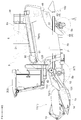
- the combine harvester threshs the crop cut by the reaper transport unit 1 for cutting the crop and transports it backward, the operation unit 3 covered with the cabin 2, and the reaper transport unit 1
- Threshing device 4 for performing the process
- a grain tank 5 for storing grains obtained by threshing with the threshing device 4
- a driving unit 6 having an engine 21 as a power source
- left and right traveling located on both sides of the machine Part 7
- the left and right traveling units 7 respectively have a front wheel 8 as a front traveling device that can not be steered and is rotationally driven, and a rear wheel 9 as a rear traveling device that can be steered.
- the longitudinal direction of the aircraft when defining the longitudinal direction of the aircraft, it is defined along the traveling direction of the aircraft in the working state, and when defining the left-right direction of the aircraft, the left and right are defined in the state viewed in the traveling direction of the aircraft.
- the direction shown by the code (F) in FIGS. 1, 2 and 3 is the front side of the machine
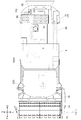
- the direction indicated by the symbol (L) in FIG. 3 is the left side of the machine
- the direction indicated by the symbol (R) in FIG. 3 is the right side of the machine.
- the reaper transport unit 1 is supported by a reaper elevating cylinder 10 as an elevating actuator at a front portion of the machine body so as to be driven to move up and down around a horizontal fulcrum P1.
- the reaper transport unit 1 reaps a crop to be planted and gathers the cropped crop at the central portion in the cutting width direction, and the cropped header 11 directs the crop cut and gathered at the central portion to the threshing device 4 at the rear of the aircraft.
- a feeder 12 for carrying.
- the reaper header 11 includes a rotating reel 13 that scrapes the tip side of the crop to be reaped toward the back, and a hair clipper type that cuts and reaps the plant origin of the crop.
- a cutting blade 14 and a transverse feed auger 15 or the like are provided to gather and collect the cropped crop in the central portion in the cutting width direction.
- the feeder 12 includes a drive sprocket 18 provided on a reaper input shaft 17 located at the rear upper portion and a driven rotating body 19 located at the front lower portion in a rectangular cylindrical transport case 16.
- a pair of left and right endless rotation chains 20 are wound and stretched all over.
- a locking transport body (not shown) is bridged at appropriate intervals along the circumferential direction over the left and right endless rotation chains 20, and the rotation transport of the endless rotation chain 20 enables the locking transport body. Is configured to transport the crop transferred from the reaper header 11 rearward and upward.
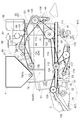
- the threshing device 4 is located at a low position in the center in the left-right direction of the machine, and the grain tank 5 is located on the front side of the machine above the threshing device 4 and the engine 21 as a power source is located on the rear side of the machine.
- the grain tank 5 and the engine 21 are arranged in the front-rear direction.
- Aircraft support structure The airframe support structure will be described. As shown in FIGS. 4 and 5, a pair of left and right main frames 22 extending in the longitudinal direction of the vehicle body, a front connecting portion 23 connecting the front of the left and right main frames 22, and a rear connecting the rear of the left and right main frames 22 An airframe frame 25 supporting the entire airframe is configured by the side connecting portion 24.
- the left and right main frames 22 are formed of a channel material having a substantially C-shaped cross section, and are long in the front-rear direction from the front to the rear of the vehicle, as shown in FIGS.
- the left and right traveling units 7, that is, the left and right front wheels 8 and the axles 8 a and 9 a of the left and right rear wheels 9 are provided at positions lower than the left and right main frames 22.
- the left and right front wheels 8 and the left and right rear wheels 9 are provided on the left and right sides of the left and right main frames 22 respectively in the left and right direction of the machine body. Are supported by the front wheels 8 and the left and right rear wheels 9.
- the front connecting portion 23 will be described. As shown in FIGS. 4 and 5, in the front side connecting portion 23, an upper horizontal portion connecting the left and right base portions 26 corresponding to the front projecting portions projecting forward from the left and right main frames 22 and the left and right base portions 26. A frame 27 and a lower horizontal frame 28 connecting the left and right side portions below the left and right base portions 26 are provided.
- the base portion 26 is integrally connected to the front end portions of the left and right main frames 22 so as to project forward.
- the upper horizontal frame 27 is in the form of a rectangular tube and extends over the left and right base portions 26, and the left and right sides are integrally connected to the base portion 26.
- an axle case 29 rotatably supporting an axle of the front wheel 8 is bolted to the lower surface side of the left and right base portions 26 projecting forward from the left and right main frames 22. There is. Therefore, the front side of the main frame 22 is supported by the front wheel 8.
- the left and right axle cases 29 are connected by the lower horizontal frame 28.
- the lower horizontal frame 28 includes left and right front-to-back connection members 30 extending in the front-rear direction, a rear side connection member 31 connecting the rear parts of the left and right front-to-back connection members 30, and front portions of the left and right front-to-back connection members 30. And a front side connector 32 connecting the two.
- a front side connection member 32 is bolted to the left and right axle cases 29.
- a transmission case 34 for mounting a traveling drive A (see FIG. 19) for traveling drive is provided so as to be inserted between the upper horizontal frame 27 and the lower horizontal frame 28. Then, as shown in FIG. 9, on the left and right sides of the transmission case, axle cases 29 for the front wheels 8 on the left and right, and relay transmission cases 35 on the left and right connecting the transmission case 34 and the axle cases 29 on the left and right are provided. It is done.
- the transmission case 34 and the relay transmission case 35 and the relay transmission case 35 and the axle case 29 are respectively flange-connected by bolt fastening. Accordingly, the axle case 29 of the left and right front wheels 8, the left and right relay transmission case 35, and the transmission case 34 are integrally connected.
- the rear lower portions of the left and right axle cases 29 are connected by a horizontal pipe frame 36 made of a round pipe material.
- a horizontal pipe frame 36 made of a round pipe material.
- an internal space is used as a reservoir of hydraulic oil.
- a front end portion of the transmission case 34 is connected to an intermediate portion in the left-right direction of the horizontal pipe frame 36 via a connecting member 37.
- the front connecting portion 23 constitutes a front portion connecting portion that connects the left and right traveling portions 7 (the front wheels 8).
- the rear connection portion 24 will be described. As shown in FIG. 5, the rear side connection portion 24 is provided with a rear connection body 38 made of a round pipe material located below the left and right main frames 22 and extending over the left and right main frames 22.
- a rear wheel support 39 as a traveling device support provided over the rear wheels is swingably supported by the rear connection body 38 around the longitudinal axis P2. That is, the rear wheel support 39 constitutes a rear traveling unit connecting body that connects the left and right traveling units 7 (rear wheels 9).
- the support frame 40 which protrudes downward is provided at the vehicle body rear side location in the main frame 22 on either side, and the rear connection body 38 is bridged and connected over the support frame 40 of the both right and left.
- the rolling support portion 41 is provided in a fixed state at the left and right middle portions of the rear connecting body 38, and the middle portion in the vehicle body width direction of the rear wheel support 39 in the vehicle body direction is swingable around the shaft center P2 in the vehicle front and rear direction. It is supported by the rolling support portion 41.
- the left and right rear wheels 9 are pivotally supported around the longitudinal axis center at the left and right side end portions of the rear wheel support 39, and a steering cylinder 42 is provided on the rear side of the rear wheel support 39 along the left and right direction. It is done.
- the rear wheel 9 can be pivoted about the longitudinal axis center by the operation of the steering cylinder 42.
- the threshing apparatus 4 includes a threshing unit 43 that performs a threshing process, and a sorting unit 44 that performs a sorting process on the processed material after the threshing process has been performed by the threshing unit 43.
- the threshing portion 43 is provided with a substantially box-like threshing frame 45 in a state of surrounding the outer peripheral portion, and the threshing barrel 46 that rotates around the rotation axis along the longitudinal direction of the machine is provided inside the threshing frame 45 At 46, the shredded grain of the reaping grain is processed.
- the sorting unit 44 is provided with a sorting unit frame 47 formed of a peripheral wall portion in a rectangular state, and grains and branches are swayed and transferred within the sorting unit frame 47 after the grain shedding processing has been performed.
- a sorting processing unit 48 (see FIGS. 8 and 19) is provided for sorting a second product such as a grain with a grain and waste scraps and the like.
- the threshing part 43 and the sorting part 44 are respectively constituted by the threshing frame 45 and the sorting part frame 47 as a frame structure having a large supporting strength at the outer peripheral part covering the periphery.
- a shredding device 49 is provided which shreds the threshing treatment material (waste straw scraps and the like) after the threshing treatment by the threshing device 4.
- the sorting processing unit 48 provided in the sorting unit 44 is a screw conveyor type that conveys grains that are leaked and sorted while swinging and transferring by the swinging sorting apparatus 50 to one side. It comprises a thing recovery device 51, a screw conveyor type second thing recovery device 52 for conveying the second thing to one side, and a blower 53 for supplying a sort of air to the processing object.
- a grain serving as a first thing conveying device for conveying the grain conveyed by the first thing recovery device 51 toward the upper grain tank 5
- a grain lifting conveyor 54 and a second reduction device 55 for reducing the second conveyed by the second collection device 52 to the threshing part 43 are provided.
- the threshing frame 45 which comprises the threshing part 43 is mounted and supported by the main frame 22 on either side.
- the threshing frame 45 extends substantially in the front-rear direction on both the left and right sides of the threshing part 43, and is substantially plate-shaped as a left-right vertical support extending along the vertical direction.
- a plurality of reinforcing supports and the like surrounding the peripheral portion of the wall portion are integrally connected.
- the front wall portion 58 and the rear wall portion 57 are formed with openings through which the threshing treatment passes.
- the reinforcing support is formed of a rectangular cylinder, an angle member, etc., and as a plurality of reinforcing supports, as shown in FIGS. 6 and 8, left and right lower portions extending in the front and rear direction along lower edges of the left and right side walls 56
- the threshing frame 45 is mounted on and supported by the left and right main frames 22.
- the lower supports 59 and the main frame 22 are connected by bolts at a plurality of locations. It is fixed.
- the left and right main frames 22 are provided in a horizontal state substantially parallel to the ground contact surface when the airframe is in contact with the ground, while the upper part of the threshing device 4 is , It is provided in a rear rising inclination state located on the upper side toward the rear side of the vehicle. That is, the left and right upper supports 60 are provided to be inclined upward and backward along the upper portion of the threshing device 4.
- the driving unit 3 is mounted and supported by a driving unit frame 62 connected and fixed to the threshing frame 45.
- the driver's frame 62 has its base end connected and fixed to the upper side of the left and right vertical frame 61, which is a reinforcing support at the front end of the threshing frame 45, and projects in a cantilever shape toward the front of the machine. It is provided in the state. Further, in the driver frame 62, rod-like left and right reinforcing members in which the middle part in the forward projecting direction is extended diagonally upward from the lower side location than the connection location of the base end in the left and right vertical frame 61 63 received and supported.
- the driving unit frame 62 is provided in a horizontal state so as to be substantially parallel to the ground contact surface.
- the driving unit 3 is surrounded by the cabin 2, and the entire driving unit 3 including the cabin 2 is configured by an integrated box-like body.
- Such an operation unit 3 is mounted on and supported by the operation unit frame 62 via a vibration isolation rubber (not shown) and fixed by bolt connection.
- the cutting and transportation is performed over the upper surface of the base portion 26 as a forward projecting portion protruding forward from the left and right main frames 22 and the front surface of the vertically facing frame 61 as shown in FIG.
- a bearing bracket 64 (see FIG. 6) for supporting the proximal end of the part 1 is received and supported.
- the base end portion is rotatably supported by the bearing bracket 64, and the whole of the reaper transport unit 1 is supported so as to be pivotable around the horizontal axis P1.
- a top plate 65 covering the upper side of the threshing cylinder 46 is curved in a substantially semi-cylindrical shape along the outer peripheral surface of the threshing cylinder 46.
- a threshing upper connection body 66 is provided at the upper side of the top plate 65 to connect the upper portions of the left and right side wall portions 56. As shown in FIGS. 7 and 8, a plurality of threshing upper connection bodies 66 are provided in a plurality in a state where they are appropriately spaced in the longitudinal direction of the machine body.
- the threshing upper connection body 66 is formed in an arc shape so that the lower end edge follows the shape of the top plate 65, and the lower end edge is bolt-connected as appropriate in a state where the lower end edge is in contact with the top plate 65. Thus, the threshing upper connection body 66 is supported by the top plate.
- the sorting unit frame 47 constituting the sorting unit 44 is suspended and supported by the left and right main frames 22.
- the sorting unit frame 47 has a side wall portion 67 covering the left and right sides of the sorting portion 44, and a front support portion 68 connecting the front sides of the left and right side wall portions 67. Is formed. Then, the upper end portions of the left and right side wall portions 67 are put on the lower surfaces of the left and right main frames 22, fixed by bolt connection, and suspended and supported.
- the front end of the sorting unit frame 47 and the front connecting portion 23 of the machine frame 25 are connected. Specifically, the rear horizontal connector 31 in the lower horizontal frame 28 of the front frame 23 of the airframe frame 25 and the front ends of the left and right side walls 67 of the sorting frame 47 are bolted together. It is done.
- the fuel tank 70 is provided between the front wheel 8 and the rear wheel on the left side, and in a state where the fuel tank 70 is located laterally outward of the sorting unit 44.
- a fuel tank support frame 71 for mounting and supporting the fuel tank 70 is provided.
- the fuel tank support frame 71 connects the left and right sides of the lower portion of the sorting unit frame 47, and protrudes outward to the left of the main frame 22 on the left side of the airframe of the left and right main frames 22. It is prepared in the state to do.
- the fuel tank support frame 71 has two laterally facing members 72 extending in the left and right direction separated from each other in the front and rear direction, and two front and rear facings connecting right side end portions of the two laterally facing members 72 and left and right middle portions.
- a member 73 and a tank mounting portion 74 provided at the left end of the two transverse members 72 are provided.
- the transverse member 72 is formed of a square pipe material, and the front and rear member 73 is formed of an angle member.
- a recessed portion 75 in which the laterally oriented member 72 is inserted is formed at a position corresponding to the front and rear laterally oriented members 72.
- the fuel tank support frame 71 is mounted from the lower side of the sorting unit frame 47 so that the front and rear laterally oriented members 72 enter the recessed portion 75, and the two front and rear facing members 73 are lower side with respect to the left and right side wall portions 67. It is bolted and fixed from.
- the tank mounting portion 74 protrudes outward to the left from the side wall portion 67 on the left side of the sorting portion frame 47, and the fuel tank 70 is mounted on and supported by the tank mounting portion 74.
- the grain tank 5 is provided above the threshing device 4 and positioned on the front side of the machine body.
- the grain tank 5 is supported on the top of the threshing frame 45. That is, the grain tank 5 is mounted on and supported by the upper supports 60 on the left and right in the threshing frame 45 via the front tank support frame 76 on the front side of the fuselage, and the rear side of the tank is a rear tank support frame 77. , And is mounted and supported on the left and right upper supports 60.
- the grain tank 5 is provided with a grain discharging device H for discharging the stored grain to the outside of the aircraft.
- a transverse feeding / conveying unit 78 located in the lower inside of the grain tank 5 and laterally feeding grains, and outside the grain tank 5, conveyed by the transverse feeding / conveying unit And a discharge conveyor 79 for conveying the kernels to the discharge point.
- the bottom of the grain tank 5 is formed to be tapered downward in the left-right direction, and the screw type is installed at the lower end of the downward tapered portion in the grain tank 5 as shown in FIGS.
- the transverse transport unit 78 is provided.
- the grain stored is configured to be guided downflow to the cross transport unit 78 at the time of discharge.
- a screw conveyor type discharge conveyor 79 for discharging the grain conveyed by the crossfeed conveyance unit 78 toward the discharge point outside the machine body is provided outside the left side of the grain tank 5. It is equipped.
- the grain tank 5 is formed in a downward tapered shape in the longitudinal direction of the machine body, and the discharge conveyor 79 is in a state in which the base end 80 is supported by the downward tapered slope portion of the grain tank 5 It is equipped.
- the proximal end 80 is rotatably supported around an axis perpendicular to the inclined surface.
- the discharge conveyor 79 is configured to be switchable between a projecting state in which the distal end portion projects outward and a stored state in which it retracts toward the inside of the machine by rotating the base end with the hydraulic cylinder 81. .
- the discharge conveyor 79 In the stored state, the discharge conveyor 79 is inclined upward from the rear side of the machine body as shown in FIG. 2 and, as shown in FIG. It is stored in a state of entering into the insertion portion 82.
- the fuel tank 70 is also housed in the state of entering the lower tapered recess 82 of the grain tank 5 similarly to the discharge conveyor 79.
- the grain tank 5 is supported by the front side tank support frame 76 on the front side in the lower-down inclined posture bottom side, and the rear side on the rear side in the upward-rising posture is the rear side tank support It is supported by a frame 77.
- the front side tank support frame 76 extends over the left and right side walls 56 of the threshing frame 45 and rests on the left and right upper supports 60 located at the upper edge of the left and right side walls 56. It is supported and bolted.
- the rear side tank support frame 77 like the front side tank support frame 76, extends over the left and right side walls 56 of the threshing frame 45 and is located on the upper edge of the left and right side walls 56. It is mounted and supported by
- the rear side tank support frame 77 includes left and right tank side support portions 83 located on the left and right sides, and a plurality of tank left and right tank side support portions 83 connected to each other.
- a connecting portion 84 is provided.
- the left and right tank side supports 83 are each formed in a substantially trapezoidal frame shape in a side view.
- the lower connecting member 84a connecting the lower portions of the left and right tank side support parts 83 among the tank left and right connecting parts 84 is formed in a round pipe shape.
- a rotary shaft for power transmission (counter shaft 138) is rotatably inserted and supported around the center axis in the left-right direction inside the lower connection member 84a.
- the left and right tank side support parts 83 are connected by a plurality of connecting members 84b in addition to the round pipe shaped tank left and right connection parts 84 to secure support strength.
- the driving unit 6 As shown in FIG. 15, the driving unit 6 is supported by the threshing frame 45 in a state of being located on the rear side of the grain tank 5. As shown in FIGS. 1 and 2, the drive unit 6 is covered with the drive unit cover 85 substantially throughout the outer periphery, but as shown in FIGS. 11 and 15 on the inward side of the drive unit cover 85.
- an exhaust treatment device 89 for purifying the exhaust gas from the engine 21.
- the exhaust treatment device 89 includes a diesel particulate filter (DPF) to reduce particulate matter (PM) such as diesel particulates contained in the exhaust gas.
- DPF diesel particulate filter
- PM particulate matter
- the driving unit cover 85 is configured to be easily opened for maintenance work.
- An engine support frame 91 for supporting the engine 21 is provided, and the engine support frame 91 extends over the left and right side walls 56 of the threshing frame 45 and is located at the upper edge of the left and right side walls 56 It is placed on and supported by the support 60.
- the engine support frame 91 includes side vertical surface portions 92 as left and right engine side support portions extending along the front and rear direction above the left and right upper supports 60, and left and right side portions.
- a front connecting member 93 as a front engine left and right connecting part connecting the front of the vertical surface 92 and a rear engine left connecting part connecting the front and rear middle parts of the left and right side vertical surface 92
- a rear support portion 95 for connecting the rear end portions of the left and right side vertical surface portions 92 with each other.
- a work table 96 on which a worker can get on for maintenance work of the drive unit 6, etc. is placed and supported.
- the left and right side vertical surface portions 92 are formed so that the front side of the machine body is wide in the vertical direction, and the width of the rear side of the machine body becomes substantially narrow. Lower end edges of the left and right side vertical surface portions 92 are bolted in a state of being mounted on the left and right upper supports 60.
- an engine mounting portion 97 for mounting and supporting the engine 21 is provided on both left and right sides.
- the engine 21 is mounted and supported by the four engine mounting portions 97 via a rubber mount.
- the rubber mount absorbs the vibration of the engine 21 so that the vibration is not transmitted to the operation unit 3.
- a protection fence 98 for protecting the worker is provided on the outer periphery of the work bench 96.
- the left and right upper supports 60 are provided in an upward-inclined inclined state positioned upward toward the rear of the machine, but the left and right side vertical surface portions 92 are formed so as to gradually narrow toward the rear of the machine. Therefore, the upper edges of the left and right side vertical surface portions 92 are in the horizontal state, and the engine mounting portion 97 and the work bench 96 are respectively provided in the horizontal state.
- the exhaust treatment device 89 and the radiator 88 are separately disposed on the left and right sides with respect to the engine 21 and the radiator 88 is disposed on the right side of the threshing device 4 (in It is provided in the state which protrudes outward on the right side from the edge part of (an example).
- the exhaust gas treatment device 89 is supported by the engine 21, and the radiator 88 is supported by the threshing device 4. As shown in FIG. 14, the exhaust treatment device 89 is mounted on and supported by a bearing member 99 fixed to the casing of the engine 21. The exhaust treatment device 89 and the engine 21 are provided side by side in the left-right direction with the upper end positions being substantially the same height.
- the radiator 88 is supported by a bracket 100 fixed to the right side wall 56 of the threshing frame 45.
- the cooling fan 90 is driven by a hydraulic motor.
- the drive unit 6 is provided with a support frame formed in a frame shape in order to support the drive unit cover 85. The lower end portion of the support frame is supported by the engine support frame 91. The upper portion of the radiator 88 is supported by the support frame and held in posture.
- an air cleaner 86 and a precleaner 87 are provided in a state where the air cleaner 86 and the precleaner 87 are located on the rear side of the engine 21.
- the air cleaner 86 and the precleaner 87 are supported by the engine support frame 91.
- the air cleaner 86 is supported by a support portion 101 located on the lower side and raised from the engine support frame 91.
- a work bench 96 is provided in a state where the air cleaner 86 and the precleaner 87 are located on the rear side of the machine, and maintenance work can be easily performed.
- a ladder 102 is provided at the rear of the work platform 96 for the operator to get on and off the work platform 96 from the outside of the machine body.
- Transmission structure 1 A transmission structure for transmitting the power of the engine 21 to the threshing device 4 and the reaper transport unit 1 will be described. As shown in FIG. 11, the engine 21 is provided in a state in which the output shaft 21A faces in the left-right direction and in a state in which the engine 21 protrudes leftward. As shown in FIG. 11, the engine 21 is provided in a state in which the output shaft 21A faces in the left-right direction and in a state in which the engine 21 protrudes leftward. As shown in FIG.
- a first transmission mechanism D1 (corresponding to a transmission mechanism for threshing drive) for transmitting the power of the engine 21 from the output shaft 21A to the threshing drum drive shaft 105 for driving the threshing drum;
- the power from the threshing drum drive shaft 105 is transmitted to the other driven devices provided in the sorting unit 44, that is, the swing sorting device 50, the first item recovery device 51, the second thing recovery device 52, and the blower 53
- a second transmission mechanism D2 is provided.
- the first transmission mechanism D1 and the second transmission mechanism D2 are disposed to be located on the left side of the engine 21 with respect to the engine 21.
- the throttling gearshift transmits the power transmitted to the threshing drum drive shaft 105 to the threshing drum at an upper side location of the shredding device 49 on the airframe rear side of the threshing device 4.
- a device 106 is provided.
- the threshing drum transmission 106 is surrounded by a case, and as shown in FIG. 19, the power transmitted from the threshing drum drive shaft 105, which is directed leftward and rightward, in the case is shifted up and down in two stages.
- a gear type transmission mechanism for transmitting to the threshing drum shaft 107 directed in the front-rear direction.
- the first transmission mechanism D1 is a belt type transmission mechanism that transmits power from the output shaft 21A of the engine 21 toward the threshing drum drive shaft 105.
- a transmission belt 110 is wound around an output pulley 108 provided on the output shaft 21A and an input pulley 109 provided on the threshing drum drive shaft 105.
- the first transmission mechanism D1 is positioned on the left side of the threshing device 4 and is provided in a slanting back and down state so as to be positioned lower toward the rear side of the machine body, and transmits power toward the lower back side.
- the second transmission mechanism D2 is a threshing input shaft 111 to which power from the threshing drum drive shaft 105 is input and a threshing relay to which power from the threshing input shaft 111 is transmitted. And a shaft 112, and transmits the power from the threshing input shaft 111 to the swing sorting device 50, and the power from the threshing relay shaft 112 is a first item recovery device 51, a second thing recovery device 52, And, it is configured to transmit to the blower 53.
- the second transmission mechanism D 2 includes a belt-type first threshing transmission mechanism 113 that transmits power from the threshing drum drive shaft 105 to the threshing input shaft 111, and a relay shaft 112 for threshing from the threshing input shaft 111.
- a transmission mechanism 117 and a chain transmission mechanism 118 for transmitting power from the threshing input shaft 111 to the swing sorting device 50 (specifically, a swing drive unit) are provided.
- the threshing drum drive shaft 105 is provided at a high position at the rear of the threshing part 43, and the threshing input shaft 111 is on the front side of the fuselage drive shaft 105 and in the lower part of the threshing part 43. It is provided in the state of being located.
- the first threshing transmission mechanism 113 is provided in a forward-down inclined state.
- the second threshing transmission mechanism 114 is provided to extend forward from the threshing input shaft 111 in a substantially horizontal position. Therefore, the first threshing power transmission mechanism 113 and the second threshing power transmission mechanism 114 are disposed in a state of being bent in a substantially L shape projecting downward.
- the fifth threshing transmission mechanism 117 is provided with a blower transmission mechanism 119 formed of a split pulley type belt continuously variable transmission.
- the blower transmission mechanism 119 changes the belt winding diameter by changing the distance between the split pulleys 121 by the cam mechanism 120 incorporated as shown in FIG. it can.
- the operation of the cam mechanism 120 is performed by a manual operation or an operation by an actuator.
- the power transmitted to the first item recovery device 51 is transmitted to the grain lifting conveyor 54. Also, the power transmitted to the second product recovery device 52 is transmitted to the second product reduction device 55.
- a power input pulley 122 as a power input rotary body in which power from the threshing drum drive shaft 105 is input to the threshing input shaft 111 sequentially from the lateral side of the machine, relay for threshing
- the relay pulley 123 as a relay output rotator outputting power to the shaft 112
- the output sprocket 118A as a sorting output rotator in the chain transmission mechanism 118 outputting power to the swing sorting device 50 In the state, they are supported integrally rotatably.
- the relay input pulley 124 as a relay input rotating body to which power from the threshing input shaft 111 is transmitted to the threshing relay shaft 112 sequentially from the lateral side of the machine, the reaper transport section 1.
- An output pulley 125 for cutting and conveying as an output rotating body for cutting and conveying that outputs a power to 1 and a pulley 126 for selecting output as an output rotating body for selecting and outputting a power to a first object recovery device 51 Is supported integrally rotatably.
- a belt type reaping transmission mechanism 127 as a third transmission mechanism D3 for transmitting the power transmitted to the sorting processing unit 48 to the reaper transport unit 1 is provided.
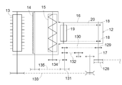
- the reaper transmission mechanism 127 is configured to transmit the power from the threshing relay shaft 112 to the reaper input shaft 17 of the reaper transport unit 1.
- the reaper input shaft 17 functions as a drive shaft of the feeder 12 and is provided in a state of projecting outward from the transport case 16 of the feeder 12 to the left.
- the cutting power transmission mechanism 127 is provided to extend forward from the relaying shaft 112 for threshing in a substantially horizontal posture.
- the reap-and-transfer input pulley 128 as a reap-transfer input rotary member to which power from the threshing relay shaft 112 is transmitted protrudes leftward outward from the transfer case 16 in the reaping input shaft 17. It is integrally rotatably supported by the outward protrusion. Then, among the outwardly projecting portions of the reaper input shaft 17, the rotary reel 13, the cutting blade 14, and the cross feed auger are located at a position located between the reaper transfer input pulley 128 and the feeder 12 (the transfer case 16). A reaping output sprocket 129 as a reaping output rotator that outputs power to 15 is supported integrally rotatably.
- the power from the reaper output sprocket 129 is a reaper relay provided at the rear of the reaper header 11 by a transmission chain 130 extending in the front-rear direction along the left outside of the transfer case 16
- the shaft 131 is transmitted.
- the power from the reaper relay shaft 131 is transmitted to the rotating reel 13 via the reel chain transmission mechanism 132 and the belt transmission mechanism 133, and is transmitted to the crossfeed auger 15 via the auger chain transmission mechanism 134 for cutting blades. It is transmitted to the cutting blade 14 through the belt transmission mechanism 135.
- a belt-type shredding transmission mechanism 136 for transmitting the power from the threshing drum drive shaft 105 to the shredding apparatus 49 is provided.
- the shredding processing transmission mechanism 139 is provided to extend downward from the threshing cylinder drive shaft 105. Therefore, the second transmission mechanism D2 is configured to branch and transmit the power transmitted to the threshing drum drive shaft 105 to the sorting processing unit 48 and the shredding device 49.
- the threshing power transmission system for transmitting the power from the threshing drum drive shaft 105 to the plurality of driven devices provided in the sorting processing unit 48 is collectively provided on the left side of the threshing device 4 ing.
- a power transmission system for cutting that transmits the power from the cutting input shaft 17 to the rotating reel 13, the cutting blade 14, and the cross feed auger 15 is collectively provided on the left side of the cutting conveyance unit 1. Therefore, the power transmission unit for transmitting the power from the output shaft 21A of the engine 21 to the plurality of driven devices provided in the sorting processing unit 48 is disposed on the left side of the engine 21 (an example on one side in the left-right direction). Ru.
- a fourth transmission mechanism D4 for transmitting the power from the engine 21 to the grain discharging device H and the traveling drive A is provided, and on the output shaft 21A of the engine 21, the power of the engine 21 is It branches into a first transmission mechanism D1 and a fourth transmission mechanism D4.
- the counter shaft 138 as a first relay shaft to which power is transmitted from the output shaft 21A of the engine 21 through the transmission belt 137 is provided, and the power of the engine 21 is the right end of the counter shaft 138 Are branched and transmitted to the grain discharging device H and the traveling drive device A. Therefore, the power transmission unit for transmitting the power from the output shaft 21A of the engine 21 to the grain discharging device H and the traveling drive device A is disposed on the right side of the engine 21 with respect to the engine 21.
- the counter shaft 138 which is a rotating shaft for transmission, extends from a lateral portion of the threshing device 4 to the other side in a state of passing through the inside of the round pipe-shaped lower connecting member 84a in the rear side tank support frame 77. It extends and is rotatably supported about a left-right facing axial center. That is, it is provided extending from the left side of the machine body to the right side of the machine as one side in the left-right direction of the machine, and the power from the output shaft 21A is input to the left side of the machine, and the grain discharging device H and travel are
- the driving device A is configured to output power.
- the countershaft 138 is provided in an area surrounded by the upper surface of the threshing device 4 and the grain tank 5 and the engine 21 in a side view.
- a belt-type discharge transmission mechanism 139 for transmitting the power from the counter shaft 138 to the cross feed transport portion 78 of the grain discharging device H, and the threshing portion from the power from the counter shaft 138
- the belt drive type first transmission mechanism 141 for transmitting to the traveling relay shaft 140 as a second relay shaft provided on the front side of the front portion 43 and the power from the traveling relay shaft 140 to the traveling drive device A
- a belt type traveling second transmission mechanism 142 for transmitting is provided.
- the discharge transmission mechanism 139 is provided to extend forward in a substantially horizontal posture.
- the power transmitted from the discharge transmission mechanism 139 is configured to be transmitted to the discharge conveyor 79 located on the left side of the machine body via the cross feed conveyance unit 78.
- the first traveling transmission mechanism 141 is provided to extend from the counter shaft 138 in a forward and downward direction in an inclined posture.
- the traveling drive device A is provided at a lower position of the grain tank 5 in the lower part of the machine body, and the second traveling transmission mechanism 142 is provided to extend downward from the traveling relay shaft 140 in a substantially vertical posture. ing.
- the traveling drive device A does not describe the detailed configuration, but based on the driving operation of the shift operation tool, the turning operation tool, etc. (not shown) provided in the driving unit 3, the driving operation of the left and right front wheels 8 is performed. It is configured to transmit power to drive at a suitable speed. When going straight on, the left and right front wheels 8 are at the same speed or substantially the same speed, and when turning, they are driven with a speed difference.
- the output shaft 21A of the engine 21 is provided at the left side of the machine, and the power transmission unit for transmitting power from each output shaft 21A to the devices of the threshing device 4 and the reaper transport unit 1 is disposed on the left side of the machine There is.
- the countershaft 138 is configured to output power to the grain discharging device H and the traveling drive A from the right side of the machine body. That is, a power transmission unit for transmitting power from the output shaft 21A to the grain discharging device H and the traveling driving device A is disposed on the right side of the machine. Then, the power transmitted from the counter shaft 138 from the right side of the machine is transmitted to the discharge conveyor 79 located on the left side of the machine via the cross feed conveyance unit 78.
- the grain tank 5 is located on the front side of the machine above the threshing device 4, and the engine 21 is located on the rear side of the machine, so that the grain tank 5 and the engine 21 are back and forth.
- the configuration is such that they are arranged in the direction, the engine 21 is located on the front side of the machine above the threshing device 4 and the grain tank 5 is located on the rear side of the machine instead of this configuration.
- only the grain tank 5 may be disposed above the threshing device 4 or only the engine 21 may be disposed above the threshing device 4. May be Alternatively, the grain tank 5 and the engine 21 may be disposed at the side or rear side of the threshing device 4.
- the substantially plate-like side wall portion 56 is provided as the left and right vertical support portions of the threshing frame 45, but instead of this structure, a wall covering the side of the threshing portion Alternatively, a dedicated frame member may be erected from the main frame, and the configuration of the threshing frame can be implemented with various changes.
- the front traveling unit coupling body is configured by the front side coupling unit 23 including the base portion 26, the upper horizontal frame 27, and the lower horizontal frame 28, and the rear traveling unit coupling body
- the rear wheel support body 39 replaces with this structure and employ
- a configuration similar to that of the rear wheel support 39 may be adopted.
- the front side of the left and right main frames 22 is connected by the front side connecting portion 23, and the rear side of the left and right main frames 22 is configured by the rear side connecting portion 24.
- the rear side of the left and right main frames 22 is connected by a connecting portion similar to the front side connecting portion 23, and the left and right main frames 22 are connected by a connecting portion similar to the rear side connecting portion 24.
- the threshing upper connection body 66 connecting the upper portions of the left and right vertical support portions is provided, and the threshing upper connection body 66 is connected to the top plate 65 of the threshing device 4.
- the threshing upper connection body 66 may not be connected to the top plate 65 of the threshing device 4.
- the transmission case 34 is provided to be inserted between the upper horizontal frame 27 and the lower horizontal frame 28.
- the transmission case 34 includes the upper horizontal frame 27 and the lower horizontal frame 28.
- the configuration may be such that a portion protrudes outward from the region between the two.
- the base end of the reaper transport unit 1 is supported over the upper surfaces of the left and right base portions 26 and the front surface of the vertically oriented frame body of the threshing frame 45.
- the base end of the reaper transport unit 1 may be supported by the left and right main frames 22 at a location apart from the vertically oriented frame body of the threshing frame 45.
- the exhaust treatment device 89 and the radiator 88 are separately disposed on the left and right sides with respect to the engine 21 in the longitudinal direction of the airframe, but instead of this configuration, the exhaust treatment device It may be configured to be provided above the engine.
- the traveling unit includes the front wheel 8 as the front traveling device and the rear wheel 9 as the rear traveling device.
- the front traveling device and the rear One of the side traveling devices may be constituted by the crawler traveling device and the other may be constituted by the wheels, or the front traveling device and the rear traveling device may be respectively constituted by the crawler traveling device.
- the left and right traveling units may be configured by one crawler traveling device.
- the present invention can also be applied to self-release type combine that threshs the tip side while holding and conveying the stock origin of the mowing grain gutter with a feed chain, in addition to the ordinary type combine.
Landscapes
- Life Sciences & Earth Sciences (AREA)
- Environmental Sciences (AREA)
- Harvester Elements (AREA)
- Combines (AREA)
Abstract
L'invention concerne une moissonneuse-batteuse qui comprend des structures principales gauche et droite 22 qui s'étendent dans la direction longitudinale d'un corps de machine, et un dispositif de battage 4 installé entre les structures principales gauche et droite 22. Le dispositif de battage 4 comprend une unité de battage 43 qui met en œuvre un processus de retrait des grains, et une unité de sélection 44 située au-dessous de l'unité de battage 43, l'unité de sélection 44 mettant en œuvre un processus de sélection d'articles traités après que le processus de retrait des grains ait été assuré par l'unité de battage 43. Une structure de battage 45 qui constitue l'unité de battage 43 est installée dans et supportée par les structures principales gauche et droite 22, et une structure d'unité de sélection 47 qui constitue l'unité de sélection est suspendue sur et supportée par les structures principales gauche et droite 22.
Priority Applications (5)
| Application Number | Priority Date | Filing Date | Title |
|---|---|---|---|
| EP17929621.5A EP3701786A4 (fr) | 2017-10-25 | 2017-10-25 | Moissonneuse-batteuse |
| US16/757,857 US11559001B2 (en) | 2017-10-25 | 2017-10-25 | Combine harvester frame arrangement |
| JP2019549744A JP6887519B2 (ja) | 2017-10-25 | 2017-10-25 | コンバイン |
| PCT/JP2017/038544 WO2019082305A1 (fr) | 2017-10-25 | 2017-10-25 | Moissonneuse-batteuse |
| CN201780096309.7A CN111278273A (zh) | 2017-10-25 | 2017-10-25 | 联合收割机 |
Applications Claiming Priority (1)
| Application Number | Priority Date | Filing Date | Title |
|---|---|---|---|
| PCT/JP2017/038544 WO2019082305A1 (fr) | 2017-10-25 | 2017-10-25 | Moissonneuse-batteuse |
Publications (1)
| Publication Number | Publication Date |
|---|---|
| WO2019082305A1 true WO2019082305A1 (fr) | 2019-05-02 |
Family
ID=66246288
Family Applications (1)
| Application Number | Title | Priority Date | Filing Date |
|---|---|---|---|
| PCT/JP2017/038544 Ceased WO2019082305A1 (fr) | 2017-10-25 | 2017-10-25 | Moissonneuse-batteuse |
Country Status (5)
| Country | Link |
|---|---|
| US (1) | US11559001B2 (fr) |
| EP (1) | EP3701786A4 (fr) |
| JP (1) | JP6887519B2 (fr) |
| CN (1) | CN111278273A (fr) |
| WO (1) | WO2019082305A1 (fr) |
Citations (5)
| Publication number | Priority date | Publication date | Assignee | Title |
|---|---|---|---|---|
| JP2010187696A (ja) * | 2010-04-27 | 2010-09-02 | Iseki & Co Ltd | 脱穀機 |
| JP2014014323A (ja) | 2012-07-10 | 2014-01-30 | Kubota Corp | コンバイン |
| JP2015142514A (ja) * | 2014-01-31 | 2015-08-06 | 井関農機株式会社 | コンバイン |
| JP2016049093A (ja) * | 2014-09-02 | 2016-04-11 | 株式会社クボタ | コンバイン |
| JP2017121224A (ja) * | 2016-01-08 | 2017-07-13 | ヤンマー株式会社 | コンバイン |
Family Cites Families (20)
| Publication number | Priority date | Publication date | Assignee | Title |
|---|---|---|---|---|
| BE788802A (nl) * | 1971-07-06 | 1973-01-02 | Clayson Nv | Verbeteringen aan maaidorsers. |
| US3760813A (en) * | 1971-12-09 | 1973-09-25 | B Mathews | Combine with grain bin beneath sieves |
| DE2443915A1 (de) * | 1974-09-13 | 1976-04-01 | Ernst Weichel | Motor-landmaschine |
| GB1544188A (en) * | 1976-05-11 | 1979-04-11 | Clayson Nv | Combine harvesters |
| DE3674001D1 (de) | 1986-07-01 | 1990-10-11 | Ford New Holland Inc | Maehdrescher. |
| DE3917605A1 (de) * | 1989-05-31 | 1990-12-06 | Claas Ohg | Maehdrescher |
| US5290201A (en) * | 1992-06-11 | 1994-03-01 | Tesker Henry L | Combine with mmoveable body and tandem drive wheels |
| US5437145A (en) * | 1993-08-19 | 1995-08-01 | Case Corporation | Feeder assembly coupling structure for an agricultural harvester |
| US5475972A (en) * | 1994-06-30 | 1995-12-19 | Deere & Company | Tank structure for a harvester and method of assembly |
| US5499948A (en) * | 1994-09-01 | 1996-03-19 | Deere & Company | Modular threshing assembly for a combine |
| US6267198B1 (en) * | 1999-12-23 | 2001-07-31 | New Holland North America, Inc. | Offset kingpin for a rear steering axle on an agricultural combine |
| US6421993B1 (en) * | 2001-02-28 | 2002-07-23 | Deere & Company | Multi-piece feederhouse bushing retainer |
| US7670219B2 (en) * | 2006-12-13 | 2010-03-02 | Cnh America Llc | Integrated axle and cleaning fan wrapper for an agricultural harvesting machine |
| JP2011015637A (ja) * | 2009-07-08 | 2011-01-27 | Yanmar Co Ltd | コンバイン |
| JP5573463B2 (ja) * | 2010-07-30 | 2014-08-20 | 井関農機株式会社 | 脱穀装置 |
| CN107396682B (zh) * | 2012-02-01 | 2021-07-13 | 株式会社久保田 | 割取收获机 |
| CN109964622A (zh) * | 2013-08-07 | 2019-07-05 | 株式会社久保田 | 联合收割机和收割机 |
| US10375884B2 (en) * | 2015-08-18 | 2019-08-13 | Agco Corporation | Self-propelled harvester with front access to crop processing apparatus |
| US10426089B2 (en) * | 2016-07-06 | 2019-10-01 | Tribine Industries Llc | Feeder having lateral tilt for an agricultural harvesting combine |
| US10667453B2 (en) * | 2018-02-22 | 2020-06-02 | Indústrias Reunidas Colombo Ltda | Agricultural motor vehicle |
-
2017
- 2017-10-25 WO PCT/JP2017/038544 patent/WO2019082305A1/fr not_active Ceased
- 2017-10-25 US US16/757,857 patent/US11559001B2/en active Active
- 2017-10-25 EP EP17929621.5A patent/EP3701786A4/fr active Pending
- 2017-10-25 JP JP2019549744A patent/JP6887519B2/ja not_active Expired - Fee Related
- 2017-10-25 CN CN201780096309.7A patent/CN111278273A/zh active Pending
Patent Citations (5)
| Publication number | Priority date | Publication date | Assignee | Title |
|---|---|---|---|---|
| JP2010187696A (ja) * | 2010-04-27 | 2010-09-02 | Iseki & Co Ltd | 脱穀機 |
| JP2014014323A (ja) | 2012-07-10 | 2014-01-30 | Kubota Corp | コンバイン |
| JP2015142514A (ja) * | 2014-01-31 | 2015-08-06 | 井関農機株式会社 | コンバイン |
| JP2016049093A (ja) * | 2014-09-02 | 2016-04-11 | 株式会社クボタ | コンバイン |
| JP2017121224A (ja) * | 2016-01-08 | 2017-07-13 | ヤンマー株式会社 | コンバイン |
Non-Patent Citations (1)
| Title |
|---|
| See also references of EP3701786A4 |
Also Published As
| Publication number | Publication date |
|---|---|
| EP3701786A4 (fr) | 2021-06-23 |
| EP3701786A1 (fr) | 2020-09-02 |
| CN111278273A (zh) | 2020-06-12 |
| US20210185931A1 (en) | 2021-06-24 |
| JP6887519B2 (ja) | 2021-06-16 |
| US11559001B2 (en) | 2023-01-24 |
| JPWO2019082305A1 (ja) | 2020-10-22 |
Similar Documents
| Publication | Publication Date | Title |
|---|---|---|
| JP7004735B2 (ja) | コンバイン | |
| JP2019076034A (ja) | 収穫機 | |
| JP5828581B2 (ja) | 普通型コンバイン | |
| CN109475086B (zh) | 甘蔗收割机 | |
| JP5271011B2 (ja) | コンバイン | |
| JP5436378B2 (ja) | コンバイン | |
| JP2010200710A (ja) | コンバイン | |
| JP6765348B2 (ja) | コンバイン | |
| WO2012111233A1 (fr) | Moissonneuse de type classique | |
| JP6104202B2 (ja) | コンバイン | |
| JP6887519B2 (ja) | コンバイン | |
| WO2019082307A1 (fr) | Moissonneuse-batteuse | |
| JP7190382B2 (ja) | コンバイン | |
| WO2019082306A1 (fr) | Moissonneuse-batteuse | |
| CN100420365C (zh) | 联合收割机 | |
| JP5991231B2 (ja) | コンバイン | |
| JP2021023130A (ja) | コンバイン | |
| JP7262349B2 (ja) | サトウキビ収穫機 | |
| JP7321037B2 (ja) | サトウキビ収穫機 | |
| JP2019154259A (ja) | 収穫機 | |
| CN115529931A (zh) | 割取装置以及收割机 | |
| JP2016036263A (ja) | 収穫機 | |
| JP2024005012A (ja) | コンバイン | |
| JP2022070660A (ja) | コンバイン | |
| JP2014209890A (ja) | トウモロコシ収穫機 |
Legal Events
| Date | Code | Title | Description |
|---|---|---|---|
| 121 | Ep: the epo has been informed by wipo that ep was designated in this application |
Ref document number: 17929621 Country of ref document: EP Kind code of ref document: A1 |
|
| ENP | Entry into the national phase |
Ref document number: 2019549744 Country of ref document: JP Kind code of ref document: A |
|
| NENP | Non-entry into the national phase |
Ref country code: DE |
|
| ENP | Entry into the national phase |
Ref document number: 2017929621 Country of ref document: EP Effective date: 20200525 |