WO2019082368A1 - Terminal utilisateur et procédé de communication radio - Google Patents
Terminal utilisateur et procédé de communication radioInfo
- Publication number
- WO2019082368A1 WO2019082368A1 PCT/JP2017/038814 JP2017038814W WO2019082368A1 WO 2019082368 A1 WO2019082368 A1 WO 2019082368A1 JP 2017038814 W JP2017038814 W JP 2017038814W WO 2019082368 A1 WO2019082368 A1 WO 2019082368A1
- Authority
- WO
- WIPO (PCT)
- Prior art keywords
- pdcch
- bwp
- unit
- control
- signal
- Prior art date
- Legal status (The legal status is an assumption and is not a legal conclusion. Google has not performed a legal analysis and makes no representation as to the accuracy of the status listed.)
- Ceased
Links
Images







Classifications
-
- H—ELECTRICITY
- H04—ELECTRIC COMMUNICATION TECHNIQUE
- H04L—TRANSMISSION OF DIGITAL INFORMATION, e.g. TELEGRAPHIC COMMUNICATION
- H04L5/00—Arrangements affording multiple use of the transmission path
- H04L5/003—Arrangements for allocating sub-channels of the transmission path
- H04L5/0053—Allocation of signalling, i.e. of overhead other than pilot signals
-
- H—ELECTRICITY
- H04—ELECTRIC COMMUNICATION TECHNIQUE
- H04L—TRANSMISSION OF DIGITAL INFORMATION, e.g. TELEGRAPHIC COMMUNICATION
- H04L27/00—Modulated-carrier systems
- H04L27/26—Systems using multi-frequency codes
- H04L27/2601—Multicarrier modulation systems
- H04L27/2602—Signal structure
- H04L27/26025—Numerology, i.e. varying one or more of symbol duration, subcarrier spacing, Fourier transform size, sampling rate or down-clocking
-
- H—ELECTRICITY
- H04—ELECTRIC COMMUNICATION TECHNIQUE
- H04L—TRANSMISSION OF DIGITAL INFORMATION, e.g. TELEGRAPHIC COMMUNICATION
- H04L5/00—Arrangements affording multiple use of the transmission path
- H04L5/0091—Signalling for the administration of the divided path, e.g. signalling of configuration information
- H04L5/0094—Indication of how sub-channels of the path are allocated
-
- H—ELECTRICITY
- H04—ELECTRIC COMMUNICATION TECHNIQUE
- H04W—WIRELESS COMMUNICATION NETWORKS
- H04W52/00—Power management, e.g. Transmission Power Control [TPC] or power classes
- H04W52/02—Power saving arrangements
- H04W52/0209—Power saving arrangements in terminal devices
- H04W52/0212—Power saving arrangements in terminal devices managed by the network, e.g. network or access point is leader and terminal is follower
- H04W52/0216—Power saving arrangements in terminal devices managed by the network, e.g. network or access point is leader and terminal is follower using a pre-established activity schedule, e.g. traffic indication frame
-
- H—ELECTRICITY
- H04—ELECTRIC COMMUNICATION TECHNIQUE
- H04W—WIRELESS COMMUNICATION NETWORKS
- H04W52/00—Power management, e.g. Transmission Power Control [TPC] or power classes
- H04W52/02—Power saving arrangements
- H04W52/0209—Power saving arrangements in terminal devices
- H04W52/0225—Power saving arrangements in terminal devices using monitoring of external events, e.g. the presence of a signal
- H04W52/0229—Power saving arrangements in terminal devices using monitoring of external events, e.g. the presence of a signal where the received signal is a wanted signal
-
- H—ELECTRICITY
- H04—ELECTRIC COMMUNICATION TECHNIQUE
- H04W—WIRELESS COMMUNICATION NETWORKS
- H04W72/00—Local resource management
- H04W72/04—Wireless resource allocation
- H04W72/044—Wireless resource allocation based on the type of the allocated resource
- H04W72/0453—Resources in frequency domain, e.g. a carrier in FDMA
-
- H—ELECTRICITY
- H04—ELECTRIC COMMUNICATION TECHNIQUE
- H04W—WIRELESS COMMUNICATION NETWORKS
- H04W72/00—Local resource management
- H04W72/20—Control channels or signalling for resource management
- H04W72/23—Control channels or signalling for resource management in the downlink direction of a wireless link, i.e. towards a terminal
-
- Y—GENERAL TAGGING OF NEW TECHNOLOGICAL DEVELOPMENTS; GENERAL TAGGING OF CROSS-SECTIONAL TECHNOLOGIES SPANNING OVER SEVERAL SECTIONS OF THE IPC; TECHNICAL SUBJECTS COVERED BY FORMER USPC CROSS-REFERENCE ART COLLECTIONS [XRACs] AND DIGESTS
- Y02—TECHNOLOGIES OR APPLICATIONS FOR MITIGATION OR ADAPTATION AGAINST CLIMATE CHANGE
- Y02D—CLIMATE CHANGE MITIGATION TECHNOLOGIES IN INFORMATION AND COMMUNICATION TECHNOLOGIES [ICT], I.E. INFORMATION AND COMMUNICATION TECHNOLOGIES AIMING AT THE REDUCTION OF THEIR OWN ENERGY USE
- Y02D30/00—Reducing energy consumption in communication networks
- Y02D30/70—Reducing energy consumption in communication networks in wireless communication networks
Definitions
- the present disclosure relates to a user terminal and a wireless communication method in a next-generation mobile communication system.
- LTE Long Term Evolution
- Non-Patent Document 1 LTE Advanced, LTE Rel. 10, 11, 12, 13
- LTE Rel. 8, 9 LTE Rel. 8, 9
- LTE successor system for example, FRA (Future Radio Access), 5G (5th generation mobile communication system), 5G + (plus), NR (New Radio), NX (New radio access), FX (Future generation radio access), LTE Also referred to as Rel. 14 or 15).
- a base station controls allocation (scheduling) of data to a user terminal (UE: User Equipment).
- the base station notifies the UE of downlink control information (DCI: Downlink Control Information) indicating a data scheduling instruction using a downlink control channel (for example, PDCCH (Physical Downlink Control Channel)).
- DCI Downlink Control Information
- PDCCH Physical Downlink Control Channel
- E-UTRA Evolved Universal Terrestrial Radio Access
- E-UTRAN Evolved Universal Terrestrial Radio Access Network
- CC Component Carrier
- BWP bandwidth part
- cross BWP / cross carrier control such as controlling another BWP using PDCCH notified in one BWP, controlling another CC using PDCCH notified in one CC, etc. It is being considered.
- the present disclosure has an object to provide a user terminal and a wireless communication method capable of appropriately determining the monitoring cycle of the downlink control channel even when a plurality of the numerologies are used.
- a user terminal is a receiver that monitors a downlink control channel for control on another frequency resource in a predetermined frequency resource, and a downlink control channel for control on the predetermined frequency resource. And a controller configured to determine a monitoring cycle of the downlink control channel for control in the other frequency resource based on the monitoring cycle.
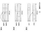
- FIGS. 1A-1C are diagrams showing an example of notifying SFI using GC-PDCCH.
- FIGS. 2A-2C are diagrams showing an example of notifying SFI using a normal PDCCH.
- FIGS. 3A and 3B are diagrams showing an example of cross-BWP and cross-carrier GC-PDCCH monitoring, respectively.
- FIG. 4 is a diagram showing an example of a PDCCH monitoring period in the first embodiment.
- FIG. 5 is a diagram illustrating another example of the PDCCH monitoring period in the first embodiment.
- FIG. 6 is a diagram illustrating an example of a monitoring cycle supported by the UE.
- FIG. 7 is a diagram showing an example of the correspondence between the terminology and the monitoring period.
- FIG. 8 is a diagram illustrating an example of a PDCCH monitoring period in the second embodiment.
- FIG. 9 is a diagram illustrating another example of the PDCCH monitoring period in the second embodiment.
- FIG. 10 is a diagram showing an example of a schematic configuration of a wireless communication system according to an embodiment.
- FIG. 11 is a diagram illustrating an example of the entire configuration of the radio base station according to an embodiment.
- FIG. 12 is a diagram illustrating an example of a functional configuration of a wireless base station according to an embodiment.
- FIG. 13 is a diagram showing an example of the entire configuration of a user terminal according to an embodiment.
- FIG. 14 is a diagram illustrating an example of a functional configuration of a user terminal according to an embodiment.
- FIG. 15 is a diagram illustrating an example of a hardware configuration of a wireless base station and a user terminal according to an embodiment.
- a downlink control channel for transmitting downlink control information (DCI: Downlink Control Information) is considered.
- DCI Downlink Control Information
- the UE monitors downlink control information by monitoring (may be referred to as blind decoding) one or more control resource sets (CORESET) set in the UE.
- CORESET control resource sets
- DCI that schedules DL data e.g., Physical Downlink Shared Channel (PDSCH)
- DL assignment e.g., Physical Downlink Shared Channel (PDSCH)
- DL DCI DL assignment
- DL grant DL DCI
- DL DCI for scheduling transmission of UL data for example, PUSCH: Physical Uplink Shared Channel (PUSCH)
- PUSCH Physical Uplink Shared Channel
- UL sounding (for measurement) signals may be referred to as UL grant, UL DCI, and so on.
- PDCCH common to one or more UEs group common PDCCH (GC ⁇ ) other than PDCCH for one UE (may be called UE-specific PDCCH, usually PDCCH, etc.)
- UE group common PDCCH UE group common PDCCH, etc.
- the “normal PDCCH” may represent a PDCCH that transmits DCI for scheduling PDSCH and / or PUSCH.
- the “normal PDCCH” may represent a PDCCH that transmits DCI that triggers measurement, reporting, and the like of A-SRS (Aperiodic Sounding Reference Signal) and / or A-CSI (Aperiodic Channel State Information).
- the “ordinary PDCCH” may represent a PDCCH that transmits DCI that controls (activates, releases) SPS (Semi-Persistent Scheduling), UL grant free transmission and / or SP-CSI (Semi-Persistent CSI).
- the DCI transmitted by GC-PDCCH may be called a group common DCI.
- the GC-PDCCH and the normal PDCCH may be assigned to the leading symbols (eg, the first 1, 2 or 3 symbols) of the slot. Note that the position to which the PDCCH is assigned is not limited to this.
- BWP bandwidth parts
- CC component carrier
- the BWP is associated with a specific neurology (sub-carrier spacing (SCS: Sub-Carrier Spacing, cyclic prefix length, etc.)).
- SCS Sub-Carrier Spacing, cyclic prefix length, etc.
- the UE receives in the active DL BWP (BWP used for DL communication) using the terminology related to the DL BWP, and in the active UL BWP (BWP used for UL communication) , Transmit using the neurology associated with the UL BWP.
- the UE may perform BWP configuration information (which may be called BWP configuration (configuration)) as a base station (for example, BS (Base Station), transmission / reception point (TRP: Transmission / Reception Point), eNB (eNode B), It may be received from gNB or the like.
- BWP configuration configuration (configuration)
- BS Base Station
- TRP Transmission / Reception Point
- eNB eNode B
- It may be received from gNB or the like.
- the BWP setting includes B / W's merology, frequency position (for example, center frequency), bandwidth (for example, number of resource blocks (also called RB (Resource Block), PRB (Physical RB), etc.), time resources (for example, , Slot (minislot) index, period), etc. may be included.
- the BWP configuration may be notified (configured) to the UE, for example, by higher layer signaling, physical layer signaling or a combination thereof.
- upper layer signaling may be, for example, RRC (Radio Resource Control) signaling, MAC (Medium Access Control) signaling (eg MAC control element (MAC CE (Control Element)), MAC PDU (Protocol Data Unit)), broadcast Information (master information block (MIB), system information block (SIB)) or the like may be used, or a combination thereof.
- MAC Medium Access Control
- MAC CE Control Element
- MAC PDU Protocol Data Unit
- broadcast Information master information block (MIB), system information block (SIB)
- SIB system information block
- physical layer signaling may be, for example, DCI.
- dynamic control of the transmission direction (UL, DL, etc.) for each symbol is also considered.
- it has been considered to specify one or more slot formats using information on the slot format (also referred to as slot format related information (SFI)).
- SFI slot format related information
- the slot format is at least one of a transmission direction for each predetermined time (for example, a predetermined number of symbols) in a slot, a guard period (GP: Guard Period), and an unknown (Unknown) resource (may be called a reserved resource).
- GP Guard Period
- Unknown unknown resource
- the SFI may include information on the number of slots to which the slot format is applied.
- FIGS. 1A-1C are diagrams showing an example of notifying SFI using GC-PDCCH.
- FIG. 1A shows an example in which SFI for one BWP in a certain carrier is obtained by GC-PDCCH monitoring of the same BWP of the same carrier (GC-PDCCH monitoring of the same BWP).
- the SFI for BWP1 is notified to the UE using the GC-PDCCH of BWP1
- the SFI for BWP2 is notified to the UE using the GC-PDCCH for BWP2.
- FIG. 1B shows an example in which SFI for one BWP in one carrier is obtained by GC-PDCCH monitoring of another BWP of the same carrier (GC-PDCCH monitoring of cross BWP).
- the SFI for BWP2 is notified to the UE using the GC-PDCCH of BWP1.
- FIG. 1C shows an example in which SFI in one carrier is obtained by GC-PDCCH monitoring (cross carrier GC-PDCCH monitoring) of another carrier.
- the SFI for CC2 is notified to the UE using the GC-PDCCH of CC1.
- FIGS. 2A-2C are diagrams showing an example of notifying SFI using a normal PDCCH.
- 2A to 2C correspond to the case where GC-PDCCH in FIGS. 1A to 1C is replaced with normal PDCCH, respectively, and therefore the description will not be repeated.
- the base station is considered to select the monitoring period K of the GC-PDCCH from among a predetermined number (for example, 8) of candidates for each serving cell and notify it to the UE.
- K 1, 2, 5, 10, 20 (unit is a slot) etc.
- a predetermined number for example, 5
- the candidate for example, 1, 2, 5, 10, 20 (in units of slots), etc. are being considered.
- the monitoring period of the PDCCH normally has a common value or a different value for each nemerology with respect to all the neurologies.
- the expression “PDCCH” in this specification may be read as “GC-PDCCH and / or normal PDCCH”.
- the expression “BWP / CC” may be read as “BWP and / or CC”.
- FIGS. 3A and 3B are diagrams showing an example of cross-BWP and cross-carrier GC-PDCCH monitoring, respectively.
- BWP1 and BWP2 in FIG. 3A differ in the neurology (eg, SCS) used.
- CC1 and CC2 in FIG. 3B are different in the terminology used (eg, SCS).
- the inventors have conceived of a method for appropriately performing PDCCH monitoring for each BWP / CC.
- BWP / CC monitoring PDCCH is also referred to as monitoring BWP / CC (monitoring BWP / CC), indication BWP / CC (indicating BWP / CC) or the like.
- Monitoring of PDCCH in the monitor BWP / CC for control (for example, transmission / reception processing based on SFI, transmission / reception processing based on scheduling, etc.) on the frequency resource of the monitor BWP / CC is also referred to as PDCCH monitoring for the monitor BWP / CC.
- PDCCH monitoring for cross BWP / CC Monitoring of PDCCH in monitor BWP / CC for control in frequency resources other than monitor BWP / CC is also called PDCCH monitoring for cross BWP / CC.
- the PDCCH monitoring period is numerology-specific. For example, different PDCCH monitoring periods may be assumed for each BRM / CC targeted by cross BWP / CC.
- PDCCH monitoring periods for monitor BWPs / CCs and PDCCH monitoring periods for cross BWPs / CCs may be aligned to the same timing.
- the UE performs PDCCH monitoring for cross BWP / CC in the PDCCH monitoring period for monitor BWP / CC.
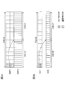
- FIG. 4 is a diagram showing an example of a PDCCH monitoring period in the first embodiment.
- two BWPs (BWP1 and BWP2) are set in the UE.
- the UE performs PDCCH monitoring in cross BWP for BWP 2 in BWP 1.
- the SCS of BWP1 is 15 kHz
- the SCS of BWP2 is 15 * 2 n kHz (n ⁇ 1).
- the symbol length of BWP2 is 1/2 n of the symbol length of BWP1.
- the UE may set K (slot) as a PDCCH monitoring period for BWP1.
- the UE may set K * 2 n (slot) as a PDCCH monitoring period for BWP2.
- K 1.
- the PDCCH monitoring period for BWP1 is one slot in the B-WP1 merology
- the PDCCH monitoring period for BWP2 is two slots in the B-P2 merology (ie, one slot in the BWP1 meromology).
- FIG. 5 is a diagram illustrating another example of the PDCCH monitoring period in the first embodiment.
- two CCs CC1, CC2 are set in the UE.
- the UE performs PDCCH monitoring on the cross carrier for CC2 in CC1.
- the SCS of CC1 is 15 kHz and the SCS of CC2 is 15 * 2 n kHz (n ⁇ 1).
- the symbol length of CC2 is 1/2 n of the symbol length of CC1.
- the UE may set K (slot) as a PDCCH monitoring period for CC1.
- the UE may set K * 2 n (slots) as a PDCCH monitoring period for CC2.
- K 1.
- the PDCCH monitoring period for CC1 is one slot in the ephemeris of CC1
- the PDCCH monitoring period for CC2 is two slots in the merology of CC2 (ie, one slot in the merology of CC1).
- the PDCCH monitoring period for each BWP / CC has shown an example depending on the symbol length of each BWP / CC, it is not limited to this.
- the PDCCH monitoring period for the cross BWP / CC may be determined based on the terminology of the monitor BWP / CC.
- the PDCCH monitoring period for a specific BWP / CC is referred to in order to make PDCCH monitoring periods for cross BWPs / CCs uniform.
- the PDCCH monitoring period may be supported to be a predetermined number of times as. It is preferable that the predetermined multiple is determined based on the neurology for the monitor BWP / CC and the merology for the BWP / CC to be subjected to the cross BWP / CC.
- the predetermined multiple may be, for example, a power of two (2 n (n ⁇ 1)).
- n may be a value based on the ratio between the sterility for the monitor BWP / CC and the merology for the BWP / CC targeted for the cross BWP / CC.
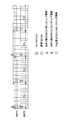
- FIG. 6 is a diagram illustrating an example of a monitoring cycle supported by the UE.
- the UE monitors the PDCCH in BWP1 and obtains at least one SFI of BWP1, 2, 3 and 4.
- the SCS of BWP1, 2, 3 and 4 respectively is 15, 30, 60 and 120 kHz.
- the PDCCH monitoring period for BWP 1 is K slots as shown in FIG. 6, the PDCCH monitoring periods for BWP 2, 3 and 4 may be determined to be 2K, 4K and 8K slots, respectively.
- the PDCCH monitoring period for the cross BWP / CC may be identified based on the terminology for the monitor BWP / CC and the PDCCH monitoring period for the monitor BWP / CC.
- FIG. 7 is a diagram showing an example of the correspondence between the terminology and the monitoring period.
- the leftmost column in FIG. 7 shows the PDCCH monitoring period for the monitor BWP / CC.
- the numerology (SCS) for the monitor BWP / CC is 15 kHz when the period is 1 ms or more, and for the monitor BWP / CC when the period is 0.5 ms.
- the merology (SCS) of is 30 kHz, but is not limited thereto.
- those having a period of more than 20 slots are excluded in each of the numerology, they may be included.
- 40, 80, and 160 may be set at corresponding portions in FIG. 7, respectively.
- the slot length is assumed to be 1 ms in this example, the slot length may be any other value.
- the PDCCH monitoring period for cross BWP / CC is determined to be 2 n (n ⁇ 1) times with reference to the PDCCH monitoring period for monitor BWP / CC.
- n is a value based on the ratio between the neurology for the monitor BWP / CC and the other neurology.
- the base station may notify (configure) the UE of information related to the PDCCH monitoring period for the monitor BWP / CC by higher layer signaling, physical layer signaling, or a combination thereof.
- the base station may notify (configure) the UE of information related to the correspondence between the terminology and the monitoring period by higher layer signaling, physical layer signaling, or a combination thereof.
- the UE can perform PDCCH monitoring for monitor BWP / CC and PDCCH monitoring for cross BWP / CC at the same timing, so the UE load for monitoring can be suitably reduced.
- the PDCCH monitoring period is numerology-agnostic.
- the PDCCH monitoring period may be commonly used regardless of BWP / CC's merology.
- the PDCCH monitoring period for the monitor BWP / CC and the PDCCH monitoring period for the cross BWP / CC may not be aligned to the same timing.
- FIG. 8 is a diagram illustrating an example of a PDCCH monitoring period in the second embodiment. Since the environment assumed by this example is the same as that shown in FIG. 4, the description will not be repeated.
- the UE may be configured such that the common monitoring period (which may be referred to as a cell-specific monitoring period or the like) is K slots.
- the PDCCH monitoring period for BWP1 and the PDCCH monitoring period for BWP2 both have K slots.
- K 1.
- the PDCCH monitoring period for BWP1 is 1 slot in the B-WP1 merology
- the PDCCH monitoring period for BWP2 is 1 slot in the B-P2 merology (ie, 0.5 slot in the BWP1 meromology).
- monitoring of the PDCCH for BWP 2 may be performed at a time when there is no PDCCH (indicated by “x” in FIG. 8) period).
- FIG. 9 is a diagram illustrating another example of the PDCCH monitoring period in the second embodiment. Since the environment assumed by this example is the same as that shown in FIG. 5, the description will not be repeated.
- the UE may be configured such that the common monitoring period (which may be referred to as a cell-specific monitoring period or the like) is K slots.
- the PDCCH monitoring cycle for CC1 and the PDCCH monitoring cycle for CC2 both have K slots.
- K 1.
- the PDCCH monitoring period for CC1 is one slot in the ephemeris of CC1
- the PDCCH monitoring period for CC2 is one slot in the merology of CC2 (that is, 0.5 slots in the merology of CC1).
- monitoring of PDCCHs for CC2 may be performed at times when PDCCHs do not exist (indicated by “x” in FIG. 9) period).
- the base station may notify the UE of the information on the cell specific monitoring period by higher layer signaling, physical layer signaling or a combination thereof.
- the UE can easily determine that the PDCCH monitoring period for the monitor BWP / CC and the PDCCH monitoring period for the cross BWP / CC are the same, so that the UE load for grasping the monitoring period can be suitably reduced.
- the base station for each BWP / CC, information on PDCCH monitoring cycle for each BWP / CC (information on BWP specific monitoring cycle, information on CC specific monitoring cycle), upper layer signaling, physical layer signaling, or a combination thereof May notify the UE.
- the PDCCH monitoring period may be configured to be BWP / CC specific.
- the PDCCH monitoring period for each BWP / CC may be set to be different even if the B and C types have the same (for example, the same SCS value).
- the PDCCH monitoring period may be set independently, regardless of the BGM / CC-based terminology.
- wireless communication system Wireless communication system
- communication is performed using any one or a combination of the wireless communication methods according to the above embodiments of the present disclosure.
- FIG. 10 is a diagram showing an example of a schematic configuration of a wireless communication system according to an embodiment.
- the radio communication system 1 applies carrier aggregation (CA) and / or dual connectivity (DC) in which a plurality of basic frequency blocks (component carriers) each having a system bandwidth (for example, 20 MHz) of the LTE system as one unit are integrated. can do.
- CA carrier aggregation
- DC dual connectivity
- the wireless communication system 1 includes LTE (Long Term Evolution), LTE-A (LTE-Advanced), LTE-B (LTE-Beyond), SUPER 3G, IMT-Advanced, 4G (4th generation mobile communication system), and 5G. It may be called (5th generation mobile communication system), NR (New Radio), FRA (Future Radio Access), New-RAT (Radio Access Technology) or the like, or may be called a system for realizing these.
- the radio communication system 1 includes a radio base station 11 forming a macrocell C1 with a relatively wide coverage, and radio base stations 12 (12a to 12c) disposed in the macrocell C1 and forming a small cell C2 narrower than the macrocell C1. And. Moreover, the user terminal 20 is arrange
- the user terminal 20 can be connected to both the radio base station 11 and the radio base station 12. It is assumed that the user terminal 20 simultaneously uses the macro cell C1 and the small cell C2 using CA or DC. Also, the user terminal 20 may apply CA or DC using a plurality of cells (CCs) (for example, 5 or less CCs, 6 or more CCs).
- CCs cells
- Communication can be performed between the user terminal 20 and the radio base station 11 using a relatively low frequency band (for example, 2 GHz) and a narrow bandwidth carrier (also called an existing carrier, legacy carrier, etc.).
- a carrier having a wide bandwidth in a relatively high frequency band for example, 3.5 GHz, 5 GHz, etc.
- the configuration of the frequency band used by each wireless base station is not limited to this.
- the user terminal 20 can perform communication in each cell using time division duplex (TDD) and / or frequency division duplex (FDD). Also, in each cell (carrier), a single numerology may be applied, or a plurality of different numerologies may be applied.
- TDD time division duplex
- FDD frequency division duplex
- Numerology may be communication parameters applied to transmission and / or reception of a certain signal and / or channel, for example, subcarrier spacing, bandwidth, symbol length, cyclic prefix length, subframe length It may indicate at least one of TTI length, number of symbols per TTI, radio frame configuration, specific filtering processing performed by the transceiver in the frequency domain, and specific windowing processing performed by the transceiver in the time domain. For example, in the case where subcarrier intervals of constituent OFDM symbols are different and / or the number of OFDM symbols is different for a certain physical channel, the neurology may be referred to as different.
- the wireless base station 11 and the wireless base station 12 are connected by wire (for example, an optical fiber conforming to CPRI (Common Public Radio Interface), X2 interface, etc.) or wirelessly It may be done.
- wire for example, an optical fiber conforming to CPRI (Common Public Radio Interface), X2 interface, etc.
- CPRI Common Public Radio Interface
- X2 interface etc.
- the radio base station 11 and each radio base station 12 are connected to the higher station apparatus 30 and connected to the core network 40 via the higher station apparatus 30.
- the upper station apparatus 30 includes, for example, an access gateway apparatus, a radio network controller (RNC), a mobility management entity (MME), and the like, but is not limited thereto. Further, each wireless base station 12 may be connected to the higher station apparatus 30 via the wireless base station 11.
- RNC radio network controller
- MME mobility management entity
- the radio base station 11 is a radio base station having a relatively wide coverage, and may be called a macro base station, an aggregation node, an eNB (eNodeB), a transmission / reception point, or the like.
- the radio base station 12 is a radio base station having local coverage, and is a small base station, a micro base station, a pico base station, a femto base station, a HeNB (Home eNodeB), an RRH (Remote Radio Head), transmission and reception It may be called a point or the like.
- the radio base stations 11 and 12 are not distinguished, they are collectively referred to as the radio base station 10.
- Each user terminal 20 is a terminal compatible with various communication schemes such as LTE and LTE-A, and may include not only mobile communication terminals (mobile stations) but also fixed communication terminals (fixed stations).
- orthogonal frequency division multiple access (OFDMA) is applied to the downlink as a radio access scheme, and single carrier frequency division multiple access (SC-FDMA: single carrier) to the uplink.
- SC-FDMA single carrier frequency division multiple access
- Frequency Division Multiple Access and / or OFDMA is applied.
- OFDMA is a multicarrier transmission scheme in which a frequency band is divided into a plurality of narrow frequency bands (subcarriers) and data is mapped to each subcarrier to perform communication.
- SC-FDMA is a single carrier transmission that reduces interference between terminals by dividing the system bandwidth into a band configured by one or continuous resource blocks for each terminal, and a plurality of terminals use different bands. It is a system.
- the uplink and downlink radio access schemes are not limited to these combinations, and other radio access schemes may be used.
- a downlink shared channel (PDSCH: Physical Downlink Shared Channel) shared by each user terminal 20, a broadcast channel (PBCH: Physical Broadcast Channel), a downlink L1 / L2 control channel, etc. are used as downlink channels. Used. User data, upper layer control information, SIB (System Information Block), etc. are transmitted by the PDSCH. Also, a MIB (Master Information Block) is transmitted by the PBCH.
- PDSCH Physical Downlink Shared Channel
- PBCH Physical Broadcast Channel
- SIB System Information Block
- MIB Master Information Block
- the downlink L1 / L2 control channel includes PDCCH (Physical Downlink Control Channel), EPDCCH (Enhanced Physical Downlink Control Channel), PCFICH (Physical Control Format Indicator Channel), PHICH (Physical Hybrid-ARQ Indicator Channel) and the like.
- Downlink control information (DCI) including scheduling information of PDSCH and / or PUSCH is transmitted by PDCCH.
- scheduling information may be notified by DCI.
- DCI scheduling DL data reception may be referred to as DL assignment
- DCI scheduling UL data transmission may be referred to as UL grant.
- the number of OFDM symbols used for PDCCH is transmitted by PCFICH.
- Delivery confirmation information (for example, also referred to as retransmission control information, HARQ-ACK, and ACK / NACK) of HARQ (Hybrid Automatic Repeat reQuest) for the PUSCH is transmitted by the PHICH.
- the EPDCCH is frequency division multiplexed with a PDSCH (downlink shared data channel), and is used for transmission such as DCI, similarly to the PDCCH.
- an uplink shared channel (PUSCH: Physical Uplink Shared Channel) shared by each user terminal 20, an uplink control channel (PUCCH: Physical Uplink Control Channel), a random access channel (PRACH: Physical Random Access Channel) or the like is used.
- User data, upper layer control information, etc. are transmitted by PUSCH.
- downlink radio quality information (CQI: Channel Quality Indicator), delivery confirmation information, scheduling request (SR: Scheduling Request) and the like are transmitted by the PUCCH.
- the PRACH transmits a random access preamble for establishing a connection with a cell.
- a cell-specific reference signal (CRS: Cell-specific Reference Signal), a channel state information reference signal (CSI-RS: Channel State Information-Reference Signal), a demodulation reference signal (DMRS: DeModulation Reference Signal, positioning reference signal (PRS), etc.
- CRS Cell-specific Reference Signal
- CSI-RS Channel State Information-Reference Signal
- DMRS DeModulation Reference Signal
- PRS positioning reference signal
- SRS Sounding Reference Signal
- DMRS demodulation reference signal
- PRS positioning reference signal
- DMRS Demodulation reference signal
- PRS positioning reference signal
- FIG. 11 is a diagram illustrating an example of the entire configuration of the radio base station according to an embodiment.
- the radio base station 10 includes a plurality of transmitting and receiving antennas 101, an amplifier unit 102, a transmitting and receiving unit 103, a baseband signal processing unit 104, a call processing unit 105, and a transmission path interface 106. Note that each of the transmitting and receiving antenna 101, the amplifier unit 102, and the transmitting and receiving unit 103 may be configured to include one or more.
- User data transmitted from the radio base station 10 to the user terminal 20 by downlink is input from the higher station apparatus 30 to the baseband signal processing unit 104 via the transmission path interface 106.
- the baseband signal processing unit 104 performs packet data convergence protocol (PDCP) layer processing, user data division / combination, RLC layer transmission processing such as RLC (Radio Link Control) retransmission control, and MAC (Medium Access) for user data.
- Control Transmission processing such as retransmission control (for example, HARQ transmission processing), scheduling, transmission format selection, channel coding, inverse fast Fourier transform (IFFT) processing, precoding processing, etc. It is transferred to 103. Further, transmission processing such as channel coding and inverse fast Fourier transform is also performed on the downlink control signal and transferred to the transmission / reception unit 103.
- the transmission / reception unit 103 converts the baseband signal output from the baseband signal processing unit 104 for each antenna into a radio frequency band and transmits the baseband signal.
- the radio frequency signal frequency-converted by the transmitting and receiving unit 103 is amplified by the amplifier unit 102 and transmitted from the transmitting and receiving antenna 101.
- the transmission / reception unit 103 can be configured of a transmitter / receiver, a transmission / reception circuit, or a transmission / reception device described based on the common recognition in the technical field according to the present disclosure.
- the transmitting and receiving unit 103 may be configured as an integrated transmitting and receiving unit, or may be configured from a transmitting unit and a receiving unit.
- the radio frequency signal received by the transmission / reception antenna 101 is amplified by the amplifier unit 102.
- the transmitting and receiving unit 103 receives the upstream signal amplified by the amplifier unit 102.
- the transmission / reception unit 103 frequency-converts the received signal into a baseband signal and outputs the result to the baseband signal processing unit 104.
- the baseband signal processing unit 104 performs Fast Fourier Transform (FFT) processing, Inverse Discrete Fourier Transform (IDFT) processing, and error correction on user data included in the input upstream signal. Decoding, reception processing of MAC retransmission control, and reception processing of RLC layer and PDCP layer are performed, and are transferred to the higher station apparatus 30 via the transmission path interface 106.
- the call processing unit 105 performs call processing (setting, release, etc.) of the communication channel, state management of the radio base station 10, management of radio resources, and the like.
- the transmission path interface 106 transmits and receives signals to and from the higher station apparatus 30 via a predetermined interface. Also, the transmission path interface 106 transmits / receives signals (backhaul signaling) to / from the other wireless base station 10 via an inter-base station interface (for example, an optical fiber conforming to CPRI (Common Public Radio Interface), X2 interface). May be
- an inter-base station interface for example, an optical fiber conforming to CPRI (Common Public Radio Interface), X2 interface.
- the transmission / reception unit 103 transmits downlink control information (DCI) to the user terminal 20 via the normal PDCCH, GC-PDCCH, and the like.
- DCI downlink control information
- the transmitting / receiving unit 103 includes information on the PDCCH monitoring cycle for the monitor BWP / CC, information on the correspondence relationship between the numerology and the monitoring cycle, information on the cell-specific monitoring cycle, information on the BWP-specific monitoring cycle, and information on the CC-specific monitoring cycle. , Etc. may be transmitted to the user terminal 20.
- FIG. 12 is a diagram illustrating an example of a functional configuration of a wireless base station according to an embodiment of the present disclosure.
- the functional block of the characteristic part in this embodiment is mainly shown, and it may be assumed that the wireless base station 10 also has another functional block required for wireless communication.
- the baseband signal processing unit 104 at least includes a control unit (scheduler) 301, a transmission signal generation unit 302, a mapping unit 303, a reception signal processing unit 304, and a measurement unit 305. Note that these configurations may be included in the wireless base station 10, and some or all of the configurations may not be included in the baseband signal processing unit 104.
- a control unit (scheduler) 301 performs control of the entire radio base station 10.
- the control unit 301 can be configured of a controller, a control circuit, or a control device described based on the common recognition in the technical field according to the present disclosure.
- the control unit 301 controls, for example, generation of a signal in the transmission signal generation unit 302, assignment of a signal in the mapping unit 303, and the like. Further, the control unit 301 controls reception processing of a signal in the reception signal processing unit 304, measurement of a signal in the measurement unit 305, and the like.
- the control unit 301 schedules (for example, resources) system information, downlink data signals (for example, signals transmitted on PDSCH), downlink control signals (for example, signals transmitted on PDCCH and / or EPDCCH, delivery confirmation information, etc.) Control allocation). Further, the control unit 301 controls generation of the downlink control signal, the downlink data signal, and the like based on the result of determining whether the retransmission control for the uplink data signal is necessary or not.
- the control unit 301 controls scheduling of synchronization signals (for example, PSS (Primary Synchronization Signal) / SSS (Secondary Synchronization Signal), downlink reference signals (for example, CRS, CSI-RS, DMRS) and the like.
- synchronization signals for example, PSS (Primary Synchronization Signal) / SSS (Secondary Synchronization Signal)
- SSS Secondary Synchronization Signal
- CRS Channel Reference Signal
- CSI-RS CSI-RS
- DMRS Downlink reference signals
- the control unit 301 may use an uplink data signal (for example, a signal transmitted on PUSCH), an uplink control signal (for example, a signal transmitted on PUCCH and / or PUSCH, delivery confirmation information, etc.), a random access preamble (for example, PRACH). Control the scheduling of transmitted signals, uplink reference signals, etc.
- an uplink data signal for example, a signal transmitted on PUSCH
- an uplink control signal for example, a signal transmitted on PUCCH and / or PUSCH, delivery confirmation information, etc.
- a random access preamble for example, PRACH
- the control unit 301 is different from another frequency resource (for example, the above-mentioned particular CC) based on the monitoring cycle of the downlink control channel for control in a predetermined frequency resource (for example, a particular CC, a particular BWP) Control may be performed to transmit information for determining the monitoring cycle of the downlink control channel for control in CC, BWP different from the above-described specific BWP, and the like.
- a predetermined frequency resource for example, a particular CC, a particular BWP
- the downlink control channel here may be, for example, normal PDCCH, GC-PDCCH, or the like. Further, control in the frequency resource may be transmission / reception processing of the frequency resource based on SFI, transmission / reception processing of the frequency resource based on scheduling (DL assignment, UL grant, etc.), or the like.
- the transmission signal generation unit 302 generates a downlink signal (a downlink control signal, a downlink data signal, a downlink reference signal, and the like) based on an instruction from the control unit 301, and outputs the downlink signal to the mapping unit 303.
- the transmission signal generation unit 302 can be configured from a signal generator, a signal generation circuit, or a signal generation device described based on the common recognition in the technical field according to the present disclosure.
- the transmission signal generation unit 302 generates, for example, DL assignment for notifying downlink data allocation information and / or UL grant for notifying uplink data allocation information, based on an instruction from the control unit 301.
- DL assignment and UL grant are both DCI and follow DCI format.
- coding processing and modulation processing are performed on the downlink data signal according to a coding rate, a modulation method, and the like determined based on channel state information (CSI: Channel State Information) and the like from each user terminal 20.
- CSI Channel State Information
- Mapping section 303 maps the downlink signal generated by transmission signal generation section 302 to a predetermined radio resource based on an instruction from control section 301, and outputs the mapped downlink signal to transmission / reception section 103.
- the mapping unit 303 can be configured from a mapper, a mapping circuit or a mapping device described based on the common recognition in the technical field according to the present disclosure.
- the reception signal processing unit 304 performs reception processing (for example, demapping, demodulation, decoding, and the like) on the reception signal input from the transmission / reception unit 103.
- the reception signal is, for example, an uplink signal (uplink control signal, uplink data signal, uplink reference signal, etc.) transmitted from the user terminal 20.
- the received signal processing unit 304 can be configured from a signal processor, a signal processing circuit or a signal processing device described based on the common recognition in the technical field according to the present disclosure.
- the reception signal processing unit 304 outputs the information decoded by the reception process to the control unit 301. For example, when the PUCCH including the HARQ-ACK is received, the HARQ-ACK is output to the control unit 301. Further, the reception signal processing unit 304 outputs the reception signal and / or the signal after reception processing to the measurement unit 305.
- the measurement unit 305 performs measurement on the received signal.
- the measuring unit 305 can be configured from a measuring device, a measuring circuit, or a measuring device described based on the common recognition in the technical field according to the present disclosure.
- the measurement unit 305 may perform Radio Resource Management (RRM) measurement, Channel State Information (CSI) measurement, and the like based on the received signal.
- the measurement unit 305 may use received power (for example, reference signal received power (RSRP)), received quality (for example, reference signal received quality (RSRQ), signal to interference plus noise ratio (SINR), signal to noise ratio (SNR)). , Signal strength (e.g., received signal strength indicator (RSSI)), channel information (e.g., CSI), and the like.
- RSRP reference signal received power
- RSSI received signal strength indicator
- CSI channel information
- the measurement result may be output to the control unit 301.
- FIG. 13 is a diagram showing an example of the entire configuration of a user terminal according to an embodiment.
- the user terminal 20 includes a plurality of transmitting and receiving antennas 201, an amplifier unit 202, a transmitting and receiving unit 203, a baseband signal processing unit 204, and an application unit 205.
- each of the transmitting and receiving antenna 201, the amplifier unit 202, and the transmitting and receiving unit 203 may be configured to include one or more.
- the radio frequency signal received by the transmission / reception antenna 201 is amplified by the amplifier unit 202.
- the transmitting and receiving unit 203 receives the downlink signal amplified by the amplifier unit 202.
- the transmission / reception unit 203 frequency-converts the received signal into a baseband signal and outputs the result to the baseband signal processing unit 204.
- the transmission / reception unit 203 can be configured of a transmitter / receiver, a transmission / reception circuit, or a transmission / reception device described based on the common recognition in the technical field according to the present disclosure.
- the transmission / reception unit 203 may be configured as an integrated transmission / reception unit, or may be configured from a transmission unit and a reception unit.
- the baseband signal processing unit 204 performs reception processing of FFT processing, error correction decoding, retransmission control, and the like on the input baseband signal.
- the downlink user data is transferred to the application unit 205.
- the application unit 205 performs processing on a layer higher than the physical layer and the MAC layer. Moreover, broadcast information may also be transferred to the application unit 205 among downlink data.
- uplink user data is input from the application unit 205 to the baseband signal processing unit 204.
- the baseband signal processing unit 204 performs transmission processing of retransmission control (for example, transmission processing of HARQ), channel coding, precoding, discrete Fourier transform (DFT) processing, IFFT processing, etc. It is transferred to 203.
- the transmission / reception unit 203 converts the baseband signal output from the baseband signal processing unit 204 into a radio frequency band and transmits it.
- the radio frequency signal frequency-converted by the transmitting and receiving unit 203 is amplified by the amplifier unit 202 and transmitted from the transmitting and receiving antenna 201.
- the transmission / reception unit 203 may monitor the downlink control channel for control in another frequency resource on a predetermined frequency resource.
- the monitoring cycle, period, and the like of the downlink control channel may be determined by the control unit 401 described later.
- the transmitting and receiving unit 203 receives downlink control information (DCI) via the normal PDCCH, GC-PDCCH, and the like.
- DCI may include SFI.
- the transmitting / receiving unit 203 includes information on the PDCCH monitoring cycle for the monitor BWP / CC, information on the correspondence relationship between the terminology and the monitoring cycle, information on the cell-specific monitoring cycle, information on the BWP-specific monitoring cycle, and information on the CC-specific monitoring cycle. , Etc. may be received from the wireless base station 10.
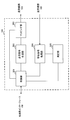
- FIG. 14 is a diagram illustrating an example of a functional configuration of a user terminal according to an embodiment.
- the functional block of the characteristic part in this embodiment is mainly shown, and it may be assumed that the user terminal 20 also has another functional block required for wireless communication.
- the baseband signal processing unit 204 included in the user terminal 20 at least includes a control unit 401, a transmission signal generation unit 402, a mapping unit 403, a reception signal processing unit 404, and a measurement unit 405. Note that these configurations may be included in the user terminal 20, and some or all of the configurations may not be included in the baseband signal processing unit 204.
- the control unit 401 controls the entire user terminal 20.
- the control unit 401 can be configured of a controller, a control circuit, or a control device described based on the common recognition in the technical field according to the present disclosure.
- the control unit 401 controls, for example, generation of a signal in the transmission signal generation unit 402, assignment of a signal in the mapping unit 403, and the like. Further, the control unit 401 controls reception processing of signals in the reception signal processing unit 404, measurement of signals in the measurement unit 405, and the like.
- the control unit 401 acquires the downlink control signal and the downlink data signal transmitted from the radio base station 10 from the reception signal processing unit 404.
- the control unit 401 controls the generation of the uplink control signal and / or the uplink data signal based on the result of determining the necessity of the retransmission control for the downlink control signal and / or the downlink data signal.
- the control unit 401 is different from another frequency resource (for example, the above-mentioned specific CC) based on the monitoring cycle of the downlink control channel for control in a predetermined frequency resource (for example, a specific CC, a specific BWP)
- a predetermined frequency resource for example, a specific CC, a specific BWP
- the monitoring cycle of the downlink control channel for control in CC, BWP different from the above-mentioned specific BWP, etc. may be determined.
- the “downlink control channel” here may be, for example, normal PDCCH, GC-PDCCH, or the like.
- control on frequency resource may be transmission / reception processing of the frequency resource based on SFI, transmission / reception processing of the frequency resource based on scheduling (DL assignment, UL grant, etc.), or the like.
- the control unit 401 may perform control on frequency resources.
- the control unit 401 is a downlink control channel for control in the other frequency resource based on the monitoring cycle of the downlink control channel for control in the predetermined frequency resource and the numerology used in the other frequency resource.
- the monitoring cycle of may be determined (see the first embodiment).
- the control unit 401 may determine that the monitoring cycle of the downlink control channel for control in the other frequency resource is the same as the monitoring cycle of the downlink control channel for control in the predetermined frequency resource (No. See embodiment 2). For example, having the same monitoring period corresponding to different neurology may mean that the number of slots indicating the monitoring period is the same.
- control unit 401 may determine the monitoring cycle of the downlink control channel for control in the other frequency resource based on the numerology for the other frequency resource.
- the control unit 401 may determine the monitoring cycle of the downlink control channel for control on the predetermined frequency resource based on the neurology for the predetermined frequency resource.
- the control unit 401 may determine the monitoring cycle of the downlink control channel for control in another frequency resource based on the numerology for a specific frequency resource.
- control unit 401 When the control unit 401 acquires various types of information notified from the radio base station 10 from the received signal processing unit 404, the control unit 401 may update parameters used for control based on the information.
- the transmission signal generation unit 402 generates an uplink signal (uplink control signal, uplink data signal, uplink reference signal or the like) based on an instruction from the control unit 401, and outputs the uplink signal to the mapping unit 403.
- the transmission signal generation unit 402 can be configured from a signal generator, a signal generation circuit or a signal generation device described based on the common recognition in the technical field according to the present disclosure.
- the transmission signal generation unit 402 generates, for example, an uplink control signal related to delivery confirmation information, channel state information (CSI), and the like based on an instruction from the control unit 401. Further, the transmission signal generation unit 402 generates an uplink data signal based on an instruction from the control unit 401. For example, when the downlink control signal notified from the radio base station 10 includes a UL grant, the transmission signal generation unit 402 is instructed by the control unit 401 to generate an uplink data signal.
- CSI channel state information
- Mapping section 403 maps the uplink signal generated by transmission signal generation section 402 to a radio resource based on an instruction from control section 401, and outputs the uplink signal to transmission / reception section 203.
- the mapping unit 403 can be configured from a mapper, a mapping circuit, or a mapping device described based on the common recognition in the technical field according to the present disclosure.
- the reception signal processing unit 404 performs reception processing (for example, demapping, demodulation, decoding, and the like) on the reception signal input from the transmission / reception unit 203.
- the reception signal is, for example, a downlink signal (a downlink control signal, a downlink data signal, a downlink reference signal, or the like) transmitted from the radio base station 10.
- the received signal processing unit 404 can be configured from a signal processor, a signal processing circuit or a signal processing device described based on the common recognition in the technical field according to the present disclosure. Further, the received signal processing unit 404 can configure a receiving unit according to the present disclosure.
- the reception signal processing unit 404 outputs the information decoded by the reception process to the control unit 401.
- the received signal processing unit 404 outputs, for example, broadcast information, system information, RRC signaling, DCI, and the like to the control unit 401. Further, the reception signal processing unit 404 outputs the reception signal and / or the signal after reception processing to the measurement unit 405.
- the measurement unit 405 performs measurement on the received signal.
- the measuring unit 405 can be configured from a measuring device, a measuring circuit, or a measuring device described based on the common recognition in the technical field according to the present disclosure.
- the measurement unit 405 may perform RRM measurement, CSI measurement, and the like based on the received signal.
- the measurement unit 405 may measure reception power (for example, RSRP), reception quality (for example, RSRQ, SINR, SNR), signal strength (for example, RSSI), channel information (for example, CSI), and the like.
- the measurement result may be output to the control unit 401.
- each functional block (components) are realized by any combination of hardware and / or software.
- the implementation method of each functional block is not particularly limited. That is, each functional block may be realized using one physically and / or logically coupled device, or directly and / or two or more physically and / or logically separated devices. Or it may connect indirectly (for example, using a wire communication and / or radio), and it may be realized using a plurality of these devices.
- a wireless base station, a user terminal, and the like in an embodiment of the present disclosure may function as a computer that performs the processing of the wireless communication method of the present disclosure.
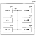
- FIG. 15 is a diagram illustrating an example of a hardware configuration of a wireless base station and a user terminal according to an embodiment.
- the above-described wireless base station 10 and user terminal 20 may be physically configured as a computer device including a processor 1001, a memory 1002, a storage 1003, a communication device 1004, an input device 1005, an output device 1006, a bus 1007 and the like. Good.
- the term “device” can be read as a circuit, a device, a unit, or the like.
- the hardware configuration of the radio base station 10 and the user terminal 20 may be configured to include one or more of the devices illustrated in the figure, or may be configured without including some devices.
- processor 1001 may be implemented by one or more chips.
- Each function in the radio base station 10 and the user terminal 20 is calculated by causing the processor 1001 to read predetermined software (program) on hardware such as the processor 1001 and the memory 1002, and the communication device 1004 is performed. This is realized by controlling communication, and controlling reading and / or writing of data in the memory 1002 and the storage 1003.
- the processor 1001 operates, for example, an operating system to control the entire computer.
- the processor 1001 may be configured by a central processing unit (CPU) including an interface with a peripheral device, a control device, an arithmetic device, a register, and the like.
- CPU central processing unit
- the above-described baseband signal processing unit 104 (204), call processing unit 105, and the like may be realized by the processor 1001.
- the processor 1001 reads a program (program code), a software module, data, and the like from the storage 1003 and / or the communication device 1004 to the memory 1002, and executes various processing according to these.
- a program a program that causes a computer to execute at least a part of the operations described in the above-described embodiment is used.
- the control unit 401 of the user terminal 20 may be realized by a control program stored in the memory 1002 and operating in the processor 1001, or may be realized similarly for other functional blocks.
- the memory 1002 is a computer readable recording medium, and for example, at least at least a read only memory (ROM), an erasable programmable ROM (EPROM), an electrically EPROM (EEPROM), a random access memory (RAM), or any other suitable storage medium. It may be configured by one.
- the memory 1002 may be called a register, a cache, a main memory (main storage device) or the like.
- the memory 1002 may store a program (program code), a software module, and the like that can be executed to implement the wireless communication method according to an embodiment.
- the storage 1003 is a computer readable recording medium, and for example, a flexible disk, a floppy (registered trademark) disk, a magneto-optical disk (for example, a compact disk (CD-ROM (Compact Disc ROM), etc.), a digital versatile disk, Blu-ray® disc), removable disc, hard disc drive, smart card, flash memory device (eg card, stick, key drive), magnetic stripe, database, server, at least one other suitable storage medium May be configured by The storage 1003 may be called an auxiliary storage device.
- a computer readable recording medium for example, a flexible disk, a floppy (registered trademark) disk, a magneto-optical disk (for example, a compact disk (CD-ROM (Compact Disc ROM), etc.), a digital versatile disk, Blu-ray® disc), removable disc, hard disc drive, smart card, flash memory device (eg card, stick, key drive), magnetic stripe, database, server, at least one other suitable storage medium May be configured by
- the communication device 1004 is hardware (transmission / reception device) for performing communication between computers via a wired and / or wireless network, and is also called, for example, a network device, a network controller, a network card, a communication module, or the like.
- the communication device 1004 includes, for example, a high frequency switch, a duplexer, a filter, a frequency synthesizer, and the like to realize, for example, frequency division duplex (FDD) and / or time division duplex (TDD). It may be configured.
- FDD frequency division duplex
- TDD time division duplex
- the transmission / reception antenna 101 (201), the amplifier unit 102 (202), the transmission / reception unit 103 (203), the transmission path interface 106, and the like described above may be realized by the communication device 1004.
- the input device 1005 is an input device (for example, a keyboard, a mouse, a microphone, a switch, a button, a sensor, and the like) that receives an input from the outside.
- the output device 1006 is an output device (for example, a display, a speaker, a light emitting diode (LED) lamp, and the like) that performs output to the outside.
- the input device 1005 and the output device 1006 may be integrated (for example, a touch panel).
- each device such as the processor 1001 and the memory 1002 is connected by a bus 1007 for communicating information.
- the bus 1007 may be configured using a single bus, or may be configured using different buses between devices.
- radio base station 10 and the user terminal 20 may be microprocessors, digital signal processors (DSPs), application specific integrated circuits (ASICs), programmable logic devices (PLDs), field programmable gate arrays (FPGAs), etc.
- DSPs digital signal processors
- ASICs application specific integrated circuits
- PLDs programmable logic devices
- FPGAs field programmable gate arrays
- Hardware may be included, and part or all of each functional block may be realized using the hardware.
- processor 1001 may be implemented using at least one of these hardware.
- the channels and / or symbols may be signaling.
- the signal may be a message.
- the reference signal may be abbreviated as RS (Reference Signal), and may be referred to as a pilot (Pilot), a pilot signal or the like according to an applied standard.
- a component carrier CC: Component Carrier
- CC Component Carrier
- the radio frame may be configured by one or more periods (frames) in the time domain.
- Each of the one or more periods (frames) that constitute a radio frame may be referred to as a subframe.
- a subframe may be configured by one or more slots in the time domain.
- the subframes may be of a fixed time length (e.g., 1 ms) independent of the neurology.
- the slot may be configured by one or more symbols in the time domain (such as orthogonal frequency division multiplexing (OFDM) symbols, single carrier frequency division multiple access (SC-FDMA) symbols, etc.).
- the slot may be a time unit based on the neurology.
- the slot may include a plurality of minislots. Each minislot may be configured by one or more symbols in the time domain. Minislots may also be referred to as subslots.
- a radio frame, a subframe, a slot, a minislot and a symbol all represent time units when transmitting a signal.
- subframes, slots, minislots and symbols other names corresponding to each may be used.
- one subframe may be referred to as a transmission time interval (TTI)
- TTI transmission time interval
- a plurality of consecutive subframes may be referred to as a TTI
- one slot or one minislot may be referred to as a TTI.
- TTI transmission time interval
- the subframe and / or TTI may be a subframe (1 ms) in existing LTE, a period shorter than 1 ms (eg, 1-13 symbols), or a period longer than 1 ms. It may be.
- the unit representing TTI may be called a slot, a minislot, etc. instead of a subframe.
- TTI refers to, for example, the minimum time unit of scheduling in wireless communication.
- the radio base station performs scheduling to assign radio resources (frequency bandwidth usable in each user terminal, transmission power, etc.) to each user terminal in TTI units.
- radio resources frequency bandwidth usable in each user terminal, transmission power, etc.
- the TTI may be a transmission time unit of a channel encoded data packet (transport block), a code block, and / or a codeword, or may be a processing unit such as scheduling and link adaptation. Note that, when a TTI is given, the time interval (eg, the number of symbols) in which the transport block, the code block, and / or the codeword is actually mapped may be shorter than the TTI.
- one or more TTIs may be the minimum time unit of scheduling.
- the number of slots (the number of minislots) constituting the minimum time unit of the scheduling may be controlled.
- a TTI having a time length of 1 ms may be referred to as a normal TTI (TTI in LTE Rel. 8-12), a normal TTI, a long TTI, a normal subframe, a normal subframe, a long subframe, or the like.
- a TTI shorter than a normal TTI may be referred to as a shortened TTI, a short TTI, a partial TTI (partial or fractional TTI), a shortened subframe, a short subframe, a minislot, a subslot, or the like.
- a long TTI for example, a normal TTI, a subframe, etc.
- a short TTI eg, a shortened TTI, etc.
- a resource block is a resource allocation unit in time domain and frequency domain, and may include one or more consecutive subcarriers (subcarriers) in the frequency domain. Also, an RB may include one or more symbols in the time domain, and may be one slot, one minislot, one subframe, or one TTI in length. One TTI and one subframe may be respectively configured by one or more resource blocks. Note that one or more RBs may be a physical resource block (PRB: Physical RB), a subcarrier group (SCG: Sub-Carrier Group), a resource element group (REG: Resource Element Group), a PRB pair, an RB pair, etc. It may be called.
- PRB Physical resource block
- SCG Sub-Carrier Group
- REG Resource Element Group
- a resource block may be configured by one or more resource elements (RE: Resource Element).
- RE Resource Element
- one RE may be one subcarrier and one symbol radio resource region.
- the above-described structures such as the radio frame, subframe, slot, minislot and symbol are merely examples.
- the number of subframes included in a radio frame the number of slots per subframe or radio frame, the number of minislots included in a slot, the number of symbols and RBs included in a slot or minislot, included in an RB
- the number of subcarriers, as well as the number of symbols in a TTI, the symbol length, the cyclic prefix (CP) length, and other configurations can be variously changed.
- the information, parameters, etc. described in the present specification may be expressed using absolute values, may be expressed using relative values from predetermined values, or other corresponding information. May be represented.
- radio resources may be indicated by a predetermined index.
- the names used for parameters and the like in the present specification are not limited names in any respect.
- various channels PUCCH (Physical Uplink Control Channel), PDCCH (Physical Downlink Control Channel), etc.
- information elements can be identified by any suitable names, various assignments are made to these various channels and information elements.
- the name is not limited in any way.
- data, instructions, commands, information, signals, bits, symbols, chips etc may be voltage, current, electromagnetic waves, magnetic fields or particles, optical fields or photons, or any of these May be represented by a combination of
- information, signals, etc. may be output from the upper layer to the lower layer and / or from the lower layer to the upper layer.
- Information, signals, etc. may be input / output via a plurality of network nodes.
- the input / output information, signals and the like may be stored in a specific place (for example, a memory) or may be managed using a management table. Information, signals, etc. input and output can be overwritten, updated or added. The output information, signals and the like may be deleted. The input information, signals and the like may be transmitted to other devices.
- notification of information is not limited to the aspects / embodiments described herein, and may be performed using other methods.
- notification of information may be physical layer signaling (eg, downlink control information (DCI), uplink control information (UCI)), upper layer signaling (eg, RRC (Radio Resource Control) signaling, It may be implemented by broadcast information (Master Information Block (MIB), System Information Block (SIB), etc.), MAC (Medium Access Control) signaling, other signals, or a combination thereof.
- DCI downlink control information
- UCI uplink control information
- RRC Radio Resource Control
- MIB Master Information Block
- SIB System Information Block
- MAC Medium Access Control
- the physical layer signaling may be called L1 / L2 (Layer 1 / Layer 2) control information (L1 / L2 control signal), L1 control information (L1 control signal), or the like.
- RRC signaling may be referred to as an RRC message, and may be, for example, an RRC connection setup (RRC Connection Setup) message, an RRC connection reconfiguration (RRC Connection Reconfiguration) message, or the like.
- MAC signaling may be notified using, for example, a MAC control element (MAC CE (Control Element)).
- notification of predetermined information is not limited to explicit notification, but implicitly (for example, by not notifying the predetermined information or other information Notification may be performed).
- the determination may be performed by a value (0 or 1) represented by one bit, or may be performed by a boolean value represented by true or false. , Numerical comparison (for example, comparison with a predetermined value) may be performed.
- Software may be called software, firmware, middleware, microcode, hardware description language, or any other name, and may be instructions, instruction sets, codes, code segments, program codes, programs, subprograms, software modules. Should be interpreted broadly to mean applications, software applications, software packages, routines, subroutines, objects, executables, threads of execution, procedures, functions, etc.
- software, instructions, information, etc. may be sent and received via a transmission medium.
- software may use a wired technology (coaxial cable, fiber optic cable, twisted pair, digital subscriber line (DSL), etc.) and / or a wireless technology (infrared, microwave, etc.), a website, a server
- wired technology coaxial cable, fiber optic cable, twisted pair, digital subscriber line (DSL), etc.
- wireless technology infrared, microwave, etc.
- system and "network” as used herein are used interchangeably.
- base station Base Station
- radio base station eNB
- gNB gigad Generation
- cell cell
- cell group cell group
- carrier carrier
- carrier may be used interchangeably.
- a base station may also be called in terms of a fixed station (Node station), NodeB, eNodeB (eNB), access point (access point), transmission point, reception point, femtocell, small cell, and so on.
- a base station may accommodate one or more (e.g., three) cells (also called sectors). If the base station accommodates multiple cells, the entire coverage area of the base station can be partitioned into multiple smaller areas, each smaller area being a base station subsystem (eg, a small base station for indoor use (RRH: Communication service can also be provided by Remote Radio Head).
- RRH Communication service can also be provided by Remote Radio Head.
- the terms "cell” or “sector” refer to part or all of the coverage area of a base station and / or a base station subsystem serving communication services in this coverage.
- MS mobile station
- UE user equipment
- a mobile station may be a subscriber station, a mobile unit, a subscriber unit, a wireless unit, a remote unit, a mobile device, a wireless device, a wireless communication device, a remote device, a mobile subscriber station, an access terminal, a mobile terminal, a wireless terminal It may also be called a terminal, a remote terminal, a handset, a user agent, a mobile client, a client or some other suitable term.
- the radio base station in the present specification may be replaced with a user terminal.
- each aspect / embodiment of the present disclosure may be applied to a configuration in which communication between a wireless base station and a user terminal is replaced with communication between a plurality of user terminals (D2D: Device-to-Device).
- the user terminal 20 may have a function that the above-described radio base station 10 has.
- the wordings such as "up” and “down” may be read as "side".
- the upstream channel may be read as a side channel.
- a user terminal herein may be read at a radio base station.
- the radio base station 10 may have a function that the above-described user terminal 20 has.
- the operation supposed to be performed by the base station may be performed by its upper node in some cases.
- various operations performed for communication with a terminal may be a base station, one or more network nodes other than the base station (eg, It is apparent that this can be performed by MME (Mobility Management Entity), S-GW (Serving-Gateway), etc. but not limited thereto or a combination thereof.
- MME Mobility Management Entity
- S-GW Serving-Gateway
- Each aspect / embodiment described in the present specification includes LTE (Long Term Evolution), LTE-A (LTE-Advanced), LTE-B (LTE-Beyond), SUPER 3G, IMT-Advanced, 4G (4th generation mobile) Communication system), 5G (5th generation mobile communication system), FRA (Future Radio Access), New-RAT (Radio Access Technology), NR (New Radio), NX (New radio access), FX (Future generation radio access), GSM (registered trademark) (Global System for Mobile communications), CDMA2000, UMB (Ultra Mobile Broadband), IEEE 802.11 (Wi-Fi (registered trademark)), IEEE 802.16 (WiMAX (registered trademark)), IEEE 802 .20, UWB (Ultra-Wide Band), Bluetooth (registered trademark) And / or systems based on other suitable wireless communication methods and / or extended next generation systems based on these.
- LTE Long Term Evolution
- LTE-A Long Term Evolution-Advanced
- any reference to an element using the designation "first”, “second” and the like as used herein does not generally limit the quantity or order of those elements. These designations may be used herein as a convenient way of distinguishing between two or more elements. Thus, reference to the first and second elements does not mean that only two elements can be taken or that the first element must somehow precede the second element.
- determining may encompass a wide variety of operations. For example, “determination” may be calculating, computing, processing, deriving, investigating, looking up (eg, table, database or other data) A search on structure), ascertaining, etc. may be considered as “determining”. Also, “determination” may be receiving (e.g. receiving information), transmitting (e.g. transmitting information), input (input), output (output), access (access) It may be considered as “determining” (eg, accessing data in memory) and the like. Also, “determination” is considered to be “determination” to resolve, select, choose, choose, establish, compare, etc. It is also good. That is, “determination” may be considered as “determining” some action.
- connection refers to any direct or indirect connection between two or more elements or It means a bond and can include the presence of one or more intermediate elements between two elements “connected” or “connected” to each other.
- the coupling or connection between elements may be physical, logical or a combination thereof. For example, “connection” may be read as "access”.
- the radio frequency domain It can be considered as “connected” or “coupled” with one another using electromagnetic energy or the like having wavelengths in the microwave region and / or the light (both visible and invisible) regions.
- a and B are different may mean “A and B are different from each other”.
- the terms “leave”, “combined” and the like may be interpreted similarly.
Landscapes
- Engineering & Computer Science (AREA)
- Signal Processing (AREA)
- Computer Networks & Wireless Communication (AREA)
- Physics & Mathematics (AREA)
- Mathematical Physics (AREA)
- Mobile Radio Communication Systems (AREA)
Abstract
Priority Applications (7)
| Application Number | Priority Date | Filing Date | Title |
|---|---|---|---|
| EP17929928.4A EP3703429B1 (fr) | 2017-10-26 | 2017-10-26 | Terminal utilisateur et procédé de communication radio |
| AU2017436886A AU2017436886B2 (en) | 2017-10-26 | 2017-10-26 | User terminal and radio communication method |
| PCT/JP2017/038814 WO2019082368A1 (fr) | 2017-10-26 | 2017-10-26 | Terminal utilisateur et procédé de communication radio |
| JP2019549795A JP7058667B2 (ja) | 2017-10-26 | 2017-10-26 | 端末、無線通信方法及びシステム |
| US16/758,665 US20200359361A1 (en) | 2017-10-26 | 2017-10-26 | User terminal and radio communication method |
| FIEP17929928.4T FI3703429T3 (fi) | 2017-10-26 | 2017-10-26 | Käyttäjäpääte ja radioviestintämenetelmä |
| CN201780097576.6A CN111448830B (zh) | 2017-10-26 | 2017-10-26 | 用户终端以及无线通信方法 |
Applications Claiming Priority (1)
| Application Number | Priority Date | Filing Date | Title |
|---|---|---|---|
| PCT/JP2017/038814 WO2019082368A1 (fr) | 2017-10-26 | 2017-10-26 | Terminal utilisateur et procédé de communication radio |
Publications (1)
| Publication Number | Publication Date |
|---|---|
| WO2019082368A1 true WO2019082368A1 (fr) | 2019-05-02 |
Family
ID=66247769
Family Applications (1)
| Application Number | Title | Priority Date | Filing Date |
|---|---|---|---|
| PCT/JP2017/038814 Ceased WO2019082368A1 (fr) | 2017-10-26 | 2017-10-26 | Terminal utilisateur et procédé de communication radio |
Country Status (7)
| Country | Link |
|---|---|
| US (1) | US20200359361A1 (fr) |
| EP (1) | EP3703429B1 (fr) |
| JP (1) | JP7058667B2 (fr) |
| CN (1) | CN111448830B (fr) |
| AU (1) | AU2017436886B2 (fr) |
| FI (1) | FI3703429T3 (fr) |
| WO (1) | WO2019082368A1 (fr) |
Families Citing this family (6)
| Publication number | Priority date | Publication date | Assignee | Title |
|---|---|---|---|---|
| KR102581454B1 (ko) * | 2017-11-10 | 2023-09-22 | 삼성전자주식회사 | 무선 통신 시스템에서 제어 정보를 송수신하는 방법 및 장치 |
| EP3711316A4 (fr) * | 2017-11-14 | 2021-12-08 | Nokia Technologies Oy | Manipulation bwp en mode repos et en mode inactif |
| CA3099986A1 (fr) * | 2017-11-17 | 2019-05-23 | Zte Corporation | Procede et appareil d'indication de structure de creneau |
| US12262320B2 (en) | 2018-09-24 | 2025-03-25 | Telefonaktiebolaget Lm Ericsson (Publ) | Control of power saving using layer-1 signaling |
| US12101766B2 (en) | 2018-09-24 | 2024-09-24 | Telefonaktiebolaget Lm Ericsson (Publ) | Control of DRX using layer-1 signaling |
| JP7230187B2 (ja) * | 2018-09-28 | 2023-02-28 | テレフオンアクチーボラゲット エルエム エリクソン(パブル) | 異なるスケジューリング遅延の仮説間での移行 |
Citations (1)
| Publication number | Priority date | Publication date | Assignee | Title |
|---|---|---|---|---|
| WO2007145035A1 (fr) * | 2006-06-16 | 2007-12-21 | Mitsubishi Electric Corporation | Système de communication mobile et terminal mobile associé |
Family Cites Families (6)
| Publication number | Priority date | Publication date | Assignee | Title |
|---|---|---|---|---|
| WO2007144956A1 (fr) * | 2006-06-16 | 2007-12-21 | Mitsubishi Electric Corporation | Système de communication mobile et terminal mobile |
| CN111294190B (zh) * | 2013-07-16 | 2024-01-19 | 华为技术有限公司 | 控制信息的传输方法、用户设备和基站 |
| JP6399778B2 (ja) * | 2014-03-20 | 2018-10-03 | 株式会社Nttドコモ | ユーザ端末、基地局、通信システム及び通信方法 |
| WO2016045107A1 (fr) * | 2014-09-26 | 2016-03-31 | 宇龙计算机通信科技(深圳)有限公司 | Procédé et système de transmission de données, et dispositif ayant une fonction de station de base |
| JP6555158B2 (ja) * | 2016-03-08 | 2019-08-07 | 富士通株式会社 | 割当管理装置、割当管理方法及びプログラム |
| CN117811705A (zh) * | 2017-09-08 | 2024-04-02 | 三星电子株式会社 | 使用带宽部分配置处理无线电链路监测的方法和系统 |
-
2017
- 2017-10-26 US US16/758,665 patent/US20200359361A1/en not_active Abandoned
- 2017-10-26 JP JP2019549795A patent/JP7058667B2/ja active Active
- 2017-10-26 EP EP17929928.4A patent/EP3703429B1/fr active Active
- 2017-10-26 WO PCT/JP2017/038814 patent/WO2019082368A1/fr not_active Ceased
- 2017-10-26 AU AU2017436886A patent/AU2017436886B2/en active Active
- 2017-10-26 CN CN201780097576.6A patent/CN111448830B/zh active Active
- 2017-10-26 FI FIEP17929928.4T patent/FI3703429T3/fi active
Patent Citations (1)
| Publication number | Priority date | Publication date | Assignee | Title |
|---|---|---|---|---|
| WO2007145035A1 (fr) * | 2006-06-16 | 2007-12-21 | Mitsubishi Electric Corporation | Système de communication mobile et terminal mobile associé |
Non-Patent Citations (3)
| Title |
|---|
| "Evolved Universal Terrestrial Radio Access (E-UTRA) and Evolved Universal Terrestrial Radio Access Network (E-UTRAN); Overall description; Stage 2 (Release 8", 3GPP TS 36.300 V8.12.0, April 2010 (2010-04-01) |
| HUAWEI ET AL.: "Carrier Aggregation in NR", 3GPP TSG-RAN WG2#95BIS R2-166193, 3GPP, 1 October 2016 (2016-10-01), XP051150807 * |
| PANASONIC: "Further discussion on PDCCH with cross carrier operation", 3GPP TSG-RAN WG1#59B R1-100361, 3GPP, 12 January 2010 (2010-01-12), XP050418024 * |
Also Published As
| Publication number | Publication date |
|---|---|
| CN111448830A (zh) | 2020-07-24 |
| CN111448830B (zh) | 2023-08-15 |
| JP7058667B2 (ja) | 2022-04-22 |
| EP3703429A4 (fr) | 2021-06-02 |
| JPWO2019082368A1 (ja) | 2020-11-26 |
| EP3703429B1 (fr) | 2023-11-22 |
| US20200359361A1 (en) | 2020-11-12 |
| AU2017436886B2 (en) | 2023-02-02 |
| AU2017436886A1 (en) | 2020-05-21 |
| EP3703429A1 (fr) | 2020-09-02 |
| FI3703429T3 (fi) | 2023-12-04 |
Similar Documents
| Publication | Publication Date | Title |
|---|---|---|
| KR102456057B1 (ko) | 유저단말 및 무선 통신 방법 | |
| WO2019049282A1 (fr) | Terminal utilisateur et procédé de communication radio | |
| WO2019138527A1 (fr) | Terminal utilisateur, et procédé de communication sans fil | |
| WO2019087340A1 (fr) | Équipement d'utilisateur, et procédé de communication sans fil | |
| JP7660625B2 (ja) | 端末、基地局、無線通信方法及びシステム | |
| WO2019021443A1 (fr) | Terminal utilisateur et procédé de communication radio | |
| JPWO2020053942A1 (ja) | 端末、無線通信方法、基地局及びシステム | |
| WO2019215794A1 (fr) | Terminal utilisateur et procédé de communication sans fil | |
| JP7163320B2 (ja) | 端末、無線通信方法、基地局およびシステム | |
| WO2019171518A1 (fr) | Terminal utilisateur et procédé de communication sans fil | |
| WO2019130571A1 (fr) | Terminal utilisateur et procédé de communication radio | |
| JPWO2019215876A1 (ja) | ユーザ端末 | |
| WO2019171519A1 (fr) | Terminal utilisateur et procédé de communication sans fil | |
| WO2019142272A1 (fr) | Terminal utilisateur et procédé de communication sans fil | |
| JP7058667B2 (ja) | 端末、無線通信方法及びシステム | |
| WO2018207369A1 (fr) | Terminal d'utilisateur et procédé de communication sans fil | |
| WO2019135288A1 (fr) | Terminal d'utilisateur et procédé de communication sans fil | |
| WO2019234929A1 (fr) | Terminal utilisateur et procédé de communication sans fil | |
| WO2019138555A1 (fr) | Terminal d'utilisateur et procédé de communication sans fil | |
| WO2019021473A1 (fr) | Dispositif de transmission, dispositif de réception et procédé de communication sans fil | |
| KR20200018565A (ko) | 유저 단말 및 무선 통신 방법 | |
| WO2019135287A1 (fr) | Terminal utilisateur, et procédé de communication sans fil | |
| WO2019138510A1 (fr) | Terminal utilisateur et procédé de communication sans fil | |
| WO2019193666A1 (fr) | Terminal utilisateur, et station de base sans fil | |
| CN112106416B (zh) | 用户终端以及无线通信方法 |
Legal Events
| Date | Code | Title | Description |
|---|---|---|---|
| 121 | Ep: the epo has been informed by wipo that ep was designated in this application |
Ref document number: 17929928 Country of ref document: EP Kind code of ref document: A1 |
|
| ENP | Entry into the national phase |
Ref document number: 2019549795 Country of ref document: JP Kind code of ref document: A |
|
| NENP | Non-entry into the national phase |
Ref country code: DE |
|
| ENP | Entry into the national phase |
Ref document number: 2017436886 Country of ref document: AU Date of ref document: 20171026 Kind code of ref document: A |
|
| ENP | Entry into the national phase |
Ref document number: 2017929928 Country of ref document: EP Effective date: 20200526 |