WO2019082426A1 - Dispositif de gestion d'énergie, système de gestion d'énergie, et procédé de gestion d'énergie - Google Patents
Dispositif de gestion d'énergie, système de gestion d'énergie, et procédé de gestion d'énergieInfo
- Publication number
- WO2019082426A1 WO2019082426A1 PCT/JP2018/018347 JP2018018347W WO2019082426A1 WO 2019082426 A1 WO2019082426 A1 WO 2019082426A1 JP 2018018347 W JP2018018347 W JP 2018018347W WO 2019082426 A1 WO2019082426 A1 WO 2019082426A1
- Authority
- WO
- WIPO (PCT)
- Prior art keywords
- energy management
- response
- participation
- demand response
- request
- Prior art date
- Legal status (The legal status is an assumption and is not a legal conclusion. Google has not performed a legal analysis and makes no representation as to the accuracy of the status listed.)
- Ceased
Links
Images



Classifications
-
- H—ELECTRICITY
- H02—GENERATION; CONVERSION OR DISTRIBUTION OF ELECTRIC POWER
- H02J—ELECTRIC POWER NETWORKS; CIRCUIT ARRANGEMENTS OR SYSTEMS FOR SUPPLYING OR DISTRIBUTING ELECTRIC POWER; SYSTEMS FOR STORING ELECTRIC ENERGY
- H02J3/00—Circuit arrangements for AC mains or AC distribution networks
- H02J3/17—Demand-responsive operation of AC power transmission or distribution networks
-
- G—PHYSICS
- G05—CONTROLLING; REGULATING
- G05B—CONTROL OR REGULATING SYSTEMS IN GENERAL; FUNCTIONAL ELEMENTS OF SUCH SYSTEMS; MONITORING OR TESTING ARRANGEMENTS FOR SUCH SYSTEMS OR ELEMENTS
- G05B19/00—Program-control systems
- G05B19/02—Program-control systems electric
- G05B19/04—Program control other than numerical control, i.e. in sequence controllers or logic controllers
- G05B19/042—Program control other than numerical control, i.e. in sequence controllers or logic controllers using digital processors
-
- H—ELECTRICITY
- H02—GENERATION; CONVERSION OR DISTRIBUTION OF ELECTRIC POWER
- H02J—ELECTRIC POWER NETWORKS; CIRCUIT ARRANGEMENTS OR SYSTEMS FOR SUPPLYING OR DISTRIBUTING ELECTRIC POWER; SYSTEMS FOR STORING ELECTRIC ENERGY
- H02J13/00—Circuit arrangements for providing remote monitoring or remote control of equipment in a power distribution network
-
- H—ELECTRICITY
- H02—GENERATION; CONVERSION OR DISTRIBUTION OF ELECTRIC POWER
- H02J—ELECTRIC POWER NETWORKS; CIRCUIT ARRANGEMENTS OR SYSTEMS FOR SUPPLYING OR DISTRIBUTING ELECTRIC POWER; SYSTEMS FOR STORING ELECTRIC ENERGY
- H02J13/00—Circuit arrangements for providing remote monitoring or remote control of equipment in a power distribution network
- H02J13/13—Circuit arrangements for providing remote monitoring or remote control of equipment in a power distribution network characterised by the transmission of data to equipment in the power network
-
- H—ELECTRICITY
- H02—GENERATION; CONVERSION OR DISTRIBUTION OF ELECTRIC POWER
- H02J—ELECTRIC POWER NETWORKS; CIRCUIT ARRANGEMENTS OR SYSTEMS FOR SUPPLYING OR DISTRIBUTING ELECTRIC POWER; SYSTEMS FOR STORING ELECTRIC ENERGY
- H02J3/00—Circuit arrangements for AC mains or AC distribution networks
- H02J3/12—Arrangements for adjusting voltage in AC networks by changing a characteristic of the network load
- H02J3/14—Arrangements for adjusting voltage in AC networks by changing a characteristic of the network load by switching loads on to, or off from, the networks, e.g. progressively balanced loading
-
- G—PHYSICS
- G05—CONTROLLING; REGULATING
- G05B—CONTROL OR REGULATING SYSTEMS IN GENERAL; FUNCTIONAL ELEMENTS OF SUCH SYSTEMS; MONITORING OR TESTING ARRANGEMENTS FOR SUCH SYSTEMS OR ELEMENTS
- G05B2219/00—Program-control systems
- G05B2219/20—Pc systems
- G05B2219/26—Pc applications
- G05B2219/2639—Energy management, use maximum of cheap power, keep peak load low
-
- H—ELECTRICITY
- H02—GENERATION; CONVERSION OR DISTRIBUTION OF ELECTRIC POWER
- H02J—ELECTRIC POWER NETWORKS; CIRCUIT ARRANGEMENTS OR SYSTEMS FOR SUPPLYING OR DISTRIBUTING ELECTRIC POWER; SYSTEMS FOR STORING ELECTRIC ENERGY
- H02J2105/00—Networks for supplying or distributing electric power characterised by their spatial reach or by the load
- H02J2105/50—Networks for supplying or distributing electric power characterised by their spatial reach or by the load for selectively controlling the operation of the loads
- H02J2105/51—Networks for supplying or distributing electric power characterised by their spatial reach or by the load for selectively controlling the operation of the loads according to a condition being electrical
-
- Y—GENERAL TAGGING OF NEW TECHNOLOGICAL DEVELOPMENTS; GENERAL TAGGING OF CROSS-SECTIONAL TECHNOLOGIES SPANNING OVER SEVERAL SECTIONS OF THE IPC; TECHNICAL SUBJECTS COVERED BY FORMER USPC CROSS-REFERENCE ART COLLECTIONS [XRACs] AND DIGESTS
- Y02—TECHNOLOGIES OR APPLICATIONS FOR MITIGATION OR ADAPTATION AGAINST CLIMATE CHANGE
- Y02B—CLIMATE CHANGE MITIGATION TECHNOLOGIES RELATED TO BUILDINGS, e.g. HOUSING, HOUSE APPLIANCES OR RELATED END-USER APPLICATIONS
- Y02B70/00—Technologies for an efficient end-user side electric power management and consumption
- Y02B70/30—Systems integrating technologies related to power network operation and communication or information technologies for improving the carbon footprint of the management of residential or tertiary loads, i.e. smart grids as climate change mitigation technology in the buildings sector, including also the last stages of power distribution and the control, monitoring or operating management systems at local level
-
- Y—GENERAL TAGGING OF NEW TECHNOLOGICAL DEVELOPMENTS; GENERAL TAGGING OF CROSS-SECTIONAL TECHNOLOGIES SPANNING OVER SEVERAL SECTIONS OF THE IPC; TECHNICAL SUBJECTS COVERED BY FORMER USPC CROSS-REFERENCE ART COLLECTIONS [XRACs] AND DIGESTS
- Y02—TECHNOLOGIES OR APPLICATIONS FOR MITIGATION OR ADAPTATION AGAINST CLIMATE CHANGE
- Y02B—CLIMATE CHANGE MITIGATION TECHNOLOGIES RELATED TO BUILDINGS, e.g. HOUSING, HOUSE APPLIANCES OR RELATED END-USER APPLICATIONS
- Y02B70/00—Technologies for an efficient end-user side electric power management and consumption
- Y02B70/30—Systems integrating technologies related to power network operation and communication or information technologies for improving the carbon footprint of the management of residential or tertiary loads, i.e. smart grids as climate change mitigation technology in the buildings sector, including also the last stages of power distribution and the control, monitoring or operating management systems at local level
- Y02B70/3225—Demand response systems, e.g. load shedding, peak shaving
-
- Y—GENERAL TAGGING OF NEW TECHNOLOGICAL DEVELOPMENTS; GENERAL TAGGING OF CROSS-SECTIONAL TECHNOLOGIES SPANNING OVER SEVERAL SECTIONS OF THE IPC; TECHNICAL SUBJECTS COVERED BY FORMER USPC CROSS-REFERENCE ART COLLECTIONS [XRACs] AND DIGESTS
- Y02—TECHNOLOGIES OR APPLICATIONS FOR MITIGATION OR ADAPTATION AGAINST CLIMATE CHANGE
- Y02B—CLIMATE CHANGE MITIGATION TECHNOLOGIES RELATED TO BUILDINGS, e.g. HOUSING, HOUSE APPLIANCES OR RELATED END-USER APPLICATIONS
- Y02B90/00—Enabling technologies or technologies with a potential or indirect contribution to GHG emissions mitigation
- Y02B90/20—Smart grids as enabling technology in buildings sector
-
- Y—GENERAL TAGGING OF NEW TECHNOLOGICAL DEVELOPMENTS; GENERAL TAGGING OF CROSS-SECTIONAL TECHNOLOGIES SPANNING OVER SEVERAL SECTIONS OF THE IPC; TECHNICAL SUBJECTS COVERED BY FORMER USPC CROSS-REFERENCE ART COLLECTIONS [XRACs] AND DIGESTS
- Y04—INFORMATION OR COMMUNICATION TECHNOLOGIES HAVING AN IMPACT ON OTHER TECHNOLOGY AREAS
- Y04S—SYSTEMS INTEGRATING TECHNOLOGIES RELATED TO POWER NETWORK OPERATION, COMMUNICATION OR INFORMATION TECHNOLOGIES FOR IMPROVING THE ELECTRICAL POWER GENERATION, TRANSMISSION, DISTRIBUTION, MANAGEMENT OR USAGE, i.e. SMART GRIDS
- Y04S20/00—Management or operation of end-user stationary applications or the last stages of power distribution; Controlling, monitoring or operating thereof
-
- Y—GENERAL TAGGING OF NEW TECHNOLOGICAL DEVELOPMENTS; GENERAL TAGGING OF CROSS-SECTIONAL TECHNOLOGIES SPANNING OVER SEVERAL SECTIONS OF THE IPC; TECHNICAL SUBJECTS COVERED BY FORMER USPC CROSS-REFERENCE ART COLLECTIONS [XRACs] AND DIGESTS
- Y04—INFORMATION OR COMMUNICATION TECHNOLOGIES HAVING AN IMPACT ON OTHER TECHNOLOGY AREAS
- Y04S—SYSTEMS INTEGRATING TECHNOLOGIES RELATED TO POWER NETWORK OPERATION, COMMUNICATION OR INFORMATION TECHNOLOGIES FOR IMPROVING THE ELECTRICAL POWER GENERATION, TRANSMISSION, DISTRIBUTION, MANAGEMENT OR USAGE, i.e. SMART GRIDS
- Y04S20/00—Management or operation of end-user stationary applications or the last stages of power distribution; Controlling, monitoring or operating thereof
- Y04S20/20—End-user application control systems
- Y04S20/222—Demand response systems, e.g. load shedding, peak shaving
-
- Y—GENERAL TAGGING OF NEW TECHNOLOGICAL DEVELOPMENTS; GENERAL TAGGING OF CROSS-SECTIONAL TECHNOLOGIES SPANNING OVER SEVERAL SECTIONS OF THE IPC; TECHNICAL SUBJECTS COVERED BY FORMER USPC CROSS-REFERENCE ART COLLECTIONS [XRACs] AND DIGESTS
- Y04—INFORMATION OR COMMUNICATION TECHNOLOGIES HAVING AN IMPACT ON OTHER TECHNOLOGY AREAS
- Y04S—SYSTEMS INTEGRATING TECHNOLOGIES RELATED TO POWER NETWORK OPERATION, COMMUNICATION OR INFORMATION TECHNOLOGIES FOR IMPROVING THE ELECTRICAL POWER GENERATION, TRANSMISSION, DISTRIBUTION, MANAGEMENT OR USAGE, i.e. SMART GRIDS
- Y04S20/00—Management or operation of end-user stationary applications or the last stages of power distribution; Controlling, monitoring or operating thereof
- Y04S20/20—End-user application control systems
- Y04S20/242—Home appliances
-
- Y—GENERAL TAGGING OF NEW TECHNOLOGICAL DEVELOPMENTS; GENERAL TAGGING OF CROSS-SECTIONAL TECHNOLOGIES SPANNING OVER SEVERAL SECTIONS OF THE IPC; TECHNICAL SUBJECTS COVERED BY FORMER USPC CROSS-REFERENCE ART COLLECTIONS [XRACs] AND DIGESTS
- Y04—INFORMATION OR COMMUNICATION TECHNOLOGIES HAVING AN IMPACT ON OTHER TECHNOLOGY AREAS
- Y04S—SYSTEMS INTEGRATING TECHNOLOGIES RELATED TO POWER NETWORK OPERATION, COMMUNICATION OR INFORMATION TECHNOLOGIES FOR IMPROVING THE ELECTRICAL POWER GENERATION, TRANSMISSION, DISTRIBUTION, MANAGEMENT OR USAGE, i.e. SMART GRIDS
- Y04S40/00—Systems for electrical power generation, transmission, distribution or end-user application management characterised by the use of communication or information technologies, or communication or information technology specific aspects supporting them
- Y04S40/12—Systems for electrical power generation, transmission, distribution or end-user application management characterised by the use of communication or information technologies, or communication or information technology specific aspects supporting them characterised by data transport means between the monitoring, controlling or managing units and monitored, controlled or operated electrical equipment
Definitions
- the present invention relates to an energy management device, an energy management system, and an energy management method.
- This application claims priority based on Japanese Patent Application No. 2017-204618 filed on Oct. 23, 2017, and incorporates all the contents described in the aforementioned Japanese application.
- the supply and demand of electricity it is considered that not only the supply side but also the consumer side adjust power consumption.
- a specific company aggregator
- enters between the power company and the customer and the company requests the customer to control the power consumption, and the customer responds to this and suppresses the power peak.
- This demand response is executed, for example, when a demand response business operator side sends a notification for requesting participation in a demand response to a consumer and the consumer who has received the notification participates (see, for example, Patent Document 1). ).
- the demand response company can receive an incentive of compensation from the electric power company, for example, by achieving the demand response request.
- An energy management apparatus is an energy management apparatus provided in a consumer and capable of controlling an electric device of the consumer by communicating with a server requesting demand response, the demand response from the server A receiver for receiving the request, a transmitter for transmitting a response to participation or non-participation in response to the request, an electric device control unit for controlling the electric device, and an information acquisition portion for acquiring information of the electric device
- the energy management apparatus transmits a non-participation response when it is determined that the demand response request can not be achieved after the participation response transmission.
- an energy management system is an energy management apparatus provided in a consumer, capable of controlling an electrical equipment of the consumer by communicating with a server requesting demand response, and An energy management system comprising: a power storage device provided to the customer and having a function of transmitting information indicating the power storage state of the user and providing the information to the energy management device; A receiving unit for receiving a request for a demand response from a server, a transmitting unit for transmitting a response to participation or non-participation in response to the request, an electric device control unit for controlling the electric device, and information of the electric device An information acquisition unit, and after transmitting the response of the participation, acquiring information indicating a storage state of the power storage device, and based on the acquired information , It transmits a response to non-participation if it determines that it can not achieve the requirements of the demand response, an energy management system.
- an energy management system includes: a server requesting demand response; and an energy management apparatus provided in a consumer and capable of controlling an electric device of the consumer communicating with the server.
- An energy management system comprising: a receiving unit that receives a request for a demand response from the server; a transmitting unit that transmits a response to participation or non-participation in response to the request; and controlling the electric device
- An electric device control unit, and an information acquisition unit for acquiring information of the electric device, and after transmitting the response of the participation, acquiring the information of the electric device, and based on the acquired information, the demand response Energy management system that sends a non-participation response when it is determined that the request can not be achieved.
- an energy management method is provided between a server requesting demand response, and an energy management apparatus provided in a consumer and capable of controlling an electric device of the consumer communicating with the server.
- An energy management method to be executed by the server wherein the server transmits a demand response request to the energy management apparatus, and the energy management apparatus capable of demand response when the request is received is a participation response. And the energy management apparatus acquires information of the electric device after transmitting the response of the participation, and determines that the demand response request can not be achieved based on the acquired information.
- the server when receiving the non-participation response, Sending a request for demand response Te, an energy management method.
- FIG. 1 is a diagram showing an example of a system configuration of an energy management system.
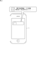
- FIG. 2 is a diagram showing an example of a screen displayed on the information terminal.
- FIG. 3 is an example of a sequence diagram at the time of a demand response among three parties of the server, the HEMS controller, and the power storage device, and a diagram where the demand response can be achieved as scheduled.
- FIG. 4 is another example of a sequence diagram at the time of demand response among three parties of the server, the HEMS controller, and the power storage device, and is a diagram when the demand response can not be achieved.
- FIG. 3 is an example of a sequence diagram at the time of a demand response among three parties of the server, the HEMS controller, and the power storage device, and is a diagram when the demand response can not be achieved.
- FIG. 5 is an example of a sequence diagram at the time of demand response among four persons of temperature / humidity sensor provided in a room where a server, HEMS controller, air conditioner, and air conditioner are installed, and the demand response is on schedule. It is a figure which can be achieved.
- FIG. 6 is another example of the sequence diagram at the time of the demand response between the four parties of the temperature and humidity sensor provided in the server, the HEMS controller, the air conditioner, and the room in which the air conditioner is installed. It is a figure when it can not achieve.
- FIG. 7 is still another example of a sequence diagram at the time of demand response among three parties of the server, the HEMS controller, and the power storage device, and is a diagram when the demand response can not be achieved.
- FIG. 8 is a block diagram schematically showing an internal configuration of the HEMS controller.
- the present disclosure aims to prevent the negative effects of demand response in a consumer and a demand response business company in a preventive manner.
- a transmission unit that transmits a response of participation or non-participation in response to the request, an electric device control unit that controls the electric device, and an information acquisition unit that acquires information of the electric device;
- the energy management apparatus transmits a non-participation response when it is determined that the demand response request can not be achieved after the response transmission.
- Energy management system (2) is an energy management apparatus which is provided in a consumer and can communicate with a server requesting demand response to control the consumer's electrical equipment, and the consumer as one of the electrical equipment.
- An energy management system comprising: a power storage device provided and having a function of transmitting information indicating a power storage state of itself and providing the energy management device with the energy management device, wherein the energy management device is a request for demand response from the server
- a receiver for receiving a request, a transmitter for transmitting a response to participation or non-participation in response to the request, an electric device control unit for controlling the electric device, and an information acquisition portion for acquiring information of the electric device And transmitting information on the state of charge of the electric storage device after transmitting the response to the participation, and requesting the demand response based on the acquired information. Sending a response not participate when it is determined that can not be achieved, the energy management system.
- the energy management apparatus can not achieve the request for demand response due to a change in the state of charge thereafter. If so, the energy management apparatus can send a non-participation response to cancel the demand response. According to such an energy management system, it is possible to prevent the negative effects of the demand response in the consumer and the demand response business operator in a preventive manner.
- this is an energy management system provided with a server which requests demand response, and an energy management apparatus which is provided to a consumer and can communicate with the server to control the electrical equipment of the consumer.
- the energy management apparatus includes a receiving unit that receives a request for a demand response from the server, a transmitting unit that transmits a response to participation or non-participation in response to the request, and an electric device control unit that controls the electric device.
- An information acquisition unit for acquiring information on the electrical device, the information on the electrical device being acquired after transmission of the response to the participation, and the request for the demand response can not be achieved based on the acquired information
- It is an energy management system that sends a nonparticipation response when it makes a decision.
- the energy management apparatus even if the energy management apparatus receives a request for demand response and once transmits a response for participation, it can not achieve the request for demand response due to a change in the state of charge thereafter. If so, the energy management apparatus can send a non-participation response to cancel the demand response. In this case, the server sends a demand response request to the energy management device of another customer. According to such an energy management system, it is possible to prevent the negative effects of the demand response in the consumer and the demand response business operator in a preventive manner.
- the energy management system of (3) includes an information terminal capable of communicating with the energy management apparatus, and the energy management apparatus has a function of receiving the setting of the electric device from the information terminal. It may be.
- the electric device to be controlled is, for example, an air conditioner
- the user of the energy management apparatus can set the temperature setting of the air conditioner to an arbitrary value from the information terminal.
- the energy management apparatus can determine, based on the temperature setting, whether or not to participate in the demand response, and if it participates, whether or not to continue the subsequent participation.
- the energy management apparatus notifies the information terminal that the request has been received from the energy management system, and receives an instruction for participation or non-participation from the information terminal. It may be to respond to the server. In this case, the energy management apparatus determines whether or not to participate in the demand response and, if it participates, whether or not to continue the subsequent participation, in addition to the determination based on the logic set in itself, the user's optional Decisions based on instructions can also be performed.
- Energy management method (6) is an energy management that is executed between the server that requests demand response and the energy management device that is provided to the customer and that can communicate with the server to control the electric equipment of the customer.
- the server transmits a request for a demand response to the energy management apparatus, and the energy management apparatus capable of the demand response upon receiving the request transmits a response for participation, and the participation is performed.
- the energy management apparatus acquires the information of the electric device, and transmits the non-participation response when judging that the request for the demand response can not be achieved based on the acquired information.
- Request for demand response from energy management devices of other customers when the non-participation response is received To send, is also the energy management methods.
- the energy management apparatus even if the energy management apparatus receives a request for demand response and once transmits a response for participation, it can not achieve the request for demand response due to a change in the state of charge thereafter. If so, the energy management apparatus can send a non-participation response to cancel the demand response. In this case, the server sends a demand response request to the energy management device of another customer. According to such an energy management method, it is possible to prevent the negative effects of the demand response in the consumer and the demand response business operator in a preventive manner.
- FIG. 1 is a diagram showing an example of a system configuration of an energy management system.
- the energy management system 100 mainly includes an HEMS (Home Energy Management System) controller 1 as an "energy management apparatus" provided in the customer 10, various electric devices of the customer 10, and a server for requesting a demand response. It is comprised by two.
- HEMS Home Energy Management System
- the HEMS controller 1 is a device also called an HEMS gateway, includes a computer and a storage device (not shown), and realizes necessary functions by causing a computer to execute software (computer program).
- the software is stored in a storage device.
- Examples of electric devices of the customer 10 include a power storage device 3, a television 4, an air conditioner 5, a lighting fixture 6 and the like, and the HEMS controller 1 communicates the electric devices using a common home network communication standard. , Can be monitored and controlled. As such a communication standard, for example, the Echonet Lite (ECHONET Lite) standard is considered.
- ECHONET Lite Echonet Lite
- the storage device 3 can be an electric vehicle (EV) or a plug-in hybrid vehicle (PHV) as well as a dedicated fixed storage device.
- EV electric vehicle
- PSV plug-in hybrid vehicle
- power storage device 3 can reduce power purchase from the commercial power system by discharging the power stored in the built-in storage battery and covering at least a part of the load in the customer. Discharge of a storage battery brings about a big power consumption control effect, when it sees from a commercial power system side in a small-sized consumer like a general household.
- the air conditioner 5 with relatively large power consumption can save power by reducing the intensity of cooling or heating.
- the television 4 can save power by, for example, setting the energy saving mode to reduce the brightness of the screen to an extent that causes no hindrance.
- the lighting fixture 6 can save power by lowering the brightness if it can be adjusted.
- the HEMS controller 1 can communicate with the server 2 via the Internet line. Moreover, the HEMS controller 1 can communicate with the information terminal 7 of the user who is a resident of the customer 10 via the internet circuit.
- the information terminal 7 is typically a smartphone, in which a HEMS application necessary for communication with the HEMS controller 1 is installed.
- Example of demand response In the energy management system 100 configured as described above, when there is a request for a demand response from the server 2, the HEMS controller 1 that has received the request notifies the information terminal 7 that the request has been received as a "push notification”. .
- FIG. 2 is a diagram showing an example of a screen displayed on the information terminal 7.
- the information terminal 7 displays, as a demand response request, for example, "A request for cooperation to reduce the power has been made. Please reply to participation or non-participation.”
- the user carrying the information terminal 7 can indicate the participation or non-participation intention.
- the indication of participation in or non-participation in the demand response reaches the HEMS controller 1.
- the HEMS controller 1 responds to the server 2 about participation or non-participation in the demand response.
- the HEMS controller 1 itself may be configured to determine whether to receive a request for a demand response based on a logic set in itself.
- power saving by the air conditioner 5 is directly linked to the comfort of the user, it may be preferable in some cases to enable determination based on any instruction of the user.
- the HEMS controller 1 in the case of responding to participation in the demand response controls the electric equipment of the customer 10 and performs power saving of commercial power for a certain period. After a certain period of time has elapsed, the HEMS controller 1 controls the electrical equipment of the customer 10 to restore the original state before the start of power saving.
- FIG. 3 is an example of a sequence diagram at the time of a demand response among three parties of the server 2, the HEMS controller 1, and the power storage device 3, and a diagram in the case where the demand response can be achieved as scheduled.
- the server 2 requests the HEMS controller 1 for a demand response (step S1).
- the HEMS controller 1 having received the request determines that participation in the demand response is possible based on the result of monitoring the remaining amount of the power storage device 3 (step S2), and responds to the server 2 of participation (OptIn) (step S3).
- the server 2 of participation OptIn
- the HEMS controller 1 that has made a response to participation controls the power storage device 3 to the state of “discharge” at the start of the demand response notified from the server 2 (step S4).
- the HEMS controller 1 monitors the operating state of the power storage device 3 during the demand response period (step S5), and replies that the power storage device 3 is being discharged.
- step S6 the HEMS controller 1 controls the power storage device 3 to stop discharging (step S7).
- step S7 the requested demand response request can be achieved.
- FIG. 4 is another example of the sequence diagram at the time of the demand response among the three parties of the server 2, the HEMS controller 1, and the power storage device 3, and is a diagram when the demand response can not be achieved. .
- the server 2 requests the HEMS controller 1 for a demand response (step S1).
- the HEMS controller 1 having received the request determines that participation in the demand response is possible based on the result of monitoring the remaining amount of the power storage device 3 (step S2), and responds to the server 2 of participation (OptIn) (step S3).
- the server 2 of participation OptIn
- the HEMS controller 1 that has made a response to participation controls the power storage device 3 to the state of “discharge” at the start of the demand response notified from the server 2 (step S4).
- the HEMS controller 1 monitors the operating state of the power storage device 3 during the demand response period (step S5), and replies that the power storage device 3 is being discharged.
- Step S6 the HEMS controller 1 recognizes that the discharge has been stopped by the monitor and the response of discharge stop (step S7), and determines that the requested demand response request can not be achieved, and the server 2 does not participate (OptOut). A response is made (step S8).
- the energy management system 100 including the HEMS controller 1 or the power storage device 3 and the HEMS controller 1, even when a request for a demand response is received and a response is made once, the storage state is thereafter obtained.
- the demand response request due to the change of, it is possible to cancel the demand response response by responding to the non-participation.
- the server 2 having received the non-participation response makes a request for demand response to the HEMS controller 1 of another customer. Even if the demand response can not be achieved, if the server 2 is not notified of this, the server 2 can not take the next action or the response will be delayed.
- the server 2 that receives a non-participation response requests demand response from the energy management apparatuses of other customers, thereby making a demand response.
- the demand response can be realized for the whole area, determining the place of the demander who receives the request of
- FIG. 5 is an example of a sequence diagram at the time of a demand response among four persons of the temperature / humidity sensor 8 provided in the room where the server 2, the HEMS controller 1, the air conditioner 5, and the air conditioner 5 are installed. It is a figure when demand response can be achieved as scheduled.
- the HEMS controller 1 monitors the operating condition of the air conditioner 5, and it is assumed that the air conditioner 5 is currently operating. Further, an allowable room temperature is set from the information terminal 7 to the HEMS controller 1.
- the allowable room temperature is the room temperature at the upper limit or the lower limit that can be tolerated by the person in the room where the air conditioner 5 is installed.
- the server 2 requests the HEMS controller 1 for a demand response (step S1).
- the HEMS controller 1 having received the request determines that the air conditioner 5 is in normal operation and power saving operation is possible, and therefore participation in the demand response is possible (step S2).
- the HEMS controller 1 responds to the server 2 of participation (OptIn) (step S3).
- the air conditioner 5 is already in the power saving operation, the non-participation response is made. In this case, there are no further steps.
- the HEMS controller 1 that has made a response to participation controls the operation of the air conditioner 5 to the state of "power saving mode" at the start of the demand response notified from the server 2 (step S4).
- the HEMS controller 1 monitors the temperature / humidity sensor 8 during the demand response period to acquire information on room temperature (step S5).
- step S6 the HEMS controller 1 returns the operation mode of the air conditioner 5 to the "normal mode" before the demand response period (step S7).
- the requested demand response request can be achieved.
- FIG. 6 is another example of a sequence diagram at the time of a demand response among four persons of the temperature / humidity sensor 8 provided in the room in which the server 2, the HEMS controller 1, the air conditioner 5, and the air conditioner 5 are installed. It is a figure when demand response can not be achieved.
- the HEMS controller 1 monitors the operating condition of the air conditioner 5, and it is assumed that the air conditioner 5 is currently operating. Further, an allowable room temperature is set from the information terminal 7 to the HEMS controller 1.
- the allowable room temperature is the room temperature at the upper limit or the lower limit that can be tolerated by the person in the room where the air conditioner 5 is installed.
- the server 2 requests the HEMS controller 1 for a demand response (step S1).
- the HEMS controller 1 having received the request determines that the air conditioner 5 is in normal operation and power saving operation is possible, and therefore participation in the demand response is possible (step S2).
- the HEMS controller 1 responds to the server 2 of participation (OptIn) (step S3).
- the air conditioner 5 is already in the power saving operation, the non-participation response is made. In this case, there are no further steps.
- the HEMS controller 1 that has made a response to participation controls the operation of the air conditioner 5 to the state of "power saving mode" at the start of the demand response notified from the server 2 (step S4).
- the HEMS controller 1 monitors the temperature / humidity sensor 8 during the demand response period to acquire information on room temperature (step S5).
- step S6 the HEMS controller 1 determines that the required demand response request can not be achieved and does not participate ( A response of OptOut is made (step S7). Thereafter, the HEMS controller 1 returns the air conditioner 5 from the power saving mode to the normal mode (step S8).
- the limit value of humidity may be set to execute the power saving mode of the dehumidifying operation.
- the energy management system 100 including the HEMS controller 1 or the power storage device 3 and the HEMS controller 1, even if a request for a demand response is received and a response is made once, the allowable room temperature is thereafter set. If the demand response request can not be achieved, the non-participation response can be made to cancel the demand response response.
- the server 2 having received the non-participation response makes a request for demand response to the HEMS controller 1 of another customer.
- the server 2 that receives a non-participation response requests demand response from the energy management apparatuses of other customers, thereby making a demand response.
- the demand response can be realized for the whole area, determining the place of the demander who receives the request of
- FIG. 7 is still another example of a sequence diagram at the time of a demand response among three parties of the server 2, the HEMS controller 1, and the power storage device 3, and a diagram when the demand response can not be achieved.
- the server 2 requests the HEMS controller 1 for a demand response (step S1). This request is not power saving but consumption (storage).
- the HEMS controller 1 having received the request determines that participation in the demand response is possible (rechargeable) from the result of monitoring the remaining amount of the power storage device 3 (step S2), and responds to the server 2 of participation (OptIn). (Step S3).
- the electrical storage apparatus 3 is fully charged and can not be further charged, a non-participation response is made. In this case, there are no further steps.
- the HEMS controller 1 that has made a response to participation controls the power storage device 3 to be in the state of “charging” at the start of the demand response notified from the server 2 (step S4).
- the HEMS controller 1 monitors the operating state of the power storage device 3 during the demand response period (step S5), and replies that the power storage device 3 is charging.
- Step S6 The HEMS controller 1 recognizes that the charge has been stopped by the monitor and the response of the discharge stop (step S7), and determines that the requested demand response request can not be achieved, and does not participate in the server 2 (OptOut). Response (step S8).
- the energy management system 100 including the HEMS controller 1 or the power storage device 3 and the HEMS controller 1, even when a request for a demand response is received and a response is made once, the storage state is thereafter obtained.
- the demand response request due to the change of, it is possible to cancel the demand response response by responding to the non-participation.
- the server 2 that has received the non-participation response makes a demand response request to the HEMS controller 1 of another customer, as in the case of the power suppression. That is, the server 2 having received the non-participation response determines the demand response request from the energy management apparatus of the other customers, thereby determining the substitute for the demand response request consumer, and as a whole, Demand response can be realized.
- FIG. 8 is a block diagram schematically showing the internal configuration of the HEMS controller 1.
- the HEMS controller 1 includes, for example, a central processing unit (CPU) 1 c, a transmission unit 1 t, a reception unit 1 r, and a storage unit 1 m.
- the CPU 1c includes, for example, an electric device control unit C1, an information acquisition unit C2, and an information determination unit C3 as functional units achieved by the computer program stored in the storage unit 1m.
- the electric device control unit C1 can transmit a signal for controlling the electric device of the customer from the transmission unit 1t.
- the information acquisition unit C2 can acquire the information of the electric equipment of the customer via the reception unit 1r. Further, regarding the demand response, the reception unit 1 r receives the request for the demand response from the server 2.
- the transmission unit 1t determines the demand response request by the CPU 1c, and transmits a participation or non-participation response.
- Such a HEMS controller (in particular, the information acquisition unit C2 and the information determination unit C3) 1 can transmit a non-participation response when it determines that the demand response request can not be achieved after transmission of the participation response.
- the server 2, the energy management device 1, and the information terminal 7 described above are computers configured of a CPU, a read only memory (ROM), a random access memory (RAM), a hard disk drive (HDD), and the like. It may be configured as a system.
- a computer program is stored in the RAM or the HDD. Each device achieves its function by the CPU operating according to the computer program.
- the computer program is configured by combining a plurality of instruction codes indicating instructions to the computer in order to achieve a predetermined function.
- the system LSI is a super-multifunctional LSI manufactured by integrating a plurality of components on one chip, and more specifically, is a computer system including a CPU, a ROM, a RAM, and the like. A computer program is stored in the RAM. The system LSI achieves its functions by the CPU operating according to the computer program.
- the present disclosure may be the method described above.
- the present disclosure may be a computer program that implements these methods by a computer.
- the computer program may be recorded in a computer readable non-transitory recording medium, such as an HDD, a CD-ROM, a semiconductor memory, and the like.
- the present disclosure may transmit the computer program via a telecommunication line, a wireless or wired communication line, a network represented by the Internet, data broadcasting, and the like. Further, each of the above-described devices may be realized by a plurality of computers.
- some or all of the functions of the above-described devices may be provided by cloud computing. That is, some or all of the functions of each device may be realized by the cloud server. Furthermore, the above embodiment and the above modification may be combined respectively.
Landscapes
- Engineering & Computer Science (AREA)
- Power Engineering (AREA)
- Physics & Mathematics (AREA)
- General Physics & Mathematics (AREA)
- Automation & Control Theory (AREA)
- Remote Monitoring And Control Of Power-Distribution Networks (AREA)
- Supply And Distribution Of Alternating Current (AREA)
Abstract
La présente invention concerne un dispositif de gestion d'énergie, lequel est fourni à un consommateur et peut contrôler un équipement électrique du consommateur en communiquant avec un serveur requérant une réponse à une demande, qui comporte : une unité de réception destinée à recevoir une requête d'une réponse à une demande du serveur ; une unité de transmission destinée à transmettre une réponse de participation ou de non-participation par rapport à la requête ; une unité de contrôle d'équipement électrique destinée à contrôler l'équipement électrique ; et une unité d'acquisition d'informations destinée à acquérir des informations concernant l'équipement électrique, et qui transmet une réponse de non-participation lorsqu'il est déterminé, après la transmission d'une réponse de participation, que la requête d'une réponse à une demande ne peut être satisfaite.
Priority Applications (3)
| Application Number | Priority Date | Filing Date | Title |
|---|---|---|---|
| EP18870049.6A EP3703221A4 (fr) | 2017-10-23 | 2018-05-11 | Dispositif de gestion d'énergie, système de gestion d'énergie, et procédé de gestion d'énergie |
| US16/754,691 US11502518B2 (en) | 2017-10-23 | 2018-05-11 | Energy management device, energy management system, and energy management method |
| JP2019549827A JPWO2019082426A1 (ja) | 2017-10-23 | 2018-05-11 | エネルギー管理装置、エネルギー管理システム、及び、エネルギー管理方法 |
Applications Claiming Priority (2)
| Application Number | Priority Date | Filing Date | Title |
|---|---|---|---|
| JP2017-204618 | 2017-10-23 | ||
| JP2017204618 | 2017-10-23 |
Publications (1)
| Publication Number | Publication Date |
|---|---|
| WO2019082426A1 true WO2019082426A1 (fr) | 2019-05-02 |
Family
ID=66246331
Family Applications (1)
| Application Number | Title | Priority Date | Filing Date |
|---|---|---|---|
| PCT/JP2018/018347 Ceased WO2019082426A1 (fr) | 2017-10-23 | 2018-05-11 | Dispositif de gestion d'énergie, système de gestion d'énergie, et procédé de gestion d'énergie |
Country Status (4)
| Country | Link |
|---|---|
| US (1) | US11502518B2 (fr) |
| EP (1) | EP3703221A4 (fr) |
| JP (1) | JPWO2019082426A1 (fr) |
| WO (1) | WO2019082426A1 (fr) |
Cited By (2)
| Publication number | Priority date | Publication date | Assignee | Title |
|---|---|---|---|---|
| EP3964385A1 (fr) | 2020-09-04 | 2022-03-09 | Toyota Jidosha Kabushiki Kaisha | Dispositif de commande de véhicule, support de stockage non-transitoire dans un ordinateur de gestion de réseau électrique et procédé de commande de verrouillage de connecteur |
| WO2023074149A1 (fr) * | 2021-10-26 | 2023-05-04 | 株式会社Nttドコモ | Système de commande de puissance |
Families Citing this family (3)
| Publication number | Priority date | Publication date | Assignee | Title |
|---|---|---|---|---|
| JP7233964B2 (ja) * | 2019-02-26 | 2023-03-07 | 三菱重工業株式会社 | 運転指標提示装置、運転指標提示方法、およびプログラム |
| US11495993B1 (en) * | 2021-05-11 | 2022-11-08 | Kitu Systems, Inc. | System and method for facilitating autonomous operation of a smart energy device |
| CA3165093A1 (fr) * | 2021-06-30 | 2022-12-30 | Marshall Group Enterprises Inc. | Systemes, appareil et methodes pour la telecommande de plusieurs dispositifs de chauffage |
Citations (8)
| Publication number | Priority date | Publication date | Assignee | Title |
|---|---|---|---|---|
| JP2009247188A (ja) * | 2008-03-31 | 2009-10-22 | Osaka Gas Co Ltd | 電力デマンド制御システム |
| JP2015226434A (ja) * | 2014-05-29 | 2015-12-14 | 住友電気工業株式会社 | 電力消費管理装置、電力消費管理システム、電力消費管理方法および電力消費管理プログラム |
| JP2017011793A (ja) * | 2015-06-17 | 2017-01-12 | パナソニックIpマネジメント株式会社 | 管理装置、管理方法、及び管理用プログラム |
| WO2017018530A1 (fr) * | 2015-07-30 | 2017-02-02 | 日本電気株式会社 | Système de traitement d'informations, procédé de traitement d'informations, et programme |
| JP2017038469A (ja) | 2015-08-10 | 2017-02-16 | 住友電気工業株式会社 | 需要家装置、電力消費管理方法および電力消費管理プログラム |
| JP2017112646A (ja) * | 2015-12-14 | 2017-06-22 | 三菱電機株式会社 | 需給調整装置、需給調整システムおよびエネルギー需給調整方法 |
| JP2017184461A (ja) * | 2016-03-30 | 2017-10-05 | 株式会社デンソー | 電力管理システム及び電力制御装置 |
| JP2017204618A (ja) | 2016-05-13 | 2017-11-16 | 株式会社リコー | 面発光レーザ素子、面発光レーザアレイ、画像形成装置、画像表示装置、レーザ加工機、レーザアニール装置、点火装置及び面発光レーザ素子の製造方法。 |
Family Cites Families (14)
| Publication number | Priority date | Publication date | Assignee | Title |
|---|---|---|---|---|
| US8843242B2 (en) * | 2008-09-15 | 2014-09-23 | General Electric Company | System and method for minimizing consumer impact during demand responses |
| US9838255B2 (en) * | 2009-08-21 | 2017-12-05 | Samsung Electronics Co., Ltd. | Mobile demand response energy management system with proximity control |
| US20130054863A1 (en) * | 2011-08-30 | 2013-02-28 | Allure Energy, Inc. | Resource Manager, System And Method For Communicating Resource Management Information For Smart Energy And Media Resources |
| US9807099B2 (en) * | 2013-03-15 | 2017-10-31 | Google Inc. | Utility portals for managing demand-response events |
| US9098876B2 (en) * | 2013-05-06 | 2015-08-04 | Viridity Energy, Inc. | Facilitating revenue generation from wholesale electricity markets based on a self-tuning energy asset model |
| US9852484B1 (en) * | 2014-02-07 | 2017-12-26 | Opower, Inc. | Providing demand response participation |
| JP2016001987A (ja) * | 2014-05-22 | 2016-01-07 | パナソニックIpマネジメント株式会社 | デマンドレスポンス制御方法、および、デマンドレスポンス制御装置 |
| CN107078542B (zh) * | 2014-11-04 | 2020-08-18 | 三菱电机株式会社 | 控制器以及控制方法 |
| EP3226369A4 (fr) * | 2014-11-27 | 2018-08-01 | Kyocera Corporation | Dispositif de régulation d'énergie, procédé de régulation d'énergie et programme de régulation d'énergie |
| US20180267701A1 (en) * | 2015-09-11 | 2018-09-20 | Johnson Controls Technology Company | Thermostat with customizable user interfaces |
| JP6653153B2 (ja) * | 2015-10-01 | 2020-02-26 | 株式会社日立製作所 | 電力需要調整計画管理装置 |
| WO2017098631A1 (fr) * | 2015-12-10 | 2017-06-15 | 三菱電機株式会社 | Dispositif régulateur d'énergie, procédé d'élaboration de plans d'exploitation, et programme |
| KR20180077431A (ko) * | 2016-12-29 | 2018-07-09 | 주식회사 인코어드 테크놀로지스 | 전력수요 관리 기능을 갖는 서버, 가전기기, 및 그것의 전력 사용 관리 방법 |
| US11022947B2 (en) * | 2017-06-07 | 2021-06-01 | Johnson Controls Technology Company | Building energy optimization system with economic load demand response (ELDR) optimization and ELDR user interfaces |
-
2018
- 2018-05-11 EP EP18870049.6A patent/EP3703221A4/fr active Pending
- 2018-05-11 JP JP2019549827A patent/JPWO2019082426A1/ja active Pending
- 2018-05-11 WO PCT/JP2018/018347 patent/WO2019082426A1/fr not_active Ceased
- 2018-05-11 US US16/754,691 patent/US11502518B2/en active Active
Patent Citations (8)
| Publication number | Priority date | Publication date | Assignee | Title |
|---|---|---|---|---|
| JP2009247188A (ja) * | 2008-03-31 | 2009-10-22 | Osaka Gas Co Ltd | 電力デマンド制御システム |
| JP2015226434A (ja) * | 2014-05-29 | 2015-12-14 | 住友電気工業株式会社 | 電力消費管理装置、電力消費管理システム、電力消費管理方法および電力消費管理プログラム |
| JP2017011793A (ja) * | 2015-06-17 | 2017-01-12 | パナソニックIpマネジメント株式会社 | 管理装置、管理方法、及び管理用プログラム |
| WO2017018530A1 (fr) * | 2015-07-30 | 2017-02-02 | 日本電気株式会社 | Système de traitement d'informations, procédé de traitement d'informations, et programme |
| JP2017038469A (ja) | 2015-08-10 | 2017-02-16 | 住友電気工業株式会社 | 需要家装置、電力消費管理方法および電力消費管理プログラム |
| JP2017112646A (ja) * | 2015-12-14 | 2017-06-22 | 三菱電機株式会社 | 需給調整装置、需給調整システムおよびエネルギー需給調整方法 |
| JP2017184461A (ja) * | 2016-03-30 | 2017-10-05 | 株式会社デンソー | 電力管理システム及び電力制御装置 |
| JP2017204618A (ja) | 2016-05-13 | 2017-11-16 | 株式会社リコー | 面発光レーザ素子、面発光レーザアレイ、画像形成装置、画像表示装置、レーザ加工機、レーザアニール装置、点火装置及び面発光レーザ素子の製造方法。 |
Non-Patent Citations (1)
| Title |
|---|
| See also references of EP3703221A4 |
Cited By (3)
| Publication number | Priority date | Publication date | Assignee | Title |
|---|---|---|---|---|
| EP3964385A1 (fr) | 2020-09-04 | 2022-03-09 | Toyota Jidosha Kabushiki Kaisha | Dispositif de commande de véhicule, support de stockage non-transitoire dans un ordinateur de gestion de réseau électrique et procédé de commande de verrouillage de connecteur |
| US12059970B2 (en) | 2020-09-04 | 2024-08-13 | Toyota Jidosha Kabushiki Kaisha | Vehicle control device, non-transitory storage medium in management computer for power grid, and connector locking control method |
| WO2023074149A1 (fr) * | 2021-10-26 | 2023-05-04 | 株式会社Nttドコモ | Système de commande de puissance |
Also Published As
| Publication number | Publication date |
|---|---|
| EP3703221A4 (fr) | 2021-06-16 |
| EP3703221A1 (fr) | 2020-09-02 |
| US20210200175A1 (en) | 2021-07-01 |
| US11502518B2 (en) | 2022-11-15 |
| JPWO2019082426A1 (ja) | 2020-11-12 |
Similar Documents
| Publication | Publication Date | Title |
|---|---|---|
| WO2019082426A1 (fr) | Dispositif de gestion d'énergie, système de gestion d'énergie, et procédé de gestion d'énergie | |
| JP2013098672A (ja) | 制御装置及び制御対象機器 | |
| EP2903216B1 (fr) | Système de gestion, procédé de gestion et dispositif | |
| JP5952416B2 (ja) | 管理方法、制御装置及び通信処理デバイス | |
| JP6414456B2 (ja) | 需要家装置、電力消費管理装置、電力消費管理システム、電力消費管理方法および電力消費管理プログラム | |
| US20190157877A1 (en) | Management method, management device, distributed power supply, and management system | |
| JP5439424B2 (ja) | 制御装置 | |
| JP2016220488A (ja) | 需要家通信装置、需要家通信方法及び需要家通信システム | |
| JP2005033952A (ja) | 電力需給管理システム、電力需給管理方法及び電力需給管理プログラム | |
| US20190157866A1 (en) | Power management apparatus, power management method, and power management system | |
| JP6021088B2 (ja) | 負荷制御方法、負荷制御装置、及び、電気負荷装置 | |
| JP6802833B2 (ja) | 管理システム、管理方法、操作端末及び制御装置 | |
| JP5967543B2 (ja) | コントローラ、電力管理システムおよびプログラム | |
| US10530183B2 (en) | Communication apparatus, power management apparatus, and power management method | |
| JP2018201282A (ja) | 通信装置、及び通信システム | |
| JP5632415B2 (ja) | 制御機器、及び制御方法 | |
| WO2015115571A1 (fr) | Dispositif de commande et procédé de commande | |
| US20180317175A1 (en) | Method for securing availability of mobile terminal device and information processing device | |
| JP6376379B2 (ja) | 電力管理装置 | |
| JPWO2017018344A1 (ja) | 通信装置及び通信方法 | |
| JP2017005787A (ja) | エネルギー管理システム | |
| JP6631870B2 (ja) | 電力管理システム、電力管理装置、電力管理方法、及び、プログラム | |
| US20220255321A1 (en) | Server apparatus and management method | |
| JP6467108B2 (ja) | 管理システム、管理方法、機器及び制御装置 | |
| JP2018085920A (ja) | エネルギー管理システム、エネルギー管理装置、端末及びエネルギー管理方法 |
Legal Events
| Date | Code | Title | Description |
|---|---|---|---|
| 121 | Ep: the epo has been informed by wipo that ep was designated in this application |
Ref document number: 18870049 Country of ref document: EP Kind code of ref document: A1 |
|
| ENP | Entry into the national phase |
Ref document number: 2019549827 Country of ref document: JP Kind code of ref document: A |
|
| NENP | Non-entry into the national phase |
Ref country code: DE |
|
| ENP | Entry into the national phase |
Ref document number: 2018870049 Country of ref document: EP Effective date: 20200525 |