WO2019082731A1 - Organe de connexion électrique - Google Patents
Organe de connexion électriqueInfo
- Publication number
- WO2019082731A1 WO2019082731A1 PCT/JP2018/038441 JP2018038441W WO2019082731A1 WO 2019082731 A1 WO2019082731 A1 WO 2019082731A1 JP 2018038441 W JP2018038441 W JP 2018038441W WO 2019082731 A1 WO2019082731 A1 WO 2019082731A1
- Authority
- WO
- WIPO (PCT)
- Prior art keywords
- bus bars
- connection member
- bus bar
- electrical connection
- pair
- Prior art date
- Legal status (The legal status is an assumption and is not a legal conclusion. Google has not performed a legal analysis and makes no representation as to the accuracy of the status listed.)
- Ceased
Links
Images



Classifications
-
- H—ELECTRICITY
- H01—ELECTRIC ELEMENTS
- H01M—PROCESSES OR MEANS, e.g. BATTERIES, FOR THE DIRECT CONVERSION OF CHEMICAL ENERGY INTO ELECTRICAL ENERGY
- H01M50/00—Constructional details or processes of manufacture of the non-active parts of electrochemical cells other than fuel cells, e.g. hybrid cells
- H01M50/20—Mountings; Secondary casings or frames; Racks, modules or packs; Suspension devices; Shock absorbers; Transport or carrying devices; Holders
- H01M50/204—Racks, modules or packs for multiple batteries or multiple cells
- H01M50/207—Racks, modules or packs for multiple batteries or multiple cells characterised by their shape
- H01M50/209—Racks, modules or packs for multiple batteries or multiple cells characterised by their shape adapted for prismatic or rectangular cells
-
- H—ELECTRICITY
- H01—ELECTRIC ELEMENTS
- H01B—CABLES; CONDUCTORS; INSULATORS; SELECTION OF MATERIALS FOR THEIR CONDUCTIVE, INSULATING OR DIELECTRIC PROPERTIES
- H01B5/00—Non-insulated conductors or conductive bodies characterised by their form
- H01B5/02—Single bars, rods, wires, or strips
-
- H—ELECTRICITY
- H01—ELECTRIC ELEMENTS
- H01M—PROCESSES OR MEANS, e.g. BATTERIES, FOR THE DIRECT CONVERSION OF CHEMICAL ENERGY INTO ELECTRICAL ENERGY
- H01M50/00—Constructional details or processes of manufacture of the non-active parts of electrochemical cells other than fuel cells, e.g. hybrid cells
- H01M50/50—Current conducting connections for cells or batteries
-
- H—ELECTRICITY
- H01—ELECTRIC ELEMENTS
- H01R—ELECTRICALLY-CONDUCTIVE CONNECTIONS; STRUCTURAL ASSOCIATIONS OF A PLURALITY OF MUTUALLY-INSULATED ELECTRICAL CONNECTING ELEMENTS; COUPLING DEVICES; CURRENT COLLECTORS
- H01R11/00—Individual connecting elements providing two or more spaced connecting locations for conductive members which are, or may be, thereby interconnected, e.g. end pieces for wires or cables supported by the wire or cable and having means for facilitating electrical connection to some other wire, terminal, or conductive member, blocks of binding posts
- H01R11/01—Individual connecting elements providing two or more spaced connecting locations for conductive members which are, or may be, thereby interconnected, e.g. end pieces for wires or cables supported by the wire or cable and having means for facilitating electrical connection to some other wire, terminal, or conductive member, blocks of binding posts characterised by the form or arrangement of the conductive interconnection between the connecting locations
-
- H—ELECTRICITY
- H01—ELECTRIC ELEMENTS
- H01R—ELECTRICALLY-CONDUCTIVE CONNECTIONS; STRUCTURAL ASSOCIATIONS OF A PLURALITY OF MUTUALLY-INSULATED ELECTRICAL CONNECTING ELEMENTS; COUPLING DEVICES; CURRENT COLLECTORS
- H01R4/00—Electrically-conductive connections between two or more conductive members in direct contact, i.e. touching one another; Means for effecting or maintaining such contact; Electrically-conductive connections having two or more spaced connecting locations for conductors and using contact members penetrating insulation
- H01R4/58—Electrically-conductive connections between two or more conductive members in direct contact, i.e. touching one another; Means for effecting or maintaining such contact; Electrically-conductive connections having two or more spaced connecting locations for conductors and using contact members penetrating insulation characterised by the form or material of the contacting members
-
- H—ELECTRICITY
- H01—ELECTRIC ELEMENTS
- H01R—ELECTRICALLY-CONDUCTIVE CONNECTIONS; STRUCTURAL ASSOCIATIONS OF A PLURALITY OF MUTUALLY-INSULATED ELECTRICAL CONNECTING ELEMENTS; COUPLING DEVICES; CURRENT COLLECTORS
- H01R9/00—Structural associations of a plurality of mutually-insulated electrical connecting elements, e.g. terminal strips or terminal blocks; Terminals or binding posts mounted upon a base or in a case; Bases therefor
- H01R9/03—Connectors arranged to contact a plurality of the conductors of a multiconductor cable, e.g. tapping connections
-
- Y—GENERAL TAGGING OF NEW TECHNOLOGICAL DEVELOPMENTS; GENERAL TAGGING OF CROSS-SECTIONAL TECHNOLOGIES SPANNING OVER SEVERAL SECTIONS OF THE IPC; TECHNICAL SUBJECTS COVERED BY FORMER USPC CROSS-REFERENCE ART COLLECTIONS [XRACs] AND DIGESTS
- Y02—TECHNOLOGIES OR APPLICATIONS FOR MITIGATION OR ADAPTATION AGAINST CLIMATE CHANGE
- Y02E—REDUCTION OF GREENHOUSE GAS [GHG] EMISSIONS, RELATED TO ENERGY GENERATION, TRANSMISSION OR DISTRIBUTION
- Y02E60/00—Enabling technologies; Technologies with a potential or indirect contribution to GHG emissions mitigation
- Y02E60/10—Energy storage using batteries
Definitions
- the technology disclosed herein relates to an electrical connection member that connects terminals, and more particularly to an electrical connection member that includes a plurality of flexible bus bars.
- Patent Document 1 shows an example using a metal stranded wire and a multilayer metal sheet as a plurality of flexible conductive members.
- Patent Document 1 when the metal stranded wire or the metal sheet is twisted or when the metal stranded wire or the metal sheet is bent, a gap is generated between the strands or between the metal sheets. In some cases, the gap may become large or not be restored. In this case, the wire and the metal sheet are separated in the electrically insulated state by the generated gap. At that time, it is conceivable that different portions of the current flowing between the separated conductive members are generated due to the nonuniformity of the resistance value inside each conductive member and the like.
- the conductive member in general, it is difficult to manufacture the conductive member by making the resistance value of the conductive member completely uniform over the entire area of the conductive member, for example, resistance in the conductive member due to nonuniformity such as thickness of the conductive member. There is a distribution of values. In other words, due to manufacturing tolerances (acceptable tolerances) of the conductive members, a difference in resistance exists between the conductive members.
- the technology disclosed in the present specification provides an electrical connection member that can reduce variation in heat distribution among the bus bars in the electrical connection member including a plurality of flexible bus bars (conductive members).
- the electrical connection member disclosed in the present specification is an electrical connection member that electrically connects terminals via a terminal connection portion, and is a pair of electrical connection members formed at both ends and electrically connected to the terminal connection portion.
- the inter-bus bar connection portion that electrically connects the plurality of bus bars including the flexible portion is provided between the pair of joint portions. Therefore, each bus bar is electrically connected between the pair of joints.
- the electrically connectable material that is, the conductive material has good thermal conductivity and has a function of heat diffusion and heat dissipation.
- bus bars due to the distribution of resistance values in the bus bars, various current value differences occur between the bus bars, and even if there is a difference in the amount of heat generation between the bus bars, the bus bars have good thermal conductivity
- the heat generated at the bus bars is dispersed between the bus bars by the connection portion. Thereby, the variation in heat distribution between the bus bars can be reduced.
- the bus bar connection portion may be provided at a central point of a length between the pair of joint portions of each of the plurality of bus bars.
- the bus bar connection portion may be provided at a central point of a length between the pair of joint portions of each of the plurality of bus bars.
- the bus bar connection portion connects the plurality of bus bars in a state where the plurality of bus bars are erected such that the width direction of each bus bar of the plurality of bus bars is a vertical direction. You may According to this configuration, the bus bars are connected by the inter-bus-bar connection portion in a state where the bus bars stand upright such that the width direction is the vertical direction. Therefore, even in the case where the electrical connection member includes a plurality of bus bars, the size of the entire electrical connection member can be made more compact than in the case where each bus bar is laid down.
- the bus bar connection portion may connect the plurality of bus bars at at least one of the upper end portion and the lower end portion in the width direction of the plurality of bus bars.
- the bus bar connection portion since the bus bar connection portion is configured to be connected to the bus bar at the end portion in the width direction of the bus bar, the bus bar connection portion can be, for example, a plate-like conductive member. The configuration of the connection portion can be simplified.
- the plurality of bus bars include at least three bus bars
- the inter-bus bar connection portion is configured by a plurality of adjacent bus bar connection portions connecting between a pair of adjacent bus bars
- the plurality of adjacent bus bar connecting portions connect the upper adjacent bus bar connecting portion connecting the upper ends in the width direction of the adjacent pair of bus bars, and the lower adjacent bus bar connecting the lower ends in the width direction of the adjacent pair of bus bars
- the connection portion between the upper adjacent bus bars and the connection portion between the lower adjacent bus bars may be alternately provided.
- the adjacent bus bar connection portions are alternately provided between the upper end portion and the lower end portion in the width direction of the bus bar. Therefore, the electrical connection member can be formed from a single metal plate by a cutting operation, a bending operation, or the like.
- the flexible portion may be configured by a bent portion obtained by bending a part of each of the bus bars of the plurality of bus bars in a bellows shape. According to this configuration, the flexible portion can be easily formed by the bending operation of the metal plate.
- the electrical connection member disclosed in the present specification in the electrical connection member including the plurality of flexible bus bars, variation in heat distribution among the bus bars can be reduced.
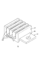
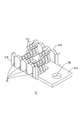
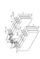
- the perspective view showing the electric connection member concerning one embodiment Front view showing the electrical connection member
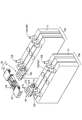
- the perspective view which shows the application example 1 of an electrical connection member The perspective view which shows the cover part of the terminal connection part in the example 1 of application
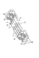
- the perspective view which shows the connection main-body part of the terminal connection part in application example 1 The perspective view which shows the terminal connection part in the application example 2 of an electrical connection member
- the perspective view which shows the joining state of the electric connection member and the cover part of a terminal connection part in application example 2 The perspective view which shows the joining state of the electric connection member and the cover part of a terminal connection part in application example 2
- Embodiment One embodiment of the electrical connection member 10 is described with reference to FIGS. 1-9.
- the electrical connection member 10 is used to electrically connect terminals via a terminal connection.
- the electric connection member 10 is mounted on a vehicle such as an electric vehicle or a hybrid vehicle and used for a battery module (70A, 70B) used as a drive source of the vehicle Ru.
- the electrical connection member 10 roughly includes a plurality of (four in the present embodiment) bus bars 20 and a bus bar connection portion 31.
- the arrow X direction is the longitudinal direction of the bus bar 20
- the arrow Y direction is the line direction of the bus bars 20
- the arrow Z direction is the width direction (vertical direction) of the bus bar 20.
- the plurality of bus bars 20 may include at least three bus bars.
- Each bus bar 20 includes a pair of joint portions (21A, 21B), a flexible portion 22, and a locking portion 23.
- the pair of bonding portions (21A, 21B) are formed at both ends of the bus bar 20 and are electrically bonded to the terminal connection portions 50 described later.
- the tip of each joint (21A, 21B) is a locking portion 23 bent at a right angle.
- the locking portion 23 contacts the wall portion 52B of the cover portion 52 of the terminal connection portion 50 to lock the bus bar 20 to the terminal connection portion 50, as shown in FIG.
- the locking portion 23 also functions as a joint portion to a terminal connection portion 60 described later.
- the flexible portion 22 is provided between the pair of joint portions (21A, 21B), and is configured by a bent portion in which a part of the bus bar 20 is bent in a bellows shape. Therefore, the flexible portion 22 can be easily formed by the bending operation of the metal plate.
- the flexible portion 22 is not limited to the configuration of the bent portion bent in a bellows shape.
- the inter-bus bar connecting portion 31 is provided between the pair of joint portions (21A, 21B), and electrically connects the plurality of bus bars 20.
- the inter-bus bar connecting portion 31 is constituted by a plurality of (three in the present embodiment) adjacent bus-bar connecting portions (31A, 31B) which connect between the pair of adjacent bus bars 20.
- the plurality of adjacent bus bar connections (31A, 31B) connect the upper adjacent bus bars to each other between the upper end portions 24A in the width direction (the arrow Z direction in FIG. 2) of the bus bars 20 for the pair of adjacent bus bars 20.
- a portion 31A and a lower adjacent bus bar connecting portion 31B connecting between lower end portions 24B in the width direction of the bus bar are included.
- the upper adjacent bus bar connection portion 31A and the lower adjacent bus bar connection portion 31B are alternately provided.
- adjacent bus bar connecting portions (31A, 31B) when the upper adjacent bus bar connecting portion 31A and the lower adjacent bus bar connecting portion 31B are not distinguished from one another, they are referred to as adjacent bus bar connecting portions (31A, 31B).
- the two upper adjacent bus bar connecting portions 31 ⁇ / b> A are provided to connect between the upper end portions 24 ⁇ / b> A in the width direction of the bus bar 20.
- the lower adjacent bus bar connecting portion 31B is provided to connect the lower end portions 24B in the width direction of the bus bar 20 between the two upper adjacent bus bar connecting portions 31A.
- the three adjacent bus bar connection portions (31A, 31B) are alternately provided between the upper end 24A and the lower end 24B in the width direction of the bus bar 20. Therefore, the electrical connection member 10 including the three adjacent bus bar connection portions (31A, 31B) can be formed from one metal plate by a cutting operation, a bending operation, or the like.
- the adjacent bus bar connection portion (31A, 31B) is a central point between the pair of joint portions (21A, 21B) between the pair of joint portions (21A, 21B) of each bus bar. It is preferable to be provided at the place where That is, in this case, each of the bus bars 20 is physically connected at the central point of the length between the pair of joints (21 A, 21 B), and compared with the connection at the end of each bus bar 20.
- the heat generated by the bus bar 20 can be effectively dispersed. Therefore, it can be said that the variation in heat distribution can be minimized by the minimum number of adjacent bus bar connections (31A, 31B).
- central point includes not only one point at the central point of the length between a pair of joints but also near points on both sides of the central point. Moreover, in that case, depending on the installation place of the flexible portion 22, the length between the pair of joining portions may or may not include the length of the flexible portion 22.
- each bus bar 20 is electrically connected by the inter-bus bar connecting portion 31 in a state where the width direction of each bus bar 20 is in the vertical direction (Z direction). And mechanically connected. Therefore, even when the electrical connection member 10 includes the plurality of bus bars 20, the overall size (occupied volume) of the electrical connection member 10 can be made compact as compared with the case where each bus bar 20 is laid.
- positioning aspect of each bus-bar 20 is not restricted to this, The structure which lays down each bus-bar 20 and may be arrange
- the inter-bus bar connecting portion 31 is configured to connect the bus bar 20 in a laid state. Note that the state in which the bus bar 20 is laid down means a state in which the plate surface of the bus bar 20 is oriented in the vertical direction.
- each battery module (70A, 70B) includes a plurality of (three in FIG. 3) battery cells 71 having a positive electrode terminal 72A and a negative electrode terminal 72B.
- Each battery cell 71 is disposed such that the positions of the positive electrode terminal 72A and the negative electrode terminal 72B are opposite to each other.
- the adjacent terminal of the adjacent battery cell 71 other than the terminal (positive electrode terminal 72A and negative electrode terminal 72B) connected externally is connected by the electrically-conductive member which is not shown in figure. That is, each battery cell 71 is electrically connected in series.
- the application example of the electrical connection member 10 is not limited to this, and the electrical connection member 10 may be, for example, a connection between the external output positive terminal 72A (OUT) of the battery module 70A and a terminal of an external device, or the external of the battery module 70B. It may be used to connect the output negative terminal 72B (OUT) to a terminal of an external device. Alternatively, the electrical connection member 10 may be used other than the connection of the terminals of the battery module 70.
- Application Example 1 In Application Example 1, as shown in FIG. 3, one end of the electrical connection member 10 is connected to the negative electrode terminal 72B of the battery module 70A via the terminal connection portion 50. Further, the other end of the electrical connection member 10 is connected to the positive electrode terminal 72A of the battery module 70B via the terminal connection portion 50.
- the terminal connection portion 50 includes a connection main body portion 51 and a cover portion 52, as shown in FIG.
- the cover 52 covers the connection main body 51 except for the through hole TH.
- the cover 52 is formed with a notch 52A for inserting the joint (21A, 21B) of each bus bar 20 of the electric connection member 10 and coupling it to the connection main body 51.
- the connection main body portion 51 includes a flat plate portion 51A and wall portions 51B formed on both sides of the flat plate portion 51A, as shown in FIG.
- the flat plate portion 51A is engaged with the through holes TH for coupling the terminal connection portion 50 to the positive electrode terminal 72A or the negative electrode terminal 72B of the battery module 70, and the joint portions (21A, 21B) of the respective bus bars 20 of the electrical connection member 10.
- a locking connection portion 51C for electrically connecting to the flat plate portion 51A is formed.
- Each wall 51B is provided with a slit SL for locking the joint (21A, 21B) of the electrical connection member 10 to the locking connection 51C.
- the joint portions (21A, 21B) of the bus bars 20 of the electric connection member 10 are terminal connection portions. This is performed by sandwiching and connecting the locking connection portion 51C of the flat plate portion 51A through the notch portion 52A of the cover portion 52 of 50.
- Application Example 2 is different from Application Example 1 in the configuration of the terminal connection portion. That is, as shown in FIG. 6, the terminal connection portion 60 of the application example 2 includes the connection main portion 61 and the cover portion 62 similarly to the terminal connection portion 50, but the configurations thereof are different. Moreover, in the application example 2, the connection aspect to the terminal connection part 60 of 10 A of electrical connection members differs from the application example 1.
- FIG. 6 the terminal connection portion 60 of the application example 2 includes the connection main portion 61 and the cover portion 62 similarly to the terminal connection portion 50, but the configurations thereof are different.
- the connection aspect to the terminal connection part 60 of 10 A of electrical connection members differs from the application example 1.
- connection main body portion 61 is constituted by a flat plate portion 61A and a plate-like connection portion 61B vertically erected from the flat plate portion 61A. Similar to the flat plate portion 51A, the flat plate portion 61A is formed with a through hole TH for coupling the terminal connection portion 60 to the positive electrode terminal 72A and the negative electrode terminal 72B of the battery module 70.
- the cover portion 62 is provided with a locking connection portion 62 ⁇ / b> C which is provided on the flat plate portion 51 ⁇ / b> A of the terminal connection portion 50.
- the cover 62 is attached to the connection main body 61 (see FIG. 9), the plate-like connection 61B provided on the connection main body 61 is locked to the locking connection 62C.
- the locking portions 23 of the bus bars 20 of the electrical connection member 10A are coupled to the wall portion 62B of the cover portion 62 by welding, for example.
- Application Example 2 as shown in FIG. 7, the engagement between the bus bars 20 of the electric connection member 10A is performed with the electric connection member 10 of Application Example 1 being reversed in the vertical direction (arrow Z direction in FIG. 1).
- the stop 23 is coupled to the wall 62 B of the cover 62.
- each bus bar 20 functions to join the electric connection member 10A of the bonding portion (21A, 21B) in Application Example 1 to the terminal connection portion.
- the plate-like connection portion 61B of the terminal connection portion 60 corresponds to the bonding portion (21A, 21B) in the application example 1.
- the locking portions 23 of the bus bars 20 of the electrical connection member 10A are connected to the terminal connection portion 60. It is joined to the wall 62 B of the cover 62. Then, the cover portion 62 of the terminal connection portion 60 to which the electrical connection member 10A is joined is attached to the connection main portion 61 connected to the positive electrode terminal 72A or the negative electrode terminal 72B by a nut. At that time, the plate-like connection portion 61B of the connection main body portion 61 is held by and coupled to the locking connection portion 62C of the cover portion 62.
- the inter-bus bar connecting portion 31 that electrically connects the four (plural) bus bars 20 including the flexible portion 22 is provided between the pair of joint portions (21A, 21B). Therefore, each bus bar 20 is electrically connected between the pair of joint portions (21A, 21B).
- the electrically connectable material that is, the conductive material has good thermal conductivity and has a function of heat diffusion and heat dissipation.
- the inter-bus bar connecting portion 31 has a length between the pair of joining portions (21A, 21B) between the pair of joining portions (21A, 21B) of each bus bar.
- the installation location of the connection part 31 between bus bars is not restricted to this.
- it may be provided at a central portion as the bus bar 20, or may be provided at a position adjacent to the flexible portion 22 as shown in FIG.
- the inter-bus bar connecting portion 31 is not limited to one place for each bus bar 20, and may be provided at a plurality of places, for example, three places.
- the installation locations may not be at the same position in the longitudinal direction (the arrow X direction in FIG. 1) of the bus bars 20 in each of the bus bar connection portions 31.
- the inter-bus bar connecting portion 31 is configured by a plurality of (three in the above embodiment) adjacent inter-bus bar connecting portions (31A, 31B) connecting between a pair of adjacent bus bars
- the configuration of the inter-bus bar connecting portion 31 is not limited to this.
- the inter-bus bar connection portion 31 may be configured of a single conductive metal plate that simultaneously connects a plurality of bus bars at the upper end portion or the lower end portion.
- such conductive metal plates may be provided at the upper end and the lower end of the plurality of bus bars.
- the shape of the inter-bus bar connecting portion 31 is not limited to a flat shape. For example, it may be in a partially bent shape.
- connection member 20 bus bar 21A
- 21B pair of joint portions 22: bent portion (flexible portion)
- 31B Lower adjacent busbar connection (inter-busbar connection) 50, 60: Terminal connection
Landscapes
- Chemical & Material Sciences (AREA)
- Chemical Kinetics & Catalysis (AREA)
- Electrochemistry (AREA)
- General Chemical & Material Sciences (AREA)
- Connection Of Batteries Or Terminals (AREA)
- Multi-Conductor Connections (AREA)
- Non-Insulated Conductors (AREA)
- Battery Mounting, Suspending (AREA)
Abstract
La présente invention concerne un organe de connexion électrique (10) qui connecte électriquement une borne d'électrode positive (72A) et une borne d'électrode négative (72B) entre elles par une partie connectrice de bornes (50), l'organe de connexion électrique (10) comportant une pluralité de barres omnibus (20) et des parties d'interconnexion (31) de barres omnibus. Les barres omnibus (20) incluent chacune une paire de sections de jonction (21A, 21B) formées aux deux sections d'extrémité et jointes électriquement à la partie connectrice de bornes (50), et une section flexible (22) qui est disposée entre la paire de parties de jonction (21A, 21B). Les parties d'interconnexion (31) de barres omnibus sont disposées entre la paire de parties de jonction (21A, 21B) et connectent électriquement la pluralité de barres omnibus (20).
Applications Claiming Priority (2)
| Application Number | Priority Date | Filing Date | Title |
|---|---|---|---|
| JP2017204590A JP2019079651A (ja) | 2017-10-23 | 2017-10-23 | 電気接続部材 |
| JP2017-204590 | 2017-10-23 |
Publications (1)
| Publication Number | Publication Date |
|---|---|
| WO2019082731A1 true WO2019082731A1 (fr) | 2019-05-02 |
Family
ID=66247402
Family Applications (1)
| Application Number | Title | Priority Date | Filing Date |
|---|---|---|---|
| PCT/JP2018/038441 Ceased WO2019082731A1 (fr) | 2017-10-23 | 2018-10-16 | Organe de connexion électrique |
Country Status (2)
| Country | Link |
|---|---|
| JP (1) | JP2019079651A (fr) |
| WO (1) | WO2019082731A1 (fr) |
Cited By (4)
| Publication number | Priority date | Publication date | Assignee | Title |
|---|---|---|---|---|
| CN115206589A (zh) * | 2021-04-09 | 2022-10-18 | 通用汽车环球科技运作有限责任公司 | 柔性母线 |
| US11476654B2 (en) * | 2020-06-17 | 2022-10-18 | Yazaki Corporation | Single to multiple layer integral busbar structure |
| JP2025534416A (ja) * | 2022-12-12 | 2025-10-15 | エルジー エナジー ソリューション リミテッド | バッテリーラック |
| JP7908521B2 (ja) | 2022-12-12 | 2026-08-19 | エルジー エナジー ソリューション リミテッド | バッテリーラック |
Citations (4)
| Publication number | Priority date | Publication date | Assignee | Title |
|---|---|---|---|---|
| JP2010212155A (ja) * | 2009-03-11 | 2010-09-24 | Mitsubishi Heavy Ind Ltd | 端子接続部材及び組電池 |
| WO2014020731A1 (fr) * | 2012-08-01 | 2014-02-06 | 株式会社 東芝 | Structure de connexion de batterie secondaire, et appareil à batterie secondaire la comprenant |
| JP2014238933A (ja) * | 2013-06-06 | 2014-12-18 | 株式会社オートネットワーク技術研究所 | バスバー |
| WO2016179948A1 (fr) * | 2015-05-08 | 2016-11-17 | Byd Company Limited | Connecteur d'éléments de batterie |
-
2017
- 2017-10-23 JP JP2017204590A patent/JP2019079651A/ja active Pending
-
2018
- 2018-10-16 WO PCT/JP2018/038441 patent/WO2019082731A1/fr not_active Ceased
Patent Citations (4)
| Publication number | Priority date | Publication date | Assignee | Title |
|---|---|---|---|---|
| JP2010212155A (ja) * | 2009-03-11 | 2010-09-24 | Mitsubishi Heavy Ind Ltd | 端子接続部材及び組電池 |
| WO2014020731A1 (fr) * | 2012-08-01 | 2014-02-06 | 株式会社 東芝 | Structure de connexion de batterie secondaire, et appareil à batterie secondaire la comprenant |
| JP2014238933A (ja) * | 2013-06-06 | 2014-12-18 | 株式会社オートネットワーク技術研究所 | バスバー |
| WO2016179948A1 (fr) * | 2015-05-08 | 2016-11-17 | Byd Company Limited | Connecteur d'éléments de batterie |
Cited By (5)
| Publication number | Priority date | Publication date | Assignee | Title |
|---|---|---|---|---|
| US11476654B2 (en) * | 2020-06-17 | 2022-10-18 | Yazaki Corporation | Single to multiple layer integral busbar structure |
| CN115206589A (zh) * | 2021-04-09 | 2022-10-18 | 通用汽车环球科技运作有限责任公司 | 柔性母线 |
| JP2025534416A (ja) * | 2022-12-12 | 2025-10-15 | エルジー エナジー ソリューション リミテッド | バッテリーラック |
| EP4564587A4 (fr) * | 2022-12-12 | 2026-03-04 | Lg Energy Solution Ltd | Bâti de batterie |
| JP7908521B2 (ja) | 2022-12-12 | 2026-08-19 | エルジー エナジー ソリューション リミテッド | バッテリーラック |
Also Published As
| Publication number | Publication date |
|---|---|
| JP2019079651A (ja) | 2019-05-23 |
Similar Documents
| Publication | Publication Date | Title |
|---|---|---|
| JP6656373B2 (ja) | 電池モジュール内に占める空間が少ない相互連結部材及びこれを備える電池モジュール | |
| CN112997353B (zh) | 具有双金属端子汇流条和适应性连接器接口的电池模块 | |
| JP4447625B2 (ja) | 電源装置 | |
| JP7324340B2 (ja) | 電池モジュール | |
| CN109792028B (zh) | 连接模块 | |
| CN102263224B (zh) | 采用覆层电连接的电池组组件 | |
| CN101769952B (zh) | 二次电池模块的电压检测装置 | |
| CN106471638B (zh) | 电池单体互连与电压感测组件以及电池模块 | |
| JP2004127698A (ja) | ヒュージブルリンクユニット | |
| CN102687308A (zh) | 汇流条 | |
| CN102301502A (zh) | 电能模块的组装系统 | |
| CN106575725A (zh) | 电池单体互连与电压感测组件以及电池模块 | |
| CN108475757B (zh) | 布线模块 | |
| JP7042412B2 (ja) | 接続モジュールおよび蓄電モジュール | |
| JP2019079651A (ja) | 電気接続部材 | |
| CN102548201B (zh) | 金属芯基板 | |
| JP2021140865A (ja) | 導電モジュール | |
| KR20160031531A (ko) | 배터리 직접 장착 퓨저블 링크 | |
| CN116670891A (zh) | 配线模块 | |
| JP6644730B2 (ja) | 積層配索体の導体接続構造 | |
| CN103474848A (zh) | 用于联接不同尺寸的母线通道区段的方法及系统 | |
| JP2019008875A (ja) | 電線接続バスバ及び導電モジュール | |
| JP6452402B2 (ja) | 蓄電装置 | |
| JP2025030668A (ja) | バスバー及び配線モジュール | |
| US12401095B2 (en) | Busbar for a battery |
Legal Events
| Date | Code | Title | Description |
|---|---|---|---|
| 121 | Ep: the epo has been informed by wipo that ep was designated in this application |
Ref document number: 18869944 Country of ref document: EP Kind code of ref document: A1 |
|
| NENP | Non-entry into the national phase |
Ref country code: DE |
|
| 122 | Ep: pct application non-entry in european phase |
Ref document number: 18869944 Country of ref document: EP Kind code of ref document: A1 |